Enhanced Circular Chain Control for Parallel Operation of Inverters in UPS Systems


1
Electrical Engineering Section, Department of Mechanical and Electrical Engineering, University of Southern Denmark, 5230 Odense, Denmark
2
Department of Electrical and Computer Engineering, University of Mohaghegh Ardabili, Ardabil 56199-13131, Iran
*
Author to whom correspondence should be addressed.
Sustainability 2020, 12(19), 8062; https://doi.org/10.3390/su12198062
Submission received: 31 August 2020
/
Revised: 25 September 2020
/
Accepted: 26 September 2020
/
Published: 30 September 2020
(This article belongs to the Special Issue Uninterruptible Power Supplies (UPS))
Abstract
:In this paper, a current sharing method based on the circular chain control (3C) method is proposed for controlling parallel inverters of unequal ratings in uninterruptible power supply (UPS) applications. Due to its circular structure, 3C is one of the most convenient methods which can be used in UPS as well as microgrid systems. However, the conventional 3C control strategy is only applicable to inverters of equal power ratings. The proposed method not only retains the circular structure of the 3C method, but also provides adaptability for the parallel operation of inverters with different power ratings. Moreover, this method adds hot-swap capability to the parallel inverter. A two-loop control structure is used to control the inverters. For proper current sharing, currents of inverters are conveyed in a circular structure with appropriate gains through control links. Simulation and experimental results for linear and nonlinear loads verify the effectiveness of the proposed strategy.
1. Introduction
By setting inverters in a parallel configuration, the uninterruptible power supply (UPS) system’s reliability, as well as redundancy, is improved [1,2]. This configuration also brings better thermal management besides size reduction. However, the challenges of such a configuration should also be considered by the designer to protect the equipment against possible damages. If the parallel inverters are of the same power rating, the load current must be equally shared between them. However, if their ratings are different, the load current should be shared in proportion with each inverter’s power rating [3]. To avoid circulating current, the output voltages of the parallel inverters should be synchronized in terms of amplitude and phase, and obviously, the frequency of the output voltages should be the same [4]. In addition, voltage limits of the dc-link capacitors have to be considered in case input rectifiers are unidirectional, which may face excessive voltages due to active power absorption by some inverters because of circulating currents [3,5].
Considering the mentioned challenges, it is essential to apply proper control schemes to corroborate convenient operation of parallel inverter systems [6,7]. There are two types of control schemes based on how the inverters communicate with each other [8,9]. If there is no information exchange between parallel inverters, the control scheme is called wireless load-sharing control [10] where the “droop” control method has been applied to ensure parallel operation of inverters by changing the voltage amplitude and frequency of each inverter [11,12]. The variation of each parameter (voltage and frequency) alters active and reactive power supplied by the inverters in the droop control method; load sharing is not accurately performed, and the control system transient response behaviour is slow. Furthermore, this method is not capable of proper harmonic current sharing in the nonlinear loading condition [13].
Many research works have been presented to address the drawbacks of droop control [14]. In [15], reactive power distribution is enhanced by altering the voltage bias of the typical droop control by activating a series of successive events via a low-bandwidth communication network. The accuracy of power-sharing is improved in [16] by feeding the output reactive power data to the output voltage reference of each unit. The low bandwidth which is mandatory in such a control scheme may jeopardize the stability of the system. In [17], three individual regulators are applied to control different parameters (voltage, active, and reactive power). The sporadic communication network to exchange data is a drawback of this control method in which each controller is responsible for its proximate and local voltage magnitude and frequency. The design of such a control system is not simple. In [18], a dc-link voltage protection controller is embedded into the droop control scheme to address the dc-link overvoltage issue due to power backfeeding in a parallel UPS system wherein obtained results verified the performance of the controller. In [19], a self-adjusting reactive power-voltage (Q−V) droop control was proposed to improve the reactive power sharing amongst parallel inverters and load voltage regulation by coupling the nominal voltage calculation with the system frequency. Reference [20] proposed a novel autonomous control scheme based on a virtual impedance concept for equal load current sharing between parallel inverters with LCL filters in UPS system. The control is achieved without exchanging information, but feeder parameters must be known and an advanced phase-locked loop (PLL) is required for unbalanced or nonlinear loads. In total, there has been an improvement in traditional droop method applying the aforementioned control methods, but the tradeoff between power-sharing, the complexity of the system, and regulation of frequency, voltage, and phase are still vivid [14].
In terms of intercommunication between the parallel UPS systems, active load-sharing (ALS) based control methods such as: average load sharing method [21], centralized control [22], master-slave control technique [23] and circular chain control (3C) are discussed in the literature. Centralized control method needs synchronous signals and current sharing modules in which the PLL block synchronizes the voltage phase angle and frequency [9]. Equal current sharing in centralized control is obtained by monitoring the total load and tracking the average current. Each module requires an individual controller to track voltage reference, and that’s an obstacle for system expansion. This issue is addressed in [24] where an instantaneous average current sharing method is proposed. The three parameters to control (voltage, frequency, and current) are regulated based on the average control of each module. The current sharing communication bus is responsible for providing an average reference current for each inverter [25]. If a line impedance varies, a gain scheduler is applied to enhance the power-sharing [26]. In the master/slave control method, voltage regulation is performed by the master converter and the slave one is responsible for equal current distribution by tracking the output current of the master converter [27,28]. The PLL block is avoided in this method as the slave units communicate with the master units. The reliability of such a system is endangered if the master module faces a failure [29]. In 3C control method, the circular chain connection is used for current sharing, wherein the current of inverter k is sent to inverter k + 1 as the current sharing reference, and the current of the last inverter is returned to the first inverter. Therefore, the inverters in this configuration track the current of its prior inverter to achieve equal current distribution [30,31]. The 3C control method responds to load change with suitable performance and realized voltage regulation along with a proper power-sharing [28]. This method has been introduced by [22] as the best method for UPS applications because of its special way of communication.
In the present paper, an enhanced 3C method with extra capabilities is proposed for multi-inverter systems with a focus on UPS applications. This method, unlike the conventional 3C, is able to share current with the desired ratio between inverters, and it has hot-swap capability. The output current and voltage of each inverter are regulated by an outer voltage loop and an inner current loop which can readily achieve a fast dynamic response. Therefore, amplitude, frequency, and phase can be synchronized, and proper current sharing among inverters can be achieved in proportion to the module power ratings. A proportional controller is used in the inner current loop and the proportional multi-resonant controller is designed as the outer voltage loop for proper operation of each module. Hot-swap capability is the main feature of the enhanced 3C method wherein numbers of active inverters as well as the turning-on and turning-off of them do not affect (1) the load feeding with standard voltage, (2) accurate load current sharing between inverters based on their ratings in both transient and steady-state conditions.
This paper is organized into six sections. Section two surveys the control method of a single-phase inverter. The 3C and enhanced 3C methods are presented in section three. Simulation and experimental results are provided in sections four and five, respectively, and section six summarizes the paper.
2. Single-Phase Inverter Control
2.1. General Structure
A system configuration consisting of a single-phase inverter bridge with an LC filter is illustrated in Figure 1. Two regulators have been applied to control the output voltage and the inductor current. The overall two-loop control scheme aims to accomplish low steady-state error and fast transient response with sufficient stability margin. The block diagram of the inverter model with the two-loop control scheme is depicted in Figure 2. A proportional controller, Gi(s), has been used in the inner current loop for better resonance damping and power circuit protection. The voltage controller, Gv(s), tracks the voltage reference with fast transient response and minimum steady-state error [21].
2.2. Inner Current Loop
There are choices to be considered as the control parameter in the internal current loop such as filter capacitor current, load current, and filter inductor current. Controlling the current flowing through filter inductor leads to better performance in resonant oscillation suppression [32]. Figure 3 depicts the internal current controller, where the plant transfer function (TF) is represented by IL(s)/Vi(s) if Io is overlooked and Vi represents the output voltage of the converter. The following equation describes the TF of the plant:
The above system is exposed to resonant oscillation. The closed-loop TF of the internal current loop is derived as below:
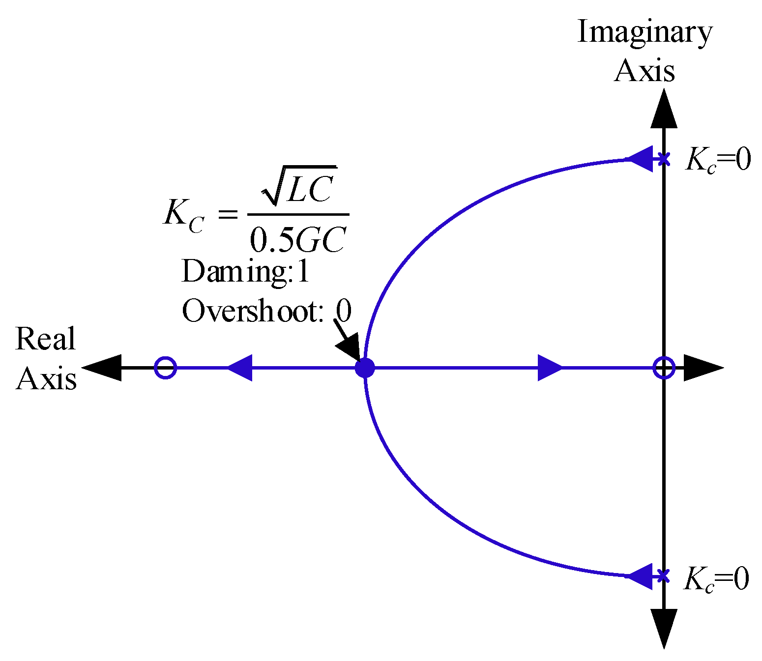
where Kc and G are the current controller coefficient and the inverter gain, respectively. To address the resonance issue, Kc, which represents the gain of the current controller, should be increased. Figure 4 shows the root locus of the inner loop for examining how the roots of the system change with variation of Kc. It is evident that if Kc is chosen bigger than , the inner control will not face resonance and works as an overdamped or a critically damped second-order system [33].
The multi-loop control design requires an approximation of closed-loop TF of the inner loop. The approximation in (3) is not wrong since the inner current loop with designed current behaves like a first-order system as demonstrated in Figure 5 [34].
.
2.3. External Voltage Loop
After designing the current controller, the voltage controller Gv(s) must be designed such that all kinds of loads are fed with a fixed sinusoidal voltage. When the load is nonlinear, e.g., rectifier load, the output voltage contains harmonics. Hence, the limitation of voltage distortion in supplying the nonlinear load becomes a challenging issue, which has motivated the development of a variety of different control methods [33].
The multi-loop control consisting of the inner current and outer voltage loops is demonstrated in Figure 6, in which the PR controller plus a lead-lag compensator are used as a voltage controller Gv(s). Due to the implementation limits, a non-ideal form of PR controller has been used [35], wherein ωcut is the cut-off frequency in the PR controller. The reference signal for inductor current control is the result of voltage control. Voltage control is essential due to the presence of undesired odd-order harmonic contents. Therefore, the main odd harmonics (i.e., 3rd, 5th, and 7th) are suppressed by the multi-resonant controller. Compared to many other methods such as sliding-mode control [36], deadbeat [37], feedback linearization method [38], the effectiveness of this controller is not limited by switching frequency.
The proposed voltage controller is described as follows.
In the above equation, if the voltage controller is assumed as three parts, the first part represents the proportional controller coefficient (Kp) and the second part is responsible for suppressing the resonance of the intended order (i = 1, 3, 5 and 7). So, i represents the harmonic order in Ki (resonance gain), ωcut,i and i × ω0. The lead-leg compensator is used to improve system stability by modifying the system phase response.
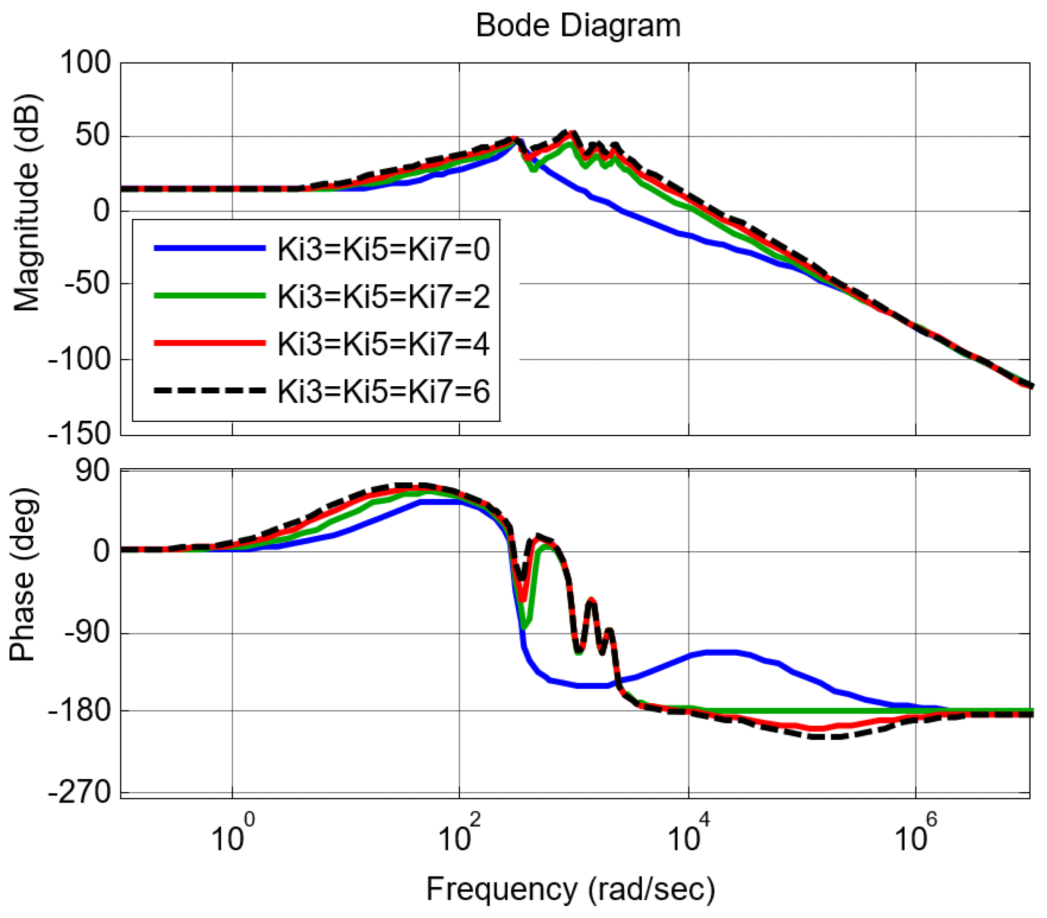
In the following, the design criterium of the voltage controller is investigated by Bode diagram. Figure 7 shows the Bode diagram of the open-loop TF of the voltage loop with different values of resonant gain. If Ki (i = 3, 5 and 7) is increased, then the magnitude of the Bode diagram will be a value more than 40 dB at the tuned frequencies and the control design requirements for steady-state errors less than 1% are fulfilled [39].
3. Enhanced Circular Chain Controller
The 3C method is presented in Figure 8 where Vref is the sinusoidal reference voltage which is used for synchronizing inverters with each other. For parallel operation and equal current sharing, the measured inductor currents are conveyed among the inverters as the communicating signal. In order to share the load current, the reference current of each inverter is obtained by the inductor current of the previous inverter. The reference current of the first inverter is equal to the last inverter inductor current. This can be formulated as follows [40]:
The conventional 3C method is only applicable to parallel inverters with equal power ratings. In this section, this method is modified in a way that suits a system with unequal power rating inverters. The block diagram of the enhanced 3C is shown in Figure 9 wherein (1) the load current can be easily shared between inverters by adding some gains to 3C loop, (2) Connecting and disconnecting inverters do not distort the load voltage, and ratios of current sharing between inverters are kept correct (Hot-swap capability). Signal Enk is determined by the user to activate and deactivate inverter k.
To divide the load current unequally between the inverters, gain blocks are used on the routes of conveyed reference currents. This method is formalized as follow:
In (6), Sk is the nominal power of kth inverter.
4. Simulation Results
To confirm the proposed control method, a UPS system including three inverters with different power ratings and parameters is simulated (see Figure 10). It assumes that the nominal powers of the second and the third inverters are two and three times higher than the first inverter. Inverter parameters are summarized in Table 1 wherein the inductor and capacitor of LC filters are selected based on DC link voltage, switching frequency, and acceptable current ripple for the inverters [41].
Simulation results of supplying linear loads and nonlinear loads by three inverters are shown in Figure 11 and Figure 12, respectively. In these simulations, Inverter 2 is off from t = 0.1 s until t = 0.14 s. Results show that the load current is divided between three inverters before t = 0.1 s, then it is supplied by two inverters between t = 0.1 s and t = 0.14 s, and finally, three inverters provide the load current.
It is evident that the load current is shared between inverters based on their power rating; moreover, turning on and off an inverter does not affect the quality of load voltage (hot-swap capability). The harmonic spectrum of load voltage for supplying nonlinear is shown in Figure 13. The steady-state error for voltage tracking is around 0.66% and total harmonic distortion (THD) of voltage is around 0.36% which meets UPS standards [42].
5. Experimental Results
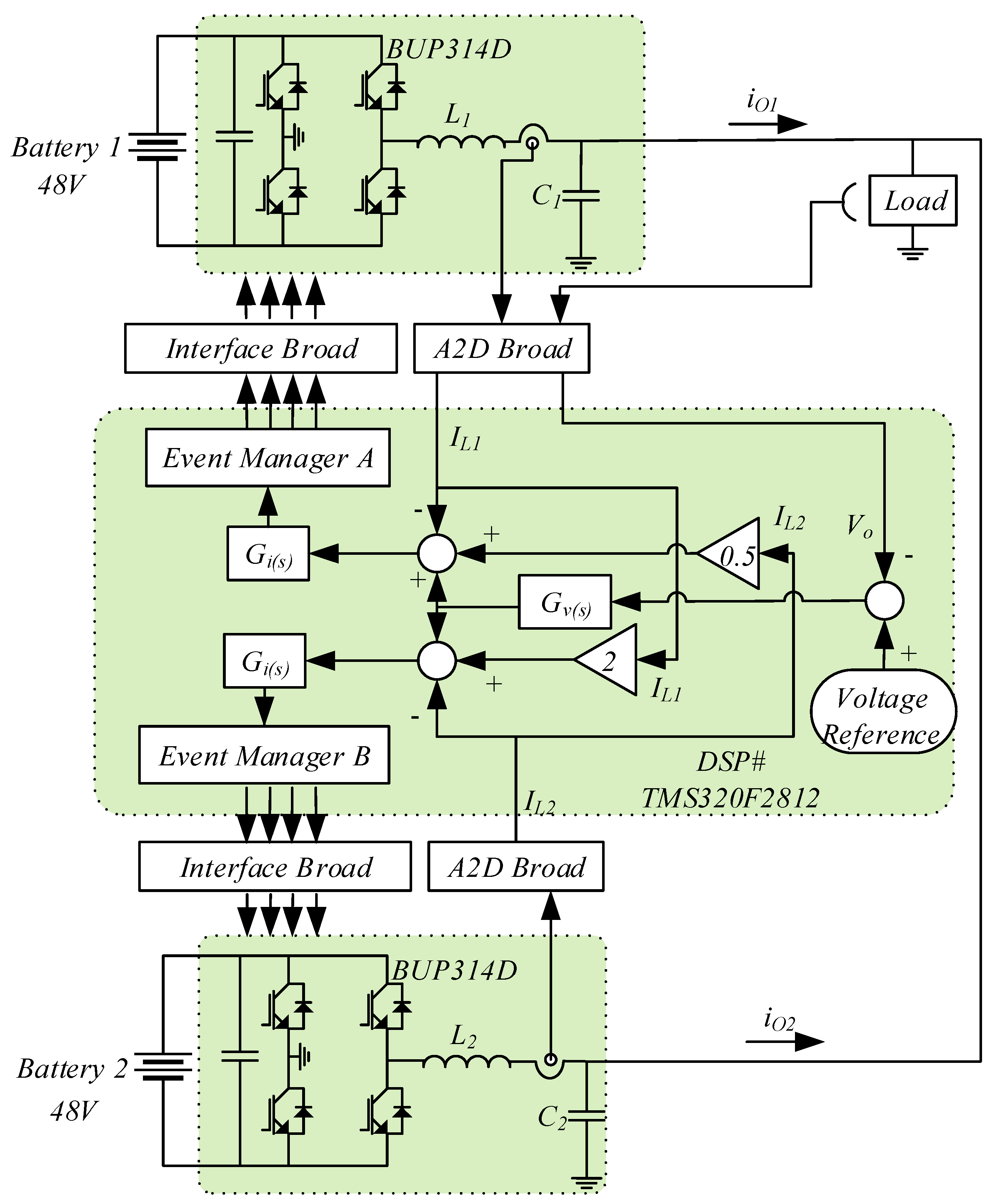
To better demonstrate the effectiveness of the proposed control system, an experimental implementation is accomplished with parameters summarized in Table 2. Figure 14 shows the experimental set. TMS320F2812 DSP is used for controlling the inverters, which are of a bridge type made of four BUP314D switches. An LC filter is employed to provide sinusoidal output waveforms. Inductance current and capacitor voltage are measured through sensors connected to the DSP. The actual ratings of the inverters are the same (100 VA); however, in order to demonstrate the performance of the controller, it is assumed that the rating of Inverter 2 is two times of that of Inverter 1.
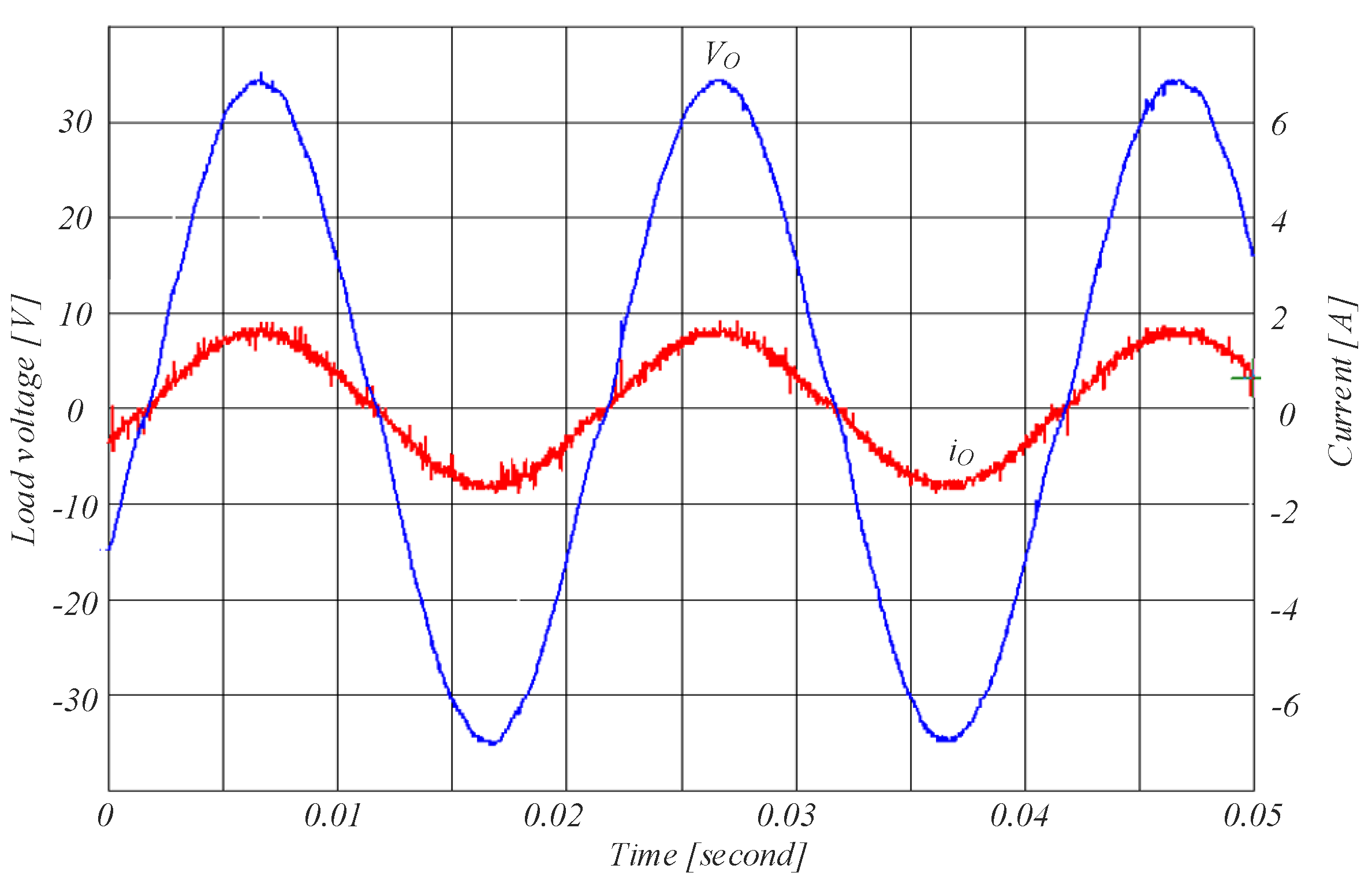
Figure 15 shows the load voltage and current waveforms. Inverter 1 and Inverter 2 currents, supplying linear and nonlinear loads, are shown in Figure 16 and Figure 17, respectively. It can be concluded from the results that the proposed structure properly provides a proper sharing of the load current between inverters.
6. Discussion
- The behaviour of the parallel inverters with unequal power ratings can be quickly deduced from the results presented above: this system allows correct sharing of load current among inverters while maintaining load voltage at its nominal value.
- The results presented above show that the linear and nonlinear load currents are shared with the desired ratio between inverters. It is also important to consider that the inductor and capacitor of LC filter is designed based on the inverter rating; therefore, parameters of LC filters of unequally rated inverters are different as listed in Table 1. The accuracy of conventional current sharing methods depends on the LC filter parameters while the accuracy of the proposed scheme is acceptable regardless of the system parameters uncertainties in transient and steady-state conditions.
- An important aspect to be considered is the hot-swap capability of the system. Consider the case presented between t = 0.1 s and t = 0.14 s in Figure 11 and Figure 12. In this case, the number of inverters reduce from three to two and then, Inverter 2 is reconnected. The behaviour of the system is excellent; the load voltage and current sharing are not affected by turn-on and turn-off of inverters.
- A low harmonic distortion can be achieved at the output of parallel inverter because of the proposed control scheme: the inverter with the proposed PR controller at odd harmonic orders, as voltage controller, can generate a near sinusoidal voltage waveform that will exhibit a low harmonic distortion for linear and nonlinear loads. The harmonic spectrum of the load voltage is shown in Figure 13 for the nonlinear load (the worst case). The THD of the load voltage is less than 0.4% and all harmonic components are smaller than 0.25%.
7. Conclusions
The circular chain control method was used for controlling parallel inverters of unequal ratings. Due to its circular structure, the 3C method is convenient to be used in uninterruptible power supplies in industrial power systems and microgrids. Nevertheless, the conventional 3C control strategy is only applicable to inverters of equal power ratings. This method is modified here in a way that makes it suitable for applications of inverters with unequal power ratings. For proper current sharing regardless of the number of involved inverters and their working modes (off and on modes), measured currents are conveyed in a circular structure through communication links with appropriate gains, which are proportional to inverters’ power ratings. Since there is no need to change the parameters of preinstalled controller, the proposed system provides hot-swap capability, high modularity, and simple the power expansion. The internal controller of each inverter consists of an inner current loop and an outer voltage loop that are designed for proper current sharing and voltage regulation. A simulation study has been accomplished for a system of three unequally rated inverters in different operation conditions and loads. Experimental implementation was also carried out for a set of two inverters with different power ratings. The obtained results verified the proper performance of the proposed control scheme wherein linear and nonlinear load currents were shared with desired ratio among inverters and the load was supplied with a high-quality voltage.
Author Contributions
M.S. (Mahdi Shahparasti) is the main researcher who initiated and organized research reported in the paper. He contributed to the sections on system modelling and controlling, control algorithm development and validation. In addition, as the first author, he is responsible for writing the main parts of the paper, including paper layout and results. M.S. (Mehdi Savaghebi) contributed to analysis, writing and editing of the manuscript. M.H. and N.R. contributed to system modelling and preparing the article draft. All authors have read and agreed to the published version of the manuscript.
Funding
This research received no external funding.
Conflicts of Interest
The authors declare no conflict of interest.
References
- Lahyani, A.; Venet, P.; Guermazi, A.; Troudi, A.; Lahyani, A.; Venet, P.; Guermazi, A.; Troudi, A.; Supercapacitors, B. Battery/supercapacitors combination in Uninterruptible Power Supply (UPS). IEEE Trans. Power Electron. 2019, 28, 1509–1522. [Google Scholar] [CrossRef]
- Kim, S.; Kwon, M.; Choi, S. Operation and control strategy of a new hybrid ESS-UPS system. IEEE Trans. Power Electron. 2018, 33, 4746–4755. [Google Scholar] [CrossRef]
- Wei, B.; Marzabal, A.; Ruiz, R.; Guerrero Ge, J.M.; Vasquez, J. DAVIC: A new distributed adaptive virtual impedance control for parallel-connected voltage source inverters in modular UPS system. IEEE Trans. Power Electron. 2018, 34, 5953–5968. [Google Scholar] [CrossRef] [Green Version]
- Pouresmaeil, E.; Montesinos-Miracle, D.; Gomis-Bellmunt, O.; Sudrià-Andreu, A. Instantaneous active and reactive current control technique of shunt active power filter based on the three-level NPC inverter. Eur. Trans. Electr. Power 2011, 21, 2007–2022. [Google Scholar] [CrossRef]
- Zhang, X.; Fu, Z.; Xiao, Y.; Wang, G.; Xu, D. Control of parallel three-phase PWM converters under generalized unbalanced operating conditions. IEEE Trans. Power Electron. 2017, 32, 3206–3215. [Google Scholar] [CrossRef]
- Khayat, Y.; Guerrero, J.M.; Bevrani, H.; Shafiee, Q.; Heydari, R.; Naderi, M.; Dragicevic, T.; Simpson-Porco, J.W.; Dorfler, F.; Fathi, M.; et al. On the Secondary control architectures of AC microgrids: An overview. IEEE Trans. Power Electron. 2020, 35, 6482–6500. [Google Scholar] [CrossRef]
- Heydari, R.; Khayat, Y.; Amiri, A.; Dragicevic, T.; Shafiee, Q.; Popovski, P.; Blaabjerg, F. Robust high-rate secondary control of microgrids with mitigation of communication impairments. IEEE Trans. Power Electron. 2020, 35, 12486–12496. [Google Scholar] [CrossRef]
- Guerrero, J.M.; Chandorkar, M.; Lee, T.L.; Loh, P.C. Advanced control architectures for intelligent microgridspart i: Decentralized and hierarchical control. IEEE Trans. Ind. Electron. 2013, 60, 1254–1262. [Google Scholar] [CrossRef] [Green Version]
- Han, H.; Hou, X.; Yang, J.; Wu, J.; Su, M.; Guerrero, J.M. Review of power sharing control strategies for islanding operation of AC microgrids. IEEE Trans. Smart Grid 2016, 7, 200–215. [Google Scholar] [CrossRef] [Green Version]
- Guerrero, J.M.; Matas, J.; De Vicuña, L.G.; Castilla, M.; Miret, J. Wireless-control strategy for parallel operation of distributed-generation inverters. IEEE Trans. Ind. Electron. 2006, 53, 1461–1470. [Google Scholar] [CrossRef]
- Aryani, D.; Song, H. Coordination control strategy for AC/DC hybrid microgrids in stand-alone mode. Energies 2016, 9, 469. [Google Scholar] [CrossRef]
- Heydari, R.; Dragicevic, T.; Blaabjerg, F. High-bandwidth secondary voltage and frequency control of VSC-Based AC microgrid. IEEE Trans. Power Electron. 2019, 34, 11320–11331. [Google Scholar] [CrossRef] [Green Version]
- Marwali, M.N.; Keyhani, A. Control of distributed generation systems—Part I: Voltages and currents control. IEEE Trans. Power Electron. 2004, 19, 1541–1550. [Google Scholar] [CrossRef]
- Han, Y.; Li, H.; Shen, P.; Coelho, E.A.A.; Guerrero, J.M. Review of active and reactive power sharing strategies in hierarchical controlled microgrids. IEEE Trans. Power Electron. 2017, 32, 2427–2451. [Google Scholar] [CrossRef] [Green Version]
- Ding, X.; Yao, R.; Zhai, X.; Li, C.; Dong, H. An adaptive compensation droop control strategy for reactive power sharing in islanded microgrid. Electr. Eng. 2020, 102, 267–278. [Google Scholar] [CrossRef]
- He, J.; Li, Y.W. An enhanced microgrid load demand sharing strategy. IEEE Trans. Power Electron. 2012, 27, 3984–3995. [Google Scholar] [CrossRef]
- Nasirian, V.; Shafiee, Q.; Guerrero, J.M.; Lewis, F.L.; Davoudi, A. Droop-free distributed control for AC microgrids. IEEE Trans. Power Electron. 2016, 31, 1600–1617. [Google Scholar] [CrossRef] [Green Version]
- Lu, J.; Savaghebi, M.; Guan, Y.; Golestan, S.; Vasquez, J.C.; Guerrero, J.M.; Marzabal, A. DC-Link protection and control in modular uninterruptible power supply. IEEE Trans. Ind. Electron. 2018, 65, 3942–3953. [Google Scholar] [CrossRef] [Green Version]
- Dheer, D.K.; Gupta, Y.; Doolla, S. A self-adjusting droop control strategy to improve reactive power sharing in islanded microgrid. IEEE Trans. Sustain. Energy 2019, 11, 1624–1635. [Google Scholar] [CrossRef]
- Shamseh, M.B.; Yoshino, T.; Kawamura, A. Current-dependent capacitor voltage control of parallel autonomous UPS systems. IEEE Trans. Ind. Electron. 2018, 65, 2873–2882. [Google Scholar] [CrossRef]
- Tolani, S.; Sensarma, P. An instantaneous average current sharing scheme for parallel UPS modules. IEEE Trans. Ind. Electron. 2017, 64, 9210–9220. [Google Scholar] [CrossRef]
- Guerrero, J.M.; Hang, L.; Uceda, J. Control of distributed uninterruptible power supply systems. IEEE Trans. Ind. Electron. 2008, 55, 2845–2859. [Google Scholar] [CrossRef] [Green Version]
- Lee, W.C.; Lee, T.K.; Lee, S.H.; Kim, K.H.; Hyun, D.S.; Suh, I.Y. A master and slave control strategy for parallel operation of three-phase UPS systems with different ratings. In Proceedings of the Nineteenth Annual IEEE Applied Power Electronics Conference and Exposition, APEC ’04, Anaheim, CA, USA, 22–26 February 2004; Volume 1, pp. 456–462. [Google Scholar] [CrossRef]
- Sun, X.; Lee, Y.S.; Xu, D. Modeling, analysis, and implementation of parallel multi-inverter systems with instantaneous average-current-sharing scheme. IEEE Trans. Power Electron. 2003, 18, 844–856. [Google Scholar] [CrossRef]
- Shamseh, M.B.; Yoshino, T.; Kawamura, A. Load current distribution between parallel inverters based on capacitor voltage control for UPS applications. IEEJ J. Ind. Appl. 2017, 6, 258–267. [Google Scholar] [CrossRef]
- Roslan, A.M.; Ahmed, K.H.; Finney, S.J.; Williams, B.W. Improved instantaneous average current-sharing control scheme for parallel-connected inverter considering line impedance impact in microgrid networks. IEEE Trans. Power Electron. 2011, 26, 702–716. [Google Scholar] [CrossRef]
- Pei, Y.; Jiang, G.; Yang, X.; Wang, Z. Auto-Master-Slave control technique of parallel inverters in distributed AC power systems and UPS. In Proceedings of the 2004 IEEE 35th Annual Power Electronics Specialists Conference (IEEE Cat. No.04CH37551), Aachen, Germany, 20–25 June 2004; Volume 3, pp. 2050–2053. [Google Scholar] [CrossRef]
- Mortezaei, A.; Simões, M.G.; Marafão, F.P. Cooperative operation based master-slave in islanded microgrid with CPT current decomposition. In Proceedings of the 2015 IEEE Power & Energy Society General Meeting, Denver, CO, USA, 26–30 July 2015; pp. 1–5. [Google Scholar] [CrossRef]
- Martí, P.; Torres-Martínez, J.; Rosero, C.X.; Velasco, M.; Miret, J.; Castilla, M. Analysis of the effect of clock drifts on frequency regulation and power sharing in inverter-based islanded microgrids. IEEE Trans. Power Electron. 2018, 33, 10363–10379. [Google Scholar] [CrossRef] [Green Version]
- Shahparasti, M.; Yazdian, A.; Mohamadian, M.; Larijani, A.S.S.; Fatemi, A. Parallel uninterruptible power supplies based on Z-source inverters. IET Power Electron. 2012, 5, 1359. [Google Scholar] [CrossRef]
- Piboonwattanakit, K.; Khan-Ngern, W. Design of the two parallel inverter modules by circular chain control technique. In Proceedings of the 2007 7th International Conference on Power Electronics and Drive Systems, Bangkok, Thailand, 27–30 November 2007; pp. 1518–1522. [Google Scholar] [CrossRef]
- Li, Y.W. Control and resonance damping of voltage-source and current-source converters with LC filters. IEEE Trans. Ind. Electron. 2009, 56, 1511–1521. [Google Scholar] [CrossRef]
- Shahparasti, M.; Mohamadian, M.; Yazdian, A.; Ahmad, A.A.; Amini, M. Derivation of a stationary-frame single-loop controller for three-phase standalone inverter supplying nonlinear loads. IEEE Trans. Power Electron. 2014, 29, 5063–5071. [Google Scholar] [CrossRef]
- Li, Y.W.; Blaabjerg, F.; Vilathgamuwa, D.M.; Loh, P.C. Design and comparison of high performance stationary-frame controllers for DVR implementation. IEEE Trans. Power Electron. 2007, 22, 602–612. [Google Scholar] [CrossRef]
- Shahparasti, M.; Rocabert, J.; Muñoz, R.S.; Luna, A.; Rodríguez, P.; Munoz, R.S.; Luna, A.; Rodriguez, P. Smart AC storage based on microbial electrosynthesis stack. In Proceedings of the 2018 7th International Conference on Renewable Energy Research and Applications (ICRERA), Paris, France, 14–17 October 2018; Volume 5, pp. 1086–1091. [Google Scholar] [CrossRef] [Green Version]
- Tai, T.; Chen, J.; Member, A. UPS inverter design using discrete-time sliding-mode control scheme. IEEE Trans. Ind. Electron. 2002, 49, 67–75. [Google Scholar]
- Mattavelli, P. An Improved Deadbeat Control for UPS Using Disturbance Observers. IEEE Trans. Ind. Electron. 2005, 52, 206–212. [Google Scholar] [CrossRef]
- Bidram, A.; Davoudi, A.; Lewis, F.L.; Guerrero, J.M. Distributed cooperative secondary control of microgrids using feedback linearization. IEEE Trans. Power Syst. 2013, 28, 3462–3470. [Google Scholar] [CrossRef] [Green Version]
- Hosseinpour, M.; Mohamadian, M.; Varjani, A.Y. Design and analysis of the droop-controlled parallel four-leg inverters to share unbalanced and nonlinear loads. Przegląd Elektrotechniczny 2014, 90, 105–110. [Google Scholar] [CrossRef]
- Wu, T.-F.; Chen, Y.K. 3C strategy for inverters in parallel operation achieving an equal current distribution. IEEE Trans. Ind. Electron. 2000, 47, 273–281. [Google Scholar] [CrossRef]
- Shahparasti, M. Distributed generation inverter: New control strategies to supply local load with standard voltage under distorted grid voltage. J. Energy Manag. Technol. 2019, 3, 1–10. [Google Scholar] [CrossRef]
- Botterón, F.; Pinheiro, H. A three-phase UPS that complies with the standard IEC 62040-3. IEEE Trans. Ind. Electron. 2007, 54, 2120–2136. [Google Scholar] [CrossRef]
Figure 1.
The two-loop control structure of a single-phase inverter with LC filter.

Figure 2.
Block diagram of the two-loop control scheme.

Figure 3.
Inner current loop block diagram.

Figure 4.
Root locus plot of the current loop.

Figure 5.
Bode plot of .

Figure 6.
The voltage loop block diagram including a proportional-resonant controller and a lead-lag compensator.
Figure 6.
The voltage loop block diagram including a proportional-resonant controller and a lead-lag compensator.

Figure 7.
The open-loop Bode diagram of the voltage loop.

Figure 8.
Conventional circular chain control (3C) method.

Figure 9.
Enhanced 3C method.

Figure 10.
A simulation case study consisting of inverters with unequal ratings.

Figure 11.
Voltage and current with linear load: (a) load voltage, (b) load and inverters currents.

Figure 12.
Voltage and current with nonlinear load: (a) load voltage, (b) load and inverters currents.
Figure 12.
Voltage and current with nonlinear load: (a) load voltage, (b) load and inverters currents.

Figure 13.
Load voltage harmonic spectrum.

Figure 14.
Experimental setup.

Figure 15.
Load current and voltage waveforms.

Figure 16.
Inverter 1 and 2 currents with a linear load, iO1 and iO2.

Figure 17.
Inverter 1 and 2 currents with a nonlinear load.


Table 1.
Specifications of simulations.
| Parameter | Symbol | Value |
|---|---|---|
| Load voltage | VO | 110 V, 50 HZ |
| Inverter power rating | S1, S2, S3 | 500 VA, 1000 VA, 1500 VA |
| DC source voltage | Vdc1, Vdc2, Vdc3 | 300 V |
| Inductor of LC filter | L1, L2, L3 | 1.35 mH, 0.9 mH, 0.45 mH |
| Capacitor of LC filter | C1, C2, C3 | 40 uF, 60 uF, 120 uF |
| Switching frequency | fs | 20 kHz |
| Linear load resistance | RLl | 6.05 Ω |
| Nonlinear load (diode bridge) | RLn, CLn | RLn = 12.1 Ω, CLn = 2000 uF |
Table 2.
Specifications of experimental setup.
| Parameter | Symbol | Value |
|---|---|---|
| Load voltage | VO | 33 V, 50 HZ |
| Inverter power rating | S1, S2 | 50 VA, 100 VA |
| DC source voltage | Vdc1, Vdc2 | 48 V |
| Inductor of LC filter | L1, L2 | 4.2 mH |
| Capacitor of LC filter | C1, C2 | 10 uF |
| Switching frequency | fs | 6 kHz |
| Linear load resistance | RLl | 22 Ω |
| Nonlinear load (diode bridge) | RLn, CLn | RLn = 22 Ω, CLn = 500 uF |
© 2020 by the authors. Licensee MDPI, Basel, Switzerland. This article is an open access article distributed under the terms and conditions of the Creative Commons Attribution (CC BY) license (http://creativecommons.org/licenses/by/4.0/).
Share and Cite
MDPI and ACS Style
Shahparasti, M.; Savaghebi, M.; Hosseinpour, M.; Rasekh, N. Enhanced Circular Chain Control for Parallel Operation of Inverters in UPS Systems. Sustainability 2020, 12, 8062. https://doi.org/10.3390/su12198062
AMA Style
Shahparasti M, Savaghebi M, Hosseinpour M, Rasekh N. Enhanced Circular Chain Control for Parallel Operation of Inverters in UPS Systems. Sustainability. 2020; 12(19):8062. https://doi.org/10.3390/su12198062
Chicago/Turabian StyleShahparasti, Mahdi, Mehdi Savaghebi, Majid Hosseinpour, and Navid Rasekh. 2020. "Enhanced Circular Chain Control for Parallel Operation of Inverters in UPS Systems" Sustainability 12, no. 19: 8062. https://doi.org/10.3390/su12198062
Note that from the first issue of 2016, this journal uses article numbers instead of page numbers. See further details here.