A BIM-Based Framework and Databank for Reusing Load-Bearing Structural Elements
by
 , ,
, ,
Ingrid Bertin
1,2,* ,
,
Romain Mesnil
1,
Jean-Marc Jaeger
2,
Adélaïde Feraille
1 and
Robert Le Roy
1,3 1
Navier Laboratory, Ecole des Ponts ParisTech, University Gustave Eiffel, CNRS, 77455 Marne-la-Vallée, France
2
Setec tpi, 75012 Paris, France
3
ENSA Paris-Malaquais, PSL University, GSA Laboratory, 75006 Paris, France
*
Author to whom correspondence should be addressed.
Sustainability 2020, 12(8), 3147; https://doi.org/10.3390/su12083147
Submission received: 25 February 2020
/
Revised: 31 March 2020
/
Accepted: 2 April 2020
/
Published: 14 April 2020
(This article belongs to the Special Issue Integration of LCA and BIM for Sustainable Construction)
Abstract
:In a context of intense environmental pressure where the construction sector has the greatest impact on several indicators, the reuse of load-bearing elements is the most promising by avoiding the production of waste, preserving natural resources and reducing greenhouse gas emissions by decreasing embodied energy. This study proposes a methodology based on a chain of tools to enable structural engineers to anticipate future reuse. This methodology describes the design of reversible assemblies, the addition of complementary information in the building information modeling (BIM), reinforced traceability, and the development of a material bank. At the same time, controlling the environmental impacts of reuse is planned by carrying out a life cycle assessment (LCA) at all stages of the project. Two scenarios for reuse design are applied with the toolchain proposed. A. “design from a stock” scenario, which leads to 100% of elements being reused, using only elements from stock. B. “design with a stock” scenario, which seeks to integrate as many reused elements available in the stock as possible. The case study of a high-rise building deconstructed to rebuild a medium-rise building demonstrated that the developed toolchain allowed the inclusion of all reuse elements in a new structural calculation model.
1. Introduction
The environmental findings require rethinking our construction methods to fight against the depletion of natural resources and greenhouse gases (GHGs) emissions that conduct to climate change. The Intergovernmental Panel on Climate Change (IPCC) reminds us that we face significant risks with global warming of 1.5 °C and more [1], which seems to be looming if growth keeps its current pace. In this context, the building sector is a major contributor to three environmental hazards: resource depletion, energy consumption and waste generation [2,3,4,5]. The building sector is the main emitting sector able to improve the global environmental impacts significantly, according to the United Nations Environment Program (UNEP SBCI) [6].
The Organization for Economic Co-operation and Development (OECD) report [7] shows that construction materials dominate total materials use in 2011 and 2060, and their use will be at the least twice higher between 2011 and 2060. It depletes two-fifths of global raw stone, gravel and sand and one-fourth of virgin wood [8]. Therefore, the construction sector is the most consumer of materials and the largest exploiters of natural resources [8], accounting for between 40% of the total raw materials consumption [9] and 50% [10].
This growing development has repercussions on the emission of GHGs, among other indicators. In France, the construction and building industry is the leading emitter of GHGs [11], i.e., 33% of total GHGs. Several studies confirm this number worldwide [6,12,13]. Kumar Dixit et al. [8] define the embodied energy (EE) and embodied carbon (EC). EE during the construction phase is the amount of energy used for the extraction of raw materials, the production and transport of building components as well as the building construction and end-of-life (EOL). Moreover, EC refers to the associated GHG emissions [3]; the operating energy during the operation phase as energy consumption and associated operational carbon emissions during the use phase of buildings (heating, cooling, etc.). The average value of EE is 50% of the total primary energy demand [14]. The share of operational energy seems to decrease recently (even disappearing in passive or zero energy buildings) with technical progress and, therefore, the share of EE increases [15].
Another impact of the construction sector is due to waste generation [5,16]. Most of the literature focuses on waste management, which shows a great interest in reducing the construction and demolition waste (CDW) generated by the construction sector as it represents around 40% of the waste produced [17]. Cai et al. [18] and Lismont et al. [19] explained that in Europe, about 25–30% of the waste result from the building sector amounting to 870 million tons annually and Brütting et al. [3] estimated this share at more than a third of the waste. Meanwhile, we face stricter disposal and landfill regulations, and fewer landfills are available [20]. According to the Environmental Protection Agency (EPA), currently, only 40% of CDW materials are recycled, reused or recovered by energy facilities, while the remaining 60% are sent to CDW landfills [21]. Thus, building structures generate a large amount of CDW [2]. Besides, in a post-disaster context (earthquakes and other natural disasters, war) the implementation of a reuse process not only makes it possible to limit the generation of waste but also to respond to a health and human emergency [22,23].
Furthermore, load-bearing systems have a major impact among building components because of their material and energy-intensive manufacturing process [3]. Load-bearing systems represent the most substantial part of EE [24,25], with 39% according to Marzouk et al. [26], and 50% and above of the total building embodied impact also called embodied carbon for Kaethner et al. [27] and Veselka et al. [28]. As such, foundations and structural elements are mainly part of the building to improve in order to decrease the EC [25,26]. Thus, among the various stakeholders, structural engineers have a decisive role in the environmental impact of buildings [26,29] and must master life cycle assessment (LCA) to reduce this impact judiciously.
Reuse in construction can potentially target around three billion tons of raw materials worldwide, representing significant economic interests, around 40–50% of the total flow of the world’s economy [18]. The reuse of load-bearing components over several building life cycles [30] is a promising avenue for meeting the environmental challenges facing the construction sector [31]. Most of the designs including reuse of load-bearing components of structures, come from design for deconstruct (DfD) [18,32], which is a circular economy strategy [32]. DfD helps to promote reuse by allowing the dismantling of components [18], including GHG reduction, energy and raw materials saving, natural resources preservation, waste reduction, job creation [4,18].
Thanks to all avoided impact [30] it induces, reuse has the potential to significantly reduce the impact of construction, by reducing GHG emissions, considerably limiting the depletion of resources and avoiding the production of waste. As such, reuse constitutes the most promising avenue [5] and allows several life cycles of structural elements that offer an under-explored opportunity to reduce the environmental footprint of the building sector [2].
Several policies, therefore, encourage the establishment of a circular economy. Thus, in Europe, several action plans have been issued and are underway, such as closing the loop—An EU action plan for the circular economy in 2015 or the European Green Deal in December 2019. In France, the Environment Code defines reuse as “any operation whereby substances, materials, or products that are not waste are reused for the same purpose for which they were designed.’’ With a view to this, in April 2018, the French government also drew up its roadmap for developing a 100% circular economy (CE) seeking to ”turn existing buildings into a bank of future construction materials”. In this perspective, the development of tools resulting from the building information modeling (BIM) process can make it possible to set up material banks but also the traceability necessary to access the characteristics for a new use [22].
Despite the climate emergency, the enormous potential of reuse to reduce the impact of construction, and the political incentives, this process is underdeveloped. Notably, at the level of construction in Europe, the reuse of load-bearing elements is not only the most promising but also the most feared because it involves many risks in terms of responsibilities for the designers and builders. So, this research aims to propose a complete methodology to maximize reuse in construction and guarantee safety. The method declined in this paper through the definition of a BIM-related bank of materials feeding LCA can anticipate the reuse of currently designed buildings. Anticipating reuse in today’s new buildings can allow maximum reuse at the EOL. Our study applies to high-rise buildings (HRB), to build up a substantial stock. The cost/benefit analysis also provides support for a large number of elements constituting the stock to be able to set up a reuse strategy.
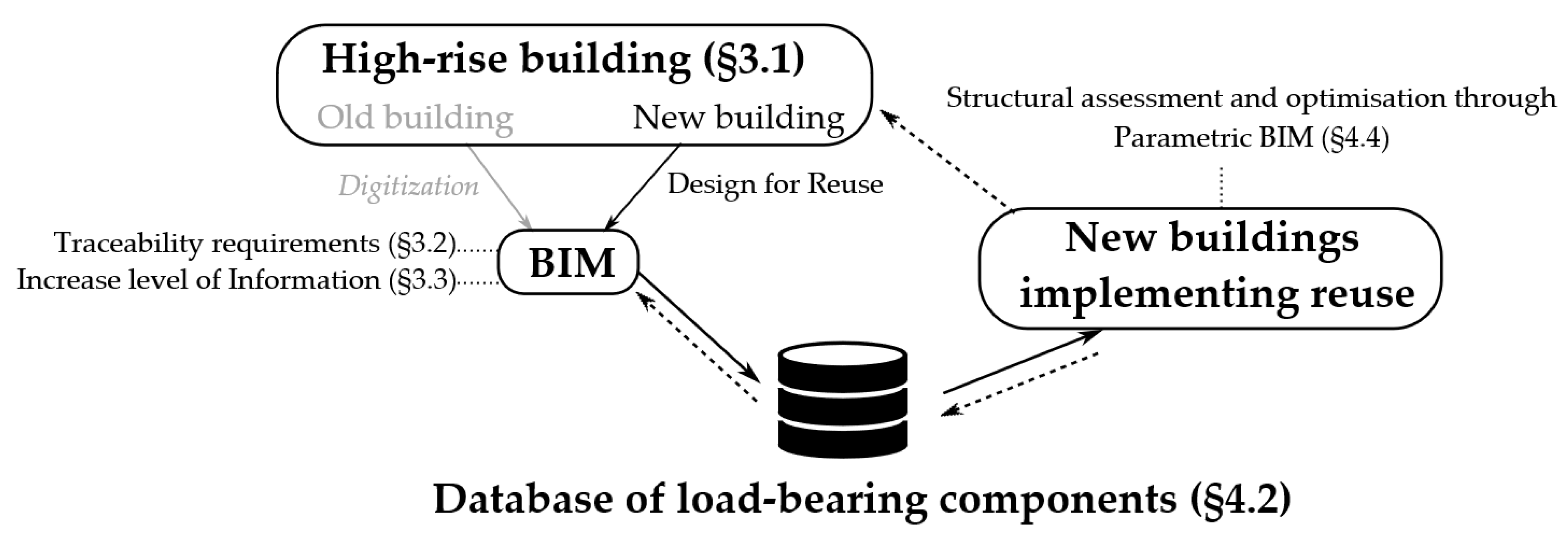
In the following part, we will review the literature on these three main topics Reuse, BIM and LCA. Then, this study will propose a method summarized in Figure 1 and based on:
- the concept design for reuse (DfReu) applied to high-rise buildings (HRB),
- traceability requirements for long-term reuse
- a BIM framework adapted to the reuse of load-bearing elements and their LCA
- the setting up of a materials bank
An application will then test the method and its toolchain with a case study based on HRB. Finally, we will discuss this proof of concept applying the proposed suite of tools.
2. Literature Review
Research on the reuse of load-bearing elements from demolished buildings remains relatively limited; the reuse of concrete elements is even less known [18]. It is all the more true for research regarding anticipated reuse in new structures. Nevertheless, several areas of research have focused on concepts that we need to master to tackle the anticipation of the reuse of structural elements. First of all, we need to clearly define the key concepts and analyze the progress of research in these areas:
- design for reuse (DfReu) (not enough discussed in the literature) to distinguish from design for deconstruction DfD (already present in several articles)
- the question of DfReu’s assessment by the LCA
- the potential of the BIM process for reuse
- BIM and LCA integration
- the materials bank mainly supplied by the BIM models
- traceability to capitalize with the materials bank
2.1. New Design Approach Including Reuse, by Design for Reuse (DfReu)
Design for deconstruct (DfD) is an existing concept [32] mentioned in the introduction. However, DfD is based on deconstruction and reduction of the waste but does not sufficiently integrate the anticipation of reuse. The two concepts design for reuse (DfReu) and design for deconstruction (DfD) are quite distinct. DfReu is specific to design for reuse (not recycling). Whereas DfD is more global to facilitate deconstruction but maybe for simple separation for recycling or energy recovery and not necessarily for reuse. However, DfReu includes facilities for anticipating deconstruction. Therefore, the DfReu concept is privileged for the follow up of our study.
Several difficulties have already been identified with reuse [18,33], such as a lack of guidelines, the need of certifying reclaimed components, safety guarantees (especially with structural elements), correct rejoints, improved DfD method for reuse aspects, financial incentives such as increasing landfill costs. Our study aims to increase these guidelines for designers and builders significantly.
As mentioned in the introduction, the load-bearing elements have the most significant environmental impact and demand a special effort to reuse them. However, one of the challenges of load-bearing elements reuse is allowing a large number of spatial possibilities. This means that with a minimum of different elements it is necessary to be able to respond and adapt to a maximum number of floor plans, spans, loads, support layouts, connection types, according to Fivet [31] and Bertin et al. [33]. We must implement a new paradigm since the conventional structural design process is reversed [2] and the reused elements could impose spans. The availability of the stocked elements with their own mechanical and geometrical properties will determine the future design to adapt. Brütting et al. [4] worked on a given stock optimization by presenting optimization techniques to design truss structures with the most given reused component. The reuse of old load-bearing systems remains complex [18]. Thus, the anticipation of reuse in current projects and future projects, as proposed in our study, is essential and allows an optimal recovery rate.
As a consequence, reuse requires additional actions such as assessing residual performance, evaluating the possibility of reassembly [33], but technical solutions exist such as remediation, repair, reinforcement with fiber reinforced polymer (FRP) confinement and redesign of connection [18]. In some cases, the torsor of forces will change on the reuse elements compared to its previous function, which necessitates that new properties be known for the recalculation [5]. To this purpose, steel and timber linear elements (bars, beams, cables) are more suitable, as they often include reversible connections [2,3]. Our research shows how to reduce these additional actions with proper traceability. Besides, the LCA must make it possible to assess the impact of reuse. Hence, we review the limitations of current LCA practices in the following section.
2.2. LCA, ISO Standards and Limits
ISO14040 [34] defines LCA as “a technique for assessing the environmental aspects and potential impacts associated with a product, by compiling an inventory of relevant inputs and outputs of a product system, evaluating the potential environmental impacts and interpreting the results of the inventory analysis and impact assessment phases” [15,35]. Likewise, ISO 14044 [36] describes the way to interpret the LCA results [25]. Though the reuse of materials seems most promising, ahead of recycling, to reduce the environmental impact of construction, we must take care to accurately assess the impact of construction and deconstruction processes through LCA.
Many limitations in LCA achieved through case studies are listed in the review paper [37], such as ignored transportation and construction impacts, manual Export and Import, assumed industry average for all the impacts. Hoxha et al. [6] discussed on how to address data uncertainties through contribution and sensitivity analysis and draws attention to the implications for LCA. At the same time, Najjar et al. [38] highlighted several gaps, such as incomplete databases or insufficient data at the early design phases that reduce the potential for LCA applications. Most studies present simplified hypotheses due to lack of incoming data, especially for EOL scenarios in which ”only demolition and disposal to landfill sites will be considered” [39].
Although most of the papers have focused on LCA methodology, some provide results allowing to give impact results, especially outside the most widespread climate change. Thus, according to Marzouk et al. [26] study, “manufacturing and transportation off-site phase represents the highest weight of ozone-depleting particles with 92.83% while deconstruction and demolition phase’s largest contribution is in eutrophication particles”.
Some difficulties in evaluating reuse impact with LCA are due to several uncertainties such as full use of lifespan, the number of use cycles, reconditioning operations, resulting in a lack of data [40]. We must develop other tools in parallel with LCA to assess the impact of reuse such as the introduction of new measures as reuse potential indicators [5] based not only on direct impact during manufacturing, construction or deconstruction but also on traceability identification, demountable ability, adaptability to several new use abilities. Reuse remains a complicated issue since LCA needs to develop a methodology for taking into account the different cycles of use for the same product. This is notably due to the different possible scenarios for the cycles of this product, inevitably leading to uncertainties. Also, the inclusion of these scenarios is very time-consuming. Our study seeks to make a more effective environmental impact assessment possible, particularly with the integration of LCA into BIM, as discussed later.
2.3. Use of Building Information Modeling (BIM) for Reuse
As previously noted, compatibility with BIM tools is expected to develop the concept of design for reuse (DfReu). Sustainable topics in BIM practice have considerably multiplied lately [10]. Thus, there is still a lack of designer help with BIM tools mostly focused on visualization and estimation prediction. Current BIM-aided construction waste minimization framework aims to reduce CDW generation by a decision-making framework [41,42,43], but future works, such as our study, need to link BIM to construction waste, also during the design phase. Two major studies dedicated to deconstruction could be adapted to the specific objective of reuse and will be taken into account in our study. Thus, Akinade et al. [44] developed a BIM-based deconstructability Assessment Score (BIM-DAS) to help determine the possibility of deconstructing a building. This score emphasizes criteria to facilitate deconstruction ability but does not guide designers with methodology. The residual performances of building elements are still insufficiently assessed and Akanbi et al. [45] provide additional elements with a BIM-based whole-life performance estimator (BWPE), which takes into account the aging criteria of the materials to allow their reuse.
A study addressed the design for deconstruction (DfD) design criteria [46] based on professionals’ feedbacks and the need to implement Industry Foundation Classes (IFC) models with DfD-BIM software data. The IFC interchange format for the BIM model is approached by several studies [47,48] to integrate data relating to sustainable development but experiences difficulties due to generated file errors during export and import [49]. In this regard, several papers showed the weak interoperability, the lack of industry standards holistically covering the various application areas of BIM for sustainable buildings, the lack of methods and low accuracy of BIM-based prediction models [50]. The methodology proposed in our study will propose an extension of the BIM standards.
The level of detail or level of development (LOD) is a current standard describing the level of accuracy of BIM modeling developed by the BIMFORUM [51]. LOD are broken down into five categories: 100 for low information content and 500 for high information content. The establishment of property criteria for reuse has more to do with the LOI, Level of Information of the BIM model. Forth et al. [49] recommend creating an accurate material nomenclature with affixes to help ensure correct allocation of material specifications to components, containing e.g., the minimum compressive strength class for concrete, species of wood or type of reconstituted material for wood, or type of metal fabrication. Promoting BIM through LOD requires a better understanding of how reuse potential values should be accounted for regarding components such as manufacturing data, mixtures, material grade, material strength, properties, etc., as well as the construction techniques used and the way components are connected with other components [5]. For this purpose, the recent European Union (EU) funded project, BAMB, highlights the concept of building passports, by describing the material composition data of buildings in the form of material passports [52]. Reuse must also be able to rely on BIM to improve the definition of the remaining service life of reused components and understanding of the reuse of structural elements such as their residual capacity. [18]. Our methodology provides a nomenclature compatible with the BIM process and specified explicitly for the reuse of structural elements.
2.4. BIM and LCA Integration
Several papers develop the relation between BIM, LODs and LCA [53,54] and ditto for 6D BIM (covering environmental data relating to sustainable development) [52] with repercussions on the way to structure Life Cycle Inventory (LCI) and to use LCA datasets. By understanding the limitations of these BIM data streams to perform an LCA, we can divide current practices into two main parts. On the one hand, there is geometrical related information extracted from the model (bill of quantities, type of material) which induces a specialized LCA software secondly, and on the other hand, specific LCA data contained directly in the model with a direct LCA plugin in a BIM software [37]. Workflows enabling BIM to export input data for LCA software are linking BIM and LCA. It is recognized that the BIM-LCA connection is not yet optimal [55]. The literature highlights the complexity to manage between precise data requirements and simplified estimations needed in early stages [9,25,56]. Some studies try to address these issues providing methods as a first approach to obtain LCA results with few data [25].
Scarce papers have worked to link 6D BIM and LCA and to refine the environmental data attached to BIM objects to facilitate the extraction of data feeding the LCA software [55]. 6D BIM can help establish the framework to guide the practitioner to fill in correctly the digital model and to save time when performing the LCA. However, most BIM-based LCA methods papers do not precise the LOD for the LCA [25,56]. To achieve reuse, we should provide and integrate necessary BIM-attached information to simulate the assembly and disassembly process, such as a deconstruction plan [57], material properties enabling LCA performing [38]. Indeed, LCA requires rigor and comprehensive data obtained at an advanced stage of the project, whereas engineers need a simplified LCA in the early stages when we can still change the design choices influencing the environmental impact with a low LOD in the BIM model. This difference of accuracy may affect the results obtained with often higher quantities overestimated in early stages (low LOD 200) and a general reduction of impacts obtained with refined quantities in the advanced phase of the project (higher LOD 350 and above), [14,56]. It is preferable to carry out comparative LCA for a given LOD and phase, as the final result is questionable. Three main strategies have been developed in the literature: perform an LCA from a dedicated software (enter data), from a BIM software (integrated LCA plugin, automatic data extraction), from an external facilitator as a web platform (automatic extraction of BIM data and automatic import of LCA data) [58].
Numerous tools and frameworks to improve the BIM-LCA workflow and interoperability have been developed to enable faster and better assessment as [49,59,60,61] but are limited to data exchange and do not take into account the capacity of the designer to change the design and offer no design option to reduce the environmental impact. However, Wastiels, L. [58] takes also into account BIM-LCA to give real-time feedback on design decisions. Automate the integration of BIM data into LCA software and facilitate BIM objects’ attributes extraction makes it easier to update data when the project design changes by avoiding two update operations (BIM software then LCA software) to keep a single update (BIM software) [58] until feature real-time update. The guidelines accompanying the nomenclature we propose will improve BIM-LCA workflows.
2.5. Material Bank, from the Project Database to the Big Data
Once the BIM model has been correctly established and filled in, we must capitalize data it contains on a database. This database makes it possible to build a vast catalog of elements constituting a building that could be made available for future reuse. Mainly unique recent research explored the establishment of a material bank [18] to stock material properties; several papers present the interest of such a development [48] to achieve reuse. In an existing old structure context, a material or component bank could manage more effectively their direct reuse [18]. Brütting et al. [4] also claimed that in the future, effective collaboration between element stocks, databases, and a market for reused elements would facilitate the reuse process. Cai et al. [18] recommends that the bank could help to store and to sell materials and components in a factory or center shop of the bank, and certification of materials and components. Urban mining and building stock can feed a generalized database with the help of drones, photogrammetry, laser scanning and greatly facilitate designers’ access to a wide choice of reusable materials. We propose in this paper a framework for building up this material bank for the reuse of load-bearing elements.
Concurrently, the problem of the impact of the massive datasets produced via these material banks and during the service-life appears. More and more complex BIM models will require higher information storage capacity as we generate huge amounts of data, especially as the monitoring of components is set up [30]. Accordingly, the literature construction sector generates massive data, mainly through BIM models [30], until they require 50 GB in size. As the number of data are continuously increasing, primarily because of the use of sensors and persist beyond the EOL, this phenomenon is expected to worsen, leading to more abundant sources of “BigBIMData” [43]. The use of cloud-based BIM technology also needed, according to KwokWai Wong et al. [30], will contribute to ‘big data’. Santos et al. [10] also approached the intellectual property, which condemns the lack of standards that cover intellectual property rights of data shared throughout a BIM-based project. This also has repercussions in terms of responsibilities, such as regarding insurance, as we will see later.
A material bank could lead to assess numerous simulated data sets, statistical relationships between stocks of components and available (re-)arrangements to fix new design principles for ensured reusability [31]. The material bank can also constitute an opportunity to establish the certification of materials and components providing an insurance or guarantee for critical properties of the reused materials and components, such as residual load-bearing capacity assembly ability and potential degradation ratio under certain environmental use conditions. Regarding Cai et al. [18], it is the most crucial process that could be supported by Government politics by certificating material bank workers and classifying the qualification of the bank. It may provide quality to ensure business exchanges.
Considering these data problems, we endeavor to propose a nomenclature containing the proper measurement of data required for the reuse of load-bearing elements in this study.
2.6. Traceability, Monitoring and Predictive Approach
One of the shortcomings noticed to facilitate reuse is the need for reliable traceability. The BIM model can inform and store information. Furthermore, the digital model is not sufficient to ensure the sustainability and integrity of the data and must be coupled with physical traceability devices. One of them is the Radio Frequency Identification (RFID), allowing tracking and archiving the properties of structural construction components [62]. RFID chips can be incorporated inside the components or attached to them [18]. Quick originality codes or bar codes pasted on the surface of the elements [18] are also traceability solutions. Thus, RFID-BIM technology and potential application is still a niche [62]. Yet, incorporating sensors’ data into the BIM model should contribute to this innovative field [10,28], as it could feature GPS and localization ability [62].
Monitoring has been used mainly for the operation and energy consumption of buildings, but there is also an interest in monitoring and preserving the materials used. KwokWai Wong et al. [30] also incite to generate a ‘one-stop-shop’ BIM for environmental sustainability monitoring and management over a building’s full life cycle. Current predictive approaches are already in place for predictive analytics and waste estimation [43]. KwokWai Wong et al. [30] also promote the development of predicting, managing, and monitoring the environmental impacts of project construction thanks to BIM. Monitoring is also promising about following and assessing all changes during the construction phase and their environmental impact, as far as taken into account LCA update [28]. The guidelines proposed in our work link the relevant traceability systems to reuse load-bearing elements.
Finally, the literature addresses the construction sector impacts with a desire to reduce the CDW in current demolitions, but only a few studies explore anticipating reuse in buildings designed today. Several design methodologies for reuse are based on principles of easy disassembly, but there are still difficulties in characterizing residual performance, responsibilities and insurance, phasing of deconstruction and structural reassembly. The article we presented helps to overcome these difficulties and provides useful guidelines for practitioners. The BIM is particularly enthusiastic support for compiling and sustaining the expected data for reuse and is a pillar of the methodology we propose. All of this data must then be usable for performing an LCA. Current LCA methods do not take into account all the benefits of reuse (such as the multiplication of use cycles) and need to be improved to scientifically assess the different impacts, benefits or disadvantages, of the reuse process on the environment.
3. A method for the Creation and Capitalization of Data
Under this part, we will develop a database integration framework linked to the BIM model and the structural calculation software, necessary for the reuse of load-bearing elements. This framework includes a proposal to define new LOI in the BIM process. An application to a high-rise building (HRB) will mobilize the defined toolchain.
3.1. The Predisposition of High-Rise Buildings (HRB) for Reuse
Reuse calls for maximizing the number of similar, simplified and easily disassembled components. To this end, HRB is particularly suitable for reuse since they have many identical elements and often have the same type of span for the same program. Horizontal load-bearing elements are most of the time the same for the entire building, and vertical load-bearing elements such as columns are often the same within the same HRB block. Among the load-bearing systems, the best performing is the outrigger and diagrid structures [24]. However, this leads to the development of dismountable connections compatible with great heights and to anticipate the deconstruction process [24]. It is preferable to use dry mechanical connections. The concrete elements constituting the core and foundations are particular to a given plot and very rarely reusable. Therefore, it is necessary to minimize the levels in the basement.
The digital mock-up offers a 3D view and the ability to attach information to BIM objects as well as generate technical documents, such as construction drawings and deconstruction plan. Currently, the structural properties are not well detailed. We propose to increase the LOD/LOI in this article. Besides, traceability systems are to be provided, such as barcoding/labeling of materials, RFID tags, sensors, as additional support of the data, and in connection with the digital mock-up. These technologies will be the relay of the digital mock-up in particular for the stages of disassembly, transportation and storage.
3.2. The Need for Data Traceability and Engineer Responsibility
The many current rehabilitation projects require recognition of the existing structure. This current method of recognition can be integrated into the method to anticipate reuse in 30, 50, or more years. Thus, the data of the load-bearing elements must be tracked during the design phase. For the reuse of load-bearing components, the physical and mechanical properties of the materials must be known at least. These data to be collected must be specified according to the type of material: concrete, steel, timber, and according to the structural function: column, beam, load-bearing wall, transverse wall, slab. In some cases, the complexity of the structure to be dismantled or the future class of use of the load-bearing elements requires additional studies by structural engineers.
At the same time, we must take into account that the model is used and completed by different stakeholders of the chain according to their needs. At the end of the process, some data are then definitively lost. Therefore, we should pay particular attention to finding digital building models and as-built documents in case of reuse. To avoid data deletion and to ensure a level of confidentiality, partial access to data according to the actors, must be provided via a system of filters.
The structural engineer who decides to reuse a load-bearing element must ensure that he has the characteristics of this element for essential reasons of responsibility. It is also crucial to check the living and operating conditions of the entire building from which the element comes. We can classify the data of the load-bearing elements of an HRB into four categories:
- the static properties: composition, geometry, relevant standard, etc.;
- mechanical properties (work behavior): position, type of loads, connection conditions, strength class, applied stress, creep, aging characteristics, etc.;
- mechanical properties for the overall behavior of the building structure: exposure class, differential shortening, soil compaction, differential displacements between floors, top displacement, top acceleration, scaling criteria, the service life of the structure, etc.;
- information relating to the reuse process: deconstruction phasing, resource diagnosis, residual performance tests, etc.
All of these measures can contribute to better understanding the life of a structure, thanks also to monitoring to anticipate aging, marking and geolocation of elements, recording of deformation alerts in real-time, historical meteorological, or environmental conditions. These data are already collected as part of structural health monitoring (SHM) and are adaptable for reuse. The SHM allows the updating of information on the aging of elements. The SHM can be directly coupled to the initial calculation model to update the consequences of events experienced by the structure. Finally, active traceability is, therefore, better suited to data collection to monitor the overall behavior of the (mechanical) structure.
To assess the risk of reusing a structural element and extending its useful life for a “new life”, another level of response can be provided via the principle of predictive analysis. The statistical processing of numerical data recorded during the first life must allow reusing a structural element with an understanding of its behavior far superior to that provided by traditional analysis processes. In the case of an existing structure, a predictive analysis, based on the evaluation and statistical processing of data measured in situ, makes it possible to establish correlations between the data, for example between observed displacements and applied actions and makes it possible to predict the structure’s subsequent behavior. We can base the future behavior on knowledge of the actual behavior and the increasingly fine-tuning of the predictive model according to the data measured in response to climatic or other events. The data recorded by the sensors will be analyzed and interpreted to provide a real-time dashboard of the building’s mechanical behavior.
A precise orchestration allows to:
- Store this data according to predefined data architecture and in a secure storage area,
- Define the correlations sought between the data collected and build the processes to establish these correlations (data science),
- Implement a “Machine Learning” type process to learn and control the behavior of the work overtime in an increasingly fine-tuned manner,
- Reach a statistical predictive model capable of predicting the future behavior of the structure in the face of future external stresses.
The predictive model is based on observation and measurements of actual behavior and, therefore, directly integrates uncertain elements into physical-mathematical modeling (aging law and material damping rate, modeling of applied actions, etc.). As such, it will provide more precise information on the future behavior of the structure (with optimized safety coefficients covering the uncertainties) and will also provide a more precise understanding of its useful life. However, not all the information required for the structural analysis is easily measurable, for example, internal stresses and stress rates of material, which we can find in the physical model. Therefore, one method would be to couple the two approaches.
We must adjust this principle to isolated elements of the structure (a column, a beam) to know the local stresses and deformations and to make the elements available for reuse.
3.3. A New Proposal of LOD and LOI Definition within 6D BIM
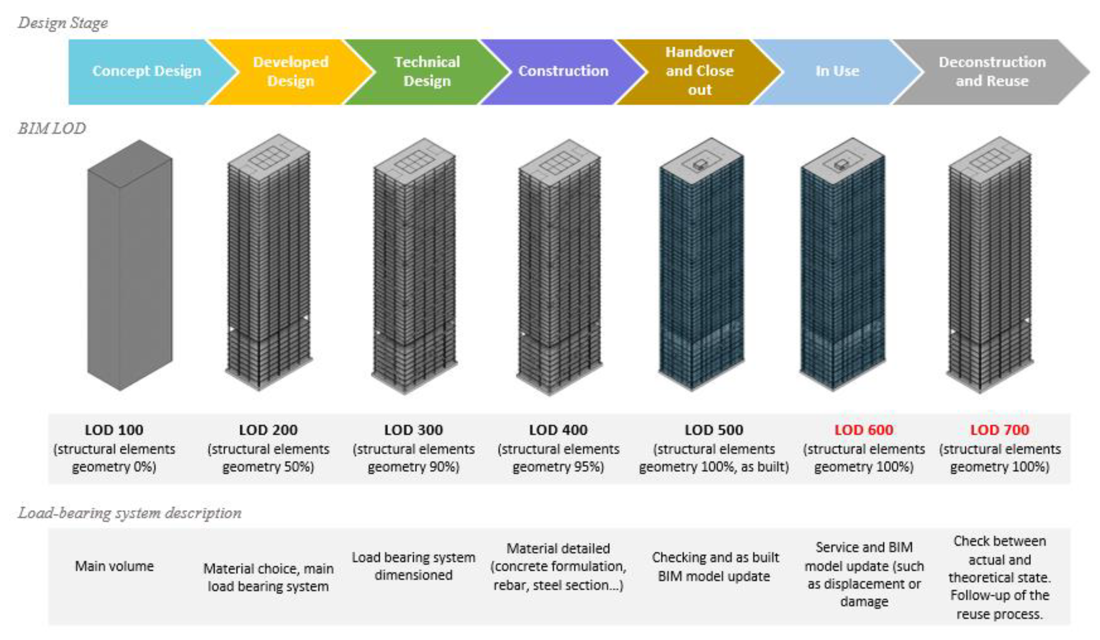
Tools are being developed to optimize deconstruction and EOL but not for design for reuse (DfReu) practices. The described methodology herein aims to design structural elements by increasing the 6D BIM and LCA-related parameters. The commonly recognized reference document by practitioners is the definition of LOD by BIM Forum [51]. According to this reference, the various LODs from 100 to 400 specify the expected geometric representations, for example, for Precast Structural Column (Concrete) at LOD 400 “Element modeling to include: all reinforcement including post-tension elements detailed and modeled, finishes”. At LOD 500, all references consider an “as-built structural model” as confirmed by CIC Building Information Modeling Standards in Hong Kong. The five common phases used in this study are Project Planning/ conceptualization (PP), Project/preliminary design (P), Building Permit Application/development (BPA), Tendering/ detailed design (T), Construction (C) as described by [25]. This article describes the accuracy of a LOD 600 concerning the working life phase, and a LOD 700 concerning deconstruction/reuse phase, for the load-bearing elements in Figure 2. The complete table of detailed structural properties (corresponding LOI) can be found in Table A1.
We propose two new definitions of LOD herein to specify the details that the model must include for long-term reuse. In parallel, LOI (the level of information) points out the attributes expected. We can consider that the LOD/LOI 600 corresponds to the information added during the service, and we will not develop this point in this paper, except to anticipate reuse. A LOD/LOI 700 could consist of the data expected to reuse at the EOL and must, therefore, be anticipated from the design phases, then be checked during execution and then be resumed at the EOL, while having the trace of events occurring during maintenance. To this end, we implement the four categories of information described above, integrating previous research into the literature [5,17].
For the time being, the 6D BIM information is not complete in the proper description of the LODs, LOI. Therefore, this article identifies the need to specify new LOI 600 and 700. Today, the development of expectations in terms of the information contained in the BIM model is such that we talk about LOX as there can be so many levels of detail [64]. The LOIN (Level of Information Need) groups together the information needs, where the expectations regarding the reuse process can be specified according to ISO 29481-1 [65] and ISO 19650 [66].
3.4. Bank of Available Materials and Just-In-Time Circular Flow
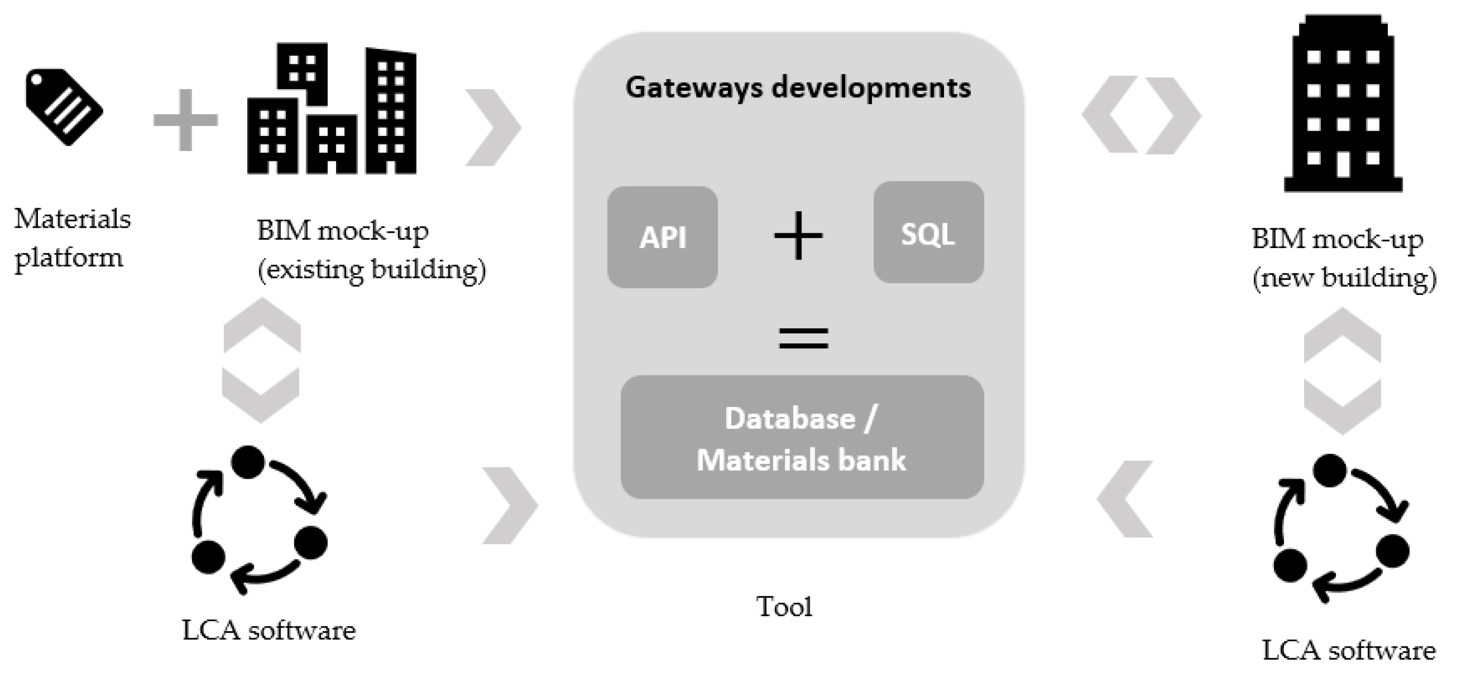
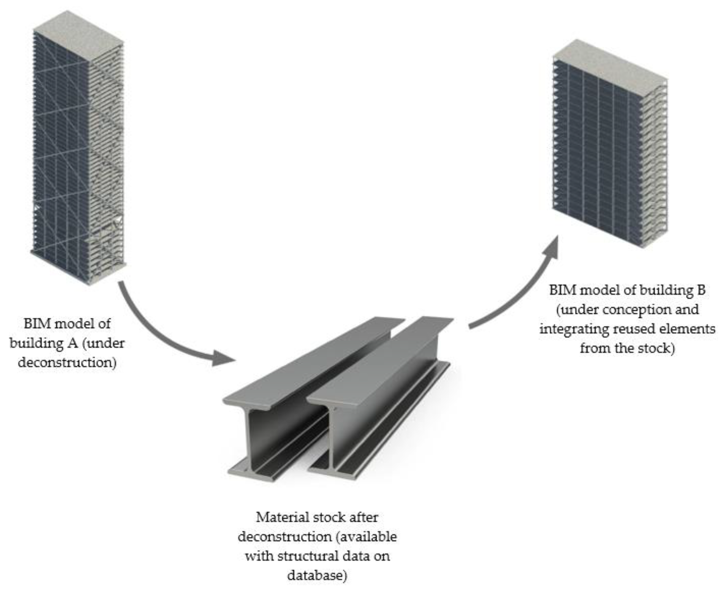
The case study described in this article sets up a materials bank in the form of a database of reuse items. If we start feeding a brand new database from the buildings constructed today, the process described in this article will not be operational for a long time, since these new buildings will have to reach the end of their lives to generate a database with elements available for reuse. It is, therefore, essential to feed this database with data from existing buildings, which means that massive digitization would be necessary. It should be noted that entire cities are currently being digitized, such as Singapore [67]. In the same way, we can, therefore, hope that the digitization of carrier systems will be possible. A materials bank is essential to generalize reuse and ensure the availability of elements ready for reuse. The materials bank concerns both existing buildings to deconstruct and future buildings to build that may incorporate reusable materials. As defined in Figure 3, we developed tools to enable the materials bank to be set up in the form of a database, while at the same time facilitating the implementation of LCA.
When the existing building, whose elements are in this database, is to be deconstructed, the elements appear free for reuse in a new project. Structural engineers create a calculation model when designing new projects. From this calculation model, engineers can then send queries to the database to find a load-bearing element that could perform a new function once reused. This database system will operate on a just-in-time basis to avoid storage problems, especially in areas of the territory where the available space is limited, such as metropolises. New data is added each time a new building is constructed and its elements modeled. However, as demonstrated in the literature, the environmental impact of digital data is not negligible. Moreover, the more data a model contains, the less fluid it will be when opening, managing, and modifying it. This is why the amount of data must be limited to relevant data and optimized. This present article deals with the structural data necessary for the structural engineer to engage his responsibility in case of reuse of the elements. Reducing the amount of data will, among other things, make it possible to save both calculation and database search time, as well as energy on the servers.
For this research, we broke down the parameters produced in the BIM model by materials and phase according to the different stages of the project. The information is related to the objects in the BIM model. The approach involves exporting, at each end of the phase, these parameters on the database. We developed a gateway between the BIM model and the database, and then the software for calculating reused structures.
The database described in this article makes it possible to carry out the necessary structural calculations, thanks to real-time queries. Depending on the stage of the project, queries are more or less complex, according to the stress field applied to the considered element. For a column submitted to compression, for example, the first issue may be to find a column in the database that enables to bear the sufficient load. For a beam, the request becomes more complicated since, in addition to an admissible load, it is necessary to be able to select an element according to the allowable deflection. In that case, we must add supplementary information on the ultimate bending moment and sufficient inertia. For this reason, the study presented focused on column dimensions and capacities but ruled out the case of compound bending, which may give rise to future developments. Next, we must thoroughly check the compatibility of the existing reinforcement drawing with the new use.
This database query process is iterative as a series of hypothetical uncertainties need to be examined. If the modeling of the new structure requires the use of a 50 × 50 cm section beam and, in the database, the beam best meeting the stresses of the model has a section of 60 × 60 cm, the structure’s overall weight will be modified.
4. Application and Results
In this study, we discuss two scenarios of design for reuse design:
- a ”design from a stock” scenario, which leads to 100% of elements reused, using only elements from stock.
- a “design with a stock” scenario, which seeks to integrate as many reused elements available in the stock as possible.
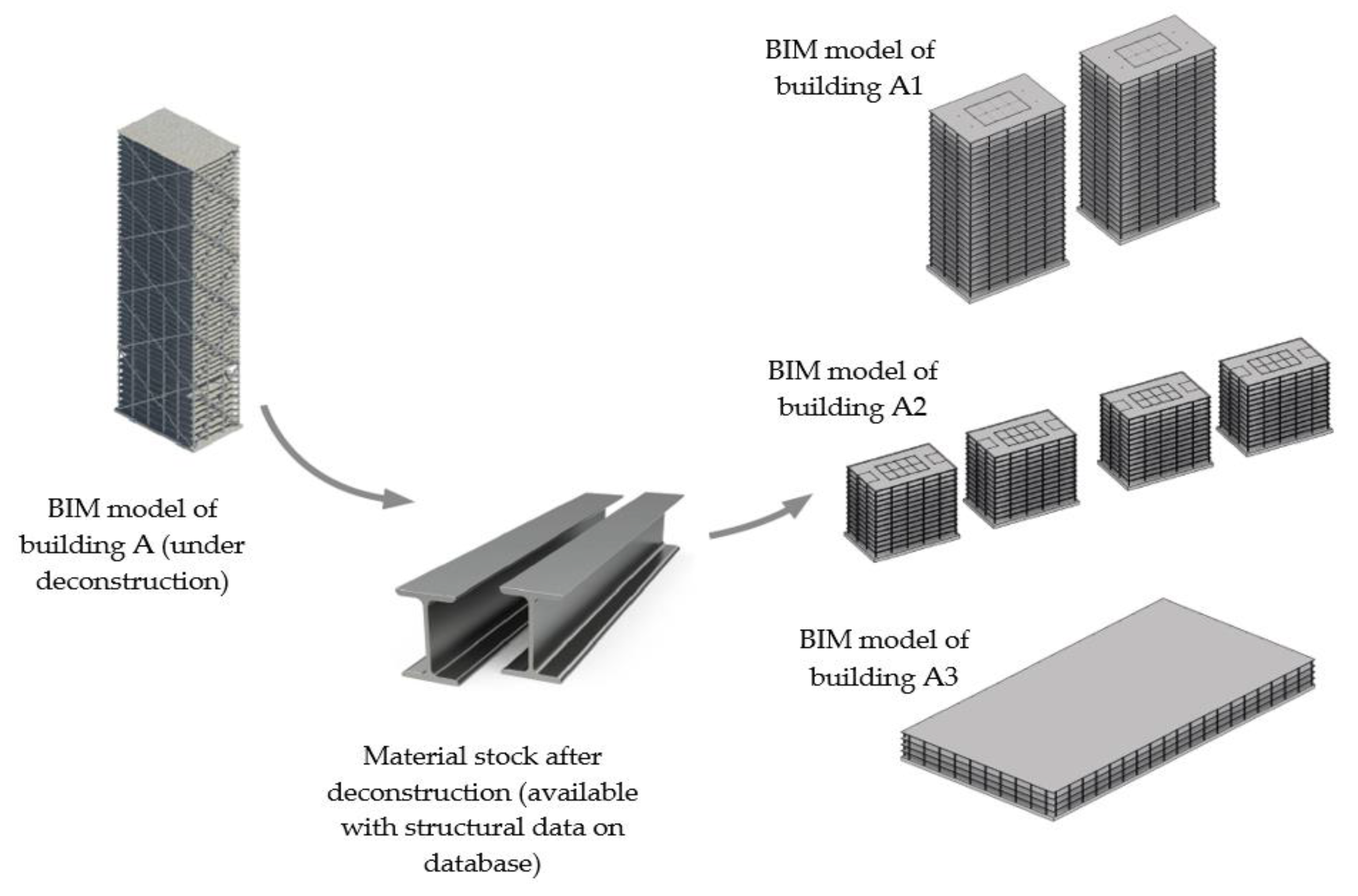
We first designed a reusable building (building A in Figure 4) to feed a bank of materials for future reuse. The typical building chosen (A) is a 41-story HRB in steel columns structure, which dimensioning corresponds to a typical program encountered in current practice and attempting to hinge as many elements as possible and evaluating its environmental impact. As seen above, the choice of HRB was made for its predisposition for reemployment. The scenario “design from a stock” made it possible to reconstitute various types, for example, A1, or A2 or A3 in Figure 4, of buildings using the entire stock of elements.
Therefore, we developed an application on a new building (building B in Figure 5) with the scenario “design with stock” trying to incorporate reusable elements of the material bank. We accompanied the process by the creation of BIM parameters necessary for the generation, traceability and management of critical information for reuse. The second building (B) integrating reused steel elements is a medium-high 18-story-high building, which may match with the new future French standard [68] of a flexible building (both offices and residential between 28 m and 50 m).
This first approach made it possible to identify all the steps to ensure reuse and, in this sense, allows a generalization. In this study, a BIM software and a database tool were chosen and used. The methodology described applies to any other BIM software and other types of databases.
4.1. Step 1: LCA
The whole building is the functional unit. To study the LCA impacts, we respected the NF EN 15804 [69]; the fixed scope is until the delivery on the construction site (A1–A3, according to EN 15804 [69]). Although LCA is a cradle to grave evaluation, further papers are limited to the production phase, [4,27,70]. In this study, we follow the same methodology. Furthermore, limits of scope are not the purpose of this study, since its objective is to demonstrate the application of the toolchain described in the methodology. The vast majority of impacts are related to the production and transportation of the elements. The choice of materials is decided long before the construction or deconstruction process.
4.2. Step 2: New BIM Parameters and LOD Framework for Load-Bearing Elements
The information previously identified and required for reuse was incorporated into the BIM model in the form of shared parameters (specific to the chosen BIM software) created specifically and for generalization. We also established a bill of materials to name these attributes. We must take a precaution so that the shared parameter is present during the IFC export, by specifying a value. An overview of the parameters created for a steel beam is shown in Table 1.
These newly created parameters make it possible to maintain exhaustive physical and mechanical characteristics. Ensuring the long-term traceability of these characteristics allows an engineer in 20- or 50-years’ time to have a perfect knowledge of the structural element and its capacities to put it back into operation in another building in complete safety. This traceability facilitates the EOL by avoiding an exhaustive resource diagnosis and/or the implementation of redhibitory characterization processes.
4.3. Step 3: Exportation Towards the Material Bank and Just-In-Time Circular Flow
After creating the necessary parameters for reuse, we transferred the information to a database. Then export of the structural and environmental parameters contained in the digital mockup to the chosen database, Microsoft SQL, is performed. A BIM software extension is developed in Visual Studio to export the parameters, and to create the first gateway between the model and the database. The realization of such an extension is possible thanks to the existence of the BIM software API. We detailed these developments in Figure 6. To retrieve all the information entered, the extension, developed entirely in C#, realizes a filter according to the existing category in BIM software: BuiltInCategory.OST_StructuralColumns, BuiltInCategory.OST_StructuralFraming, etc., using logical filters, LogicalOrFilter. In practice, buttons are created and integrated into the BIM software ribbon, so that pressing them produces what is called an external command.
The connection to Microsoft SQL is made directly in the BIM software extension, by writing parameters to the database. A division into several tables according to the type of the element (column, beam, sail or plate) is implemented when writing to the database.
This chain of tools could be generalized to an entire territory within the framework of political incentives such as the French government’s roadmap for a circular economy.
4.4. Step 4: Proof of Concept
The aim is to produce a functional toolchain that allows an exhaustive generalization afterwards. When a structural engineer designs a project, she/he models the load-bearing elements on finite element software to execute the calculation model. Thus, in our methodology, this finite element software is then used to query the database to find a reusable load-bearing element and to incorporate it into the model. The database hosts reuse elements that make up the materials bank. In this way, the model can now include reused elements and replace new elements.
Choosing a reused element means choosing an element that is oversized compared to the new one, either for lack of choice or for safety reasons. For this first request application, we established certain limitations. To prove that the proposed approach is feasible, we limit the ULS check to axial forces (pure traction and compression).
This method provides results for the two scenarios presented above. The scenario “design from a stock” allows reusing 100% of the elements by adjusting the design to the available stock. The possible variants have the following characteristics in Table 2.
We made adjustments to the toolchain for the scenario “design with a stock”. We developed an algorithm to perform a database query that allows the comparison between the stock table and the results (of the constraints determined in the building being designed). We then evaluated the best choice for replacing the columns of the model (of the building being designed) with reused elements. During a query, the user can determine the margin of tolerance. The user enters a value to fix the allowable difference between the length of the stored columns and the theoretical length of the columns being designed. It is also possible to fix the acceptable difference between the theoretical capacities and the real one in stock for pure compression. As a result, most of the reused elements are slightly oversized concerning the strength requested in the theoretical calculation of the building being designed. The allowable values also limit material waste or over-consumption. As soon as the allowable limits are input, the algorithm starts.
The algorithm runs through each pole in the stock table, comparing it with each pole in the model, analyzing whether or not the allowable limits have been met. Therefore, several iterations are to be expected to take into account the change. Thus, as the building mass changes, then we need to recalculate the loads. As this situation will be frequent, the tool developed in this study allows the user to set the tolerances on the dimensional and load-bearing capacity overruns of the elements to retain. In our case, we proposed a progressive increase of the acceptable margin for the capacity of the reused elements, to maximize numbers of reused columns (from the deconstructed HRB A). The final acceptable value is +110% for the allowed capacity difference of the reuse elements. The results of the application are presented in Table 3 and Table 4.
In our example, the stock of columns to be reused from the HRB is very limited but it is possible to reuse 8 columns among 420 columns constituting the building B. Oversizing was limited to keep elements with a reasonable size for this case study, but this criterion is questionable. However, the limited stock relating to a single original building is not suitable for a new “Design with a stock” scenario. The new reversible medium-high building standard has spans and ceiling heights that require particular load-bearing elements. A more classical building with the same office function would be able to integrate more reused elements. However, an enlarged and generalized stock for territory would allow a more excellent choice and would avoid such a considerable oversizing. Despite this significant oversizing of +12% in mass, there is a gain on environmental impacts, compared to a new variant of Building B.
When the final structure integrating a maximum of reused elements is fixed, new modeling on the software can be carried out and, in turn, feed the material bank database.
This proof of concept shows that a generalized reuse policy must be accompanied by new design standards such as identical ceiling height and span for offices and housing. Thus, a load-bearing element will be able to correspond to several types of programs (offices, housing) and will be more easily reusable in a large number of future buildings.
Without these new design paradigms, reuse can only concern a small part of the stock (“design with a stock” scenario). This is why it is highly preferable to generalize the concept of "design from a stock" as a new standard to reach 100% of reused load-bearing elements.
5. Discussion
This study sets up the tool suite to allow the transfer of structural properties between the BIM modeling software, the structural calculation software and a database hosting the ready-to-reuse materials bank. The accuracy of the properties attached to the BIM objects allows us to perform a finer LCA. With this toolchain and the database, the structural engineer’s competence is now to control and reduce the environmental impact. Two cases are to be apprehended: the restrictive database or the almost unlimited database. In the case of the massification of reuse, the unlimited database is plausible and expected. The establishment of such a bank at the national level would generate a supply of materials more compatible with the real demand for current projects. Different points are discussed in the following parts.
5.1. Embodied Carbon and Scope Extension
Previous studies have mentioned targets to reduce GHG emissions in construction [71] through reuse and recycling. We have shown that reuse reduces GHG emissions more drastically than recycling (“design from a stock” scenario) and that efforts must continue to generalize reuse before recycling. The past studies showed that the embodied carbon is mainly due to the elements composing the load-bearing system in a building. This is why this study focused on the impact and reuse of these elements. However, an in-depth look at these studies to extend the scope to other building components, as well as technical equipment, is necessary for a more generalized application without neglecting secondary impacts. Other studies have chosen to focus on the reuse of a building as a whole and reconversion [72]. Reconversion allows for a massive conversation of the material already implemented. Our research promotes change in our current construction methods and facilitates these building reconversions thanks to a better dismantling.
5.2. Database Maintenance
This article introduced a parametric BIM-workflow and database that should be accessible and interoperable throughout the lifetime of the buildings, up to hundreds of years. Software maintenance during such a long period is a critical issue, as there is little return on experience on this topic in the construction industry. However, some industries are already facing these challenges. For example, on-board software in a spacecraft or an extra-terrestrial rover should remain operational at any time, which brings the obligation to assemble a team devoted to software maintenance [73]. The cost of such maintenance cannot be avoided in the reuse of buildings and may be very high in the long run. Two main options are available:
- First, the BIM model and database are based on an open-source core with interoperability done by private companies. Maintenance is performed in an open and collaborative framework.
- Second, the BIM model and database rely fundamentally on proprietary software. Private actors perform maintenance.
Both options have their advantages and associated risks. For open-source solutions, the appearance of different branches is highly likely for a long-term project, which means that interoperability in practice becomes harder and harder to achieve. For proprietary solutions, this issue is less problematic, but the appearance of a monopolistic private software editor taking maintenance in charge is a risk that cannot be neglected.
Finally, the central learning from this remark is that the BIM-Workflow and database should remain as simple as possible, to ease maintenance. The inflation of BIM complexity should be regarded with concern, as it also has an environmental impact that is not yet evaluated. In essence, the data necessary to the implementation of a deconstruction scheme should be stored safely, possibly on servers in different locations, and remain accessible to project teams in a distant future.
5.3. BIM-LCA Workflows and Generative Design
Recent studies have dealt with the automation of the exchanges between BIM and LCA, allowing a reactive LCA to design changes. But the lack of data for initial LCA approaches during the early phases of a project needs to be improved. In general, better interoperability between all BIM and LCA software is still expected [10,30,74]. BIM is a data source for LCA—and in the same way that parametric design has been developed for design—a parametric LCA [75] would be linked to the BIM model to enable immediate consideration of model changes in terms of environmental impacts. In this way, we could estimate the impact of different structural design options. Developments to integrate deconstruction plans with long-term tracked data would facilitate the anticipation of reuse. [46,57]. There is also a part of a lack of adequate information and uncertainties about future technologies, which complicates scenarios based on high information traceability. Most researches have focused on the impact of climate change [26], but the set of LCA impact indicators now needs to be developed to avoid pollution displacements.
5.4. Evolution of LCA
The LCA applied in this study is based on standard NF EN 15804-A1 [69]. Additional indicators to better evaluate reuse are expected. The time parameter remains a missing parameter for the moment. Thus, the aspect of material aging and their monitoring would allow a better evaluation of reusability and residual lifetime in real-time to control life cycle durations better. Monitoring linked to the LCA tool would enable the evolution or degradation of the material at the different stages of its life cycle [62]. EOL scenarios could be integrated better into the LCA to anticipate reuse and obtain more easily the impacts according to the different reuse operations envisaged conceptually. The problem of anticipation also lies in the uncertainty linked to the long term, which is difficult to take into account upstream.
Similarly, we could not explore the impact deconstruction phase of reuse due to a lack of data. It is both very time-consuming and very uncertain to include the impact on construction sites in LCAs. This is why a methodology integrating the notion of prospective scenarios with an estimate of the impact of the construction phase would allow the first approach in order not to neglect this impact. Other studies have chosen to focus on the creation of sustainability indicators [76] to complement the LCA tool. We can include the reuse and its specifications among these indicators.
6. Conclusions and Perspective
This study has demonstrated the practical application of reuse through applied case studies with a suite of tools and constitute guidelines for practitioners. The constructive arrangements and structure typology feed the design for reuse (DfReu) concept, which is also based on a BIM framework and complete traceability defined in this study.
The study is limited for the time being to the use of passive data, i.e., data entered during the design and execution phases. A certain number of data are variables during the life of the structure, and other data are generated during the operation phase. Thus, the methodology did not integrate the possibility of having data emitted by sensors, for example. Another challenge is to link data from data acquisition systems, sensors, laser scan, drones, during the monitoring of buildings to evaluate the real-time impacts. Moreover, due to the lack of data collected on construction and deconstruction processes, the link with real-time interactive LCA could not be developed. Concerning the data identified in the study, the implementation of a quality control process at the national level, with insurers, in particular, would make it possible to specify the devices chosen (number of RFID chips per element, type of data protection, etc.) to develop professional construction rules.
This study is already leading to the recommendation of new standards. Thus, construction policies will be able to favor the implementation of a specific type of structure for high-rise buildings, offices and housing (determination of span, height under ceiling) both to reduce environmental impacts during construction and also during deconstruction to reuse. The toolchain presented and tested in this paper can be extended to a national practice in order also to benefit from a territory-wide pooled stock of elements.
Moreover, this process is generalizable and adaptable for all BIM software, which would give more extensive access to the methodology proposed in this paper.
The generalization of the stock would also increase the number of elements available for reuse.
We had to make simplifications in terms of queries for the calculation model. The next part of the research is to make possible queries integrating more complex requests (such as compound bending).
Another avenue for our future research is an adaptation of the LOD and LOI 600 and 700 of the BIM to LCA. Thus, a correlation between the BIM data of the project with their respective LOI levels in terms of environmental information and the data in the LCA database could generate LCA levels in first approaches at the beginning of the design. Subsequently, LOI for the EPDs would allow us to specify the environmental impacts progressively before a final comprehensive LCA. Further research on LCA LOIs is needed as well as structural design principles that maximize reuse from the early stages of a project.
Future research to assess the impact of the construction and deconstruction phase of different types of structures has also been initiated in this paper. For this purpose, a large amount of data needs to be acquired. We also need experimental construction sites, with involved clients to encourage all stakeholders to measure, control, and capitalize on environmental data (such as time of use of construction machines).
Author Contributions
Conceptualization, I.B., R.M., J.-M.J. and R.L.R.; methodology, I.B. and R.M.; software, I.B. and R.M.; validation, I.B., R.M., J.-M.J., A.F., and R.L.R.; formal analysis, I.B.; investigation, I.B.; data curation, I.B.; writing—original draft preparation, I.B.; writing—review and editing, I.B. and R.M.; visualization, I.B. and R.M.; supervision, R.M., J.-M.J., A.F. and R.L.R.; project administration, J.-M.J., A.F., R.L.R. All authors have read and agreed to the published version of the manuscript.
Funding
This work was made during Ms. Bertin’s doctorate within the framework of an industrial agreement for training through research (CIFRE number 2017/0471) jointly financed by the company Setec TPI and the National Association for Research and Technology (ANRT) of France.
Acknowledgments
Cristina Alexan for her contribution to gateways development and Clément Boudet for his BIM support.
Conflicts of Interest
The authors declare no conflict of interest.
Abbreviations
| BIM | Building Information Modeling |
| CDW | Construction and Demolition Waste |
| CE | Circular Economy |
| DfD | Design for Deconstruct |
| DfReu | Design for Reuse |
| EC | Embodied Carbon |
| EE | Embodied Energy |
| EOL | End of Life |
| FRP | Fiber Reinforced Polymer |
| HBR | High-Rise Building |
| GHGs | Greenhouse gases |
| IFC | Industry Foundation Classes |
| IPPC | Intergovernmental Panel on Climate Change |
| LCA | Life Cycle Assessment |
| LCI | Life Cycle Inventory |
| OECD | Organization for Economic Co-operation and Development |
| RFID | Radio Frequency Identification |
| RIBA | Royal Institute of British Architects |
| SHM | Structural health monitoring |
Appendix A

Table A1.
Detailed properties of the new LOD/LOI for load-bearing systems.
| LOD/LOI of 6D BIM | Element Static Properties | Element Mechanical Properties | Overall Structural Behavior Properties | Reuse Process Properties |
|---|---|---|---|---|
| 100: Concept Design | geometry, resistance class, relevant standard | position, approximate type of loads, | exposure class | |
| 200: Developed Design | Geometry (length, cross section), approximate composition (weight, Young’s moduli, densities, mass inertia, Poisson’s ratio), resistance class, relevant standard | position, type of loads, nominal loading capacity, stress applied, | exposure class | |
| 300: Technical Design | Geometry (length, cross section), detailed composition (weight, Young’s moduli, densities, mass inertia, Poisson’s ratio), resistance class, relevant standard | position, type of loads, nominal loading capacity, stress applied, connection conditions, creep, ultimate normal effort | exposure class, approximate differential shortening, approximate soil compaction, approximate differential displacements between floors, scaling criterion, | anticipated deconstruction phasing, environmental impact (EPD), theorical service life |
| 400: Construction | Geometry (length, cross section), detailed composition (weight, Young’s moduli, densities, mass inertia, Poisson’s ratio), resistance class, relevant standard | position, type of loads, nominal loading capacity, stress applied, connection conditions, creep, ultimate normal effort | exposure class, detailed differential shortening, detailed soil compaction, detailed top displacement, detailed top acceleration, detailed differential displacements between floors, scaling criterion | anticipated deconstruction phasing, environmental impact (EPD), theorical service life, exit scenario |
| 500: As Built | Geometry (length, cross section), real composition, resistance class, relevant standard | Real position, type of loads, nominal loading capacity, stress applied, detailed connection, creep, ultimate normal effort, aging characteristics | exposure class, real differential shortening, real soil compaction, real top displacement, real top acceleration, real differential displacements between floors, scaling criterion | checks required at EOL, anticipated deconstruction phasing, hosting on the digital material bank environmental impact (EPD), theorical service life, exit scenario, anticipated probabilities of failure |
| 600: In Use | Damages on element (impacts, chemical attacks, corrosion, fatigue degradation, rust formation and plasticization,), component replacement | monitoring the aging of the materials and the data obtained by the monitoring system | exposure class, differential shortening, soil compaction, top displacement, top acceleration, differential displacements between floors, scaling criterion, useful life of structure and damages (storm, fire, earthquakes, heavy snow, high and low temperatures, coastal or marine environments) | |
| 700: Deconstruction and Reuse | Checks between theoretical data and physically traced data | Checks between theoretical data and physically and monitoring traced data checks of aging characteristics | Checks between theoretical data and monitoring (frequency and duration of loading, displacements) traced data | Checks required and protocol, characterization test, residual performance tests, probabilities of failure, deconstruction phasing (transport and reuse or disposal scenario), element availability, LCA of deconstruction process, remaining lifespan estimation |
References
- IPCC. 2018: Summary for Policymakers. In Global Warming of 1.5°C; IPCC: Genève, Switzerland, 2018; Available online: https://www.ipcc.ch/site/assets/uploads/sites/2/2019/05/SR15_SPM_version_report_LR.pdf (accessed on 8 October 2019).
- Brütting, J.; De Wolf, C.; Fivet, C. The reuse of load-bearing components. IOP Conf. Series Earth Environ. Sci. 2019, 225, 8. [Google Scholar] [CrossRef]
- Brütting, J.; Senatore, G.; Fivet, C. Optimization Formulations for the Design of Low Embodied Energy Structures Made from Reused Elements. In Lecture Notes in Computer Science; Springer: Cham, Switzerland, 2018. [Google Scholar]
- Brütting, J.; Desruelle, J.; Senatore, G.; Fivet, C. Design of Truss Structures Through Reuse. Structures 2019, 18, 128–137. [Google Scholar] [CrossRef]
- Iacovidou, E.; Purnell, P. Mining the physical infrastructure: Opportunities, barriers and interventions in promoting structural components reuse. Sci. Total. Environ. 2016, 557, 791–807. [Google Scholar] [CrossRef] [PubMed] [Green Version]
- Hoxha, E.; Habert, G.; Lasvaux, S.; Chevalier, J.; Le Roy, R. Influence of construction material uncertainties on residential building LCA reliability. J. Clean. Prod. 2017, 144, 33–47. [Google Scholar] [CrossRef]
- OECD HIGHLIGHTS Global Material Resources Outlook to 2060—Economic Drivers and Environmental Consequences, October 2018. Available online: https://www.oecd.org/environment/waste/highlights-global-material-resources-outlook-to-2060.pdf (accessed on 8 October 2019).
- Dixit, M.; Fernandez-Solis, J.L.; Lavy, S.; Culp, C.H. Identification of parameters for embodied energy measurement: A literature review. Energy Build. 2010, 42, 1238–1247. [Google Scholar] [CrossRef]
- Di Bari, R.; Jorgji, O.; Horn, R.; Gantner, J.; Ebertshäuser, S. Step-by-step implementation of BIM-LCA: A case study analysis associating defined construction phases with their respective environmental impacts. In Proceedings of the SBE D-A-CH 19 IOP Conf. Ser. 323, Graz, Austria, 11–14 September 2019; IOP Science: Bristol, UK, 2019; Volume 323, p. 012105. [Google Scholar] [CrossRef]
- Santos, R.; Costa, A.A.; Silvestre, J.D.; Pyl, L. Informetric analysis and review of literature on the role of BIM in sustainable construction. Autom. Constr. 2019, 103, 221–234. [Google Scholar] [CrossRef]
- CITEPA. Réaliser Une Analyse Environnementale, Guide sectoriel 2015. Available online: http://bilansges.ademe.fr/docutheque/docs/guide%20finalis%C3%A9e%20FNTP%20avril%202015.pdf (accessed on 29 November 2017).
- Crippa, J.; Boeing, L.C.; Caparelli, A.P.A.; Costa, M.D.R.D.M.M.D.; Scheer, S.; Araujo, A.M.F.; Bem, D. A BIM–LCA integration technique to embodied carbon estimation applied on wall systems in Brazil. Built Environ. Proj. Asset Manag. 2018, 8, 491–503. [Google Scholar] [CrossRef]
- Habert, G.; Arribe, D.; Dehove, T.; Espinasse, L.; Le Roy, R. Reducing environmental impact by increasing the strength of concrete: Quantification of the improvement to concrete bridges. J. Clean. Prod. 2012, 35, 250–262. [Google Scholar] [CrossRef]
- Nilsen, M.; Bohne, R.A. Evaluation of BIM based LCA in early design phase (low LOD) of buildings. In Proceedings of the SBE D-A-CH 19 IOP Conf. Ser. 323, Graz, Austria, 11–14 September 2019; IOP Science: Bristol, UK, 2019; p. 012119. [Google Scholar] [CrossRef]
- Eleftheriadis, S.; Mumovic, D.; Greening, P. Life cycle energy efficiency in building structures: A review of current developments and future outlooks based on BIM capabilities. Renew. Sustain. Energy Rev. 2017, 67, 811–825. [Google Scholar] [CrossRef] [Green Version]
- Ibrahim, M.I.M. Estimating the sustainability returns of recycling construction waste from building projects. Sustain. Cities Soc. 2016, 23, 78–93. [Google Scholar] [CrossRef]
- Kiss, B.; Röck, M.; Passer, A.; Szalay, Z. A cross-platform modular framework for building Life Cycle Assessment. IOP Conf. Ser. Earth Environ. Sci. 2019, 323, 012103. [Google Scholar] [CrossRef] [Green Version]
- Cai, G.; Waldmann, D. A material and component bank to facilitate material recycling and component reuse for a sustainable construction: Concept and preliminary study. Clean Technol. Environ. Policy 2019, 21, 2015–2032. [Google Scholar] [CrossRef]
- Lismont, A.; Allacker, K. Turning the existing building stock into a resource mine: Proposal for a new method to develop building stock models. In Proceedings of the SBE D-A-CH 19 IOP Conf. Ser. 323, Graz, Austria, 11–14 September 2019; IOP Science: Bristol, UK, 2019; p. 012070. [Google Scholar] [CrossRef] [Green Version]
- Rios, F.C.; Chong, W.K.; Grau, D. Design for Disassembly and Deconstruction—Challenges and Opportunities. Procedia Eng. 2015, 118, 1296–1304. [Google Scholar] [CrossRef] [Green Version]
- Hamidi, B.; Bulbul, T. A Comparative Analysis of Sustainable Approaches to Building End-of-Lifecycle: Underlying Deconstruction Principles in Theory and Practice. In Proceedings of the International Conference on Sustainable Design, Engineering, and Construction, Fort Worth, TX, USA, 7–9 November 2012; ASCE Library: Reston, VA, USA, 2013; pp. 155–162. [Google Scholar] [CrossRef]
- Kasthurba, A.K.; Reddy, K.R.; Venkat Reddy, D. Sustainable Approaches for Utilizing Waste in Building Construction: Two Case Studies in India. Int. J. Earth Sci. Eng. 2014, 7, 838–844. [Google Scholar]
- Ali Jalil, Z.; Naji, H.I.; Mahmood, M.S. Developing Sustainable Alternatives from Destroyed Buildings Waste for Reconstruction Projects. Civ. Eng. J. 2020, 6, 60–68. [Google Scholar] [CrossRef]
- Lankhorst, G.J.; Arts, J.; Terwel, K.C.; Jonkers, H.M. Life Cycle Analysis: Load-Bearing Structures of High-Rise Buildings in Western Europe. CTBUH J. 2019, 3, 28–35. [Google Scholar]
- Cavalliere, C.; Habert, G.; Dell’Osso, G.R.; Hollberg, A. Continuous BIM-based assessment of embodied environmental impacts throughout the design process. J. Clean. Prod. 2019, 211, 941–952. [Google Scholar] [CrossRef]
- Marzouk, M.; Abdelkader, E.M.; Al-Gahtani, K.; Ahmed, E. Building information modeling-based model for calculating direct and indirect emissions in construction projects. J. Clean. Prod. 2017, 152, 351–363. [Google Scholar] [CrossRef]
- Kaethner, S.C.; Burridge, J.A. Embodied CO2 of structural frames. Struct. Eng. 2012, 90, 33–40. [Google Scholar]
- Veselka, J.; Růžička, J.; Lupíšek, A.; Hájek, P.; Mančík, S.; Žďára, V.; Široký, M. Connecting BIM and LCA: The Case Study of an Experimental Residential Building. In Proceedings of the SBE D-A-CH 19 IOP Conf. Ser. 323, Graz, Austria, 11–14 September 2019; IOP Science: Bristol, UK, 2019; p. 012106. [Google Scholar] [CrossRef]
- Anderson, J.E.; Silman, R. A Life Cycle Inventory of Structural Engineering Design Strategies for Greenhouse Gas Reduction. Struct. Eng. Int. 2009, 19, 283–288. [Google Scholar] [CrossRef]
- Wong, J.K.W.; Zhou, J. Enhancing environmental sustainability over building life cycles through green BIM: A review. Autom. Constr. 2015, 57, 156–165. [Google Scholar] [CrossRef]
- Fivet, C. Design of Load-Bearing Systems for Open-Ended Downstream Reuse. In Proceedings of the SBE19 Brussels BAMB-CIRCPATH IOP Conf. Series: Earth and Environmental Science 225, Brussels, Belgium, 5–7 February 2019; IOP Science: Bristol, UK, 2019; p. 012031. [Google Scholar] [CrossRef]
- Akadiri, P.O.; Chinyio, E.A.; Olomolaiye, P.O. Design of A Sustainable Building: A Conceptual Framework for Implementing Sustainability in the Building Sector. Buildings 2012, 2, 126–152. [Google Scholar] [CrossRef] [Green Version]
- Bertin, I.; Lebrun, F.; Braham, N.; Le Roy, R. Construction, deconstruction, reuse of the structural elements: The circular economy to reach zero carbon. In Proceedings of the SBE D-A-CH 19 IOP Conf. Ser. 323, Graz, Austria, 11–14 September 2019; IOP Science: Bristol, UK, 2019; p. 012020. [Google Scholar] [CrossRef] [Green Version]
- ISO 14040:2006. Environmental Management—Life Cycle Assessment—Principles and Framework; International Standardisation Organisation: Geneva, Switzerland, 2006. [Google Scholar]
- Slobodchikov, R.; Lohne Bakke, K.; Ragnar Svennevig, P.; O’Born, R. Implementing climate impacts in road infrastructure in the design phase by combining BIM with LCA. In Proceedings of the SBE D-A-CH 19 IOP Conf. Ser. 323, Graz, Austria, 11–14 September 2019; IOP Science: Bristol, UK, 2019; p. 012089. [Google Scholar] [CrossRef]
- ISO 14044:2006. Environmental Management—Life Cycle Assessment—Requirements and Guidelines; International Standardisation Organisation: Geneva, Switzerland, 2006. [Google Scholar]
- Nizam, R.S.; Zhang, C.; Tian, L. A BIM based tool for assessing embodied energy for buildings. Energy Build. 2018, 170, 1–14. [Google Scholar] [CrossRef]
- Najjar, M.K.; Figueiredo, K.; Palumbo, M.; Haddad, A.N. Integration of BIM and LCA: Evaluating the environmental impacts of building materials at an early stage of designing a typical office building. J. Build. Eng. 2017, 14, 115–126. [Google Scholar] [CrossRef]
- Yung, P.; Wang, X. A 6D CAD Model for the Automatic Assessment of Building Sustainability. Int. J. Adv. Robot. Syst. 2014, 11, 131. [Google Scholar] [CrossRef] [Green Version]
- Vandervaeren, C.; Galle, W.; De Temmerman, N. Parametric life cycle assessment of a reusable brick veneer. In Proceedings of the SBE D-A-CH CONFERENCE 2019 IOP Conf. Ser. 323, Graz, Austria, 11–14 September 2019; IOP Science: Bristol, UK, 2019; p. 012137. [Google Scholar] [CrossRef]
- Won, J.; Cheng, J.C.P. Identifying potential opportunities of building information modeling for construction and demolition waste management and minimization. Autom. Constr. 2017, 79, 3–18. [Google Scholar] [CrossRef]
- Liu, Z.; Osmani, M.; Demian, P.; Baldwin, A. A BIM-aided construction waste minimisation framework. Autom. Constr. 2015, 59, 1–23. [Google Scholar] [CrossRef] [Green Version]
- Bilal, M.; Oyedele, L.O.; Akinade, O.; Ajayi, S.; Alaka, H.A.; Owolabi, H.A.; Qadir, J.; Pasha, M.; Bello, S.A. Big data architecture for construction waste analytics (CWA): A conceptual framework. J. Build. Eng. 2016, 6, 144–156. [Google Scholar] [CrossRef]
- Akinade, O.; Oyedele, L.O.; Bilal, M.; Ajayi, S.; Owolabi, H.A.; Alaka, H.A.; Bello, S.A. Waste minimisation through deconstruction: A BIM based Deconstructability Assessment Score (BIM-DAS). Resour. Conserv. Recycl. 2015, 105, 167–176. [Google Scholar] [CrossRef]
- Akanbi, L.A.; Oyedele, L.O.; Akinade, O.; Ajayi, A.O.; Delgado, M.D.; Bilal, M.; Bello, S.A. Salvaging building materials in a circular economy: A BIM-based whole-life performance estimator. Resour. Conserv. Recycl. 2018, 129, 175–186. [Google Scholar] [CrossRef]
- Akinade, O.; Oyedele, L.O.; Omoteso, K.; Ajayi, S.O.; Bilal, M.; Owolabi, H.A.; Alaka, H.A.; Ayris, L.; Looney, J.H. BIM-based deconstruction tool: Towards essential functionalities. Int. J. Sustain. Built Environ. 2017, 6, 260–271. [Google Scholar] [CrossRef]
- Lee, S.; Tae, S.; Roh, S.; Kim, T. Green Template for Life Cycle Assessment of Buildings Based on Building Information Modeling: Focus on Embodied Environmental Impact. Sustainability 2015, 7, 16498–16512. [Google Scholar] [CrossRef] [Green Version]
- Ilhan, B.; Yaman, H. Green building assessment tool (GBAT) for integrated BIM-based design decisions. Autom. Constr. 2016, 70, 26–37. [Google Scholar] [CrossRef]
- Forth, K.; Braun, A.; Borrmann, A. BIM-integrated LCA - model analysis and implementation for practice. In Proceedings of the SBE D-A-CH 19 IOP Conf. Ser. 323, Graz, Austria, 11–14 September 2019; IOP Science: Bristol, UK, 2019; p. 012100. [Google Scholar] [CrossRef]
- Lu, Y.; Wu, Z.; Chang, R.; Li, Y. Building Information Modeling (BIM) for green buildings: A critical review and future directions. Autom. Constr. 2017, 83, 134–148. [Google Scholar] [CrossRef]
- BIMFORUM. LEVEL OF DEVELOPMENT (LOD) SPECIFICATION PART I COMMENTARY, April 2019. Available online: https://bimforum.org/wp-content/uploads/2019/04/LOD-Spec-2019-Part-I-and-Guide-2019-04-29.pdf (accessed on 9 January 2020).
- Ganter, M.; Lützkendorf, T. Information management throughout the life cycle of buildings—Basics and new approaches such as blockchain. In Proceedings of the SBE D-A-CH 19 IOP Conf. Ser. 323, Graz, Austria, 11–14 September 2019; IOP Science: Bristol, UK, 2019; p. 012110. [Google Scholar] [CrossRef] [Green Version]
- Röck, M.; Hollberg, A.; Habert, G.; Passer, A. LCA and BIM: Visualization of environmental potentials in building construction at early design stages. Build. Environ. 2018, 140, 153–161. [Google Scholar] [CrossRef]
- Röck, M.; Passer, A.; Ramon, D.; Allacker, K. The coupling of BIM and LCA—Challenges identified through case study implementation. In Proceedings of the Sixth International Symposium on Life-Cycle Civil Engineering, Ghent, Belgium, 28–31 October 2018; Caspeele, R., Taerwe, L., Frangopol, D.M., Eds.; CRC Press: Boca Raton, FL, USA, 2018; pp. 841–846. [Google Scholar]
- Figl, H.; Ilg, M.; Battisti, K. 6D BIM–Terminal: Missing Link for the design of CO2-neutral buildings. In Proceedings of the SBE D-A-CH 19 IOP Conf. Ser. 323, Graz, Austria, 11–14 September 2019; IOP Science: Bristol, UK, 2019; p. 012104. [Google Scholar] [CrossRef] [Green Version]
- Cavalliere, C.; Hollberg, A.; Dell’Osso, G.; Habert, G. Consistent BIM-led LCA during the entire building design process. In Proceedings of the SBE D-A-CH 19 IOP Conf. Ser. 323, Graz, Austria, 11–14 September 2019; IOP Science: Bristol, UK, 2019; p. 012099. [Google Scholar] [CrossRef]
- Akinade, O.; Oyedele, L.O.; Ajayi, S.; Bilal, M.; Alaka, H.A.; Owolabi, H.A.; Bello, S.A.; Jaiyeoba, B.E.; Kadiri, K.O. Design for Deconstruction (DfD): Critical success factors for diverting end-of-life waste from landfills. Waste Manag. 2017, 60, 3–13. [Google Scholar] [CrossRef]
- Wastiels, L.; Decuypere, R. Identification and comparison of LCA-BIM integration strategies. In Proceedings of the SBE D-A-CH 19 IOP Conf. Ser. 323, Graz, Austria, 11–14 September 2019; IOP Science: Bristol, UK, 2019; p. 012101. [Google Scholar] [CrossRef] [Green Version]
- Shadram, F.; Johansson, T.; Lu, W.; Schade, J.; Olofsson, T. An integrated BIM-based framework for minimizing embodied energy during building design. Energy Build. 2016, 128, 592–604. [Google Scholar] [CrossRef]
- Lu, K.; Jiang, X.; Tam, V.W.Y.; Li, M.; Wang, H.; Xia, B.; Chen, Q. Development of a Carbon Emissions Analysis Framework Using Building Information Modeling and Life Cycle Assessment for the Construction of Hospital Projects. Sustainability 2019, 11, 6274. [Google Scholar] [CrossRef] [Green Version]
- Cavalliere, C.; Raffaele Dell’Osso, G.; Pierucci, A.; Iannone, F. Life cycle assessment data structure for building information modelling. J. Clean. Prod. 2018, 199, 193–204. [Google Scholar] [CrossRef]
- Iacovidou, E.; Purnell, P.; Lim, M.K. The use of smart technologies in enabling construction components reuse: A viable method or a problem creating solution? J. Environ. Manag. 2017, 216, 214–223. [Google Scholar] [CrossRef]
- The RIBA Plan of Work. 2013. Available online: https://www.ribaplanofwork.com/About/Concept.aspx (accessed on 17 December 2019).
- BS France-Mediaconstruct, Notions Clés du BIM. Available online: https://www.buildingsmartfrance-mediaconstruct.fr/definition-notions-bim/ (accessed on 20 September 2019).
- ISO 29481-1:2016, Building Information Models—Information Delivery Manual—Part 1: Methodology and Format; International Standardisation Organisation: Geneva, Switzerland, 2016.
- ISO 19650:2018, Organization and Digitization of Information about Buildings and Civil Engineering Works, Including Building Information Modelling (BIM)—Information Management Using Building Information Modelling; International Standardisation Organisation: Geneva, Switzerland, 2018.
- Singapour, « Banc D’essai » de la Ville Digitale. Available online: https://www.lemonde.fr/smart-cities/article/2016/11/23/singapour-banc-d-essai-de-la-ville-digitale_5036699_4811534.html (accessed on 13 November 2019).
- Pending Decree. (n°2018-1021), Loi ELAN du 23 novembre 2018.
- NF EN 15804+A1 April 2014, Sustainability of Construction Works—Environmental Product Declarations—Core Rules for the Product Category of Construction Products; AFNOR, French Standardization Association, La Plaine Saint-Denis: Saint-Denis, France, 2014.
- Eleftheriadis, S.; Duffour, P.; Mumovic, D. BIM-embedded life cycle carbon assessment of RC buildings using optimised structural design alternatives. Energy Build. 2018, 173, 587–600. [Google Scholar] [CrossRef]
- Burciaga, U.M.; Sáez, P.V.; Ayón, F.J.H. Strategies to Reduce CO2 Emissions in Housing Building by Means of CDW. Emerg. Sci. J. 2019, 3, 274–284. [Google Scholar] [CrossRef] [Green Version]
- Zavadskas, E.K.; Antuchevičienė, J. Multiple criteria evaluation of rural building’s regeneration alternatives. Build. Environ. 2007, 42, 436–451. [Google Scholar] [CrossRef]
- Shell, E.; Lue, Y.; Chu, M.I. Spacecraft Onboard Software Maintenance—An Effective Approach which Reduces Costs and Increases Science Return. In Reducing the Cost of Spacecraft Ground Systems and Operations. Space Technology Proceedings; Miau, J.J., Holdaway, R., Eds.; Springer: Dordrecht, The Netherlands, 2000; Volume 3, ISBN 978-94-015-9395-3. Print ISBN 978-90-481-5400-5. [Google Scholar]
- Chong, H.-Y.; Lee, C.Y.; Wang, X. A mixed review of the adoption of Building Information Modelling (BIM) for sustainability. J. Clean. Prod. 2017, 142, 4114–4126. [Google Scholar] [CrossRef] [Green Version]
- Oti, A.H.; Tizani, W.; Abanda, F.; Jaly-Zada, A.; Tah, J. Structural sustainability appraisal in BIM. Autom. Constr. 2016, 69, 44–58. [Google Scholar] [CrossRef]
- Loo, L.D.; Mahdavinejad, M. Analysis of Design Indicators of Sustainable Buildings with an Emphasis on Efficiency of Energy Consumption (Energy Efficiency). Civ. Eng. J. 2018, 4, 897. [Google Scholar] [CrossRef] [Green Version]
Figure 1.
Research methodology.

Figure 2.
Levels of detail or development (LODs) established, and proposal for a LOD 600 and a LOD 700 applied to structural elements (based on RIBA [63] plan of work for the design stages).
Figure 2.
Levels of detail or development (LODs) established, and proposal for a LOD 600 and a LOD 700 applied to structural elements (based on RIBA [63] plan of work for the design stages).

Figure 3.
Toolchain used to implement the material bank, from BIM models, material platforms and environmental data.
Figure 3.
Toolchain used to implement the material bank, from BIM models, material platforms and environmental data.

Figure 4.
Scenario “design from a stock” with reconstruction applied from an initial high-rise buildings (HRB) elements stock, for which we developed the workflows using the toolchain.
Figure 4.
Scenario “design from a stock” with reconstruction applied from an initial high-rise buildings (HRB) elements stock, for which we developed the workflows using the toolchain.

Figure 5.
Scenario “design with a stock” with reconstruction applied from an initial HRB towards a new medium-high building, for which we developed the workflows using the toolchain.
Figure 5.
Scenario “design with a stock” with reconstruction applied from an initial HRB towards a new medium-high building, for which we developed the workflows using the toolchain.

Figure 6.
Synthesis of Gateways with calculation model.

Table 1.
Application of the nomenclature to a steel beam named “BEAMS - STR_BEA_HEM”.
| Attribute | Attribute Type | Group | Application |
|---|---|---|---|
| Section: BEA_width | Length | Dimensions | Type |
| Section: BEA_height | Length | Dimensions | Type |
| Web plate area | Area | Structural analysis | Type |
| Steel composition (including weldability) | Text | Materials and finishing | Type |
| Steel designation (grade and quality including Re and Rr) | Text | Materials and finishing | Type |
| Rolling process | Text | Materials and finishing | Type |
| Type of rolled products | Text | Data | Type |
| Environmental impact (kg eq CO2) | Mass | Data | Occurrence |
| EPD | URL | Data | Occurrence |
| Young’s modulus E (MPa) | Constraint | Materials and finishing | Type |
| Structure exposure class | Text | Data | Occurrence |
| Resistance fy (MPa) | Constraint | Structural analysis | Occurrence |
| Structural class | Text | Data | Occurrence |
| Restraint applied | Constraint | Structural analysis | Occurrence |
| Work rate (MPa) | Constraint | Structural analysis | Occurrence |
| Deflection | Deflection, displacement | Structural analysis | Occurrence |
| Camber | Text | Structural analysis | Occurrence |
| Bending moment or lateral buckling | Moment | Structural analysis | Occurrence |
| Conditions of connections | Text | Structure | Occurrence |
| Corrosion protection or state of corrosion | Text | Data | Occurrence |
| Relative position of the element (local reference x, y, z) | - | - | - |
| Quality procedure for deconstruction | Yes/No | Data | Occurrence |
| Quality procedure for deconstruction - Sheet | URL | Data | Occurrence |
| Cost per kg (euro) | Currency | Data | Type |
| Density | Mass density | Data | Type |
| GHG data (kg CO2 eq) | Number | Data | Type |
| Calculation software denomination | Text | Identification data | Type |
Table 2.
Scenario "design from a stock": variants of Building A.
| Existing Building A and Its Created Variants | Number of Levels Per Building | Building(s) Footprint Area | Total Building(s) Floor Area | Reused Elements Stock Utilization |
|---|---|---|---|---|
| Building A (constituting the stock) | 48 | 1791 m2 | 85,968 m2 | 100% (with one building) |
| Building A1 | 24 | 3582 m2 | 85,968 m2 | 100% (with two buildings) |
| Building A2 | 12 | 7164 m2 | 85,968 m2 | 100% (with four buildings) |
| Building A3 | 4 | 2149 m2 | 85,968 m2 | 100% (with one building) |
Table 3.
Scenario "design with a stock": final building B.
| Elements | Complete New Option | Reuse Alternative | Difference |
|---|---|---|---|
| Number of columns | 420 | 412 (new) +8 reused | 2% of reused elements |
| Mass (tons) | 298 | 333 | +12% |
Table 4.
Details on reused columns with the scenario “design with a stock”.
| Units | New Option | Reuse Alternative | Difference |
|---|---|---|---|
| Mass/mL (tons/mL) | 4.8 | 11.5 | –6.6 |
| Length (m) | 3.75 | 4.67 | –0.92 |
| Mass (tons) | 18.1 | 53.5 | –35.4 |
© 2020 by the authors. Licensee MDPI, Basel, Switzerland. This article is an open access article distributed under the terms and conditions of the Creative Commons Attribution (CC BY) license (http://creativecommons.org/licenses/by/4.0/).
Share and Cite
MDPI and ACS Style
Bertin, I.; Mesnil, R.; Jaeger, J.-M.; Feraille, A.; Le Roy, R. A BIM-Based Framework and Databank for Reusing Load-Bearing Structural Elements. Sustainability 2020, 12, 3147. https://doi.org/10.3390/su12083147
AMA Style
Bertin I, Mesnil R, Jaeger J-M, Feraille A, Le Roy R. A BIM-Based Framework and Databank for Reusing Load-Bearing Structural Elements. Sustainability. 2020; 12(8):3147. https://doi.org/10.3390/su12083147
Chicago/Turabian StyleBertin, Ingrid, Romain Mesnil, Jean-Marc Jaeger, Adélaïde Feraille, and Robert Le Roy. 2020. "A BIM-Based Framework and Databank for Reusing Load-Bearing Structural Elements" Sustainability 12, no. 8: 3147. https://doi.org/10.3390/su12083147
Note that from the first issue of 2016, this journal uses article numbers instead of page numbers. See further details here.