Article

Numerical Simulation Study of High-Pressure Air Injection to Promote Gas Drainage

Key Laboratory of Deep Coal Resource Mining of the Ministry of Education, School of Mines, China University of Mining and Technology, Xuzhou 221116, China
*
Authors to whom correspondence should be addressed.
Sustainability 2022, 14(21), 13699; https://doi.org/10.3390/su142113699
Submission received: 8 September 2022 / Revised: 28 September 2022 / Accepted: 20 October 2022 / Published: 22 October 2022
(This article belongs to the Special Issue Prevention and Control of Coal Mine Gas Disasters)

Abstract

:
Coal-accompanying gas is an essential resource, with numerous mining methods. The practice has proved that injecting high-pressure air into the coal seam can replace and flush the gas in the coal seam, effectively solving the problem of inadequate single gas drainage in soft and low permeability coal seams. This paper uses the finite element method to solve the model, simulate and study the gas drainage by high-pressure air injection in the bedding drilling, and establish a fluid-structure coupling model for gas drainage by high-pressure air injection. The competitive adsorption of N2, O2, and CH4, diffusion and migration of CH4 in coal matrix and fissure, matrix deformation caused by CH4 adsorption, and desorption and control of coal deformation by applied stress are considered in the model. When the fixed extraction time is 600 days (d), the optimal spacing between the extraction hole and injection hole is 12.5 m. The safe extraction effect and minimum drilling amount can be ensured. It provides a basis for guiding gas drainage by injecting high-pressure air on-site.

1. Introduction

Coal seam gas is a vital gas resource, but it is also a flammable and explosive gas that endangers the safe production of coal mines [1]. The greenhouse effect of CH4 is 25 times that of CO2 [2]. As underground coal production increases, massive coal mine methane emissions exacerbate the greenhouse effect [3]. Gas drainage is the most effective means of gas prevention and utilization. Gas drainage can not only eliminate the danger of coal mine gas and prevent gas from exceeding the limit but also provide good economic benefits [4,5]. In China, the porosity and permeability of coal seams are extremely low [6]. Therefore, it is challenging to pre-drain gas from soft ultra-low permeability coal seams [7,8]. Extremely low coal seam porosity and permeability result in meager gas recovery rates, typically 50% or less [9].
Coal and gas outbursts are one of the main disasters in coal mines. Reducing coal seam gas content to a critical value is a prerequisite for safe mining in coal mines [10]. Usually, it is necessary to carry out gas pre-extraction work on the coal seam [7]. In the harsh coal seam environment, the effect of single gas drainage is poor [11]. Many scholars have proposed methods to increase the permeability of coal seams, including hydraulic fracturing, water slot, deep hole blasting, and chemical processes. Still, the effect of gas drainage is not ideal [12]. Coal seam gas injection has become an effective means to promote gas drainage, mainly through competitive adsorption and gas flushing [13,14]. N2, CO2, and gas mixture are commonly injected into coal seams [15]. Among them, the adsorption capacity of CO2 to coal is the highest. Studies have shown that the adsorption capacity of coal for CO2 is 25 times that of coal for CH4 [16]. Under the same pressure, the matrix swelling caused by CO2 adsorption is much more significant than that of CH4 or N2 [17,18]. Injecting pure CO2 into coal seams reduces coal seam permeability [19]. The permeability reduction effect of the coal seam is very significant, which leads to a reduction in gas injection capacity and gas production [20]. Tests show that injecting nitrogen into coal seams can improve gas emission performance [21]. Field trials of nitrogen injection for enhanced gas drainage were carried out at the Bulli mine in the Sydney Basin, where the coal seam is high in CO2 [22]. Laboratory experiments and numerical simulations have also studied nitrogen injection into coal seams [10]. The study results show that gas flushing can promote gas drainage [23]. In addition, the injection of the gas mixture can also obtain good results. It was found that the injection of flue gas (N2/CO2 mixture) significantly increased the permeability of coal. However, due to the high cost of transporting the gas mixture, more readily available air was used as the injection gas to reduce the cost [24]. Considering the complex coupling response after gas injection, numerical simulation is regarded as an effective method to describe the recovery process of gas injection [25].
This paper establishes a fluid-structure coupling model for gas drainage by high-pressure air injection. The model considers the competitive adsorption of N2, O2, and CH4, as well as the diffusion and transport of CH4 in the coal matrix and fissure. Combined with the actual coal mine conditions, the model is applied to the gas drainage of the bedding drilling, and the pressure distribution and variation in CH4 and N2 in gas injection and drainage are analyzed. When the effects of gas injection and extraction are compared to the impact of single extraction, it is demonstrated that gas injection and extraction can significantly promote coal seam gas drainage.

2. Fluid-Structure Coupling Model of High-Pressure Air Extraction

When high-pressure air is injected into the coal seam, a series of gas mixtures (CH4, N2, and O2) will be transported and migrated into the coal seam [26]. The process involves a complex fluid-geomechanical coupling. A fluid-solid coupling model of gas drainage promoted by injecting high-pressure air was established to study the migration and diffusion of the gas mixture in fractures and coal matrix, the competitive absorption of the gas mixture, the dynamic change of coal seam permeability, and the deformation of coal seam caused by gas adsorption and desorption [27]. This study proposes the following assumptions:
  • The coal seam is composed of fractures, pores, and coal matrix, and the coal seam conforms to the dual poroelastic medium [23].
  • Combined with the geological conditions of the coal seam, the influence of coal seam water content on gas drainage can be neglected. Therefore, the coal seam is assumed to be a dry porous medium, ignoring the influence of water.
  • During the movement of coalbed methane and the process of adsorption and desorption, the coalbed temperature does not change much, so the migration of the mixed gas during the pumping and injection process is treated as an isothermal process.
  • The mixed gas is ideal, and its dynamic viscosity coefficient does not change under isothermal conditions.
  • The coal matrix pore and the coal seam fracture systems are continuum systems.
  • On the surface of the matrix system, the gas mixture exists in an adsorbed state, which conforms to the modified Langmuir equation; in the matrix pores and coal seam fractures, the gas mixture satisfies the ideal gas-free law [28].
  • The migration of gas mixture in fractures follows Darcy’s law, and the migration in the coal matrix follows Fick’s law of diffusion [29]. Specifically, in the absence of external interference, the adsorbed gas and the free gas are in a dynamic equilibrium state. When the gas adsorption equilibrium in the coal seam is broken, the gas will be transported along the matrix pores and fractures and the gas transport rate in the fractures is larger than the diffusion rate in the matrix pores. The injected air moves in the opposite direction, re-migrates in the fracture with Darcy flow after drilling, and then diffuses into the coal matrix through Fick’s law [30].

2.1. Diffusion and Migration of Gases in Coal Matrix

The coal seam is mainly composed of pore-fracture-matrix, and the coal matrix is divided into matrix blocks by fractures, and the matrix blocks contain pores. Most of the gas is adsorbed in the matrix, with only a tiny amount of free gas present in the matrix’s pores. Since only gases in the adsorbed and free states are present in the matrix, with the adsorbed gases dominating, the mass of a gas component in the matrix is expressed as [31]:
m m i = φ m ρ m f i + V s g i ρ g i ρ c
where m m i is the mass of gas component i in the matrix, kg; φ m is matrix porosity; ρ m f i is the density of gas component i in matrix pores, kg/m3, ρ m f i = M i p m i / R T ; V s g i is the content of gas component i in coal matrix, m3/kg; ρ g i is the density of gas component i in standard state, kg/m3; ρ c is coal matrix density, 1420 kg/m3; M i is the molar mass of gas component i, kg/mol; R is gas molar constant, J/(mol·kg); T is coal seam temperature, 293 K; p m i is gas pressure of gas component i in the matrix, MPa.
In the coal matrix pore system, the gas in the adsorbed state is the primary form of coal seam gas. The competition for the adsorption of different gases in the matrix can be expressed using the Langmuir equation [13,32]:
V s g i = V L i b L i p m i 1 + ( b L i p m i )
where V L i is Langmuir volume constant for gas composition i, m3/kg; b L i is adsorption constant, 1/MPa, b L i = 1 / p L i ; p L i is Langmuir pressure constant for gas composition i, MPa. The term i refers to different gas types; for example, i = 1 for CH4, I = 2 for N2, and i = 3 for O2.
After the gas equilibrium state in the coal seam is broken, the gas content of different components in the matrix changes, and the diffusion process follows Fick’s law. According to the assumed conditions, the transport of gas in matrix pores and fractures follows the conservation of mass, and the expressions are as follows [33]:
m m i t = M i τ i R T ( p m i p f i )
Substituting Equations (1) and (2) into Equation (3) to obtain the mass of gas component i in the coal matrix and obtain the coupling equation of gas mixture transport in the coal matrix:
p m i t = M i ( p m i p f i ) ( 1 + ( b L i p m i ) ) 2 ρ g i ρ c V L i b L i R T τ i ( 1 + ( b L i p m i ) ) + φ m M i τ i ( 1 + ( b L i p m i ) ) 2

2.2. Diffusion and Migration of Gas in Fractures

In the process of gas injection and gas extraction, because the gas is mainly in the adsorption state, it exists in the matrix. As a mass source, the gas in the matrix diffuses into the fracture under the action of concentration gradient, and the gas exchange rate is expressed as follows: [34,35]:
Q m i = 1 τ i M i R T ( p m i p f i )
τ i = 1 σ c D
σ c = 3 π 2 L 2
where Q m i is the gas exchange rate per unit volume of coal matrix block with gas component i, kg/(m3/s); τ i is adsorption time, s; D is gas diffusion coefficient, 5.48 × 10⁻¹² m2/s; σ c is matrix shape factor, 1/m2; L is fracture spacing, 0.01 m.
The leading site of free gas is the fracture in the coal seam, which is also the channel of free gas migration. According to the determination of the gas flow law in the laboratory and the field, it is considered that the gas flow in the fracture is a linear seepage, and the process follows Darcy’s law of seepage as follows:
V = k μ i p f i
where k is coal seam permeability, m2; μ i is dynamic viscosity coefficient of gas component i, Pa·s; V is the velocity of the gas in the crack, m/s.
Since the gas migration in coal matrix fractures follows the mass conservation equation, it can be expressed by the following formula [31]:
t ( φ f ρ f i ) = ( ρ f i V ) + Q m i ( 1 φ f )
Substituting Equations (5)–(8), into Equation (9) to obtain a governing equation for gas pressure variation in fractures:
φ f p f i t + p f i φ f t = ( k μ i p f i p f i ) + 1 τ i ( p m i p f i ) ( 1 φ f )

2.3. Geomechanical Response Equation of Coal Seam

The occurrence of gas in the coal seam and the behavior of high-pressure gas injection in the coal seam change the mechanical response of the coal body [36]. The change in coal automated response reacts to gas and affects gas migration in coal. The gas pressure in coal seam fractures and the coal matrix is different. The mechanical response of coal to gas pressure changes after high-pressure gas injection was studied using the dual poroelasticity theory. Under the action of gas pressure, the coal seam pore-fracture will respond, and the double medium effective stress law can be well expressed as follows [37,38]:
σ e k l = σ k l ( β f p f + β m p m ) σ k l
where σ e k l is effective stress, MPa; σ k l is total stress, MPa; β f is effective stress coefficient of cracks; β m effective stress coefficient of coal matrix; p f pressure in coal fractures, MPa; p m the total gas pressure of coal matrix, MPa.
Due to the assumption that the coal seam gas is uniform and isotropic, the deformation of the coal seam in the three-dimensional state follows the generalized Hooke’s law:
σ e k l = λ δ k l ε v + 2 G ε k l
where λ is the melar constant of coal, λ = 2 G / ( 1 2 v ) ; G is the shear Modulus of coal, MPa, G = E / 2 ( 1 + v ) ; ε v is the volumetric strain of coal; ε k l is the strain tensor.
The effective stress coefficient of coal seam cracks and coal matrix is as follows [39]:
β f = 1 K K m
β m = K K m K K s
where K is the bulk modulus of the coal seam, MPa, K = E / [ 3 ( 1 2 v ) ] ; K m is the bulk modulus of the coal seam, MPa, K m = E m / [ 3 ( 1 2 v ) ] ; E is the elastic modulus of the coal seam, 2713 MPa; v is Poisson’s ratio of coal seam; E m is the elastic modulus of coal matrix, 8469 MPa; K s is the bulk modulus of the coal skeleton, MPa, K s = K m / { 1 3 φ m ( 1 v ) / [ 2 ( 1 2 v ) ] } .
The stress of the coal seam follows the stress balance equation, which is expressed in tensor form as:
σ k l , l + F k = 0
where F k represents the body force in the k direction, N.
In the elastic stage, the deformation of the coal body skeleton is small, so the geometric equation of the gas-containing coal body is [39]:
ε i j = u i , j + u j , i 2
where F k is strain component; u is deformation displacement.
Combining Formulas (11), (12), (15) and (16), we get:
G u k , l l + G 1 2 v u l , l k β f p f , k β m p m , k + F k = 0
The volumetric strain caused by the deformation of the coal matrix is as follows [23,40]:
ε s = i = 1 3 ε s i = i = 1 3 ε L i b L i p m i 1 + j = 1 3 b L j p m j
where ε s is strain induced by gas adsorption of coal matrix.
Consider the volumetric strain due to matrix deformation:
G u k , l l + G 1 2 v u l , l k β f p f , k β m p m , k K ε s , k + F k = 0

2.4. Geomechanical Response Equation of Coal Seam

The calculation method of the porosity of the fracture is as follows:
φ f = φ f 0 + 1 M [ β f ( p f p 0 ) + β m ( p m p 0 ) ] + ( K M 1 ) i = 1 3 ε L i ( p m i P L i + p m p i 0 P L i + p i 0 )
where M is axial restraint modulus, MPa, M = E ( 1 v ) / [ ( 1 + v ) ( 1 2 v ) ] ; p 0 is the initial gas total pressure in the coal seam, MPa; ε L i is Langmuir strain constant for gas composition i; p m i 0 is initial gas pressure of gas composition i in the coal seam, MPa.
The permeability of the coal seam is:
k = k 0 ( φ f φ f 0 ) 3 = k 0 { 1 + 1 M φ f 0 [ β f ( p f p 0 ) + β m ( p m p 0 ) ] + ( K M φ f 0 1 φ f 0 ) i = 1 3 ε L i ( p m i P L i + p m i p i 0 P L i + p i 0 ) } 3

2.5. Model Parameter

The key parameters used in the model are shown in Table 1.

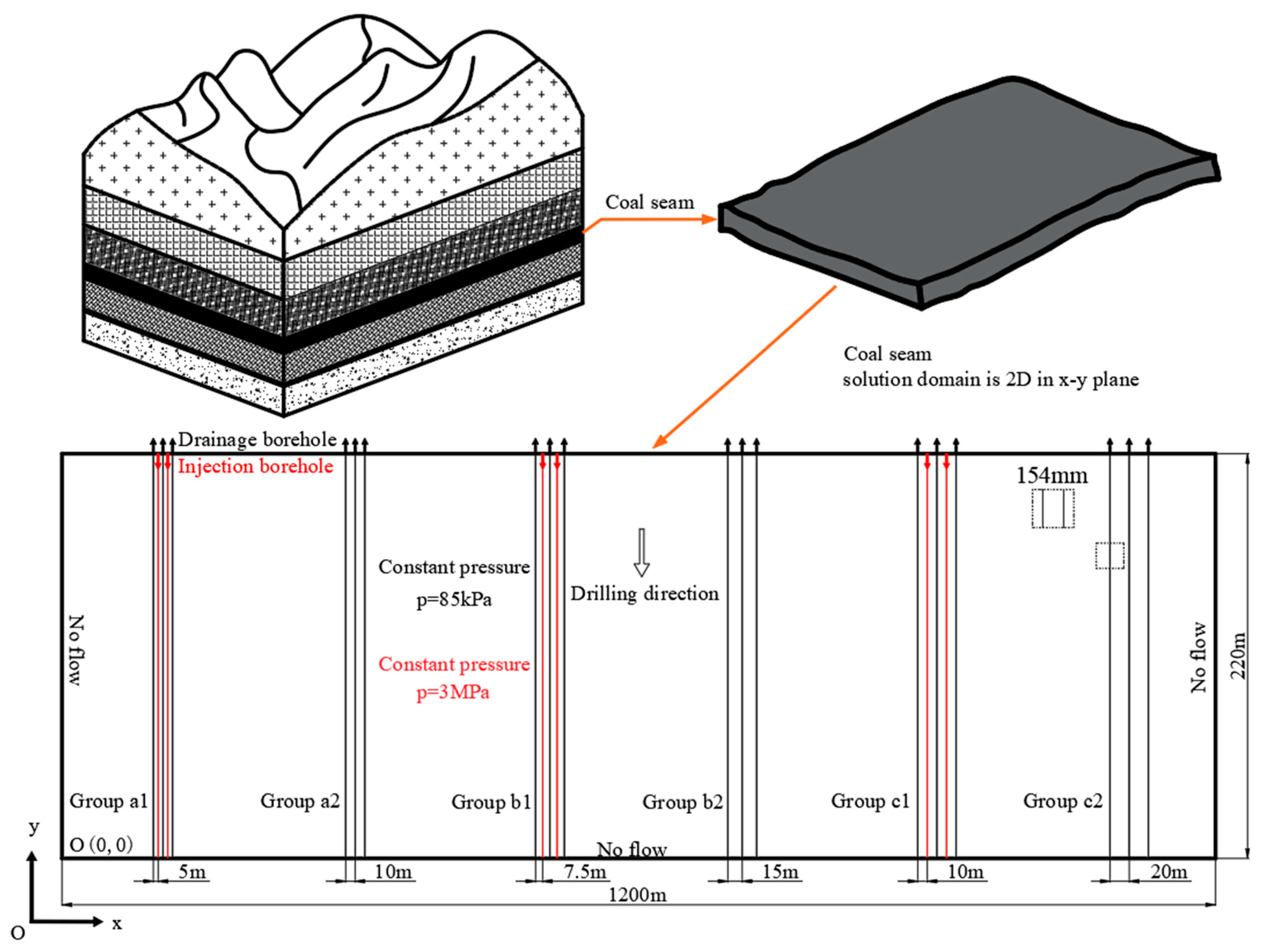
3. Finite Element Analysis of Gas Injection and Extraction Model

In this paper, a fluid solid coupling model is established to study the promoting effect of injecting high-pressure gas into coal seams on gas drainage. The studied coal mine is in Qinshui Coalfield, Shanxi Province, China. As shown in Figure 1, the burial depth of the coal seam studied in this paper is 352~482 m, the length and width of the coal seam are 220 m and 1600 m, respectively, and the average coal seam gas pressure is 1.48 MPa, which is much higher than the value specified by the Ministry of Coal Safety of the Chinese government (0.74 MPa). The initial permeability of the coal seam is 7.64 × 10⁻¹⁷ m2. Due to the low initial permeability of the coal seam, the effect of single gas drainage is not ideal, the problem of gas over the limit cannot be solved, and the gas drainage time is too long. It is proposed to inject high-pressure air into the coal seam to promote gas drainage to solve the problem of gas drainage. Based on this, the following simulations were conducted to evaluate the feasibility of high-pressure air injection to encourage drainage gas. The drilling arrangement was optimized according to the simulation results.
The simplified model of the coal seam and the borehole layout is shown in the figure. The geometric model used in the simulation is simplified from the actual coal seam gas drainage conditions, and the size is 1600 m × 220 m. The average thickness of the pre-drained coal seam is 1.83 m, which is very small compared to the length of the coal seam, so the model is simplified to a two-dimensional model [39]. Referring to the gas geological conditions of the coal seam, the equipment of the coal mine, and the experience of gas drainage in the previous working face, a series of drill holes are set up in the solved model; the length and radius of the drill holes are 220 m and 154 mm, respectively. The sealing size of the gas drainage hole is generally less than 20 m, much smaller than the length of the drainage hole. Therefore, the sealing part was not considered when building the model to avoid the negative impact of the drilled hole’s sealing position on the model’s finite element mesh. A constant pressure of 85 kPa was applied to the methane extraction borehole, and no flow conditions were applied to the remaining three boundaries of the model.
Figure 1 shows six groups of drilling holes set in the coal seam, with different drilling hole spacings, respectively. Group a1, Group b1, and Group c1 adopt the gas drainage method of high-pressure air injection, and the distances between the drainage holes and the injection holes are 5 m, 7.5 m, and 10 m, respectively. The number of drilling holes in each group is five, drainage and injection holes are alternately arranged, and the outermost are drainage holes. Group a2, group b2, and group c2 adopt the method of single gas drainage, the number of drilling holes in each group is three, and the distances between the extraction holes are 10 m, 15 m, and 20 m, respectively. The distance between each group of holes is 200 m to ensure that there will be no influence between different groups of holes. The initial permeability, gas pressure, and Young’s modulus of the coal seam were set as 7.64 × 10⁻¹⁷ m2, 1.48 MPa, and 2713 MPa, respectively [28].

4. Results and Discussion

After 100 d and 600 d of extraction, the CH4 pressure distribution in the coal seam is shown in Figure 2. The gas pressure around the borehole after 600 d of drainage is much lower than that after 100 d of drainage. When the extraction effects of groups a1 and a2 are compared, extraction group a1 has a lower overall CH4 pressure than single extraction group a2. Due to the small distance between the two groups of drilling holes, the CH4 pressure after extraction is low, and the contrast effect is not apparent. In the figure, after the CH4 force of extraction group b1 was drained for 600 d, the overall gas pressure was significantly lower than that of the single extraction group b2. Due to the larger spacing between the boreholes, the comparison effect of gas pressure distribution in extraction group c1 and the single extraction group c2 is more significant. After 600 d of drainage, the gas drainage effect of group c2 is unqualified, and the effective gas drainage area is only around the drainage hole, and the area is small. The gas pressure between drilling holes in group c1 is significantly lower than that in group c2, and the effective drainage area is much larger than that in single-drainage group c2. The high-pressure gas injection hole effectively communicates the drainage area between the two long-distance drainage holes. By setting the injection hole between the two drainage holes, the gas drainage effect is significantly improved, and the gas pressure in the coal seam is reduced considerably. The maximum gas pressure of the coal seam is 1.48 MPa, and the minimum gas pressure is 0.85 kpa of the suction negative pressure of the borehole.
Figure 3 shows the variation in the maximum gas pressure between each group of boreholes with time. The extraction group’s gas drainage standard time and gas pressure reduction rate (groups a1–c1) were significantly better than those of the single extraction group (groups a2–c2). The maximum pressure of each group of boreholes decreased with increased extraction time. The primary extraction times of Group a1, Group a2, Group b1, Group b2, and Group c1 are 110 d, 219 d, 220 d, 425 d, and 374 d, respectively. Under the same sampling interval, the sampling group’s sampling time is half that of a single sampling group. After 600 d of drainage, the Group c2 gas pressure did not meet the safety standard. The injection hole is set between the two drainage holes, and the time for Group c1 to reach the drainage standard is significantly reduced. The maximum gas pressure reduction rate decreases with time for the three feasible injection intervals. By fixing the extraction time at 600 d, the spacing of the extraction holes can be further expanded to minimize the drilling volume.
Due to the appropriate spacing between the injection holes of Group c1, the extraction effect is the best. Taking Group c1 as an example, the specific impact of injecting high-pressure air to promote gas drainage is studied. Figure 4 shows the CH4 pressure changes in extraction group c1 at different extraction times. The gas pressure distribution in the coal seam is further in the time of 100 d, 200 d, 300 d, 400 d, 500 d, and 600 d of extraction. After 100 d of drainage, only the gas pressure near the drainage hole is low, and the influence range is small. As the extraction time increases (Figure 4b–d), high-pressure air is continuously injected, and the gas pressure in the coal seam decreases significantly. In Figure 4e, the effective drainage area runs through the space between the two drainage boreholes. After 600 d drainage, the gas pressure between two drainage boreholes drops to a safe level.
Figure 5 shows the gas pressure along (y = 110, x   (1070, 1150)) as a function of the extraction time 100 d, 200 d, 300 d, 400 d, 500 d, and 600 d. The gas pressure is parabolic between the two extraction boreholes, and the parabola has different characteristics at different extraction times. The maximum gas pressure is located between the two extraction holes and decreases with the increase of gas injection time. The maximum gas pressure between the two extraction boreholes was reduced to a safe level when the extraction time was 400 d.
The N2 distribution of group C boreholes under different extraction times is shown in Figure 6, and the N2 pressure near the air injection hole increases with the continuous injection of air. After 100 d of air injection, the injected N2 diffuses to the vicinity of the extraction hole, and N2 penetrates the area between the extraction hole and the injection hole. CH4 near the injection hole is flushed to the vicinity of the extraction hole to be drained. Since the proportion of O2 in the injected air is lower than that of N2 after the same operation and gas injection time, the pressure distribution of O2 in the coal seam is similar to that of N2 after the same operation and gas injection time. The maximum value of N2 pressure is 2.37 MPa, and the full value of O2 pressure is 0.63 MPa.
Figure 7 shows the changes in N2 and O2 pressures of Group C drilling holes under different extraction times. The pressures of N2 and O2 in the coal seam are other, but some changes have the same trend. The pressure of N2 and O2 increased fastest near the gas injection hole, and the gas growth rate gradually decreased with the increase of gas injection time. In the initial gas injection stage, the gas pressure increases the most immediately. After 400 d of gas injection, the N2 pressure in the middle area of the two injection holes increased very little, and the O2 pressure hardly changed.
The drilling spacing in the above research is optimized to achieve efficient gas drainage by gas injection. The optimized drilling spacing can effectively reduce the gas stress in the coal seam, and at the same time, minimize the engineering volume of the drilling, to reduce the extraction cost. Figure 5 shows the gas pressure variation when the distance between the extraction and injection holes is 10 m. After 600 d of extraction, the gas pressure in the coal seam is much lower than the safety standard of 0.74 MPa. It can be seen from Figure 3 that the time to reach the pinnacle of extraction is 374 d, and there are still 226 d before 600 d. Based on the above research, the spacing between the extraction hole and the injection hole is set to 11.5 m, 12 m, 12.5 m, 13 m, and 13.5 m in sequence to ensure that other parameters remain unchanged. The distance of each group of drilling holes is 200 m. Name the drilling groups with different spacings as Group D, Group E, Group F, Group G, and Group H, respectively.
For different drainage intervals, the distribution of the gas pressure safe area after 600 d drainage is shown in Figure 8. The gas pressure in the coal seam is less than 0.74 MPa as a safety zone. The red in the figure is the safe area, and the blue is the area that does not meet the extraction standards. The top black arrows indicate the location of the drainage boreholes, and the red arrows indicate the location of the injection boreholes. After 600 d of extraction, the gas pressure in the area between the drilling holes of Group D, Group E, and Group F was all lower than 0.74 MPa, eliminating the danger of coal and gas outbursts. The gas pressure in some Group G and Group H areas exceeded 0.74 MPa. With the increase in the drilling distance, the size of the substandard area also increased.
Figure 9 shows the gas pressure changes at different intervals and the maximum gas pressure changes at other extraction times after 600 d of extraction. Figure 9a shows the gas pressure distribution along y = 110 m within a range of 64 m from the center of each group of intermediate drainage holes. With the increase in borehole spacing, the gas drainage effect gets worse and worse. The gas pressures in Group D, Group E, and Group F drilling areas are all lower than 0.74 MPa. In Group G, only a tiny part of the area was not up to the standard, which was x   (816.9, 821.3) and x   (842.9, 847.3), and the total length was 8.8 m. The unqualified areas of Group H are significantly larger than those of Group G, which are x   (1014, 1023) and x   (1041, 1050), with a total length of 18 m. Figure 9b shows the variation of the maximum gas pressure in the drainage area with different spacings with increased extraction time. The maximum gas pressure decreases gradually with the increase in the extraction time and falls with the increase in the drill hole spacing. After 600 d of drainage, the maximum gas pressures in Group D, Group E, Group F, and the drilling areas have reached the safety standard. To summarize, the goal is to ensure that the gas drainage effect meets the standard of safe mining while requiring the least amount of drilling engineering. The drilling spacing of Group F is selected, and the spacing between the drainage holes and the injection holes is set to 12.5 m for the best result.

5. Feasibility Analysis and Sustainability

Due to the air containing a certain amount of O2, it may cause the coal body to oxidize and heat up. Before adopting gas injection and extraction measures, it is necessary to analyze the feasibility of gas injection in combination with coal mine geological conditions. In terms of gas injection and extraction mechanism, after high-pressure air injection, the gas desorbed from the coal seam can be quickly replaced and flushed out by the injected air. The gas injection can also reduce the partial pressure of gas in the borehole and promote gas desorption. In addition, the gas injection can increase the gas pressure gradient between the gas injection hole and the extraction hole, and increase the gas seepage velocity, thereby increasing the gas extraction efficiency.
Regarding the safety and feasibility of high-pressure air injection, coal seam spontaneous combustion is a complex physical and chemical process. According to the automatic combustion tendency of coal seams, coal seams can be divided into effortlessly spontaneous combustion coal seams, spontaneous combustion coal seams, and non-spontaneous combustion coal seams. Three conditions are required for the spontaneous combustion of coal seams: the coal seam is a natural coal seam or a coal seam that is easy to combust spontaneously; there is enough oxygen in the coal seam; the coal body is oxidized, and the generated heat cannot be dissipated in a short time, and the heat continues to increase, eventually reaching the coal seam ignition point. Since the coal seam of this coal mine is not accessible to nature, the spontaneous combustion period of the coal seam is 64 d. When a large amount of air is injected into the coal seam, the coal seam contains a large amount of oxygen, and the coal will undergo a certain degree of oxidation. However, since gas injection can increase the pressure gradient between the extraction and injection holes, the gas migration speed becomes faster. The heat generated in the coal seam is quickly taken away in the process of gas migration, and it is difficult to reach the coal seam ignition point locally. Therefore, the injection of high-pressure air to promote gas extraction proposed in this paper is feasible.
Regarding item 13 of the United Nations Sustainable Development Goal: take urgent action to combat climate change and its impacts; the current production of greenhouse gases from human activities is the highest ever recorded. The greenhouse effect of CH4 is 25 times that of CO2 [2], and coal seams are rich in CH4. As the world’s largest coal producer and consumer, the question of how to effectively utilize CH4 in coal seams and minimize the emission of CH4 into the air will become the most important one to answer. The high-pressure air injection to promote gas extraction proposed in this paper can reduce the gas pressure in the coal seam on the one hand, and on the other hand, can greatly promote the recovery and utilization of the gas in the coal seam and reduce the emission of coal seam gas into the air. The most notable feature of this method is that the injected gas selects air, which minimizes the cost of gas recovery and utilization, increases the popularity of gas extraction, and greatly reduces the impact of CH4 on climate.

6. Conclusions

Aiming to address the poor effect of gas drainage in low-permeability coal seams, this paper proposes a method of promoting gas drainage by injecting high-pressure air. A fluid-solid coupling model for gas drainage promoted by high-pressure air injection is established based on the coal mine gas drainage and the actual parameters of the coal seam. The finite element method was used to solve the established model, and the diffusion and migration process of gas and injected gas during high-pressure air injection was studied. Combined with the simulation results, the distance between the injection holes in the coal mine is optimized, and the problem of underground gas exceeding the limit is solved. The specific conclusions are as follows:
  • A fluid-structure coupling model for gas drainage promoted by high-pressure air injection was established. The model improves the dynamic permeability and considers the shrinkage and expansion of the matrix caused by high-pressure air injection.
  • A series of drill holes with different extraction categories and different drill hole spacings were set up. When comparing the extraction effects of high-pressure air injection and single gas extraction, high-pressure air injection can greatly improve gas extraction efficiency. Under the same extraction interval, the time to reach the standard of extraction by gas injection extraction is half of that of single extraction.
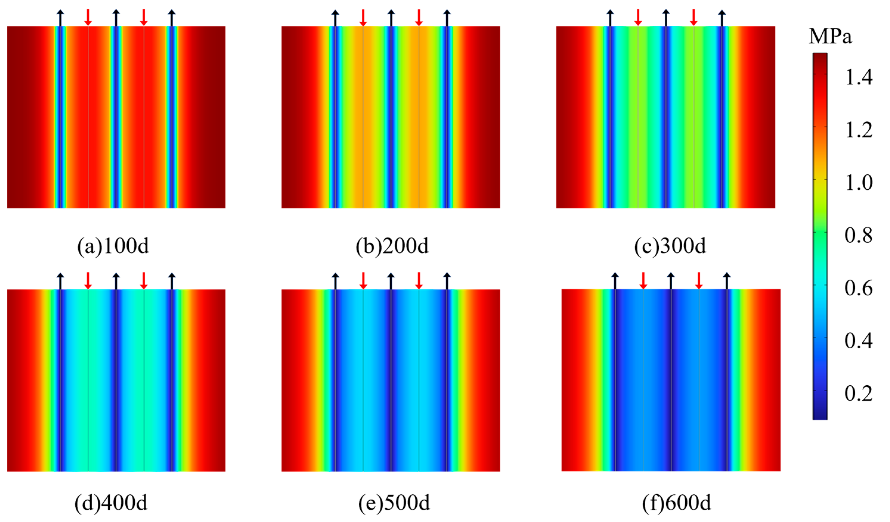
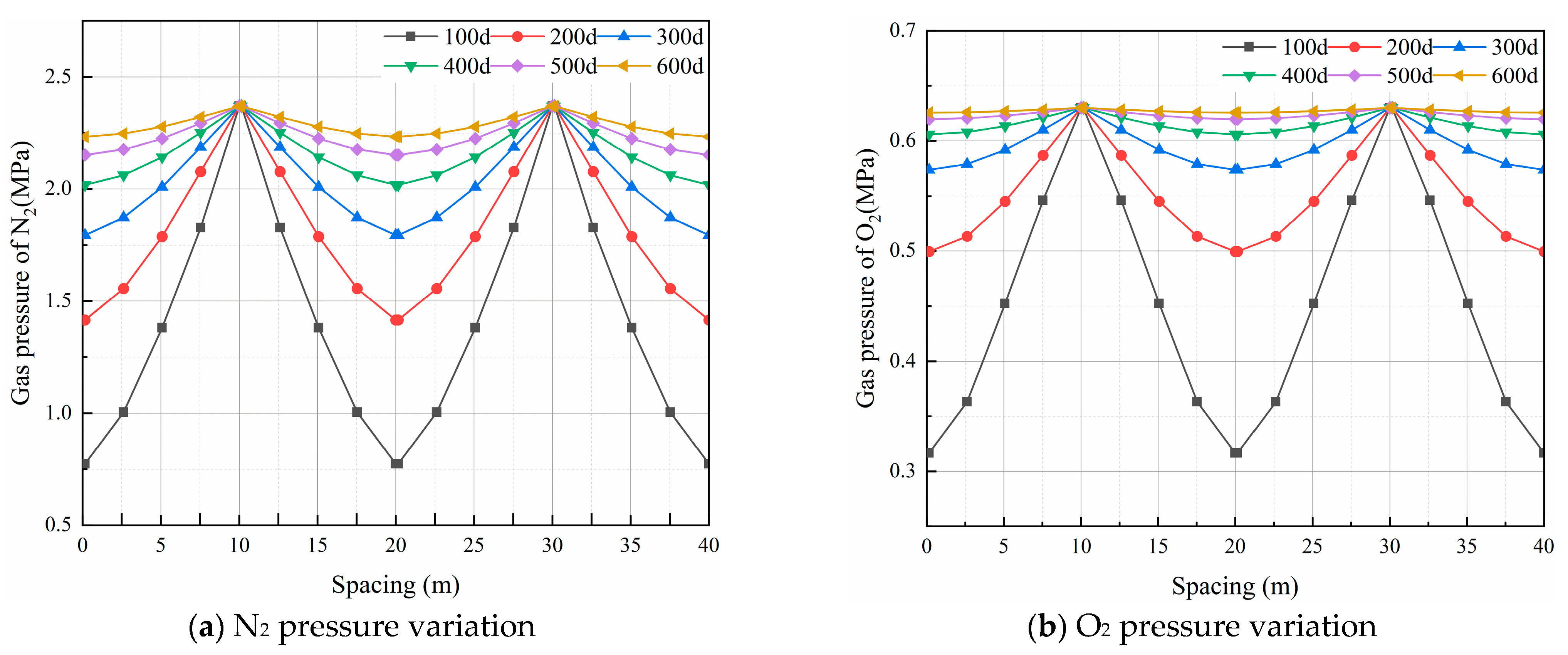
  • The pressure distribution and changes of CH4, N2, and O2 in the process of high-pressure air injection and extraction were analyzed. In the early stage of injection, only the CH4 pressure near the extraction hole and the injection hole was low, but the influence range was small; with the increase of time, the CH4 pressure between the injection holes decreased significantly, and the N2 and O2 pressure continued to increase, and finally penetrated the extraction hole and injection holes.
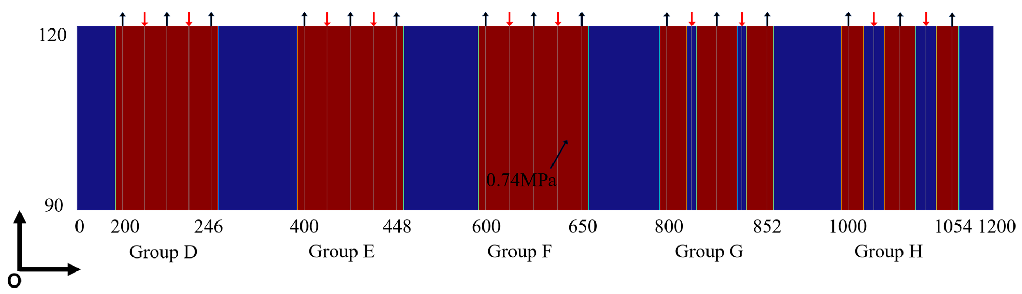
  • Combined with the simulation results, a series of simulations were carried out to optimize the drilling arrangement. Under the background of coal seam gas geological conditions and gas injection pressure of 3 MPa in this paper, to achieve the best safe extraction effect and minimum drilling volume, it is best to set the distance between the extraction hole and the injection hole to 12.5 m.
Note that the fluid-structure coupling model of high-pressure air-promoted gas drainage needs to be further improved. In this paper, according to the coal seam conditions, the effects of water fracture and adsorption heat on coal seam permeability are ignored. This paper only focuses on the promotion effect of high-pressure gas injection on coal seam gas drainage under the conditions of fixed gas injection pressure. Subsequent research will improve the fluid-structure interaction model, and combine the gas injection pressure to study the promotion effect of high-pressure air injection on gas drainage.

Author Contributions

Methodology, X.Z., W.X. and C.L.; data curation, W.X., P.L. and X.Z.; formal analysis, X.Z. and W.X.; investigation, P.L., B.L., J.W. and X.G.; project administration, X.Z.; software, C.L., B.L. and W.X.; writing—original draft preparation, B.L.; writing—review and editing, X.Z., W.X., B.L., G.L. and K.M.S.; funding acquisition, X.Z. All authors have read and agreed to the published version of the manuscript.

Funding

This research was funded by Research on Intellectual Property Bottleneck and Countermeasures of Guizhou Coal Industry under the Target of “Double Carbon” (Qianzhi Strategy [2022] 10), Guizhou “100 leading talents” and “1000 innovative and entrepreneurial talents” (Guizhou people receive and distribute [2018] 4-12), the Talent at Guizhou Ke Platform of the Academician Workstation of Liupanshui Teachers College (YSZ [2021] 001), the Postgraduate Research & Practice Innovation Program of Jiangsu Province (KYCX22_2623).

Institutional Review Board Statement

Not applicable.

Informed Consent Statement

Not applicable.

Data Availability Statement

Not applicable.

Conflicts of Interest

The authors declare no conflict of interest.

References

  1. Mu, Y.; Fan, N.; Wang, J. CBM recovery technology characterized by docking ground multi-branch horizontal wells with underground boreholes. Energy Sourc. Part A Recovery Util. Environ. Eff. 2021, 43, 645–659. [Google Scholar] [CrossRef]
  2. Fan, N.; Wang, J.; Deng, C.; Fan, Y.; Mu, Y.; Wang, T. Numerical study on enhancing coalbed methane recovery by injecting N2/CO2 mixtures and its geological significance. Energy Sci. Eng. 2020, 8, 1104–1119. [Google Scholar] [CrossRef] [Green Version]
  3. Fan, C.; Li, S.; Elsworth, D.; Han, J.; Yang, Z. Experimental investigation on dynamic strength and energy dissipation characteristics of gas outburst-prone coal. Energy Sci. Eng. 2020, 8, 1015–1028. [Google Scholar] [CrossRef]
  4. Sobczyk, J. A comparison of the influence of adsorbed gases on gas stresses leading to coal and gas outburst. Fuel 2014, 115, 288–294. [Google Scholar] [CrossRef]
  5. Yang, X.; Wang, G.; Du, F.; Jin, L.; Gong, H. N2 injection to enhance coal seam gas drainage (N2-ECGD): Insights from underground field trial investigation. Energy 2022, 239, 122247. [Google Scholar] [CrossRef]
  6. Zhou, F.; Oraby, M.; Luft, J.; Guevara, M.O.; Keogh, S.; Lai, W. Coal seam gas reservoir characterization based on high-resolution image logs from vertical and horizontal wells: A case study. Int. J. Coal Geol. 2022, 262, 104110. [Google Scholar] [CrossRef]
  7. Fan, C.; Li, S.; Luo, M.; Yang, Z.; Lan, T. Numerical simulation of hydraulic fracturing in coal seam for enhancing underground gas drainage. Energy Explor. Exploit. 2019, 37, 166–193. [Google Scholar] [CrossRef] [Green Version]
  8. Yang, Y.; Han, P.; Zhao, Z.; Chen, W. The Method of Determining Layer in Bottom Drainage Roadway Taking Account of the Influence of Drilling Angle on Gas Extraction Effect. Sustainability 2022, 14, 5449. [Google Scholar] [CrossRef]
  9. Fang, Z.; Li, X.; Wang, G.G.X. A gas mixture enhanced coalbed methane recovery technology applied to underground coal mines. J. Min. Sci. 2013, 49, 106–117. [Google Scholar] [CrossRef]
  10. Lin, J.; Ren, T.; Cheng, Y.; Nemcik, J.; Wang, G. Cyclic N2 injection for enhanced coal seam gas recovery: A laboratory study. Energy 2019, 188, 116115. [Google Scholar] [CrossRef]
  11. Kumar, H.; Elsworth, D.; Mathews, J.P.; Liu, J.; Pone, D. Effect of CO2 injection on heterogeneously permeable coalbed reservoirs. Fuel 2014, 135, 509–521. [Google Scholar] [CrossRef]
  12. Xu, C.; Wang, K.; Li, X.; Yuan, L.; Zhao, C.; Guo, H. Collaborative gas drainage technology of high and low level roadways in highly-gassy coal seam mining. Fuel 2022, 323, 124325. [Google Scholar] [CrossRef]
  13. Wu, Y.; Liu, J.; Elsworth, D.; Chen, Z.; Connell, L.; Pan, Z. Dual poroelastic response of a coal seam to CO2 injection. Int. J. Greenh. Gas Control 2010, 4, 668–678. [Google Scholar] [CrossRef]
  14. Zhou, F.; Hussain, F.; Cinar, Y. Injecting pure N2 and CO2 to coal for enhanced coalbed methane: Experimental observations and numerical simulation. Int. J. Coal Geol. 2013, 116–117, 53–62. [Google Scholar] [CrossRef]
  15. Guan, C.; Liu, S.; Li, C.; Wang, Y.; Zhao, Y. The temperature effect on the methane and CO2 adsorption capacities of Illinois coal. Fuel 2018, 211, 241–250. [Google Scholar] [CrossRef]
  16. Fang, H.; Sang, S.; Liu, S. The coupling mechanism of the thermal-hydraulic-mechanical fields in CH4-bearing coal and its application in the CO2-enhanced coalbed methane recovery. J. Pet. Sci. Eng. 2019, 181, 106177. [Google Scholar] [CrossRef]
  17. Liu, Q.; Cheng, Y.; Ren, T.; Jing, H.; Tu, Q.; Dong, J. Experimental observations of matrix swelling area propagation on permeability evolution using natural and reconstituted samples. J. Nat. Gas Sci. Eng. 2016, 34, 680–688. [Google Scholar] [CrossRef]
  18. Jiang, Z.; Quan, X.; Tian, S.; Liu, H.; Guo, Y.; Fu, X.; Yang, X. Permeability-Enhancing Technology through Liquid CO2 Fracturing and Its Application. Sustainability 2022, 14, 10438. [Google Scholar] [CrossRef]
  19. Lin, J.; Ren, T.; Wang, G.; Booth, P.; Nemcik, J. Experimental investigation of N2 injection to enhance gas drainage in CO2-rich low permeable seam. Fuel 2018, 215, 665–674. [Google Scholar] [CrossRef]
  20. Masoudian, M.S.; Airey, D.W.; El-Zein, A. The role of coal seam properties on coupled processes during CO2 sequestration: A parametric study. Greenh. Gases Sci. Technol. 2016, 6, 492–518. [Google Scholar] [CrossRef]
  21. Connell, L.D.; Sander, R.; Camilleri, M.; Heryanto, D.; Pan, Z.; Lupton, N. Nitrogen enhanced drainage of CO2 rich coal seams for mining. Int. J. Min. Sci. Technol. 2017, 27, 755–761. [Google Scholar] [CrossRef]
  22. Packham, R.; Connell, L.; Cinar, Y.; Moreby, R. Observations from an enhanced gas recovery field trial for coal mine gas management. Int. J. Coal Geol. 2012, 100, 82–92. [Google Scholar] [CrossRef]
  23. Ren, T.; Wang, G.; Cheng, Y.; Qi, Q. Model development and simulation study of the feasibility of enhancing gas drainage efficiency through nitrogen injection. Fuel 2017, 194, 406–422. [Google Scholar] [CrossRef]
  24. Zhang, L.; Wu, Y.; Pu, H.; He, X.; Li, P. The Migration of Coalbed Methane under Mining Pressure and Air Injection: A Case Study in China. Geofluids 2018, 2018, 4034296. [Google Scholar] [CrossRef]
  25. Wei, M.-Y.; Liu, J.; Liu, Y.-K.; Liu, Z.-H.; Elsworth, D. Effect of adsorption-induced matrix swelling on coal permeability evolution of micro-fracture with the real geometry. Pet. Sci. 2021, 18, 1143–1152. [Google Scholar] [CrossRef]
  26. Fan, C.; Elsworth, D.; Li, S.; Zhou, L.; Yang, Z.; Song, Y. Thermo-hydro-mechanical-chemical couplings controlling CH4 production and CO2 sequestration in enhanced coalbed methane recovery. Energy 2019, 173, 1054–1077. [Google Scholar] [CrossRef]
  27. Zhao, Y.; Lin, B.; Liu, T.; Zheng, Y.; Kong, J.; Li, Q.; Song, H. Flow field evolution during gas depletion considering creep deformation. J. Nat. Gas Sci. Eng. 2019, 65, 45–55. [Google Scholar] [CrossRef]
  28. Gao, H. Simulation and optimization of high-pressure air injection promoting underground coal seam gas drainage. Energy Sources Part A Recovery Util. Environ. Eff. 2020, 1–17. [Google Scholar] [CrossRef]
  29. Song, H.; Lin, B.; Zhong, Z.; Liu, T. Dynamic Evolution of Gas Flow during Coalbed Methane Recovery to Reduce Greenhouse Gas Emission: A Case Study. ACS Omega 2022, 7, 29211–29222. [Google Scholar] [CrossRef]
  30. Liu, Q.; Cheng, Y.; Wang, H.; Zhou, H.; Liang, W.; Wei, L.; Liu, H. Numerical assessment of the effect of equilibration time on coal permeability evolution characteristics. Fuel 2015, 140, 81–89. [Google Scholar] [CrossRef]
  31. Liu, Q.; Chu, P.; Zhu, J.; Cheng, Y.; Wang, D.; Lu, Y.; Liu, Y.; Xia, L.; Wang, L. Numerical assessment of the critical factors in determining coal seam permeability based on the field data. J. Nat. Gas Sci. Eng. 2020, 74, 103098. [Google Scholar] [CrossRef]
  32. Zhu, W.C.; Wei, C.H.; Liu, J.; Qu, H.Y.; Elsworth, D. A model of coal–gas interaction under variable temperatures. Int. J. Coal Geol. 2011, 86, 213–221. [Google Scholar] [CrossRef]
  33. Majid Hassanizadeh, S. Derivation of basic equations of mass transport in porous media, Part 2. Generalized Darcy’s and Fick’s laws. Adv. Water Resour. 1986, 9, 207–222. [Google Scholar] [CrossRef]
  34. Lim, K.T.; Aziz, K. Matrix-fracture transfer shape factors for dual-porosity simulators. J. Pet. Sci. Eng. 1995, 13, 169–178. [Google Scholar] [CrossRef]
  35. Mora, C.A.; Wattenbarger, R.A. Analysis and Verification of Dual Porosity and CBM Shape Factors. J. Can. Pet. Technol. 2009, 48, 17–21. [Google Scholar] [CrossRef]
  36. Wang, K.; Wang, L.; Ju, Y.; Dong, H.; Zhao, W.; Du, C.; Guo, Y.; Lou, Z.; Gao, H. Numerical study on the mechanism of air leakage in drainage boreholes: A fully coupled gas-air flow model considering elastic-plastic deformation of coal and its validation. Process Saf. Environ. Prot. 2022, 158, 134–145. [Google Scholar] [CrossRef]
  37. Mian, C.; Zhida, C. Effective stress laws for multi-porosity media. Appl. Math. Mech. 1999, 20, 1207–1213. [Google Scholar] [CrossRef]
  38. Zhang, J.; Roegiers, J.-C.; Bai, M. Dual-porosity elastoplastic analyses of non-isothermal one-dimensional consolidation. Geotech. Geol. Eng. 2004, 22, 589–610. [Google Scholar] [CrossRef]
  39. Liu, Q.; Cheng, Y.; Wang, H.; Kong, S.; Dong, J.; Chen, M.; Zhang, H. Numerical assessment of the influences of coal permeability and gas pressure inhomogeneous distributions on gas drainage optimization. J. Nat. Gas Sci. Eng. 2017, 45, 797–811. [Google Scholar] [CrossRef]
  40. Wu, Y.; Liu, J.; Chen, Z.; Elsworth, D.; Pone, D. A dual poroelastic model for CO2-enhanced coalbed methane recovery. Int. J. Coal Geol. 2011, 86, 177–189. [Google Scholar] [CrossRef]
  41. Liu, T.; Lin, B.; Yang, W.; Liu, T.; Kong, J.; Huang, Z.; Wang, R.; Zhao, Y. Dynamic diffusion-based multifield coupling model for gas drainage. J. Nat. Gas Sci. Eng. 2017, 44, 233–249. [Google Scholar] [CrossRef]
  42. Lin, J.; Ren, T.; Wang, G.; Nemcik, J. Simulation investigation of N2-injection enhanced gas drainage: Model development and identification of critical parameters. J. Nat. Gas Sci. Eng. 2018, 55, 30–41. [Google Scholar] [CrossRef]
  43. Huo, B.; Jing, X.; Fan, C.; Han, Y. Numerical investigation of flue gas injection enhanced underground coal seam gas drainage. Energy Sci. Eng. 2019, 7, 3204–3219. [Google Scholar] [CrossRef]
Figure 1. Geometry and boundary conditions of coal seam gas injection (Red represents injection borehole).
Sustainability 14 13699 g001
Figure 2. Gas pressure distribution after 100 d and 600 d of extraction.
Sustainability 14 13699 g002
Figure 3. Variation in maximum gas pressure among groups of boreholes at different extraction times.
Sustainability 14 13699 g003
Figure 4. CH4 pressure distribution in group C boreholes under different extraction times; (a) 100 d (b) 200 d (c) 300 d (d) 400 d (e) 500 d (f) 600 d.
Sustainability 14 13699 g004
Figure 5. Gas pressure change of Group C.
Sustainability 14 13699 g005
Figure 6. Distribution of N2 pressure in group C boreholes under different extraction times; (a) 100 d (b) 200 d (c) 300 d (d) 400 d (e) 500 d (f) 600 d.
Sustainability 14 13699 g006
Figure 7. N2 and O2 pressure variation in group C boreholes under different extraction times. (a) N2 pressure variation (b) O2 pressure variation.
Sustainability 14 13699 g007
Figure 8. Share safe areas for gas drainage at different intervals after 600 d of drainage.
Sustainability 14 13699 g008
Figure 9. Different spacing changes in gas pressure. (a) CH4 pressure changes (b) maximum CH4 pressure changes.
Sustainability 14 13699 g009
Table 1. Critical parameters of the model.
ParameterNumerical ValueUnitAccessMark
Initial matrix porosity0.042 Field data
Initial fracture porosity0.008 Field data
Initial fracture permeability7.64 × 10−17m2Field data
Elastic modulus of coal matrix8469MPaReferenceFan et al., 2020 [2]
Poisson’s ratio0.32 Experiment
Diffusion coefficient5.48 × 10−12m2/sReferenceLiu et al., 2017 [41]
Initial CH4 pressure1.48MPaField data
Initial N2 pressure84kPaEstimate
Initial O2 pressure26kPaEstimate
Adsorption time of CH44.8day(d)Experiment
Adsorption time of N23.7day(d)Experiment
Adsorption time of O23.2day(d)Experiment
Dynamic viscosity of CH41.03 × 10−5Pa·sReferenceWu et al., 2010 [13]
Dynamic viscosity of N21.37 × 10−5Pa·sReferenceLin et al., 2019 [10]
Dynamic viscosity of O22.21 × 10−5Pa·sReferenceLin et al., 2019 [10]
Langmuir pressure constant of CH41.32MPaExperiment
Langmuir pressure constant of N21.51MPaExperiment
Langmuir pressure constant of O22.42MPaExperiment
Langmuir volume constant of CH40.0214m3/kgExperiment
Langmuir volume constant of N20.0204m3/kgExperiment
Langmuir volume constant of O20.0151m3/kgExperiment
Langmuir strain constant of CH40.0128 ReferenceLin et al., 2017 [42]
Langmuir strain constant of N20.0052 ReferenceLin et al., 2017 [42]
Langmuir strain constant of O20.0038 ReferenceHuo et al., 2017 [43]
Publisher’s Note: MDPI stays neutral with regard to jurisdictional claims in published maps and institutional affiliations.

