

Effects of Aeolian Sand and Water−Cement Ratio on Performance of a Novel Mine Backfill Material
by
 ,
,
Guodong Li
1,2,
Hongzhi Wang
1,2,*,
Zhaoxuan Liu
1,
Honglin Liu
1,2,*,
Haitian Yan
1 and
Zenwei Liu
1 1
College of Geology and Mining Engineering, Xinjiang University, Urumqi 830046, China
2
Key Laboratory of Environmental Protection Mining for Mineral Resources at Universities of Education Department of Xinjiang Uygur Autonomous Region, Xinjiang University, Urumqi 830046, China
*
Authors to whom correspondence should be addressed.
Sustainability 2023, 15(1), 569; https://doi.org/10.3390/su15010569
Submission received: 3 November 2022
/
Revised: 16 December 2022
/
Accepted: 25 December 2022
/
Published: 29 December 2022
(This article belongs to the Topic Mining Safety and Sustainability)
Abstract
:The gob-side entry retaining (GER) technique, as the family member of the pillarless coal mining system, is becoming popular, mainly attributed to its high resource recovery rate and significant environmental benefits. Seeking cost-effective backfill material to develop the roadside backfilling body (RBB) is generally a hot topic for coal operators and scholars. Except for its relatively high cost, the other shortcoming of the widely used high-water backfill material is also obvious when used in arid, semi-arid deserts or Gobi mining areas lacking water. The modified high-water backfill material (MBM) mixed with aeolian sand was recently developed as an alternative to conventional backfill materials. Some critical parameters affecting both the physical and mechanical properties of the MBM, including the amount of the aeolian sand and water-to-powder ratio of the high water-content material, have been experimentally investigated in the present research. Test results showed that the MBM featured high early strength and bearing capability after a large post-peak deformation. In particular, the adjustable setting time of the MBM through changing the amount of sand widens its application in practice. Unlike the high-water backfill material, the MBM is a typical elastoplastic material; the stress-strain curves consist of pore compression, elastic deformation, yielding, and total failure. Note that both the peak and residual strength of the MBM increased as the doping amount of aeolian sand increased, which is probably because of the impacted aeolian sand and the uniform reticular structure of the ettringite in the MBM. Compared with the high-water backfill material, only limited cementitious material and water resources are requested to cast the RBB, which provides more economical and environmental benefits for the application of the GER technique in the arid, semi-arid deserts or the Gobi mining areas.
1. Introduction
Concern about many serious eco-environmental problems caused by coal exploitation is a global problem [1,2]. As a result, much research in recent years has focused on the development of mining techniques that are environmentally friendly [3]. Under the rapid development of the mining industry in recent decades, the continuous and irreparable impacts of contaminated air, degraded soil, polluted water, damaged biodiversity, and geological disaster of mining operations may increase the risks of mine development [4]. The coal reserves in Northwestern China account for about 70% of China’s total coal resources [5,6]. However, most coal mines are distributed among these arid and semi-arid regions, where water resources are in short supply, and there is sparse vegetation, a barren ground surface, and ecological vulnerability [7]. As is well-known, aridity and water shortage are the major natural disasters in Northwestern China and the primary causes of ecological vulnerability in this region [8,9]. In recent years, however, large-scale coal mining activities in Western China have further aggravated ecological deterioration [10]. Environmental problems caused by general mining processes mainly included: (1) the influence on people, biota, biodiversity, the atmospheric environment, and surface ecosystems [11,12,13]; (2) the influence on the soil environment [14], the hydrological system [15], and severe geological disasters. These effects were combined with each other and caused more complicated consequences [11]. Therefore, maximally adapting the coal mining activities to the local ecological environment was an inevitable road towards “green coal mine construction and green mining in Western China”.
Much research in recent years has been widely applied to control eco-environmental problems caused by coal exploitation, such as grout injection [16], room mining [17], strip mining [18], backfill mining [19], and pillarless coal mining [20]. The increased favor for the backfill mining method was due to several advantages: high extraction rate, effective control of ground pressure, reduction of ground surface subsidence, and eco-environment improvement of the mining region [21,22]. The backfill mining methods were divided into several types based on the backfill material used, such as hydraulic backfilling, gangue backfilling, and cemented past backfilling [23]. These backfilling methods offered viable pathways to liberate coal resources under the buildings. However, some drawbacks still existed, such as a complex backfilling process, slow backfilling speed, high backfilling cost, and unavailability of backfill materials. Recently, some new backfill materials have been developed, such as flexible formwork concrete, high-water backfill material, and cement mortar. Such novel backfill materials somehow reduce the backfilling cost and expand the application scope of the backfilling technology [24,25,26,27,28], such as roadway backfill mining [3] and pillarless coal mining [20].
The gob-side entry retaining (GER) technique enables pillarless coal mining by using a roadside backfilling body (RBB), which can effectively reduce the roadway-driven ratio, improve the resource recovery rate, and has significant economic and environmental benefits (Figure 1) [25,27]. Flexible formwork concrete and cement mortar have higher strengths but lower vertical deformation capacity. Therefore, such backfill materials hardly meet the requirement for a large deformation capacity of RBB for GER. On the other hand, high-water backfill materials have the benefits of having high early strength, high flowability of single slurry, fast setting of mixed slurry, and high bearing capability after a large post-peak deformation. Besides, such backfill materials were incompressible under triaxial compression and better adapted to the underground goaf environment, which was usually cold, damp, and enclosed [29]. Given the above discussion, high-water backfill materials are believed to be ideal for the RBB.
However, high-water backfill materials have the following defects if used in mining regions in arid and semi-arid deserts or Gobi mining regions: (1) it consumes a large amount of water to prepare high-water backfill materials, which aggravates water shortage [30]; (2) despite the high content of water, the high-water backfill material is necessary in large quantities [31]; (3) due to the low strength of the backfill body, doping massive cementitious materials enhances the strength [32]. As is well known, aeolian sand extensively occurs on the ground surface in Northwestern China. Therefore, it is easily found in nature, is inert and harmless, and causes no pollution to water bodies and the surrounding environment. Moreover, aeolian sand provides a sufficient raw material source to prepare backfill materials for coal mines [33]. Therefore, it is necessary to study an alternative to conventional backfill materials with aeolian sand, which not only liberates coal resources but also limits high-water backfill materials and water resources in the arid, semi-arid deserts or Gobi mining areas.
In the present study, we developed a modified high-water backfill material (MBM) that met the coal exploitation requirements of coal mining in Northwestern China. In the proposed novel MBM, aeolian sand was the primary aggregate and a high-water backfill material was the calcium sulphoaluminate (CSA) based cementitious grout material. Some research has been conducted in past years to understand better the physical and mechanical characteristics of backfill material and their influencing factors, which showed that the physical and mechanical properties were affected by external and internal (e.g., binder type, content, water chemical properties and content, composition, and content of aggregate) factors. Although the influence of these variables has been extensively documented in the literature, the reported results were inconsistent due to large differences in the physical, chemical, and mineralogical properties of cementitious materials and aggregates [23,34,35,36,37,38,39,40,41]. In this study, in order to expand the application scope of the MBM in coal mines located in the arid and semi-arid deserts or Gobi region, we prepared 16 test samples with a diameter of 50 mm and a height of 100 mm. Then we studied the effect of the doping amount of aeolian sand and water−cement ratio on the physical and mechanical characteristics of MBM (e.g., initial setting time, unconfined compressive strength, and its microstructure). The main outcomes of this research may contribute to the safe and green exploitation of underground coal mines in the arid and semi-arid deserts or Gobi.
2. Experimental Scheme
2.1. Test Sample Design
The sample preparation and testing were conducted at Xinjiang University. Firstly, we prepared 16 test samples with a diameter of 50 mm and a height of 100 mm. Next, the water−cement ratio and the doping amount of aeolian sand were changed as the main parameters to discuss the influence of doping aeolian sand on the mechanical properties of the MBM. Then, the samples constituted three series and ten groups. In each group, there were two nominally identical samples.
As shown in Table 1, series 1 consisted of six standard short cylinders with three different water−cement ratios (1.0, 1.5, and 2.0) and the doping amount of aeolian sand being 0%. Samples in series 2 were differentiated from each other by the cementitious grout material’s water-cement ratio (1.0, 1.5, and 2.0). The doping amount of aeolian sand was 60% in each sample. To study the influence of the doping amount of aeolian sand, we prepared eight test samples for series 3, each having a water−cement ratio of 1.0, but 4 different doping amounts of aeolian sand (0%, 20%, 40%, and 60%).
We named each test sample following a specific convention. The first number represented the water−cement ratio of the cementitious grout material, the second the doping amount of aeolian sand, and the last was a Roman numeral that differentiated two nominally identical samples. Take U-1.5-00-II as an example. U-1.5-00-II represented the second test sample, with a water−cement ratio of 1.5 in the cementitious grout slurry and the doping amount of aeolian sand being 0%.
2.2. Raw Materials
The CSA cementitious grout material was provided by Yangzhou Zhongkuang Construction New Material Technology Co., Ltd. (Yangzhou City, China). The high-water backfill material was composed of two main ingredients, A and B. It mainly consisted of sulfate aluminum cement, a suspending agent, and a set retarder. B was a mixture of lime, gypsum, a suspending agent, and an early strengthener [42]. The initial setting time was short after combining slurries A and B. Besides, the test sample developed sufficient strength within a short period. Therefore, such materials have the benefits of not causing pipeline blockage and have easy pumpability, high early strength, and environmental friendliness, with extensive application in mine backfilling, leak stoppage, and fire retardancy. The aeolian sand used for experiments came from the Kumtag Desert, one of the main deserts of northwestern China. We conducted grain size distribution on aeolian sand according to ASTMC136/C136M [43]. The cumulative grain size distribution curve (Figure 2) shows that the aeolian sand grain distributions were mainly between 0.075 mm and 0.25 mm. These grain sizes accounted for about 90% of the total mass, while the remaining were 0.25 to 1.0 mm.
2.3. Test Sample Preparation
Next, we prepared the MBM samples (Figure 3). Material slurry A had aeolian sand mixed at a specific ratio. Material B slurry had added water adequately mixed. Finally, slurry A was doped with aeolian sand combined with the slurry B doped with aeolian sand, mixed for 5 min, and was left to stand still. The mixed slurry was poured into a mold and cured for 24 h before demolding. The test sample was covered with a preservative film and placed in an enclosed container. The subsequent tests began after 7 d of maintenance.
2.4. Testing Equipment and Instruments
Our main discussions were on the influence of doping aeolian sand and the water−cement ratio on the physical and mechanical characteristics (e.g., initial setting time, unconfined compressive strength, and microstructure). The setting time of MBM should meet the requirements for the filling process for GER. If the setting time is too short, pipeline obstruction quickly happens, which will not be conducive to material transport. If the setting time is too long, MBM might not be easily formed in the goaf, thus failing to achieve the backfilling purpose. Therefore, the control of the setting time is of high importance. The Standard Vicat needle test for all test samples was as per GB/T1346-2001 [44]. We took the average initial setting time from two repeat tests on the same sample. When used to backfill the space underground, MBM was usually squeezed between the roof and floor of the coal seam. Therefore, the backfill body was subjected to uniaxial loading. The uniaxial compression test was crucial for the backfill material. We conducted the classical loading tests on MBM using the WAW-600D Hydraulic Universal Testing Machine. As shown in Figure 4, four strain gauges (SGs) were installed at the mid-height of each sample to measure axial and circumferential strains and the overall axial deformations of the samples. According to ASTMD7012-2010 [45], we used a loading rate of 1.5 mm/min for the compression test in all samples under the displacement loading mode. In order to understand the microscopic characteristics, we observed the morphology of MBM using the ZEISS LEO-1430 VP scanning electron microscope (Carl Zeiss AG, Jena, Germany).
3. Experimental Results and Discussion
3.1. Results of Vicat Needle Test
The standard Vicat needle test results are shown in Figure 5. As shown in Figure 5, doping aeolian sand would affect the initial setting time of MBM. With the doping amount of aeolian sand fixed at 60%, the initial setting times of the samples with the water−cement ratio being 1.0, 1.5, and 2.0 were shortened by 50%, 26%, and 30%, respectively, compared with those not doped with aeolian sand. When the water−cement ratio was fixed at 1.0, the initial setting time of the samples was 43 min, 53 min, 33 min, and 21 min when the doping amount of aeolian sand was 0%, 20%, 40%, and 60%, respectively. It is noteworthy that the initial setting time of the MBM decreased with the increased doping amount of aeolian sand and decreased with the water−cement ratio. It is logical that adjustment of the initial setting time by changing the doping amount of aeolian sand met the technical requirements of the construction of RBB.
3.2. Failure Modes
The failure modes from the various tests of MBM are in Figure 6. As shown in the figure (Figure 6a,c), for the pure high-water materials (e.g., U-1.0-00, U-1.5-00 and U-2.0-00) and at a small doping amount of aeolian sand (e.g., U-1.0-20), failure first occurred at one end of the sample. Then, the cracks gradually propagated from the middle to the other end of the sample. Thus, a sharp tensile crack was formed, causing the failure of the entire sample. As the doping amount of aeolian sand continued to increase (Figure 6b,c), the sample underwent axial compression and radial expansion due to pressure from above. The friction at the end of the testing machine resulted in a three-way stress zone in an inverted cone shape at the top of the testing machine, where an X-shaped crack zone developed. With sustained axial pressure, a shear fissure intersecting with the axial line appeared in the lower part of the X-shaped crack zone. This fissure became a macroscopic crack, further leading to the sample’s shear failure. Interestingly, as the doping amount of aeolian sand increased, the modified samples gradually transitioned from tensile failure to X-shaped shear failure. It seems likely that the failure modes of MBM can be affected by sand content.
3.3. Stress-Strain Curves
Using the WAW-600D Hydraulic Universal Testing Machine, we obtained the stress-strain curves of every sample. Figure 7 shows the axial stress−axial strain curves of MBM. Note that MBM is classic elastoplastic. Such material was not only compressible to adapt to surrounding rock deformation but also had residual strength even after failure. These two features are highly desirable for the construction of RBB [46].
As shown in Figure 7c–e, the doping of aeolian sand dramatically altered the characteristics of the stress−strain curve of MBM. The stress−strain curve was divisible into four stages: pore compression, elastic deformation, yield, and failure. But compared with pure high-water materials (e.g., U-1.0-00, U-1.5-00 and U-2.0-00), MBM specimens display distinctive features at these four stages.
- (1)
- Pore compression stage: This stage was more clearly distinct in the pure high-water materials (e.g., U-1.0-00, U-1.5-00, and U-2.0-00); as the water−cement ratio increased, the stage of pore compression became even more distinct (Figure 7a,b). But for MBM specimens, the scene became less precise as the doping amount of aeolian sand increased (Figure 7c). It would appear that the specimens with a larger water−cement ratio had a more remarkable pore compression stage. At the same time, the higher sand content that led to this stage was not significant. It may be because the doped aeolian sand particles filled the pores between the originally pure high-water material, reducing the number and space of pores.
- (2)
- Elastic deformation stage: This stage became less distinct and had a shorter duration for pure high-water materials (Figure 7a) and a low doping amount of aeolian sand (Figure 7c). However, as the water−cement ratio increased, this stage became less precise and had a shorter period (Figure 7a,b). In addition, as the doping amount of aeolian sand increased (Figure 7c–e), this stage became more distinct and had a longer duration. This phenomenon mainly dominated in the modified material samples U-1.0-60. It may be assumed that the more considerable amount of aeolian sand doped into the high-water material, the smaller the pores between aggregate particles. The friction between the aggregate particles could further increase due to the cementing effect of the high-water materials. Therefore, the inter-particle dislocation was more unlikely to happen.
- (3)
- Yield stage: An apparent fracture plane appeared in the samples at this stage, and the fracture propagated constantly. At a higher doping amount of aeolian sand (Figure 7b–e), the failure occurred rapidly, resulting in a higher peak and more significant compressive strength on the curve at this stage. However, for pure high-water materials and samples doped with a small amount of aeolian sand (Figure 7a,c), the peak and the compressive strength were smaller on the curve. The above might be because the friction between the aggregate particles was lower due to the larger pores between them.
- (4)
- Failure stage: The MBM displayed significantly different features at this stage. The stress−strain curve showed a more gentle decreasing trend in the pure high-water materials (Figure 7c–e). However, the stress was still high even at the maximum strain, indicating a high residual strength (Figure 7a). Apparently, the decrease was steeper on the stress−strain curve for the MBM (Figure 7b–e). The stress corresponding to the maximum strain was lower in MBM than in pure high-water materials. Besides, this stress decreased as the doping amount of aeolian sand increased (Figure 7c). It would seem that although the post-peak strength decreased slightly, the MBM had high bearing capability after a large post-peak deformation.
3.4. Consumption of Raw Materials
Figure 8 shows the compressive strengths and material consumption for different test samples. As shown in Figure 8a, the strength of the samples negatively correlated with the water−cement ratio when the doping amount of aeolian sand was 0% and 60%. When the doping amount of aeolian sand was above 40%, the strength of the sample positively correlated with the doping amount of aeolian sand, compared with the pure high-water material (e.g., U-1.0-00). Besides, the amounts of cementitious material and water negatively correlated with the doping amount of aeolian sand (Figure 8b). Compared with the pure high-water materials (e.g., U-1.0-00, U-1.5-00, and U-2.0-00), the samples with the water-cement ratio being 1.0, 1.5, and 2.0 and the doping amount of aeolian sand being 60% had an increase in strength of 45%, 83%, and 111% (Figure 8a), respectively; the amounts of cementitious material and water consumed decreased by 60% in all these doped samples. As shown above, the aeolian sand-modified high-water backfill materials had higher compressive strength. Besides, it consumed smaller amounts of cementitious materials and water in preparing these materials. It should be possible, therefore, to reduce cementitious material and water resources requested to cast the RBB, which provided new insight for the application of the GER technique in the arid and semi-arid deserts or Gobi mining areas.
4. Micromorphological Analysis
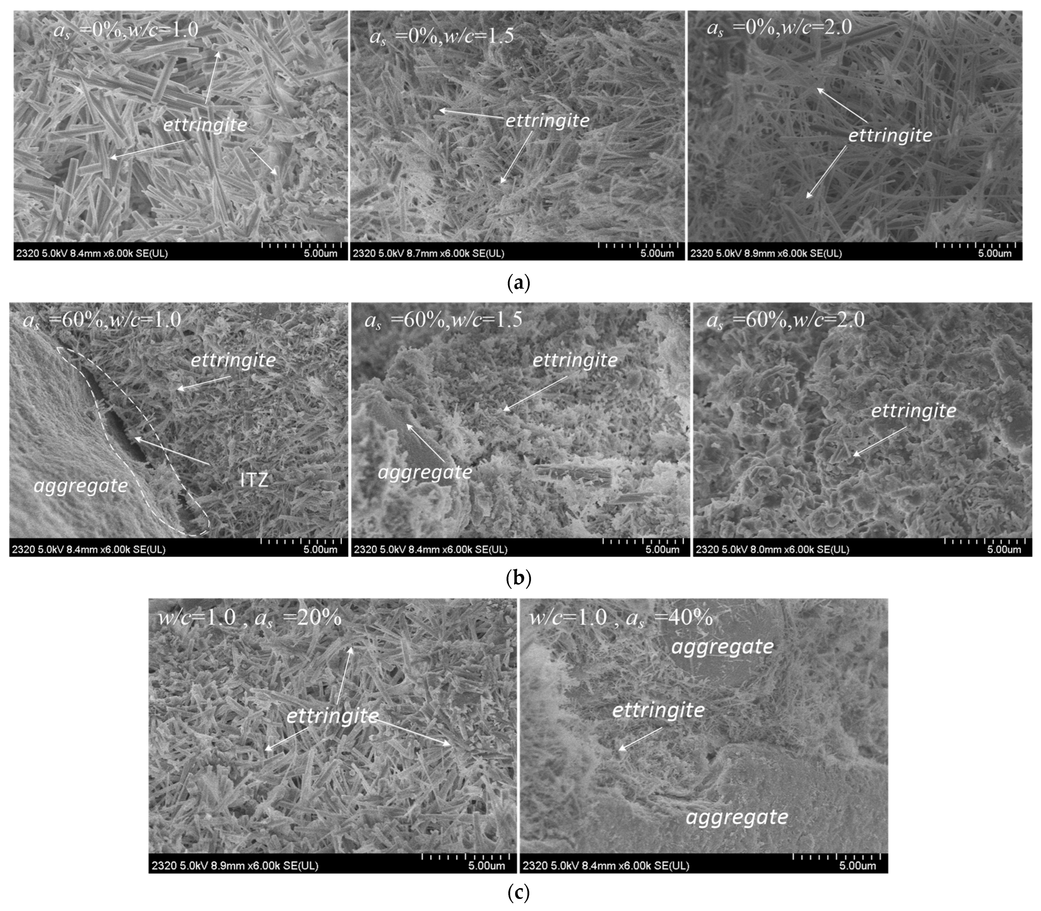
In order to understand the microscopic characteristics, we observed the morphology of MBM using the ZEISS LEO-1430 VP scanning electron microscope (SEM). Figure 9 shows 6000× SEM images of MBM. As shown in Figure 9, when the doping amount of aeolian sand was small (Figure 9a,c), the sample particles were slender and elongated, with a fibrous reticular structure. The fibrous substances were interwoven and overlapped with each other. Moreover, tight connections resulted, though some small cavities still existed. When the doping amount of aeolian sand was 20% (Figure 9c), the sample particles were short and prismatic. This may be the reason for the lower strength of the sample (e.g., U-1.0-20) compared to the pure high-water material (e.g., U-1.0-00). As shown in Figure 9b,c, when the doping amount of aeolian sand increased, the sample particles had a denser fibrous reticulate structure. This was unlikely to form large penetrating cavities. By contrast, the structure with the lower doping amount of aeolian sand was loose and more likely to have large penetrating cavities. Therefore, it seems plausible that the materials with the denser fibrous reticulate structure were stronger than those with the loose structure.
5. Conclusions
In this study, we introduced a modified high-water backfill material (MBM) mixed with aeolian sand. To fully understand both physical and mechanical properties of the MBM, a total of 16 samples with a diameter of 50 mm and a height of 100 mm were experimentally tested. Some critical parameters, such as the doping amount of aeolian sand and the water−cement ratio, have been well concerned. The initial setting time, unconfined compressive strength as well as the microstructure of the MBM were investigated in-depth. The main conclusions based on the results and discussions are listed below:
- (1)
- The initial setting time of the MBM decreased with the increased doping amount of aeolian sand and decreased with the water−cement ratio of the high water backfill material. It is thus possible to regulate the setting time of the MBM by changing the doping amount of aeolian sand to meet the technical requirements of the construction of RBB.
- (2)
- The typical stress−strain curve of the MBM consists of four portions: pore compression, elastic deformation, yield, and failure, indicating that the MBM is a typical elastoplastic material.
- (3)
- The MBM consistent with the high-water backfill material has the benefits of having high early strength, high flowability of single slurry, fast setting of mixed slurry, and high bearing capability after a large post-peak deformation.
- (4)
- Both the peak and the residual strength of the MBM increased with the doping amount of aeolian sand within a specific scope, which may be because the existence of the aeolian sand impacted the integrity and uniformity of the reticular structure of ettringite in the MBM.
- (5)
- Compared with the high-water backfill material, only limited cementitious material and water resources are requested to cast the RBB, which provides new insight for the application of the GER technique in arid, semi-arid deserts or Gobi mining areas.
Author Contributions
Conceptualization, G.L., H.W. and H.L.; methodology, G.L. and Z.L. (Zhaoxuan Liu); validation, G.L., H.W. and H.L.; investigation, G.L.; data curation, G.L., Z.L. (Zhaoxuan Liu), H.Y. and Z.L. (Zenwei Liu); writing—original draft, G.L., H.W., Z.L. (Zhaoxuan Liu), H.L., H.Y. and Z.L. (Zenwei Liu); funding acquisition, H.W. and H.L.; project administration, G.L., H.W. and H.L.; writing—review and editing, H.W. and H.L. All authors have read and agreed to the published version of the manuscript.
Funding
This research was funded by the Key Project of Joint Funds of the National Natural Science Foundation of China (U1903209), the Natural Science Foundation of Xinjiang Uyghur Autonomous Region (2022D01E31), the National College Student Innovation Project (202110755008), the Natural Science Foundation of Xinjiang Uyghur Autonomous Region (2022D01A116) and the National Natural Science Foundation (51964043).
Institutional Review Board Statement
Not Applicable.
Informed Consent Statement
Not Applicable.
Data Availability Statement
Not Applicable.
Acknowledgments
The authors are grateful for the technical support and donations provided by Yangzhou Zhongkuang Construction New Material Technology Co., Ltd. (Yangzhou City, China).
Conflicts of Interest
The authors declare no conflict of interest.
References
- Bai, E.; Guo, W.; Tan, Y. Negative externalities of high-intensity mining and disaster prevention technology in China. Bull. Eng. Geol. Environ. 2019, 78, 5219–5235. [Google Scholar] [CrossRef]
- Xu, Y.; Shen, S.; Cai, Z.; Zhou, G. The state of land subsidence and prediction approaches due to groundwater withdrawal in China. Nat. Hazards 2008, 45, 123–135. [Google Scholar] [CrossRef]
- Bai, E.; Guo, W.; Tan, Y.; Huang, G.; Guo, M.; Ma, Z. Roadway Backfill Mining with Super-High-Water Material to Protect Surface Buildings: A Case Study. Appl. Sci. 2019, 10, 107. [Google Scholar] [CrossRef] [Green Version]
- Dong, L.; Shu, W.; Li, X.; Zhang, J. Quantitative evaluation and case studies of cleaner mining with multiple indexes considering uncertainty factors for phosphorus mines. J. Clean. Prod. 2018, 183, 319–334. [Google Scholar] [CrossRef]
- Dong, S.; Wang, H.; Guo, X.; Zhou, Z. Characteristics of Water Hazards in China’s Coal Mines: A Review. Mine Water Environ. 2021, 40, 325–333. [Google Scholar] [CrossRef]
- Wen, Q.; Li, J.; Mwenda, K.M.; Ervin, D.; Chatterjee, M.; Lopez-Carr, D. Coal exploitation and income inequality: Testing the resource curse with econometric analyses of household survey data from northwestern China. Growth Chang. 2022, 53, 452–469. [Google Scholar] [CrossRef]
- Wang, Y.; Chen, M.; Yan, L.; Zhao, Y.; Deng, W. A new method for quantifying threshold water tables in a phreatic aquifer feeding an irrigation district in northwestern China. Agric. Water Manag. 2021, 244, 106595. [Google Scholar] [CrossRef]
- Hu, S.; Ma, R.; Sun, Z.; Ge, M.; Zeng, L.; Huang, F.; Bu, J.; Wang, Z. Determination of the optimal ecological water conveyance volume for vegetation restoration in an arid inland river basin, northwestern China. Sci. Total Environ. 2021, 788, 147775. [Google Scholar] [CrossRef]
- Wang, G.; Xu, Y.; Ren, H. Intelligent and ecological coal mining as well as clean utilization technology in China: Review and prospects. Int. J. Min. Sci. Technol. 2019, 29, 161–169. [Google Scholar] [CrossRef]
- Huang, Y.; Wang, J.; Li, J.; Lu, M.; Guo, Y.; Wu, L.; Wang, Q. Ecological and environmental damage assessment of water resources protection mining in the mining area of Western China. Ecol. Indic. 2022, 139, 108938. [Google Scholar] [CrossRef]
- Dong, L.; Tong, X.; Li, X.; Zhou, J.; Wang, S.; Liu, B. Some developments and new insights of environmental problems and deep mining strategy for cleaner production in mines. J. Clean. Prod. 2019, 210, 1562–1578. [Google Scholar] [CrossRef]
- Dudka, S.; Adriano, D.C. Environmental impacts of metal ore mining and processing: A review. J. Environ. Qual. 1997, 26, 516–528. [Google Scholar] [CrossRef]
- Hilson, G.; Murck, B. Progress toward pollution prevention and waste minimization in the North American gold mining industry. J. Clean. Prod. 2001, 9, 405–415. [Google Scholar] [CrossRef]
- Song, S.; Liang, L.; Zhou, Y.; Wu, H.; Zhang, X. The situation and remedial measures of the cropland polluted by heavy metals from mining along the diaojiang river. Bull. Mineral. Petrol. Geochem. 2003, 22, 152–155. [Google Scholar]
- Zeng, Q.; Shen, L.; Yang, J. Potential impacts of mining of super-thick coal seam on the local environment in arid Eastern Junggar coalfield, Xinjiang region, China. Environ. Earth Sci. 2022, 79, 88. [Google Scholar] [CrossRef]
- Jiang, B.; Oh, K.; Kim, S. Technical evaluation method for physical property changes due to environmental degradation of grout-injection repair materials for water-leakage cracks. Appl. Sci. 2019, 9, 1740. [Google Scholar] [CrossRef] [Green Version]
- Ghasemi, E.; Shahriar, K. A new coal pillars design method in order to enhance safety of the retreat mining in room and pillar mines. Saf. Sci. 2012, 50, 579–585. [Google Scholar] [CrossRef]
- Esterhuizen, G.; Dolinar, D.; Ellenberger, J. Pillar strength in underground stone mines in the United States. Int. J. Rock Mech. Min. Sci. 2011, 48, 42–50. [Google Scholar] [CrossRef]
- Yang, K.; Zhao, X.; Wei, Z.; Zhang, J. Development overview of paste backfill technology in China’s coal mines: A review. Environ. Sci. Pollut. Res. 2021, 28, 67957–67969. [Google Scholar] [CrossRef]
- Zhao, H. State-of-the-art of standing supports for gob-side entry retaining technology in China. J. South. Afr. Inst. Min. Metall. 2019, 119, 891–906. [Google Scholar] [CrossRef]
- Chen, F.; Liu, J.; Zhang, X.; Wang, J.; Jiao, H.; Yu, J. Review on the Art of Roof Contacting in Cemented Waste Backfill Technology in a Metal Mine. Minerals 2022, 12, 721. [Google Scholar] [CrossRef]
- Zhu, X.; Guo, G.; Liu, H.; Chen, T.; Yang, X. Experimental research on strata movement characteristics of backfill-strip mining using similar material modeling. Bull. Eng. Geol. Environ. 2019, 78, 2151–2167. [Google Scholar] [CrossRef]
- Zhao, H.; Ren, T.; Remennikov, A. Standing support incorporating FRP and high water-content material for underground space. Tunn. Undergr. Space Technol. 2021, 110, 103809. [Google Scholar] [CrossRef]
- Prum, S.; Jumnongpol, N.; Eamchotchawalit, C.; Kantiwattanakul, P.; Sooksatra, V.; Jarearnsiri, T.; Passananon, S. Guideline for Backfill Material Improvement for Water Supply Pipeline Construction on Bangkok Clay, Thailand. In Proceedings of the 4th World Congress on Civil, Structural, and Environmental Engineering (CSEE’19), Rome, Italy, 7–9 April 2019. [Google Scholar]
- Xie, S.; Pan, H.; Chen, D.; Zeng, J.; Song, H.; Cheng, Q.; Xiao, H.; Yan, Z.; Li, Y. Stability analysis of integral load-bearing structure of surrounding rock of gob-side entry retention with flexible concrete formwork. Tunn. Undergr. Space Technol. 2020, 103, 103492. [Google Scholar] [CrossRef]
- Zhao, H.; Ren, T.; Remennikov, A. A hybrid tubular standing support for underground mines: Compressive behaviour. Int. J. Min. Sci. Technol. 2021, 31, 215–224. [Google Scholar] [CrossRef]
- Sun, Q.; Zhang, J.; Zhou, N. Study and discussion of short-strip coal pillar recovery with cemented paste backfill. Int. J. Rock Mech. Min. Sci. 2018, 104, 147–155. [Google Scholar] [CrossRef]
- Yan, B.; Ren, F.; Cai, M.; Qiao, C. Influence of new hydrophobic agent on the mechanical properties of modified cemented paste backfill. J. Mater. Res. Technol. -JmrT 2019, 8, 5716–5727. [Google Scholar] [CrossRef]
- Sun, H.; Liu, W.; Huang, Y.; Yang, B. The use of high-water rapid-solidifying material as backfill binder and its application in metal mines. In Proceedings of the 6th International Symposium on Mining with Backfill, Brisbane, Australia, 14–16 April 1998. [Google Scholar]
- Li, H.; Guo, G.; Zhai, S. Mining scheme design for super-high water backfill strip mining under buildings: A Chinese case study. Environ. Earth Sci. 2016, 75, 1017. [Google Scholar] [CrossRef]
- Li, G.; Liu, H.; Deng, W.; Wang, H.; Yan, H. Behavior of CFRP-Confined Sand-Based Material Columns under Axial Compression. Polymers 2021, 13, 3994. [Google Scholar] [CrossRef]
- Zhang, Z.; Deng, M.; Bai, J.; Yan, S.; Yu, X. Stability control of gob-side entry retained under the gob with close distance coal seams. Int. J. Min. Sci. Technol. 2021, 31, 321–332. [Google Scholar] [CrossRef]
- Wu, Y.; Gong, P.; Liu, Q.; Chappell, A. Retrieving photometric properties of desert surfaces in China using the Hapke model and MISR data. Remote Sens. Environ. 2009, 113, 213–223. [Google Scholar] [CrossRef]
- Zhao, Y.; Taheri, A.; Karakus, M.; Chen, Z.; Deng, A. Effects of water content, water type and temperature on the rheological behaviour of slag-cement and fly ash-cement paste backfill. Int. J. Min. Sci. Technol. 2020, 30, 271–278. [Google Scholar] [CrossRef]
- Kwak, M.; James, D.; Klein, K. Flow behaviour of tailings paste for surface disposal. Int. J. Miner. Process. 2005, 77, 139–153. [Google Scholar] [CrossRef]
- Wu, D.; Fall, M.; Cai, S. Coupling temperature, cement hydration and rheological behaviour of fresh cemented paste backfill. Miner. Eng. 2013, 42, 76–87. [Google Scholar] [CrossRef]
- Wu, D.; Cai, S.; Huang, G. Coupled effect of cement hydration and temperature on rheological properties of fresh cemented tailings backfill slurry. Trans. Nonferrous Met. Soc. China 2014, 24, 2954–2963. [Google Scholar] [CrossRef]
- Paterson, A. Pipeline transport of high density slurries: A historical review of past mistakes, lessons learned and current technologies. Min. Technol. Trans. Inst. Min. Metall. 2012, 12, 37–45. [Google Scholar] [CrossRef]
- Wu, A.; Wang, Y.; Wang, H.; Yin, S.; Miao, X. Coupled effects of cement type and water quality on the properties of cemented paste backfill. Int. J. Miner. Process. 2015, 143, 65–71. [Google Scholar] [CrossRef]
- Huynh, L.; Beattie, D.; Fornasiero, D.; Ralston, J. Effect of polyphosphate and naphthalene sulfonate formaldehyde condensate on the rheological properties of dewatered tailings and cemented paste backfill. Miner. Eng. 2006, 19, 28–36. [Google Scholar] [CrossRef]
- Qian, Y.; Kawashima, S. Distinguishing dynamic and static yield stress of fresh cement mortars through thixotropy. Cem. Concr. Compos. 2018, 86, 288–296. [Google Scholar] [CrossRef]
- Song, C.; Chen, K.; Wang, H. The Mechanism of hydration and hardening reaction of high-water material. Bull. Mineral. Petrol. Geochem. 1999, 18, 261–263. [Google Scholar]
- ASTMC136/C136M; Standard Test Method for Sieve Analysis of Fine and Coarse Aggregates. American Society for Testing and Materials: West Conshohocken, PA, USA, 2014.
- GB/T1346-2001; Test Methods for Water Requirement of Normal Consistency, Setting Time and Soundness of the Portland Cement. The Standards Press of China: Beijing, China, 2001.
- ASTMD7012-2010; Standard Test Method for Compressive Strength and Elastic Moduli of Intact Rock Core Specimens under Varying States of Stress and Temperatures. American Society for Testing and Materials: West Conshohocken, PA, USA, 2010.
- Zhang, Z.; Bai, J.; Chen, Y.; Yan, S. An innovative approach for gob-side entry retaining in highly gassy fully-mechanized long wall top-coal caving. Int. J. Rock Mech. Min. Sci. 2015, 8, 1–11. [Google Scholar] [CrossRef]
Figure 1.
Three-dimensional flowchart of the GER technique.

Figure 2.
Grain size distribution curves of aeolian sand.

Figure 3.
Preparation of MBM specimens: (a) casting MBM; (b) curing MBM.
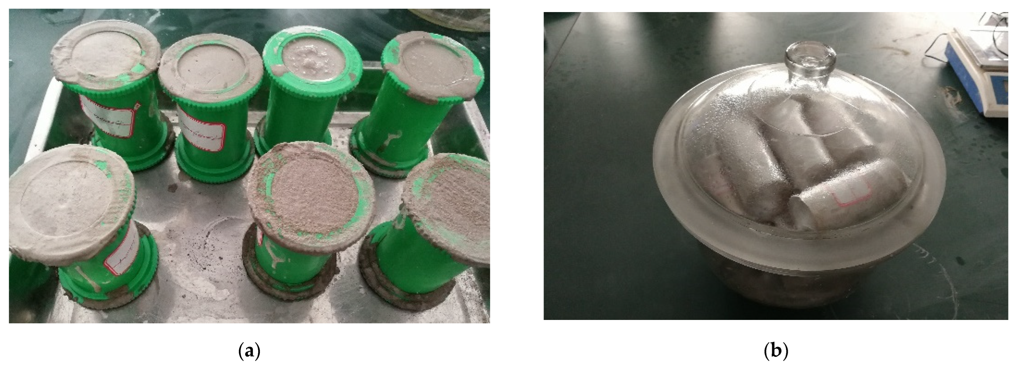
Figure 4.
Test set-up: (a) hydraulic universal testing machine; (b) layout of strain gauges.
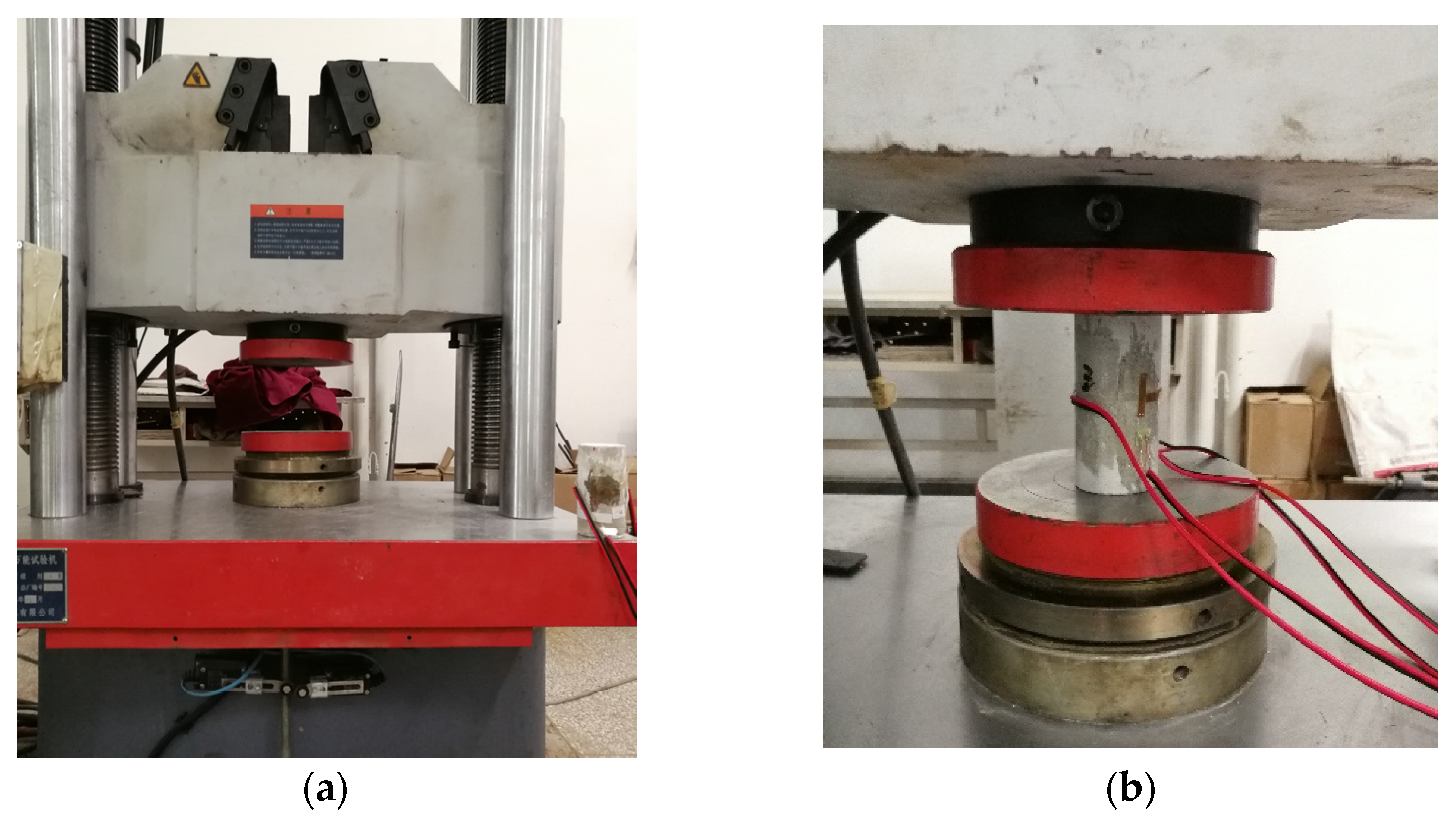
Figure 5.
Evaluation of initial setting time and final setting time.

Figure 6.
Typical failure modes of MBM specimens: (a) as = 0% and three different w/c (1.0, 1.5, and 2.0); (b) as = 60% and three different w/c (1.0, 1.5, and 2.0); (c) w/c = 1.0 and different as (20% and 40%). Herein, as is the sand content, w/c is the water-cement ratio.
Figure 6.
Typical failure modes of MBM specimens: (a) as = 0% and three different w/c (1.0, 1.5, and 2.0); (b) as = 60% and three different w/c (1.0, 1.5, and 2.0); (c) w/c = 1.0 and different as (20% and 40%). Herein, as is the sand content, w/c is the water-cement ratio.

Figure 7.
Stress–strain curve of MBM specimens: (a) as = 0% and three different w/c (1.0, 1.5, and 2.0); (b) as = 60% and three different w/c (1.0, 1.5, and 2.0); (c) w/c = 1.0 and different as (20% and 40%); (d) w/c = 1.5 and different as (0% and 60%); (e) w/c = 2.0 and different as (0% and 60%). Herein, as is the sand content, w/c is the water-cement ratio.
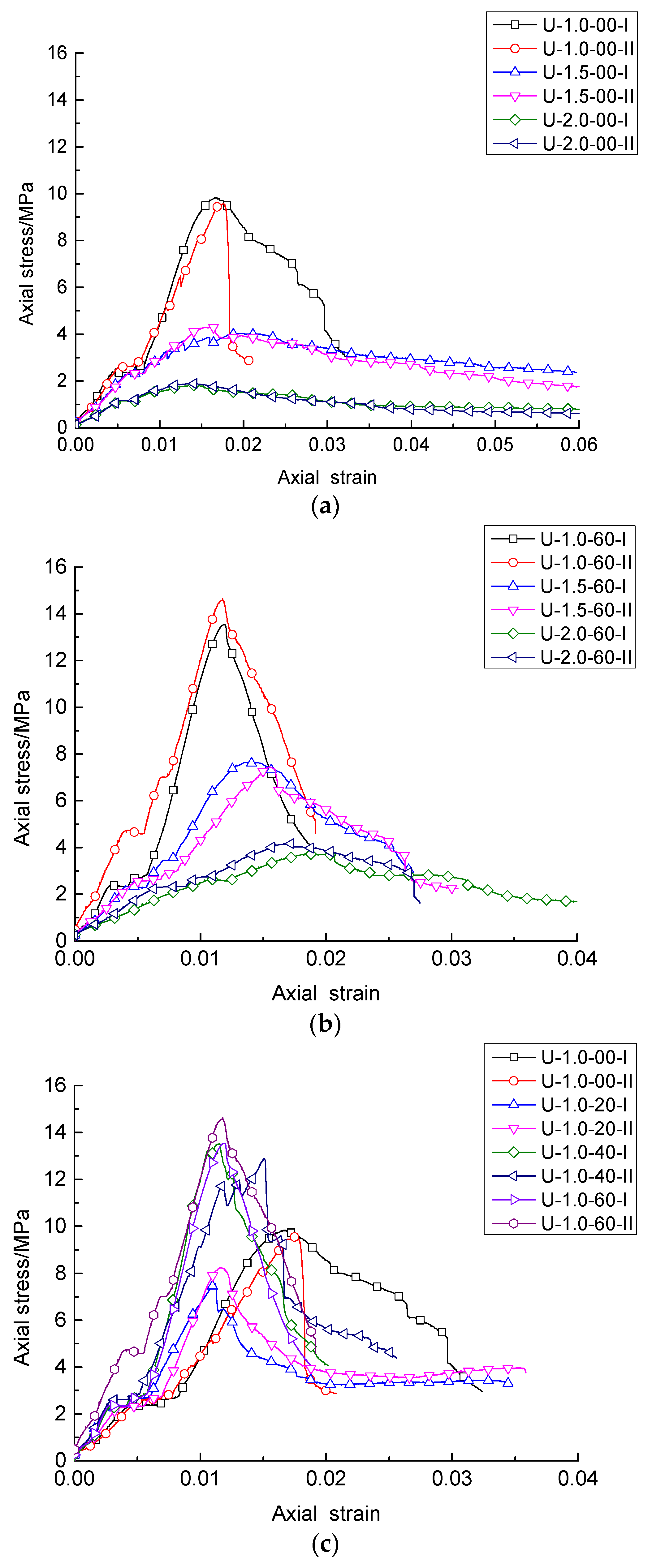
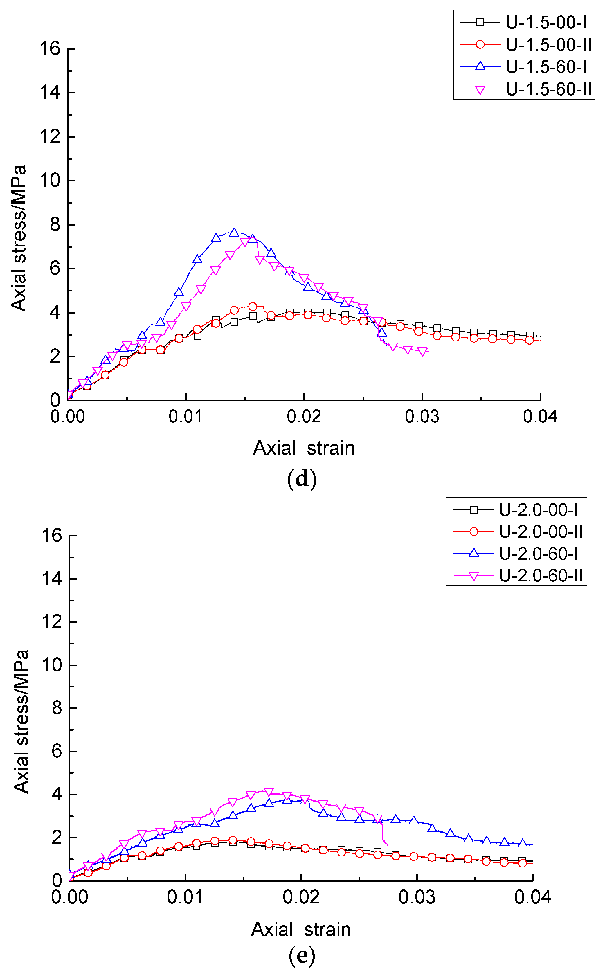
Figure 8.
Consumption of raw materials: (a) Uniaxial compressive strength of specimens of different groups; (b) The percentage of water and cementitious material consumed by specimens of different groups.
Figure 8.
Consumption of raw materials: (a) Uniaxial compressive strength of specimens of different groups; (b) The percentage of water and cementitious material consumed by specimens of different groups.
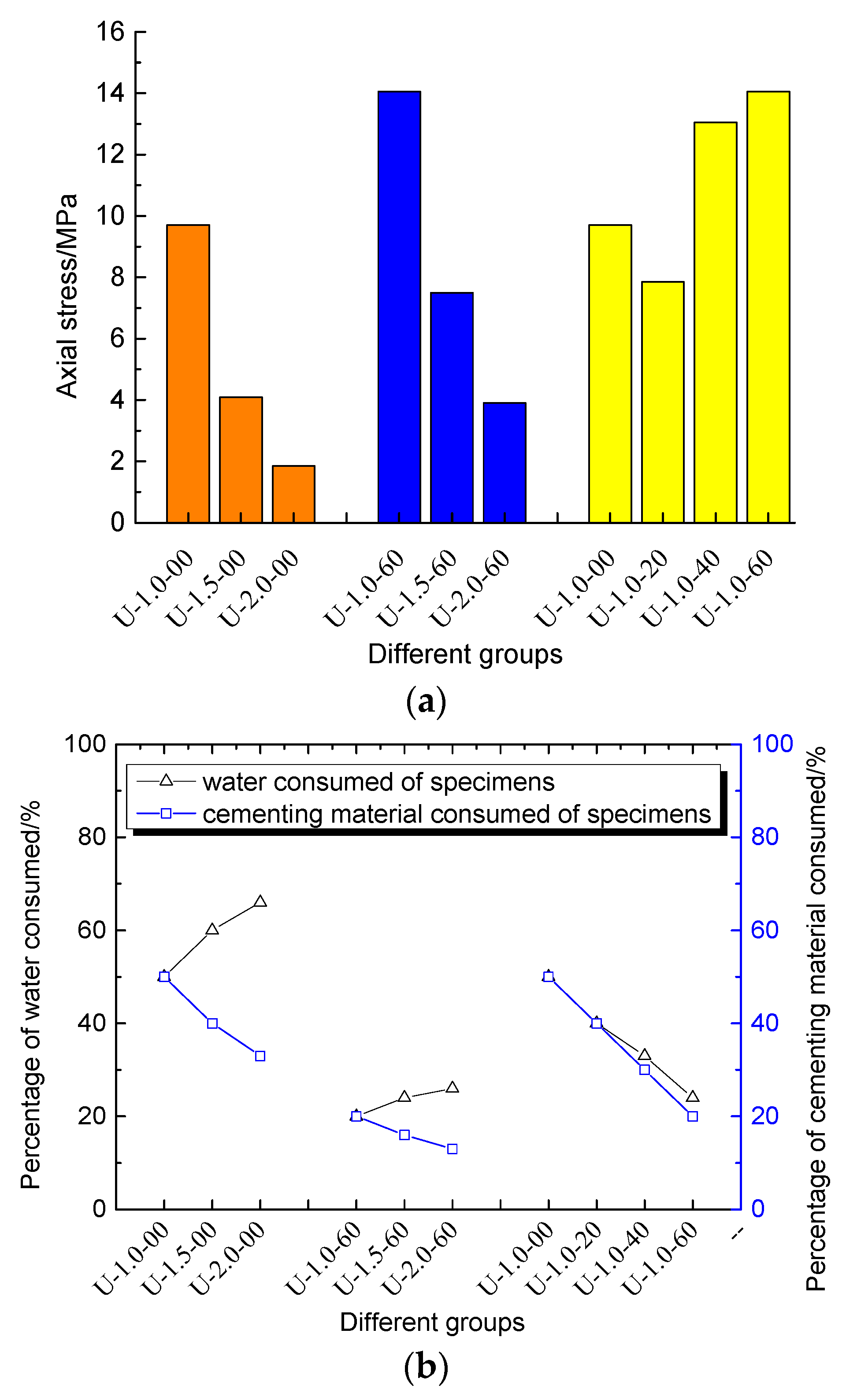
Figure 9.
SEM images of MBM specimens: (a) as = 0% and three different w/c (1.0, 1.5, and 2.0); (b) as = 60% and three different w/c (1.0, 1.5, and 2.0) [31]; (c) w/c = 1.0 and different as (20% and 40%). Herein, as is the sand content, w/c is the water-cement ratio.
Figure 9.
SEM images of MBM specimens: (a) as = 0% and three different w/c (1.0, 1.5, and 2.0); (b) as = 60% and three different w/c (1.0, 1.5, and 2.0) [31]; (c) w/c = 1.0 and different as (20% and 40%). Herein, as is the sand content, w/c is the water-cement ratio.

Table 1.
Details of specimens.
| Series | Group | Specimen | Water−Cement Ratio (w/c) | Sand Content (as) |
|---|---|---|---|---|
| 1 | U-1.0-00 | U-1.0-00-I,II | 1.0 | 0% |
| U-1.5-00 | U-1.5-00-I,II | 1.0 | 0% | |
| U-2.0-00 | U-2.0-00-I,II | 1.0 | 0% | |
| 2 | U-1.0-60 | U-1.0-60-I,II | 1.0 | 60% |
| U-1.5-60 | U-1.5-60-I,II | 1.5 | 60% | |
| U-2.0-60 | U-2.0-60-I,II | 2.0 | 60% | |
| 3 | U-1.0-00 | U-1.0-00-I,II | 1.0 | 0% |
| U-1.0-20 | U-1.0-20-I,II | 1.0 | 20% | |
| U-1.0-40 | U-1.0-40-I,II | 1.0 | 40% | |
| U-1.0-60 | U-1.0-60-I,II | 1.0 | 60% |
Disclaimer/Publisher’s Note: The statements, opinions and data contained in all publications are solely those of the individual author(s) and contributor(s) and not of MDPI and/or the editor(s). MDPI and/or the editor(s) disclaim responsibility for any injury to people or property resulting from any ideas, methods, instructions or products referred to in the content. |
© 2022 by the authors. Licensee MDPI, Basel, Switzerland. This article is an open access article distributed under the terms and conditions of the Creative Commons Attribution (CC BY) license (https://creativecommons.org/licenses/by/4.0/).
Share and Cite
MDPI and ACS Style
Li, G.; Wang, H.; Liu, Z.; Liu, H.; Yan, H.; Liu, Z. Effects of Aeolian Sand and Water−Cement Ratio on Performance of a Novel Mine Backfill Material. Sustainability 2023, 15, 569. https://doi.org/10.3390/su15010569
AMA Style
Li G, Wang H, Liu Z, Liu H, Yan H, Liu Z. Effects of Aeolian Sand and Water−Cement Ratio on Performance of a Novel Mine Backfill Material. Sustainability. 2023; 15(1):569. https://doi.org/10.3390/su15010569
Chicago/Turabian StyleLi, Guodong, Hongzhi Wang, Zhaoxuan Liu, Honglin Liu, Haitian Yan, and Zenwei Liu. 2023. "Effects of Aeolian Sand and Water−Cement Ratio on Performance of a Novel Mine Backfill Material" Sustainability 15, no. 1: 569. https://doi.org/10.3390/su15010569
Note that from the first issue of 2016, this journal uses article numbers instead of page numbers. See further details here.