Article

Characteristics of Pressure Stimulated Current and Damage Evolution of Granite under Progressive Uniaxial Loading

1
School of Safety Engineering, China University of Mining and Technology, Xuzhou 221116, China
2
School of Resources and Geosciences, China University of Mining and Technology, Xuzhou 221116, China
3
Shenzhen Urban Public Safety Technology Research Institute Co., Ltd., Shenzhen 518000, China
4
Xuzhou Jinglan New Material Technology Co., Ltd., Xuzhou 221000, China
*
Authors to whom correspondence should be addressed.
Sustainability 2023, 15(19), 14526; https://doi.org/10.3390/su151914526
Submission received: 4 September 2023 / Revised: 2 October 2023 / Accepted: 2 October 2023 / Published: 6 October 2023
(This article belongs to the Collection Mine Hazards Identification, Prevention and Control)

Abstract

:
The application of load on rock materials stimulates a weak current known as Pressure Stimulated Current (PSC). This study focuses on investigating the damage evolution of granite rocks through the analysis of PSC responses. Uniaxial loading experiments were conducted on granite samples, and the accompanying PSC was measured in real-time. The relationship between PSC characteristics and mechanical behaviors of granite was examined to explore precursory information related to granite failure. The damage evolution of granite was assessed using a damage variable defined as the cumulative charge (time integral of PSC). The results clearly demonstrate a close correlation between the variation of PSC and the mechanical behaviors of rock. Specifically, during the compaction and elastic deformation stages, PSC exhibits a slow and linear increase. However, once deformation enters the plastic stage, PSC demonstrates an accelerated upward trend. Additionally, it was observed that a stress drop coincides with an abnormal increase in PSC, which is followed by a rapid decay. The fluctuation observed after the abnormal increase in PSC during the accelerated growth phase can serve as a precursor of rock failure. Furthermore, the cumulative charge quantity effectively correlates with the damage process of granite samples. The stress–strain curve obtained from a theoretical constitutive model, established based on the damage variable represented by normalized cumulative charge, aligns reasonably well with the experimental results, affirming that the defined damage variable accurately reflects the damage evolution process of rocks. It is hypothesized that PSCs are carried by electrons within the rocks, which are stimulated by electron diffusion during deformation and experience a sharp increase upon rock fracturing. The research findings hold theoretical significance for predicting rockburst incidents using the PSC method.

1. Introduction

Rockburst, a geological disaster resulting from the sudden release of accumulated elastic deformation energy along the free face of underground engineering, poses a significant threat to human lives and property [1]. The occurrence process and severe consequences of rockburst make it a global problem in deep underground engineering, hindering efficient development and utilization of underground space and resources [2,3,4]. The process of rockburst evolution primarily involves the accumulation of damage in rock mass, with sudden rock failure being the direct cause [5,6,7]. Therefore, studying the damage evolution process of rocks is crucial for rockburst prediction.
During the deformation and fracture of rocks under loading, a weak current known as Pressure Stimulated Current (PSC) can be generated [8,9,10,11,12,13]. The variation of PSC is closely associated with the mechanical behaviors of rock materials. Stavrakas et al. [10] observed a significant increase in PSC when stress exceeds approximately 0.6 times the peak stress of marble specimens, with the peak current being directly proportional to the loading rate. Triantis et al. [11] suggested that PSC arises from changes in Young’s modulus rather than the loading rate. Kyriazopoulos et al. [14] proposed that the magnitude of PSC is directly proportional to the strain rate, and fracture occurrence is accompanied by a sudden increase in PSC. Freund et al. [12,15,16,17] found that weak current generated from igneous rocks increases rapidly even at low stress levels and is influenced by the silicate particle content of rocks. Li et al. [13,18] observed that PSC exhibits different responses in various deformation stages of rock materials and increases with the strain rate. Additionally, Li et al. [19] discovered different patterns of PSC changes in rocks under low and high loading rates. Moreover, PSC serves as a reliable indicator of the damage evolution in rock materials and exhibits precursor responses to failure. Triantis et al. [20] detected clear indications of the breaking stress of cement mortar based on PSC, which can be used for predicting final failure. Vallianatos and Triantis [21] introduced non-extensive statistical mechanics (NESM) to study the characteristics of PSC from marble and amphibolite, and the behavior of the Tsallis q-parameter indicates that the rock fracturing is a subadditive process with hierarchically constrained dynamics. Subsequently, Stergiopoulos et al. [22] studied PSCs from mortar beams using NESM and found that the change of q-parameter can be used to predict the failure and instability of cement mortar materials. Li et al. [13] identified an accelerated increase in PSC as a precursor of rock failure under progressively increasing loads, while pulsed fluctuations in PSC serve as precursors to creep rupture. Stavrakas et al. [23] investigated the spatiotemporal evolution of damage in marble specimens under uniaxial compression using PSC and acoustic emission (AE) techniques, demonstrating that both PSC and AE can be employed as pre-failure indicators. Triantis et al. [24] conducted a study investigating the relationship between PSC and AE in brittle materials near fracture load levels. Their findings revealed that the precursor to failure based on weak currents precedes that of AE. Similarly, Loukidis et al. [25] conducted research on the correlation between AE and PSC in the vicinity of fractures in cement mortars during uniaxial compressive loading, yielding similar results. Li et al. [26] conducted a study on the mechanical behaviors of coal under concentrated load conditions and examined the response of PSCs in this context. Based on their findings, they proposed principles for using the PSC technique in predicting rock dynamic disasters. Subsequently, Li et al. [18] successfully measured weak currents in an underground coal mine using their specially developed mine-used weak current monitoring equipment. Their investigation revealed that weak currents exhibit an advance response to mine seismicity. Therefore, the use of the PSC technique for rockburst prediction in underground engineering is considered feasible.
The damage evolution of rocks can be quantitatively characterized by a damage variable, which has been extensively studied in the literature [27,28]. This variable can be defined based on mechanical property parameters and emitted physical signals, enabling a comprehensive understanding of the damage process [29,30]. In the context of the strain equivalence hypothesis, Lemaitre [31] proposed an expression for the damage variable defined by elastic modulus. Jin et al. [32] defined the damage variable for rocks based on energy dissipation and provided a theoretical calculation formula, as well as a method for determining the damage threshold. They utilized this approach to study the damage evolution law of rock materials. Liu et al. [33] introduced a damage variable for rocks based on the normalized cumulative ring-down count of AE signals. They further developed a damage model for coal-rock under uniaxial compression, which facilitated the investigation of the damage evolution law. Li et al. [34] defined the damage variable for sandstone based on electrical resistivity and proposed a comprehensive damage variable capable of effectively reflecting and describing the damage evolution process of rock samples subjected to progressive loading. Gong et al. [30] established a damage constitutive model for brittle rock under uniaxial compression by utilizing a damage variable derived from the linear energy dissipation law. However, the quantitative description of damage evolution in rocks using a damage variable defined by PSCs has not been reported in the literature. This knowledge gap hinders a deep understanding of the generation mechanism of PSCs in rocks and limits the broader application of the PSC technique in rockburst prediction.
In this paper, the response characteristics of PSCs from granite samples under a progressive uniaxial load are investigated. The damage variable based on cumulative charge is defined, and the damage evolution formula is derived, allowing for further analysis of the damage evolution process. The precursor information of rock failure based on PSCs is determined. Furthermore, a potential generation mechanism of PSCs from rocks during deformation and fracture is proposed. Lastly, the application of the PSC method in rockburst prediction is discussed.

2. Material and Method

2.1. Specimen Preparation

The granite blocks used in this study were obtained from a mine located in Shandong, China. To prepare the specimens, twelve cylindrical samples with a diameter of 50 mm and a height of 100 mm were cored and cut from the blocks, following the standards set by the International Society for Rock Mechanics [35]. After the cylindrical samples were obtained, the surfaces of each specimen were meticulously ground to achieve a flat and uniform surface. This step was crucial to ensure proper contact and alignment during the subsequent experimental procedures.

2.2. System and Equipment

The experimental system was comprised of a loading system, a weak current measuring system, and an electromagnetic shielding system (Figure 1). To apply the load, the YAW4306 compression testing machine from MTS Industrial Systems (China) Co., Ltd., Shanghai, China was utilized. The loading process was controlled, and mechanical parameters such as stress and strain were recorded using the Power Test V3.3 software from SANS (Shanghai) Enterprise Development Co., Ltd., Shanghai, China. The weak current measuring system included a Keithley 6517B electrometer from Tektronix (China) Co., Ltd., Shanghai, China, a computer, data acquisition software, a tri-coaxial cable, and electrodes. To minimize the interference of surrounding electrical noise, the experiments were conducted in an electromagnetic shielding room.

2.3. Experimental Procedures and Schemes

Figure 1 illustrates the experimental setup used in this study. Two oblong copper electrodes, measuring 30 mm × 20 mm, were affixed to the side of a granite specimen using conductive silver paint. Insulating tape was used to secure the electrodes in place and prevent detachment. The electrodes were connected to the electrometer via a tri-coaxial cable equipped with alligator clips. To provide electrical insulation, the sample was positioned between two polytetrafluoroethylene plates with an 80 mm diameter and 2 mm thickness. Prior to each test, the press was adjusted to ensure that the upper insulation sheet was approximately one millimeter away from the loading head. A load of 200 N was then applied at a rate of 0.2 mm/min and maintained until the current reached a stable state. The experimental scheme involved subjecting the granite specimens to a progressive uniaxial load at constant rates of 0.1 MPa/s, 0.2 MPa/s, and 0.5 MPa/s until the failure occurred.

3. Results and Analysis

3.1. PSC Response Characteristics

Due to the similarity of the results, the results of Specimens GLS01, GLS02, and GLS03 was selected for analysis. Figure 2 illustrates the variation of stress and PSC with time throughout the entire uniaxial loading process for these three specimens. Notably, the PSC variations from these specimens exhibit similar trends. Based on the PSC-time curve, the variation of PSC can be categorized into two distinct stages:
(I) Slow Increase Phase: During this phase, the PSC values are initially very small and exhibit a gradual and slow increase. The increase in PSC is approximately linear with the increase in stress.
(II) Accelerating Increase Phase: In this phase, the PSC demonstrates an accelerated increasing trend, eventually reaching its peak value at the point of failure. Subsequently, the PSC abruptly decreases.
To differentiate between these two phases, a stress value called the Current Accelerating Stress (σca) is identified, and the stress represents the stress at which the transition from phase I to phase II occurs. The specific values of σca for the three specimens are listed in Table 1. By analyzing the stress and PSC variations over time for the selected specimens (GLS01, GLS02, and GLS03), the distinct phases of PSC evolution can be observed, providing valuable insights into the behavior of PSCs during the uniaxial loading process.
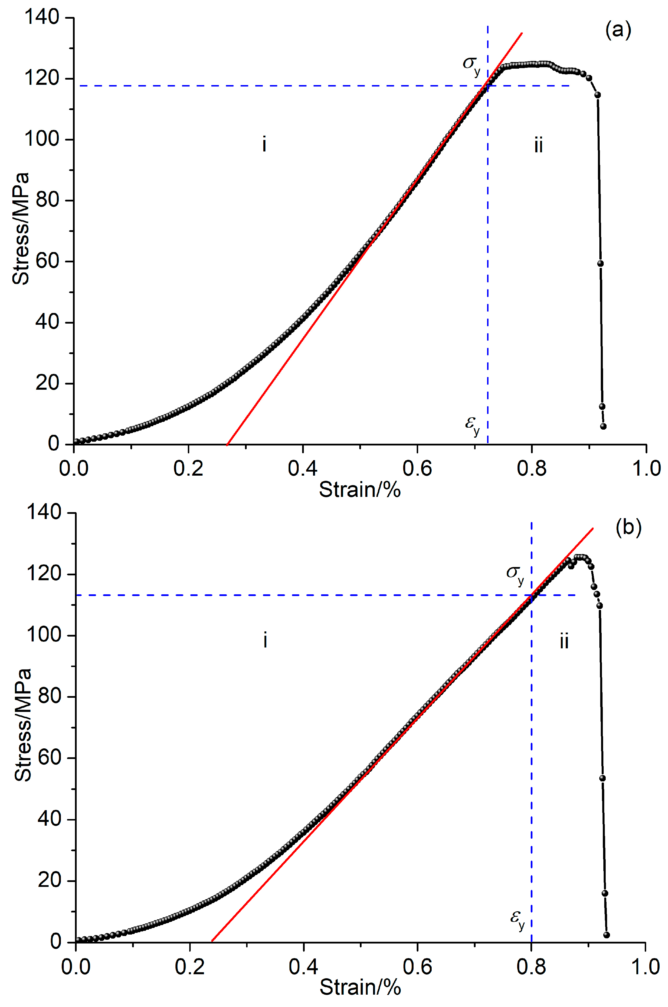
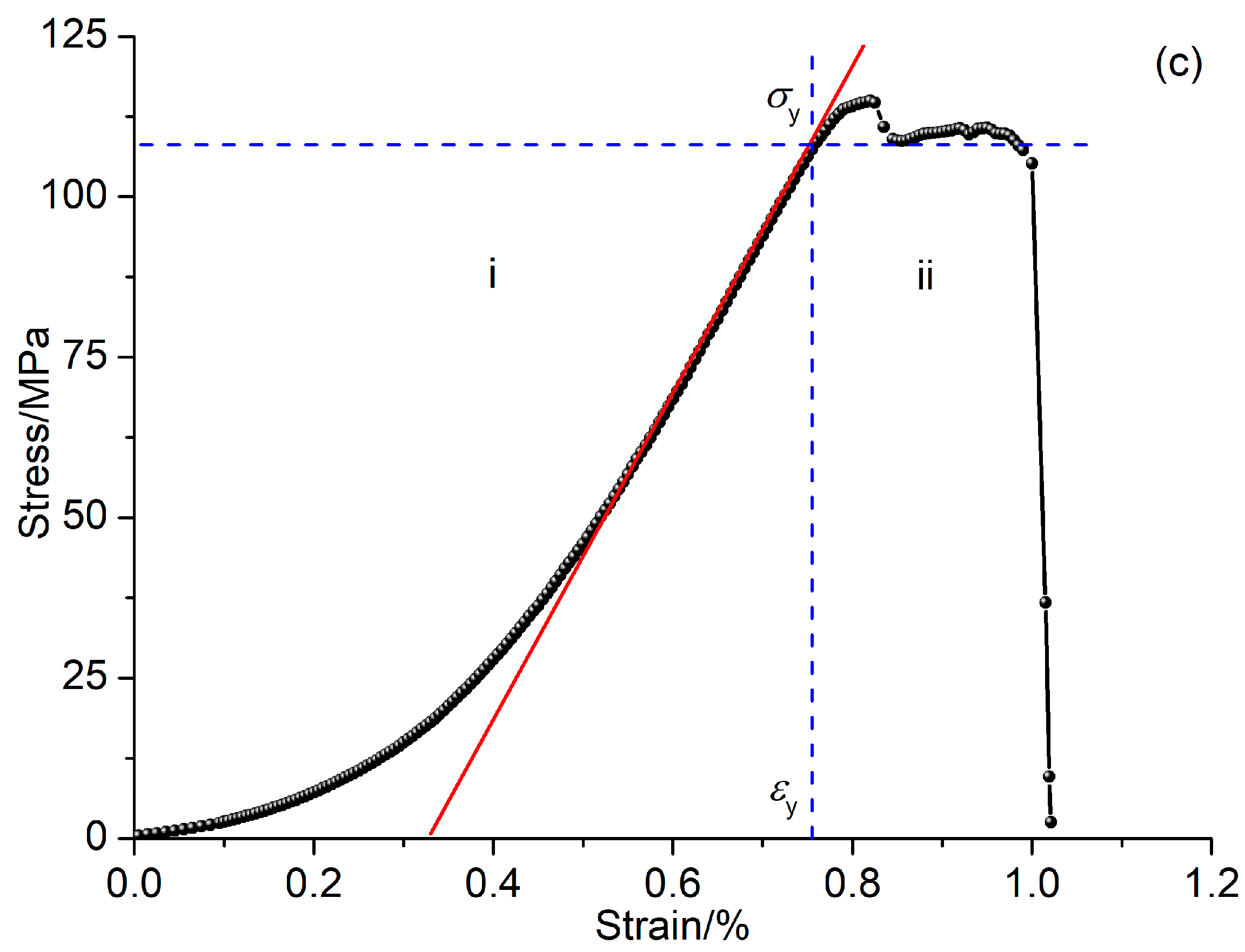
According to the stress–strain curve shown in Figure 3, the deformation of rocks before failure can be divided into three stages: compaction stage, elastic deformation stage, and plastic deformation stage [3]. Each stage is characterized by a different shape of the stress–strain curve. In the compaction stage, the stress–strain curve is concave, indicating a gradual increase in stress with relatively small strain. In the elastic deformation stage, the stress–strain curve is linear, indicating that the material exhibits elastic behavior with stress and strain being proportional to each other. Finally, in the plastic deformation stage, the stress–strain curve becomes convex, indicating a rapid increase in strain with a relatively small increase in stress.
The yield stress (σy) is used to distinguish between the elastic and plastic deformation stages, with the yield strain (εy) corresponding to this transition. Table 1 provides the values of the yield stress (σy) and the Current Accelerating Stress (σac) for specimens GSL01, GSL02, and GSL03. It is observed that the yield stress values are approximately equal to the corresponding Current Accelerating Stress values for all three specimens. This suggests that the point at which the PSC starts to accelerate (σac) is close to the yield stress point (σy).
Based on these observations, it can be concluded that the PSC increases slowly and linearly with stress during the compaction and elastic deformation stages. However, it accelerates during the plastic deformation stage. Therefore, the accelerated increase in PSC can be considered as an indication of the onset of the plastic deformation stage.

3.2. Damage Evolution of Granite Analyzed by PSC

3.2.1. Analytical Expression of Damage Variable

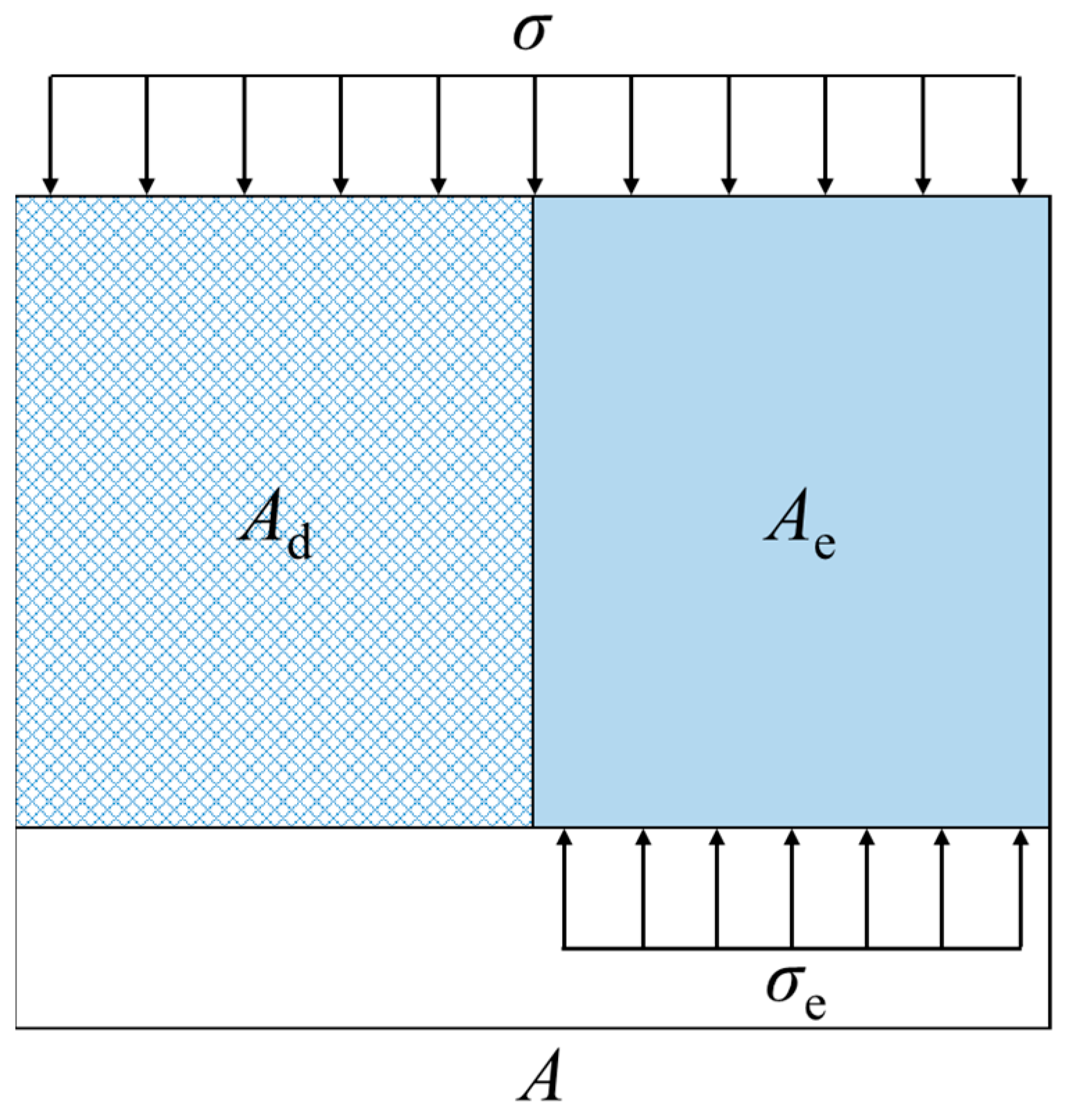
The damage variable, denoted as D, represents the proportion of failed micro elements to the total micro elements in a material. It quantifies the extent of damage or loss of bearing capacity in the material. Kachanov [27] defined the damage variable as the ratio of the area where the material has lost its bearing capacity to the initial area of the material. The damage variable can be calculated by comparing the total area of failure elements on the bearing surface (Ad) with the undamaged or nondestructive area (A), as shown in Figure 4. The calculation equation for the damage variable is as follows:
D = A d A
It is important to note that the damage variable typically ranges between 0 and 1, where D = 0 represents an undamaged material with full bearing capacity, and D = 1 indicates complete failure or loss of bearing capacity.
Due to the loss of bearing capacity in the damaged part (Ad), the applied stress is entirely borne by the undamaged area. This relationship can be expressed by the following equation:
σ A = σ e A e
where σ is the applied stress, σe is the stress in the undamaged area, Ae is the undamaged area, and A is the total area. Then
σ = σ e ( 1 D )
Assuming that the stress and strain of the undamaged part of the element follow Hooke’s law of linear elasticity, the relationship between stress and strain can be expressed as
σ e = E ε
where E is the Young’s modulus of the material, and ε is the strain.
By combining Equations (3) and (4), the following relationship can be derived as
σ = ( 1 D ) E ε
The application of load to the rock induces the movement of charges, leading to the generation of a weak current. If the cumulative charge of complete destruction of the whole section A of the material is Q0, the charge per unit area of destruction (Qw) can be calculated by dividing Q0 by the area of the destructed region (Ad). This can be expressed as
Q w = Q 0 A
When the damaged area of the section reaches Ad, the charge accumulation Qd is calculated using the following formula:
Q d = Q w A d = Q 0 A A d
Then
D = Q d Q 0
In many cases of loading tests, the compression testing machine may stop working before the granite samples are completely damaged. This could be due to the machine’s insufficient stiffness or the different failure conditions set for various samples. Therefore, the traditional definition of the damage variable needs to be modified to account for this incomplete damage [33]. The modified damage variable can be expressed as follows:
D = D u Q d Q 0
where Du is the critical damage variable, and Q0 is the cumulative charge quantity when the damage variable reaches Du. The value of Du can be determined using the following formula:
D u = 1 σ r σ f
where σf represents the peak stress and σr represents the residual stress.
The damage constitutive model for the rock samples under uniaxial compression, derived from cumulative charges, can be expressed as follows:
σ = ( 1 D ) E ε = 1 D u Q d Q 0 E ε

3.2.2. Damage Evolution Law of Granite

The quantity of charge flowing through a section of a rock specimen in a certain period of time can be calculated by integrating the current with respect to time, which corresponds to the area under the current-time curve, as shown in Figure 5. The accumulated charge (Q) can be calculated as follows:
Q = t 1 t 2 I ( t ) d t
The quantity of cumulative charges (Q) in the entire process of rock damage can be calculated by summing up the charges at each time step. This can be expressed as:
Q 0 = 0 t f I ( t ) d t
where I(t) is the current at time t, and tf is the time it takes for the granite specimen to fail finally.
The cumulative charge Qd at any time ti during loading can be calculated by
Q d = 0 t i I ( t ) d t
According to the calculations using Equation (14), the real-time cumulative charge quantity of Specimens GLS01 and GLS02 during the entire loading process was obtained. The variation of cumulative charges with time is depicted in Figure 6. From the figure, it can be observed that the cumulative charge initially exhibits a linear and steady increase. As the loading progresses, the cumulative charge shows an accelerated growth rate. This behavior is consistent with the change in current, indicating a correlation between the cumulative charge and the current. These findings provide valuable insights into the relationship between cumulative charge and the mechanical behavior of the specimens under loading conditions.
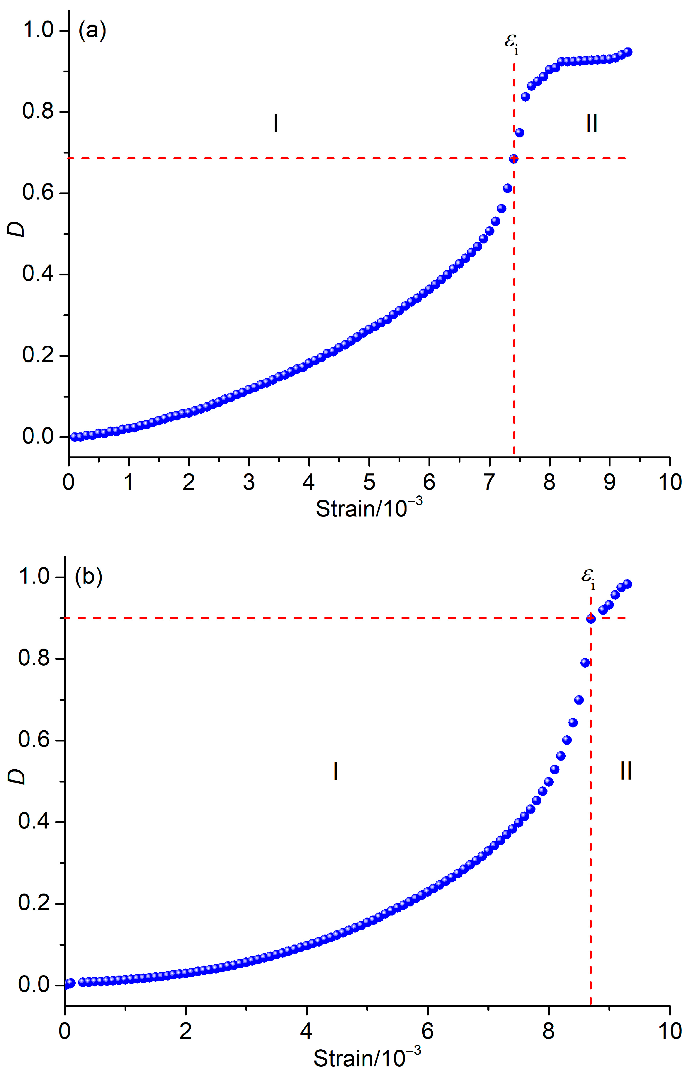
According to the provided data, the residual stresses of Specimens GLS01 and GLS02 are 5.96 MPa and 2.09 MPa, respectively. Using Equations (10) and (13), the parameters Du and Q0 are calculated, and their values are listed in Table 2. By applying Equation (9), the damage variable at any moment can be calculated. The scatter plot of the damage variable (D) with respect to strain (ε) is shown in Figure 7. From the figure, it can be observed that the scatter curve exhibits an inflection point. Before the inflection point, the D-ε curve is concave, indicating a slower increase in the damage variable with strain. After the inflection point, the curve becomes convex, suggesting a more rapid increase in the damage variable with strain.
Therefore, the damage evolution process can be analyzed in two stages, which are divided by the inflection point. The corresponding strain values (εi) for Specimen GLS01 and GLS02 are calculated to be 0.0074 and 0.0087, respectively. These observations highlight the non-linear behavior of the damage evolution process and provide valuable insights into the deformation characteristics of granite specimens under uniaxial compression.
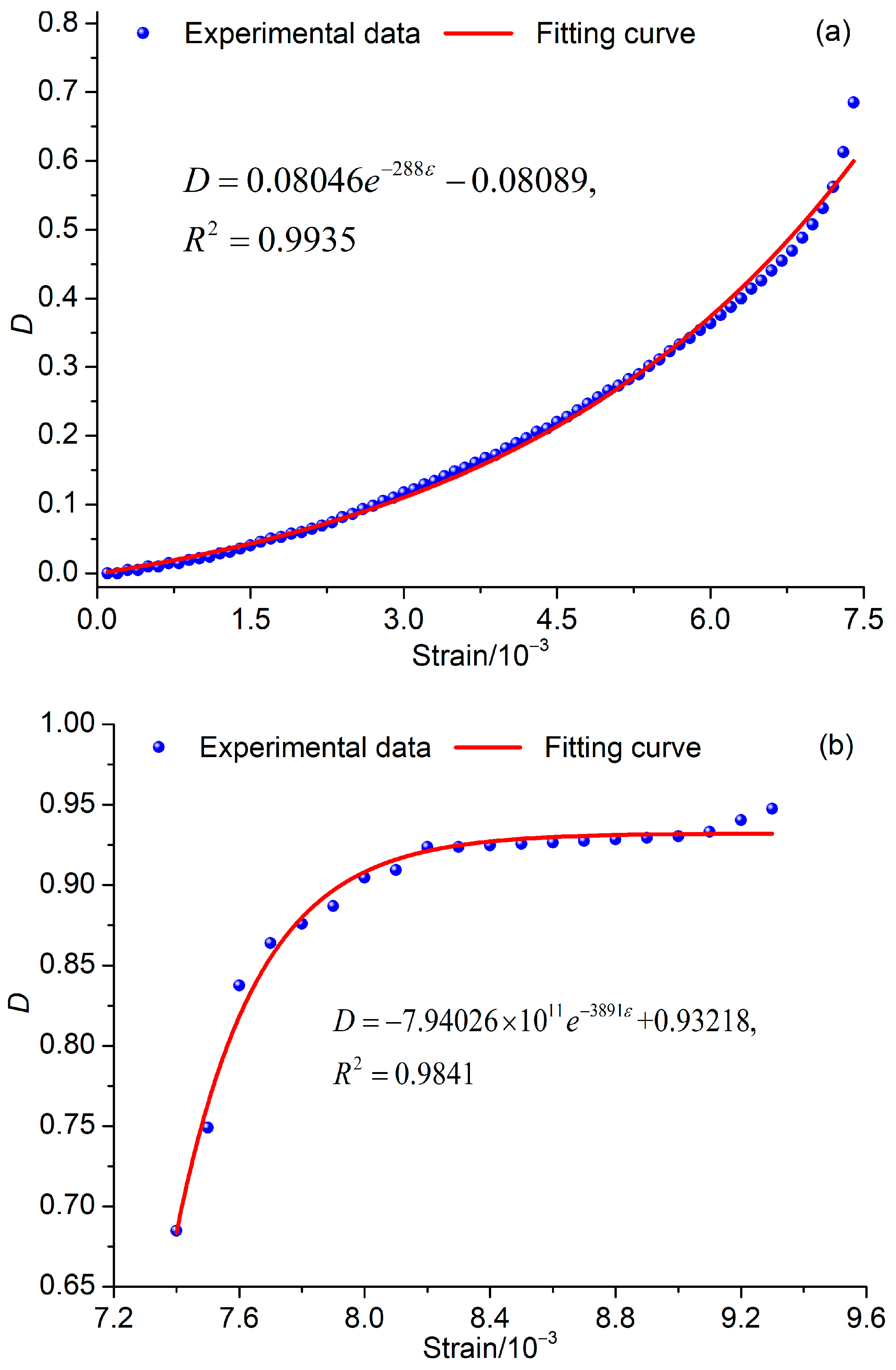
Based on the scatter plot of the damage variable (D) with respect to strain (ε) for Specimen GLS01 (Figure 7a), a piecewise fitting is performed to approximate the damage evolution equation (Figure 8). The deduced equation is as follows:
D = 0.08046 e 288 ε 0.08089   ( 0.0000 ε 0.0074 ) 7.94026 × 10 11 e 3891 ε + 0.93218   ( 0.0074 ε 0.0093 )  
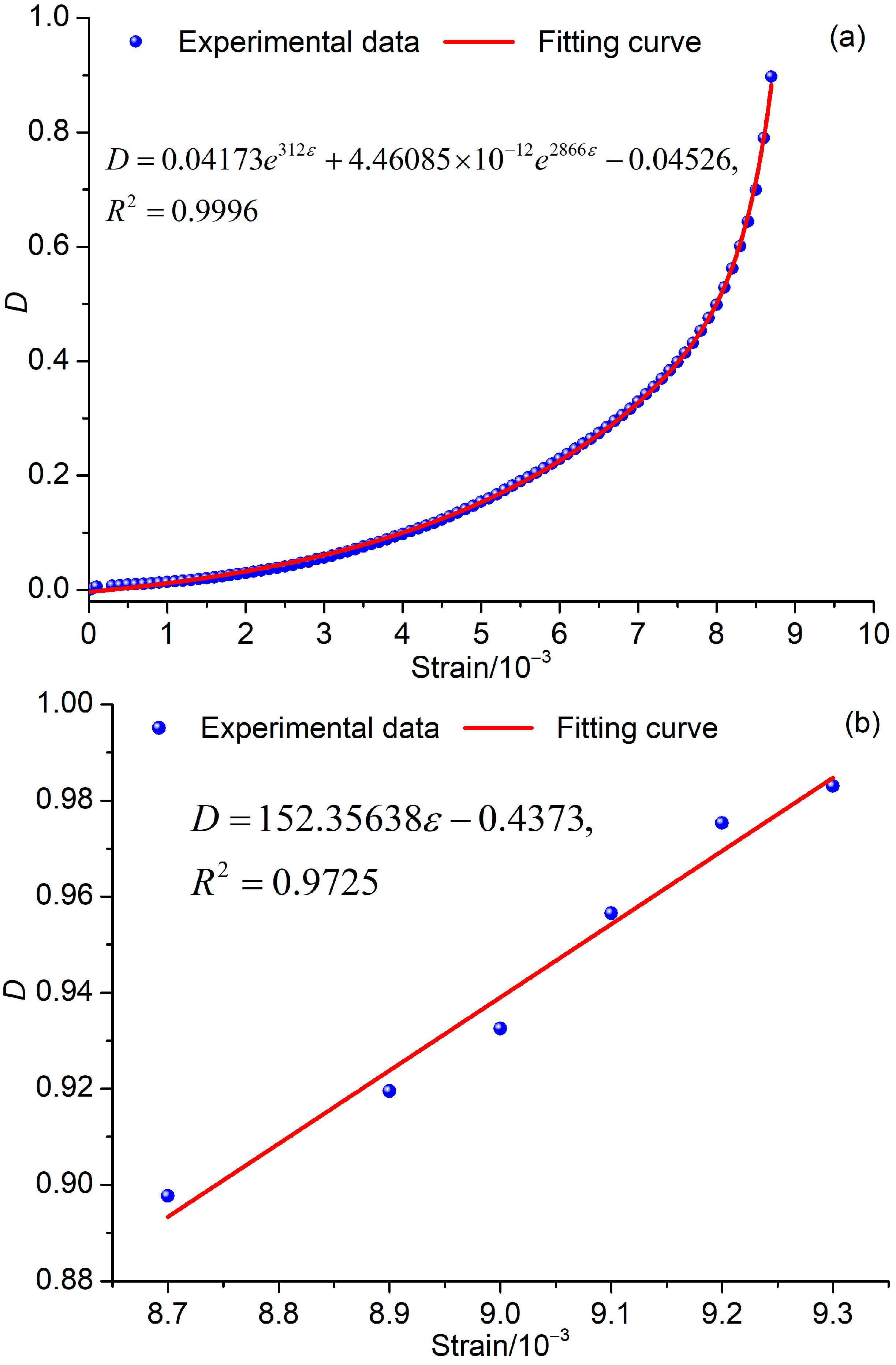
Similarly, based on the scatter plot of the damage variable (D) with respect to strain (ε) for Specimen GLS02 (Figure 7b), a piecewise fitting is performed to deduce the damage evolution equation (Figure 9). The equation is as follows:
D = 0.04173 e 312 ε + 4.46085 × 10 12 e 2866 ε 0.04526   ,   ( 0 ε 0.0087 ) 152.35638 ε 0.4373   ,   ( 0.0087 ε 0.0093 )  

3.2.3. Damage Constitutive Model for Granite

The elastic moduli of Specimens GSL01 and GSL02 were determined by performing linear fitting on the stress–strain curves obtained during the elastic deformation stage. The calculated elastic modulus values for Specimens GSL01 and GSL02 are 30,523 MPa and 22,316 MPa, respectively. By incorporating Equations (11) and (15), the one-dimensional damage constitutive models for Specimens GSL01 and GSL02 based on cumulative charges can be expressed as follows:
σ = 30523 ε ( 1.08089 0.08046 e 288 ε )   ( 0.0000 ε 0.0074 ) 30523 ε ( 7.94026 × 10 11 e 3891 ε + 0.06782 )   ( 0.0074 ε 0.0093 )  
σ = 23316 ε ( 1.04526 0.04173 e 312 ε 4.46085 × 10 12 e 2866 ε )   ,   ( 0 ε 0.0087 ) 23316 ε ( 1.4373 152.35638 ε )   ,   ( 0.0087 ε 0.0093 )  
As depicted in Figure 10, the trend of the theoretical stress–strain curve obtained from the constitutive model aligns with that of the experimental curve. This indicates that the defined damage variable is reasonable and effectively captures the damage progression in granite samples. However, there exists a disparity between the peak limit strains (εp) obtained from the theoretical and experimental curves. To quantify this difference, the stress–strain curve in the elastic deformation stage is extended with a dotted line (Figure 10), intersecting the horizontal axis at the point with coordinates (ε0, 0). In this paper, ε0 is defined as the ideal initial strain. The peak strain offset (Δεp) between the theoretical and experimental failure limit strains can be calculated using the following equation:
Δ ε p = ε p e ε p t
where εpe represents the experimental failure limit strain, and εpt represents the theoretical failure limit strain.
The strain parameters of Specimen GSL01 and GSL02 are provided in Table 3. It can be observed that the ideal initial strain is very close to the peak strain offset, indicating a strong correlation between the difference in peak limit strains and the ideal initial strain. During the initial stages of loading, the rock undergoes compaction, where primary fractures gradually close, leading to an increase in deformation modulus until reaching the elastic deformation stage. This concave-shaped stress–strain curve in the elastic deformation stage results in the presence of an ideal initial strain. Therefore, the deviation between the theoretical and experimental strain-stress curves is primarily influenced by the closure of primary fractures. Based on the analysis, it can be concluded that the damage variable defined by cumulative charge is reasonable and effectively reflects the damage evolution process of granite specimens.

4. Discussion

4.1. Mechanism of PSCs from Granite during Damage

The generation of weak current in granite indicates the presence of carriers within the rock. According to the dielectric conduction theory, there are three forms of carriers: ions, electrons, and holes [36].
Ionic conductivity requires the presence of freely moving ions, which typically occurs in aqueous solutions or molten states. However, in our loading experiments on dry granite at room temperature, there is no condition for the free movement of ions, suggesting that ions are not the carriers of the weak current in this case. Freund [37] and Scoville et al. [16] proposed that p-holes, generated by the loss of an electron by oxygen atoms in silicate minerals, are the main carriers of current in igneous rocks. This theory was also applied to explain the weak current observed in stressed coals [26]. The formation of p-holes involves the fracture of chemical bonds, which requires the absorption of energy. The rapid increase in the weak current suggests the quick formation and movement of a large number of p-holes, indicating the absorption of significant energy that cannot be released during the initial compression stage. Therefore, it is important to note that the main carriers of the weak current are not p-holes.
The above analysis and discussion show that the main carriers of the weak current in rocks are electrons. While a small number of electrons naturally exist in rocks, a significant quantity of electrons can be generated through friction, stress-induced polarization, and crack propagation [26]. These processes provide an ample supply of carriers for the weak current in rocks.
The current is defined as the rate of flow of charge and can be calculated using the formula [36]:
I = d q d t
where I is the current, dq is the change in charge, and dt is the change in time.
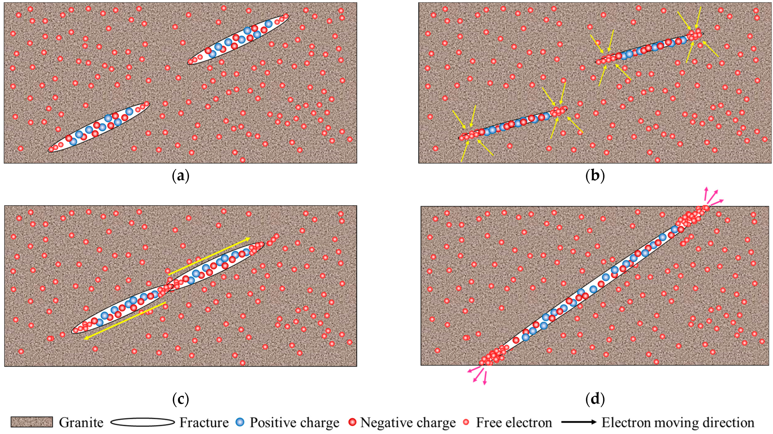
In Figure 11a, when the rock is not loaded, it is in a thermal equilibrium state with free electrons in chaotic motion, resulting in electrical neutrality. However, it should be noted that the distribution of electrons follows the tip effect, where electrons tend to concentrate at the tip of a crack, and the electron density increases with the stress experienced by the crack tip. This means that the electrons in the primary microcracks are not uniformly distributed but rather concentrated at the tip of the crack, resulting in a higher electron density at the crack tip.
In Figure 11b, as the rock is loaded and the cracks start to close, both the original and newly generated free electrons are enriched towards the tip of the primary cracks. This leads to a reduction in charge density in the vicinity of the crack, causing remote charges to flow towards the low-density region to replenish the charge imbalance. This results in the generation of a diffusion current. During the compaction stage, where primary crack closure occurs gradually, the process of charge diffusion is slow. Similarly, during the elastic deformation stage, where the stress at the crack tip does not reach the critical value for crack propagation, the formation and flow of free charges remain slow. Therefore, PSC exhibits a slow and linear increase during the compaction and elastic deformation stages.
As the stress continues to increase, the primary microcracks start to propagate, entering the plastic deformation stage. In this stage, the release of free charges becomes rapid as cracks grow and move towards newly generated crack tips (Figure 11c). With increasing stress, both the number of new cracks and the speed of crack growth gradually increase, accelerating the process of charge transfer and release. As a result, the PSC increases with stress at an accelerated rate during the plastic deformation stage.
In Figure 11d, when the rock fractures due to internal crack coalescence, the accumulated charges at the crack tip are released rapidly, causing a sudden increase in current. This is often referred to as a transient current. Additionally, as the final failure of the rock approaches, the activity of internal crack coalescence becomes more intense, leading to fluctuations in abnormal currents. These current fluctuations can serve as precursors to rock failure.
Overall, the observations in Figure 11 demonstrate that the distribution and movement of electrons in the rock are influenced by stress and crack propagation, leading to the generation and transfer of weak currents. These currents provide valuable insights into the damage evolution process and can serve as indicators of rock failure.

4.2. Application of PSC in Rockburst Prediction

Rockburst, as the name suggests, is a sudden and violent failure of rock mass that occurs during mining and tunnelling activities. The ultimate trigger for a rockburst event is the sudden failure of the rock, which results in the instantaneous release of stored elastic energy [38]. The process of rockburst involves the progressive aggravation of deformation and accumulation of damage in the rock mass.
Before the occurrence of a rockburst, a rock typically undergoes three stages of deformation: the compression stage, elastic deformation stage, and plastic deformation stage. During the compression and elastic deformation stages, the rock experiences deformation and accumulates elastic energy. In these stages, there is minimal crack generation and release of elastic energy, making it unlikely for a rock failure to occur. It is only when the rock enters the plastic deformation stage that local fractures start to develop, accompanied by the generation and propagation of cracks. This stage is critical, as it leads to the failure of the rock under increasing stress. Therefore, the prediction of rockburst events primarily relies on monitoring the deformation of the rock mass and associated physical signals. By closely monitoring the deformation patterns and physical signals, such as changes in stress, strain, AEs, electromagnetic radiations and other relevant parameters, it becomes possible to identify the onset of the plastic deformation stage and the potential for rockburst [39]. Early detection and prediction of rockburst can help mitigate the risks associated with these events and ensure the safety of mining and tunnelling operations.
Based on our experimental results, the damage variable defined by cumulative charge proves to be a reasonable indicator that effectively reflects the damage evolution process of rocks. Therefore, the variation in PSC can be utilized for rockburst prediction. In particular, the behavior of PSC during different deformation stages provides valuable insights. During the compaction and elastic deformation stages, PSC exhibits a slow and gradual increase. However, in the plastic deformation stage, there is an accelerated increase in PSC, which indicates that the rock deformation has entered a critical phase. This continuous acceleration in PSC can serve as an early signal of the transition to plastic deformation.
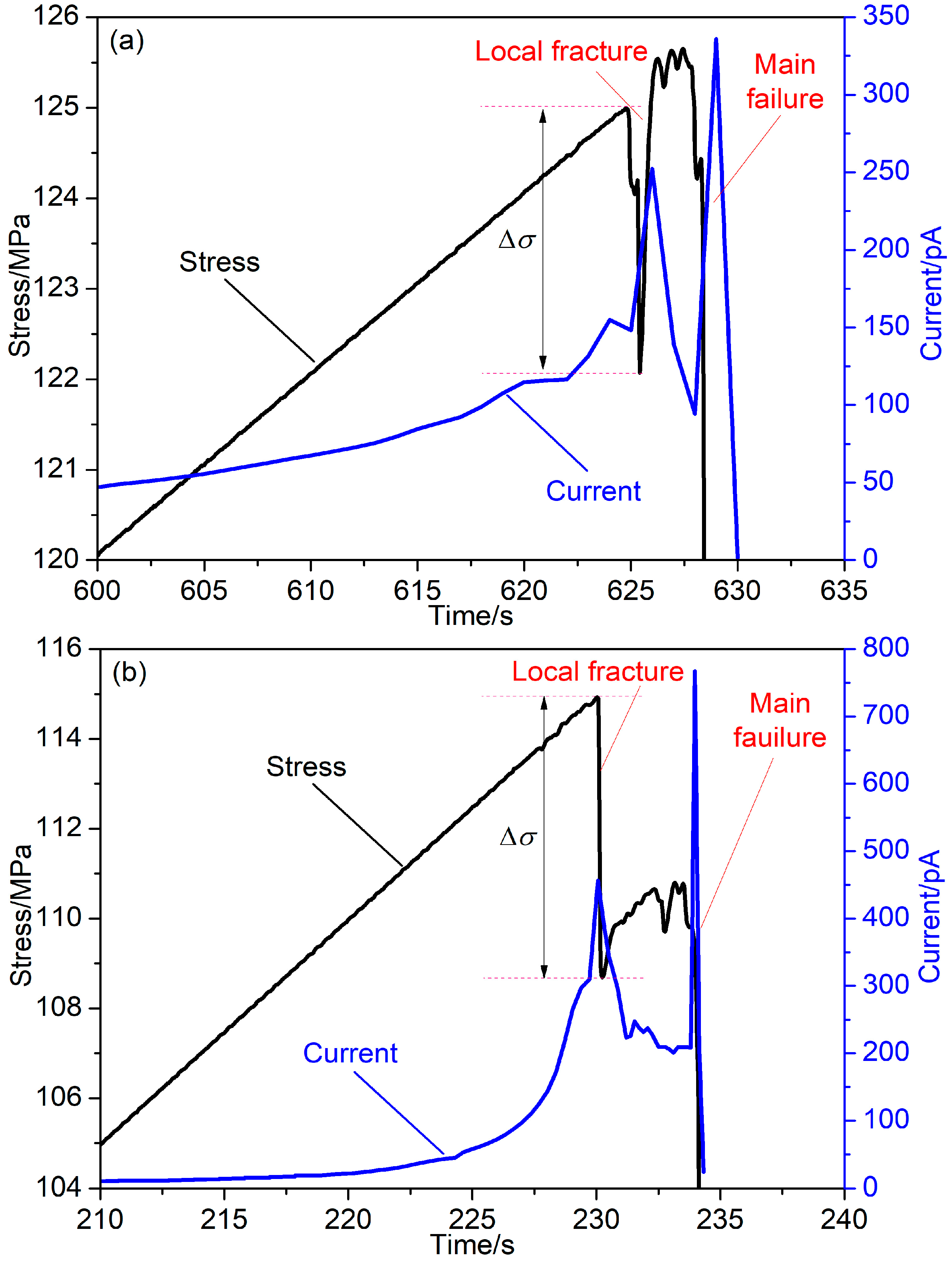
To further analyze the relationship between stress and PSC, we zoomed in on the stress and PSC curves during the period leading up to final failure, as shown in Figure 12. It can be observed that when a stress drop occurs, there is a sharp increase in PSC followed by a rapid decrease, indicating that the fracture is accompanied by an abnormal surge in PSC. Subsequently, PSC fluctuates at a high level and demonstrates a responsive behavior to stress variations. When the final failure occurs, PSC experiences another surge, reaching its peak value. It is noteworthy that after the failure, PSC drops to the background value. In contrast, when a local fracture occurs, PSC may drop slightly but continues to vibrate at a high value, significantly higher than the background level. Therefore, the post-abnormal increase fluctuation in PSC during the accelerated increase process can be regarded as a precursor to rock failure or rockburst.
Considering the strong anti-interference capability and early response to mine seismicity, the PSC technique holds promising potential for broader applications in rockburst prediction [18]. By utilizing the PSC technique, it becomes possible to enhance the ability to detect and forecast rockburst events, contributing to improved safety measures in mining and tunnelling operations.

5. Conclusions

The main conclusions can be summarized as follows:
(1)
PSC can be generated from granite during deformation, and its variation effectively reflects the different deformation stages of the rock. During the compaction and elastic deformation stages, PSC shows a gradual increase with stress. However, after the deformation enters the plastic stage, PSC exhibits an accelerated increase in response to stress.
(2)
PSC exhibits precursory behavior prior to granite failure. A stress drop is accompanied by a sudden and significant increase in PSC, which then decays rapidly. The growth rate and amplitude of the PSC associated with the main fracture are greater compared to those observed during a local fracture. Following the occurrence of the main failure, PSC experiences a sudden drop to pre-loading levels. In the case of a local fracture, PSC decreases slightly and continues to vibrate at a high value. The fluctuation following an abnormal increase in PSC during the accelerated increase process can serve as a precursor to rock failure.
(3)
The cumulative charge calculated based on PSC effectively reflects the damage process of granite samples. The stress–strain curve obtained using a theoretical constitutive model, established according to the defined damage variable based on cumulative charge, is in good agreement with the experimental results. This indicates that the damage variable defined by cumulative charge accurately reflects the damage evolution process of granite.
(4)
The carriers of PSC in rocks are primarily electrons, and their distribution follows the tip effect, with charge enrichment towards the crack tip. The generation mechanism of weak currents during rock damage involves the transfer, accumulation, and release of free charges. During the deformation process, currents are stimulated due to charge diffusion resulting from density differences. When a fracture occurs, currents are stimulated by the rapid release of accumulated charges.

Author Contributions

Conceptualization, D.L., E.W. and J.Y.; Methodology, D.L. and J.Y.; Software, W.L.; Validation, L.L.; Formal analysis, M.L. and D.W.; Investigation, D.L. and D.W.; Data curation, M.L. and W.L.; Writing—original draft, D.L.; Writing—review & editing, E.W. and J.Y.; Supervision, E.W.; Project administration, L.L.; Funding acquisition, D.L. All authors have read and agreed to the published version of the manuscript.

Funding

This research was funded by the National Natural Science Foundation of China (52204257), Jiangsu Funding Program for Excellent Postdoctoral Talent (2022ZB512), the GuangDong Basic and Applied Basic Research Foundation (2022A1515110132), China Postdoctoral Science Foundation (2022M713371) and the Fundamental Research Funds for the Central Universities (2022QN1014).

Institutional Review Board Statement

Not applicable.

Informed Consent Statement

Not applicable.

Data Availability Statement

Data is available on request from the authors.

Conflicts of Interest

The authors declare no conflict of interest.

References

  1. Kaiser, P.K.; McCreath, D.R.; Tannant, D.D. Canadian Rockburst Support Handbook; Geomechanics Research Centre, Laurentian University: Sudbury, ON, Canada, 1996; p. 314. [Google Scholar]
  2. Li, X.B.; Zhou, J.; Wang, S.F.; Liu, B. Review and practice of deep mining for solid mineral resources speed. Chin. J. Nonferrous Met. 2017, 27, 1236–1262. [Google Scholar]
  3. Li, D.X.; Wang, E.Y.; Kong, X.G.; Ali, M.; Wang, D.M. Mechanical behaviors and acoustic emission fractal characteristics of coal specimens with a pre-existing flaw of various inclinations under uniaxial compression. Int. J. Rock Mech. Min. Sci. 2019, 116, 38–51. [Google Scholar] [CrossRef]
  4. Feng, G.L.; Feng, X.T.; Xiao, Y.X.; Yao, Z.B.; Hu, L.; Niu, W.J.; Li, T. Characteristic microseismicity during the development process of intermittent rockburst in a deep railway tunnel. Int. J. Rock Mech. Min. Sci. 2019, 124, 104135. [Google Scholar] [CrossRef]
  5. Keneti, A.; Sainsbury, B.A. Review of published rockburst events and their contributing factors. Eng. Geol. 2018, 246, 361–373. [Google Scholar] [CrossRef]
  6. Li, C.C. Principles and methods of rock support for rockburst control. J. Rock Mech. Geotech. 2021, 13, 46–59. [Google Scholar] [CrossRef]
  7. Luo, S.; Gong, F.Q. Evaluation of energy storage and release potentials of highly stressed rock pillar from rockburst control perspectives. Int. J. Rock Mech. Min. Sci. 2023, 163, 105324. [Google Scholar] [CrossRef]
  8. Vallianatos, F.; Tzanis, A. Electric current generation associated with the deformation rate of a solid: Preseismic and coseismic signals. Phys. Chem. Earth 1998, 23, 933–939. [Google Scholar] [CrossRef]
  9. Vallianatos, F.; Triantis, D.; Tzanis, A.; Anastasiadis, C.; Stavrakas, I. Electric earthquake precursors: From laboratory results to field observations. Phys. Chem. Earth 2004, 29, 339–351. [Google Scholar] [CrossRef]
  10. Stavrakas, I.; Anastasiadis, C.; Triantis, D.; Vallianatos, F. Piezo stimulated currents in marble samples: Precursory and concurrent-with-failure signals. Nat. Hazards Earth Syst. Sci. 2003, 3, 243–247. [Google Scholar] [CrossRef]
  11. Triantis, D.; Stavrakas, I.; Anastasiadis, C.; Kyriazopoulos, A.; Vallianatos, F. An analysis of pressure stimulated currents (PSC), in marble samples under mechanical stress. Phys. Chem. Earth 2006, 31, 234–239. [Google Scholar] [CrossRef]
  12. Freund, F.T.; Takeuchi, A.; Lau, B.W. Electric currents streaming out of stressed igneous rocks—A step towards understanding pre-earthquake low frequency EM emissions. Phys. Chem. Earth 2006, 31, 389–396. [Google Scholar] [CrossRef]
  13. Li, D.X.; Wang, E.Y.; Li, Z.H.; Ju, Y.Q.; Wang, D.M.; Wang, X.Y. Experimental investigations of pressure stimulated currents from stressed sandstone used as precursors to rock fracture. Int. J. Rock Mech. Min. Sci. 2021, 145, 104841. [Google Scholar] [CrossRef]
  14. Kyriazopoulos, A.; Anastasiadis, C.; Triantis, D.; Brown, C.J. Non-destructive evaluation of cement-based materials from pressure-stimulated electrical emission—Preliminary results. Constr. Build. Mater. 2011, 25, 1980–1990. [Google Scholar]
  15. Takeuchi, A.; Lau, B.W.S.; Freund, F.T. Current and surface potential induced by stress-activated positive holes in igneous rocks. Phys. Chem. Earth 2006, 31, 240–247. [Google Scholar] [CrossRef]
  16. Scoville, J.; Sornette, J.; Freund, F.T. Paradox of peroxy defects and positive holes in rocks Part II: Outflow of electric currents from stressed rocks. J. Asian Earth Sci. 2015, 114, 338–351. [Google Scholar] [CrossRef]
  17. Freund, F.; Ouillon, G.; Scoville, J.; Sornette, D. Earthquake precursors in the light of peroxy defects theory: Critical review of systematic observations. Eur. Phys. J. Spec. Top. 2021, 230, 7–46. [Google Scholar]
  18. Li, D.X.; Wang, E.Y.; Feng, X.J.; Wang, D.M.; Zhang, X.; Ju, Y.Q. Weak current induced by coal deformation and fracture and its response to mine seismicity in a deep underground coal mine. Eng. Geol. 2023, 315, 107018. [Google Scholar] [CrossRef]
  19. Li, M.; Lin, Z.J.; Shi, S.L.; Wang, D.M.; Lu, Y.; Li, H.; Ye, Q.; Zhang, X.N. Experimental research on influence mechanism of loading rates on rock pressure stimulated currents. Int. J. Min. Sci. Technol. 2023, 33, 243–250. [Google Scholar] [CrossRef]
  20. Triantis, D.; Stavrakas, I.; Kyriazopoulos, A.; Hloupis, G.; Agioutantis, Z. Pressure stimulated electrical emissions from cement mortar used as failure predictors. Int. J. Fract. 2012, 175, 53–61. [Google Scholar] [CrossRef]
  21. Vallianatos, F.; Triantis, D. A non-extensive view of the Pressure Stimulated Current relaxation during repeated abrupt uniaxial load-unload in rock samples. Europhys. Lett. 2013, 104, 68002. [Google Scholar] [CrossRef]
  22. Stergiopoulos, C.; Stavrakas, I.; Triantis, D.; Vallianatos, F.; Stonham, J. Predicting fracture of mortar beams under three-point bending using non-extensive statistical modeling of electric emissions. Phys. A 2015, 419, 603–611. [Google Scholar]
  23. Stavrakas, I.; Kourkoulis, S.; Triantis, D. Damage evolution in marble under uniaxial compression monitored by pressure stimulated currents and acoustic emissions. Fract. Struct. Integr. 2019, 13, 573–583. [Google Scholar] [CrossRef]
  24. Triantis, D.; Pasiou, E.D.; Stavrakas, I.; Kourkoulis, S.K. Hidden affinities between electric and acoustic activities in brittle materials at near-fracture load levels. Rock Mech. Rock Eng. 2022, 55, 1325–1342. [Google Scholar]
  25. Loukidis, A.; Tzagkarakis, D.; Kyriazopoulos, A.; Stavrakas, I.; Triantis, D. Correlation of acoustic emissions with electrical signals in the vicinity of fracture in cement mortars subjected to uniaxial compressive loading. Appl. Sci. 2023, 13, 365. [Google Scholar] [CrossRef]
  26. Li, D.X.; Wang, E.Y.; Ju, Y.Q.; Wang, D.M. Laboratory investigations of a new method using pressure stimulated currents to monitor concentrated stress variations in coal. Nat. Resour. Res. 2021, 30, 707–724. [Google Scholar] [CrossRef]
  27. Kachanov, M. Effective elastic properties of cracked solids: Critical review of some basic concepts. Appl. Mech. Rev. 1992, 45, 304–335. [Google Scholar] [CrossRef]
  28. Voyiadjis, G.Z.; Kattan, P.I. A comparative study of damage variables in continuum damage mechanics. Int. J. Damage Mech. 2009, 18, 315–340. [Google Scholar] [CrossRef]
  29. Xiao, J.Q.; Ding, D.X.; Jiang, F.L.; Xu, G. Fatigue damage variable and evolution of rock subjected to cyclic loading. Int. J. Rock. Mech. Min. Sci. 2010, 47, 461–468. [Google Scholar] [CrossRef]
  30. Gong, F.Q.; Zhang, P.L.; Xu, L. Damage constitutive model of brittle rock under uniaxial compression based on linear energy dissipation law. Int. J. Rock. Mech. Min. Sci. 2022, 160, 105273. [Google Scholar] [CrossRef]
  31. Lemaitre, J. How to use damage mechanics. Nucl. Eng. Des. 1984, 80, 233–245. [Google Scholar] [CrossRef]
  32. Jin, F.N.; Jiang, M.R.; Gao, X.L. Defining damage variable based on energy dissipation. Chin. J. Rock Mech. Eng. 2004, 23, 1976–1980. [Google Scholar]
  33. Liu, B.X.; Huang, J.L.; Wang, Z.Y.; Liu, L. Study on damage evolution and acoustic emission character of coal-rock under uniaxial compression. Chin. J. Rock Mech. Eng. 2009, 28, 3234–3238. [Google Scholar]
  34. Li, S.C.; Xu, X.J.; Liu, Z.Y.; Yang, W.M.; Liu, B.; Zhang, X.; Wang, Z.C.; Nie, L.C.; Li, J.L.; Xu, L. Electrical resistivity and acoustic emission response characteristics and damage evolution of sandstone during whole process of uniaxial compression. Chin. J. Rock Mech. Eng. 2014, 33, 14–23. [Google Scholar] [CrossRef]
  35. Barton, N. Suggested methods for the quantitative description of discontinuities in rock masses. International Society for Rock Mechanics. Int. J. Rock Mech. Min. Sci. Geomech. Abstr. 1978, 15, 319–368. [Google Scholar]
  36. Fischer-Cripps, A.C. The Electronics Companion; CRC Press: Boca Raton, FL, USA, 2004. [Google Scholar]
  37. Freund, F.T. Pre-earthquake signals: Underlying physical processes. J. Asian Earth Sci. 2011, 41, 383–400. [Google Scholar]
  38. Kong, X.G.; He, D.; Liu, X.F.; Wang, E.Y.; Li, S.G.; Liu, T.; Ji, P.F.; Deng, D.Y.; Yang, S.R. Strain characteristics and energy dissipation laws of gas-bearing coal during impact fracture process. Energy 2022, 242, 123028. [Google Scholar] [CrossRef]
  39. Qiu, L.M.; Zhu, Y.; Song, D.Z.; He, X.Q.; Wang, W.X.; Liu, Y.; Xiao, Y.Z.; Wei, M.H.; Yin, S.; Liu, Q. Study on the nonlinear characteristics of EMR and AE during coal splitting tests. Minerals 2022, 12, 108. [Google Scholar] [CrossRef]
Figure 1. Experimental system and equipment.
Sustainability 15 14526 g001
Figure 2. Temporal variation of stress and PSC of Specimen (a) GSL01, (b) GSL02 and (c) GSL03. Phases (I) Slow Increase and (II) Accelerating Increase.
Sustainability 15 14526 g002aSustainability 15 14526 g002b
Figure 3. Stress–strain curve of Specimen (a) GSL01, (b) GSL02 and (c) GSL03 during the whole loading. (i) Compaction and elastic deformation stage and (ii) Plastic deformation stage. The red line marks the elastic deformation stage.
Sustainability 15 14526 g003aSustainability 15 14526 g003b
Figure 4. Diagram showing the stress state of an elastoplastic damaged body element.
Sustainability 15 14526 g004
Figure 5. Schematic diagram of charge calculation.
Sustainability 15 14526 g005
Figure 6. Variation of stress and cumulative charge with time of Specimen (a) GSL01 and (b) GSL02.
Sustainability 15 14526 g006
Figure 7. Scatters of damage variable with strain of Specimens (a) GSL01 and (b) GSL02.
Sustainability 15 14526 g007
Figure 8. Piecewise fitting of D-ε scatters of Specimen GSL01 during the whole damage process. (a) 0 < ε ≤ 0.0074; (b) 0.0074 ≤ ε ≤ 0.0093.
Sustainability 15 14526 g008
Figure 9. Piecewise fitting of D-ε scatters of Specimen GSL02 during the whole damage process. (a) 0 < ε ≤ 0.0087; (b) 0.0087 ≤ ε ≤ 0.0093.
Sustainability 15 14526 g009
Figure 10. Theoretical and experimental stress–strain curve of Specimen (a) GLS02 and (b) GLS03.
Sustainability 15 14526 g010
Figure 11. Schematic diagram showing a mechanism of PSCs from rock during deformation and fracture. (a) Unstressed state; (b) Crack closure; (c) Crack propagation; (d) Crack coalescence.
Sustainability 15 14526 g011
Figure 12. Variation of stress and current with time before rock failure. (a) GSL02; (b) GSL03.
Sustainability 15 14526 g012
Table 1. Characteristic stress and strain of the three specimens.
Specimenσca/MPaσy/MPaεy/%
GLS01117.2116.40.720
GLS02112.9113.10.852
GLS03107.5108.20.755
Table 2. The typical stresses and damage variable of Specimen GSL01 and GSL02.
Specimenσf/MPaσr/MPaDu/sQ0/pCεi
GLS01124.95.960.9527309.50.0074
GLS02125.62.090.9838815.60.0087
Table 3. Typical strain parameters of Specimen GSL01 and GSL02.
SpecimenεptεpeΔεpε0
GLS010.006600.008850.002250.00220
GLS020.006950.009600.002650.00330
Disclaimer/Publisher’s Note: The statements, opinions and data contained in all publications are solely those of the individual author(s) and contributor(s) and not of MDPI and/or the editor(s). MDPI and/or the editor(s) disclaim responsibility for any injury to people or property resulting from any ideas, methods, instructions or products referred to in the content.