
Numerical Multifield Coupling Model of Stress Evolution and Gas Migration: Application of Disaster Prediction and Mining Sustainability Development

Abstract
:1. Introduction
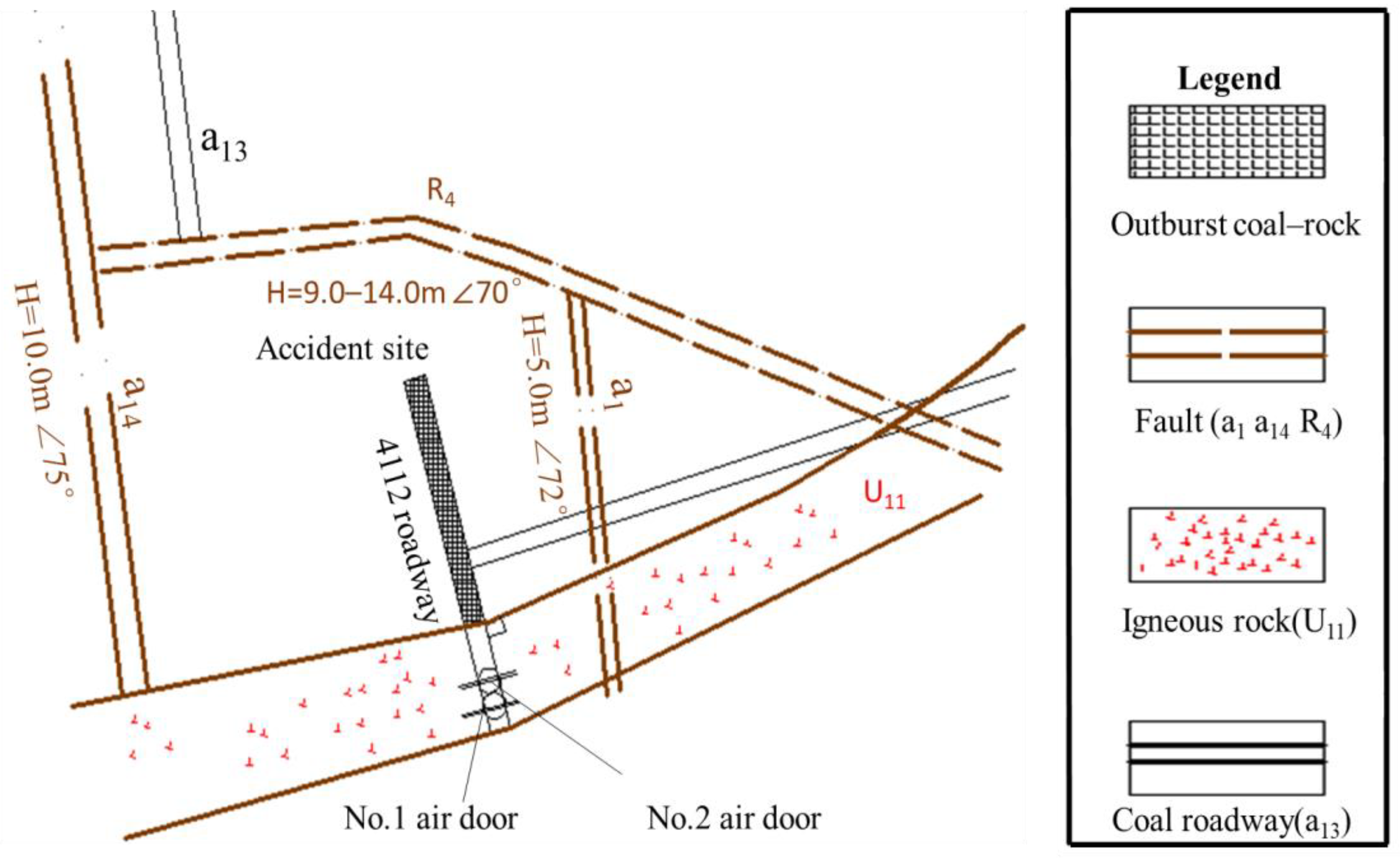
2. Mine Background
3. Numerical Simulation of Disaster Case
3.1. Basic Model and Assumptions
- (1)
- Impact-dynamics constitutive equation of gas-bearing coal
- (2)
- Gas desorption, diffusion, seepage, and emission equations
- (3)
- Porosity and permeability control equations
- (1)
- Gas seepage is not involved in the coal matrix, and gas diffusion is not involved in the coal seam, then it can also enter the adjacent rock strata. The gas pressure was the average measured value of 1.2 MPa.
- (2)
- The 4112 tunneling face has been excavated once, regardless of filling and supporting.
- (3)
- The average coal seam thickness in the corresponding local area of the accident site is the model’s geological condition parameter.
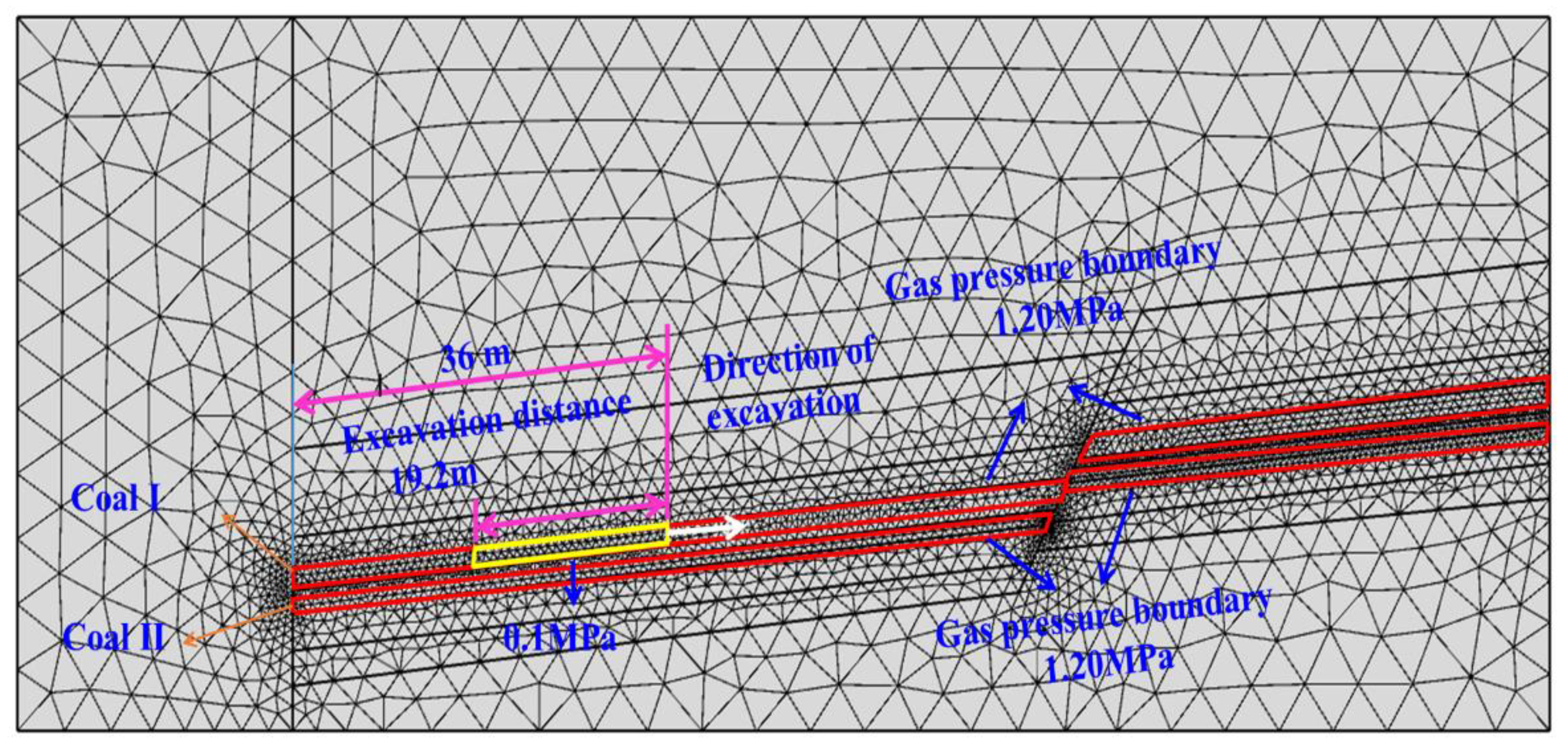
3.2. Geometric Model and Boundary Conditions
- (1)
- Boundaries of the solid mechanics modules
- (2)
- PDE module
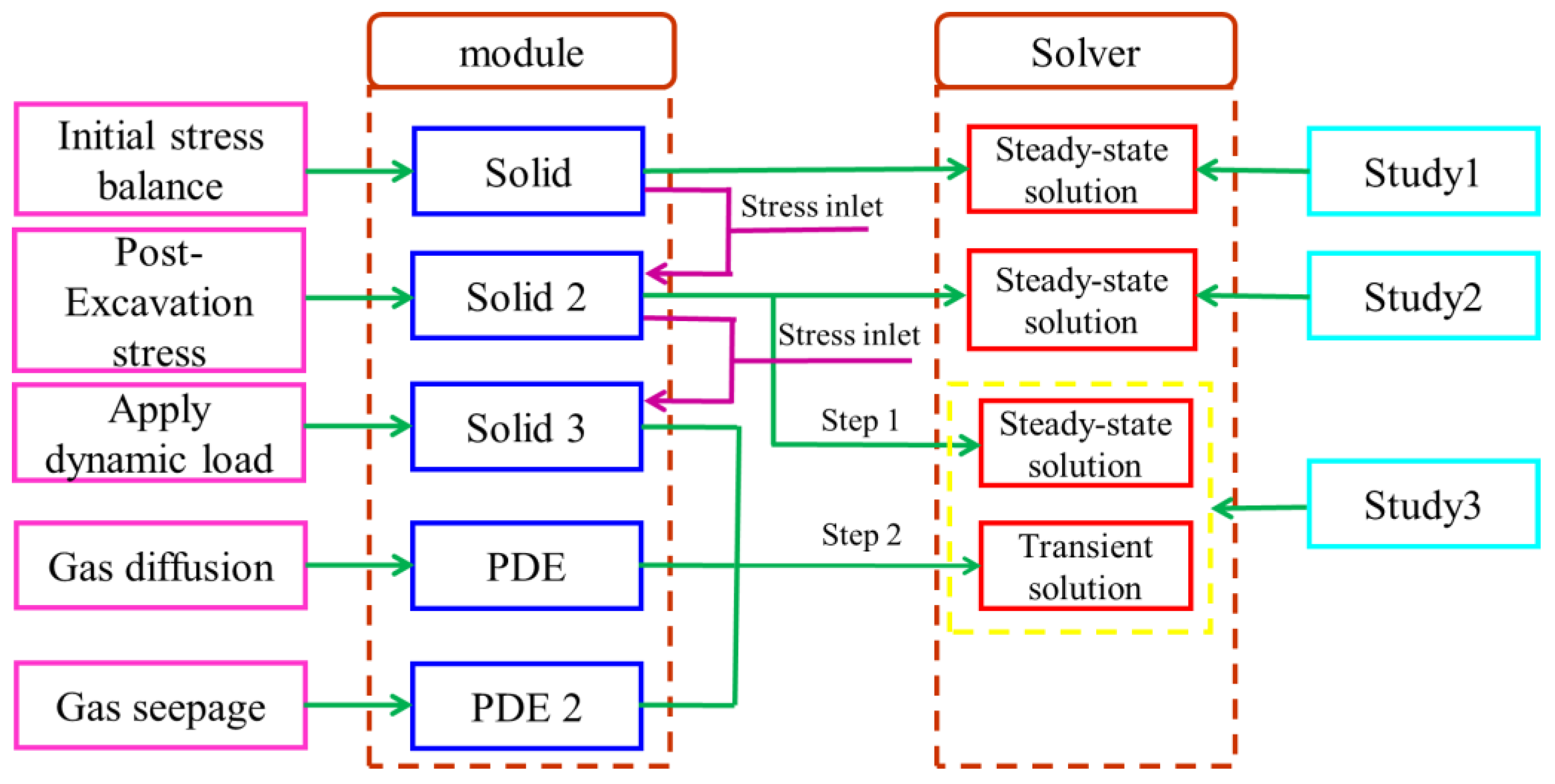
3.3. Mesh Division and Solution Settings
3.4. Initial Parameters
4. Results and Discussion
4.1. Stress Distribution
4.1.1. Stress Distribution of Roadway without Excavation
4.1.2. Stress Distribution after Roadway Excavation
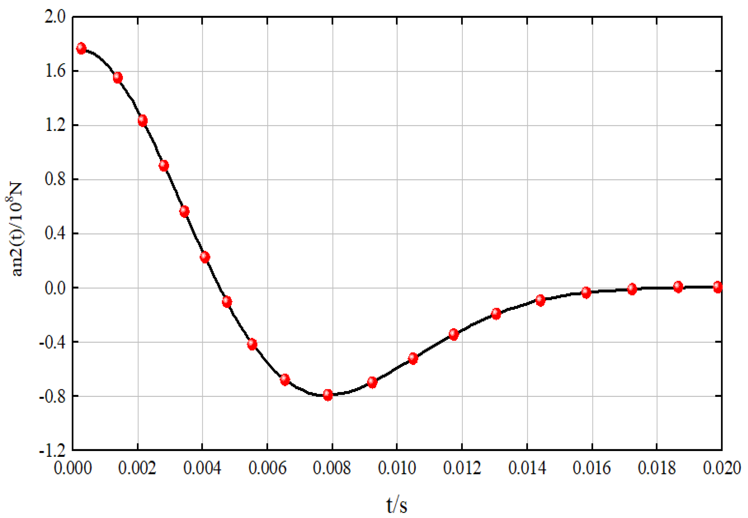
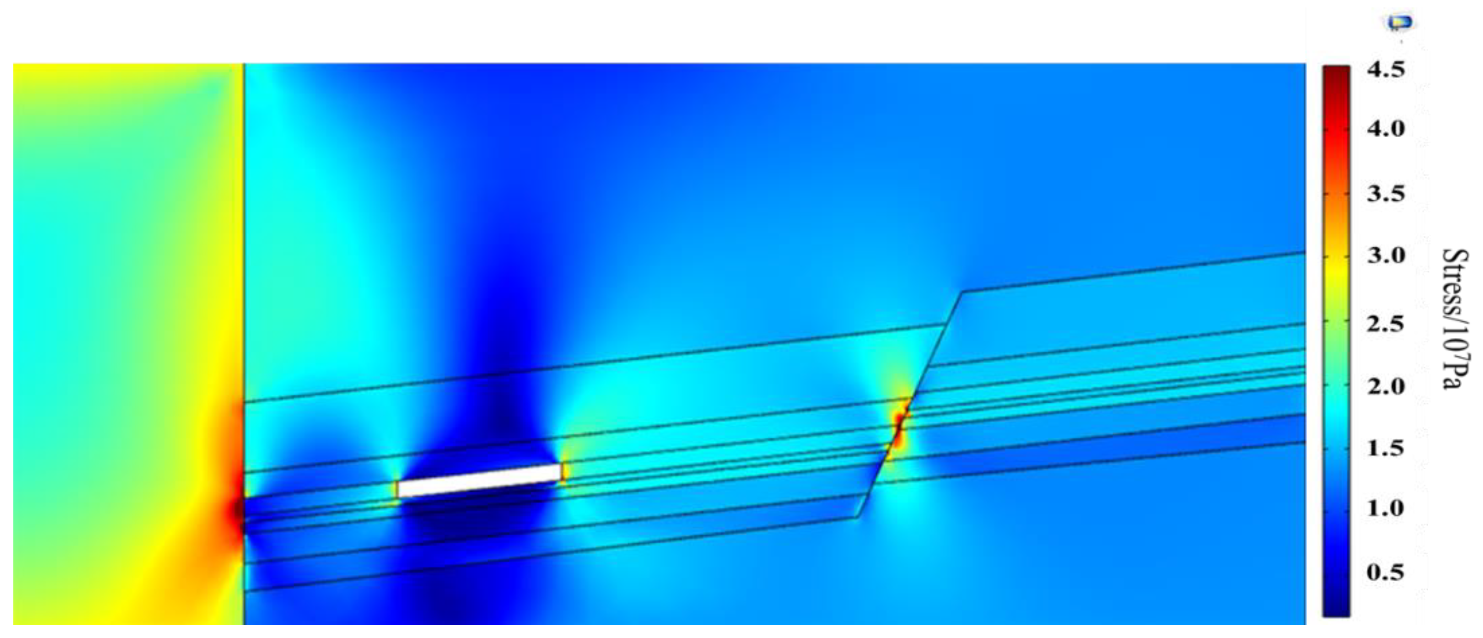
4.1.3. Stress Distribution of Gas-Bearing Coal under Dynamic Load Disturbance
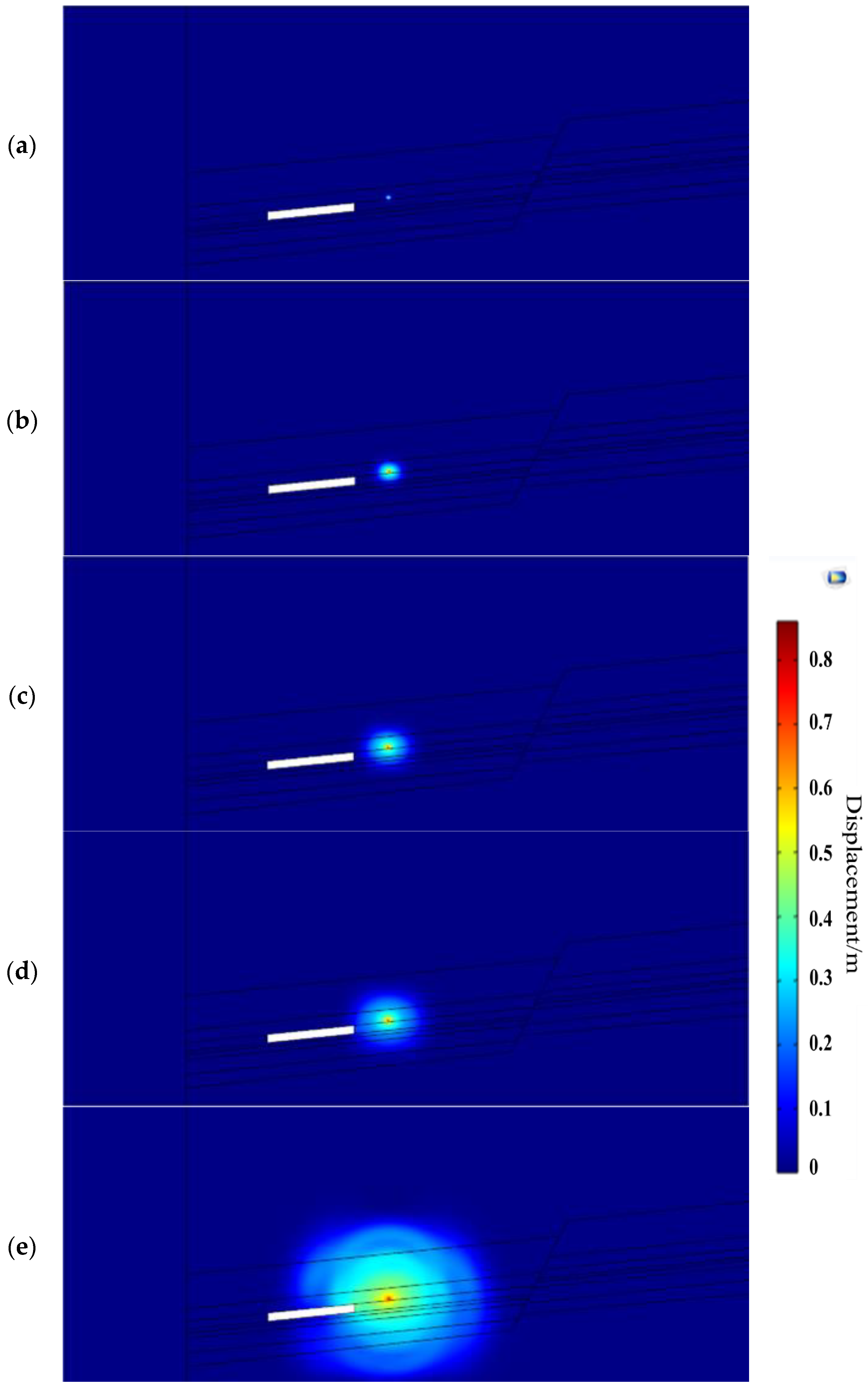
4.2. Displacement Distribution
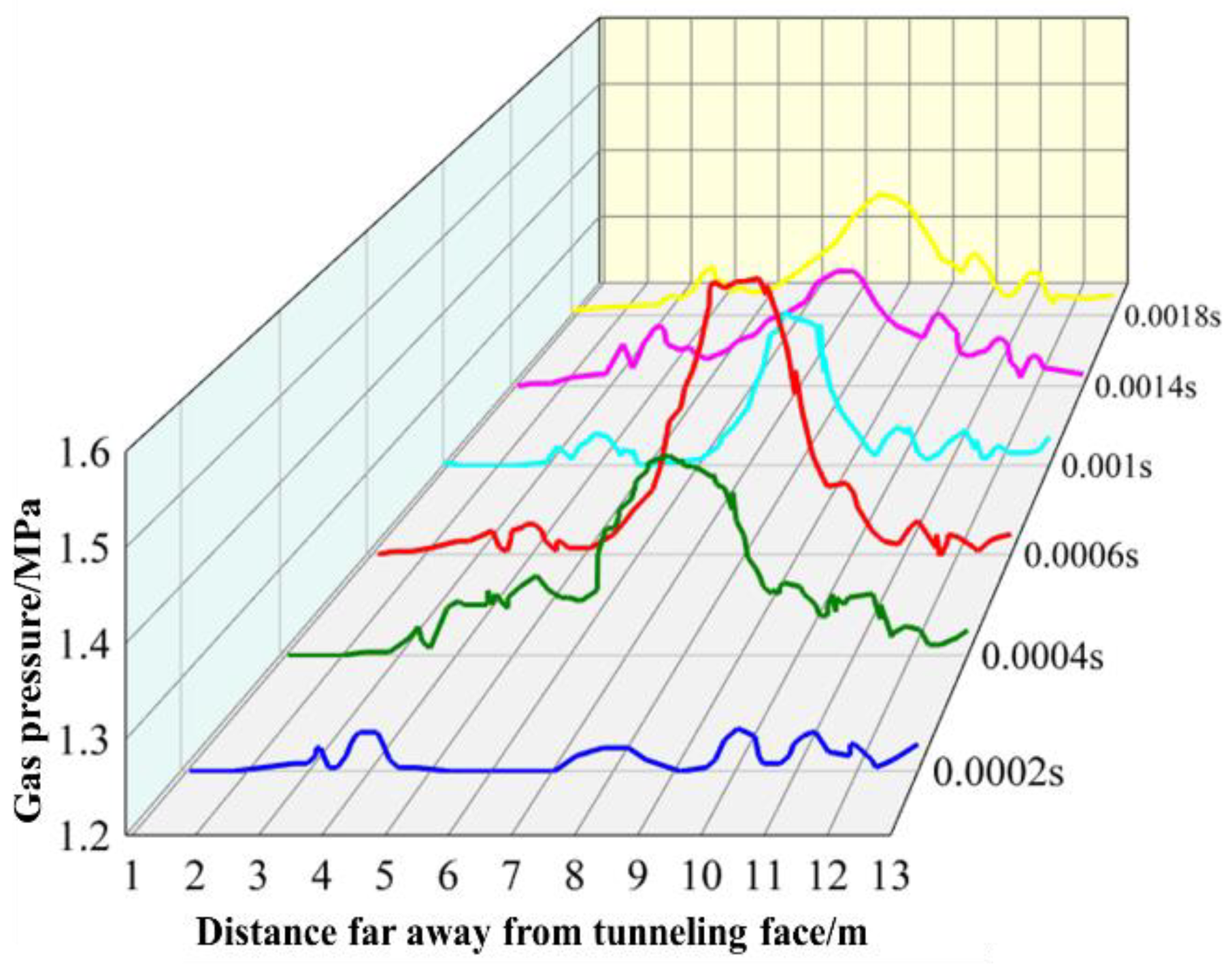
4.3. Gas Migration
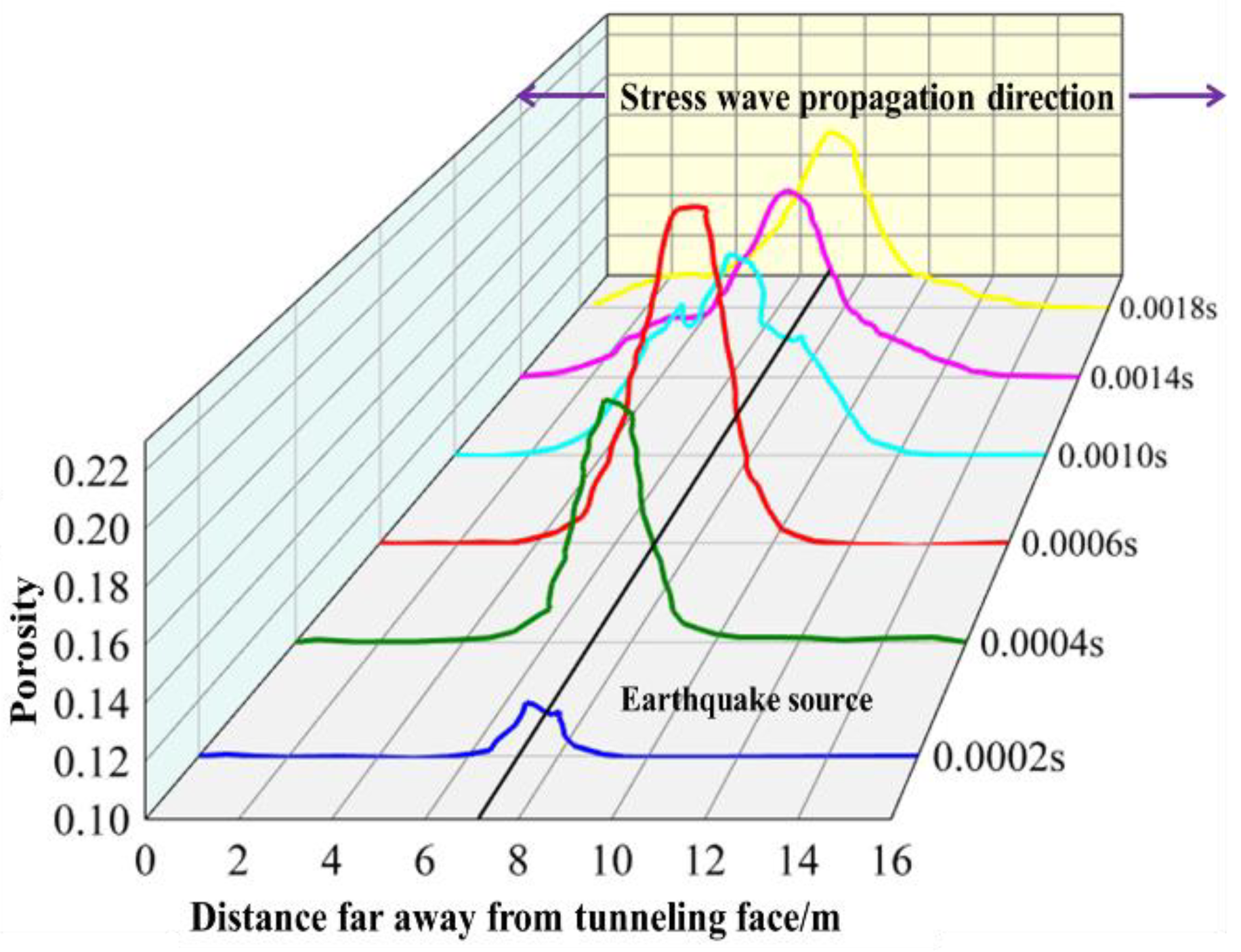
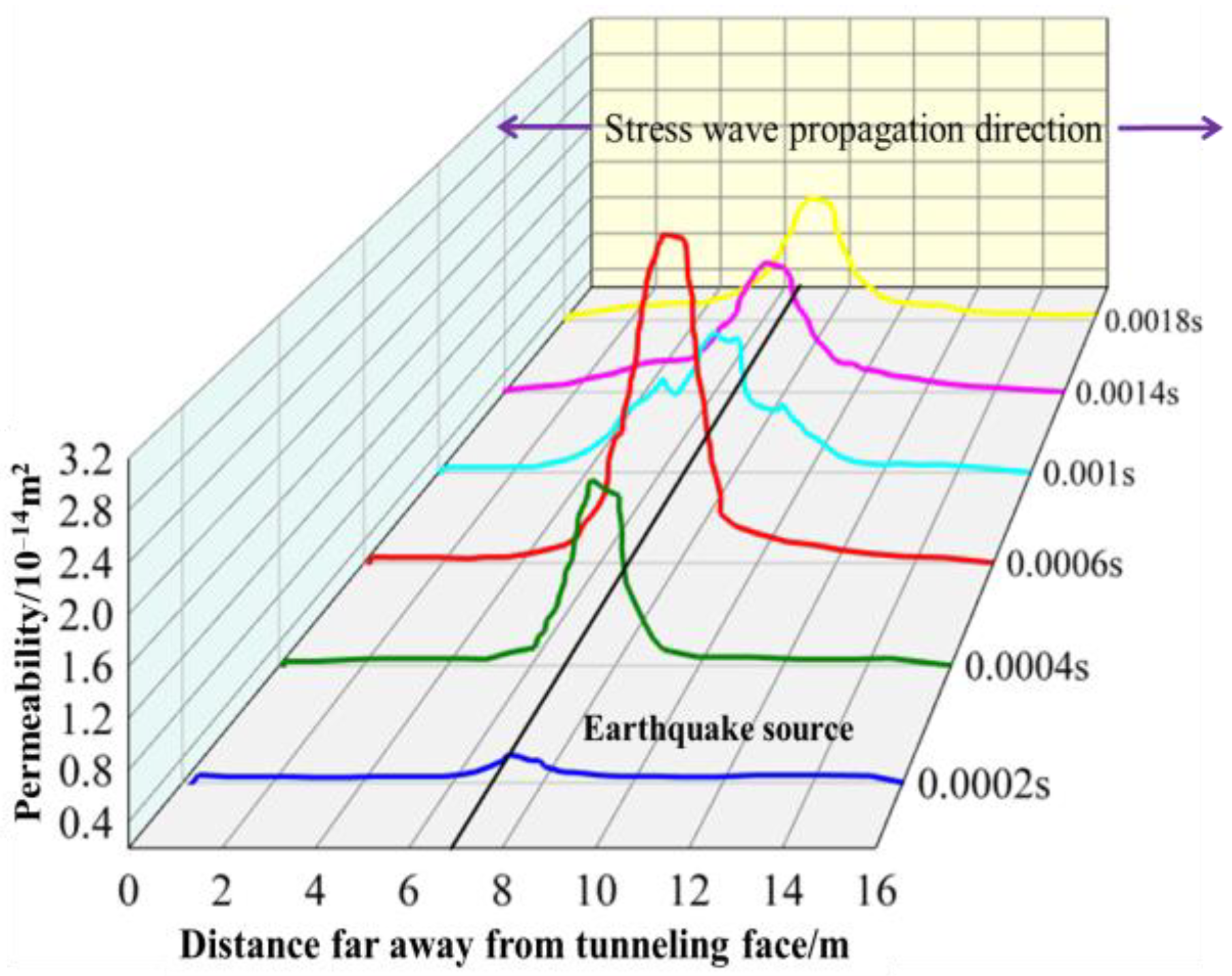
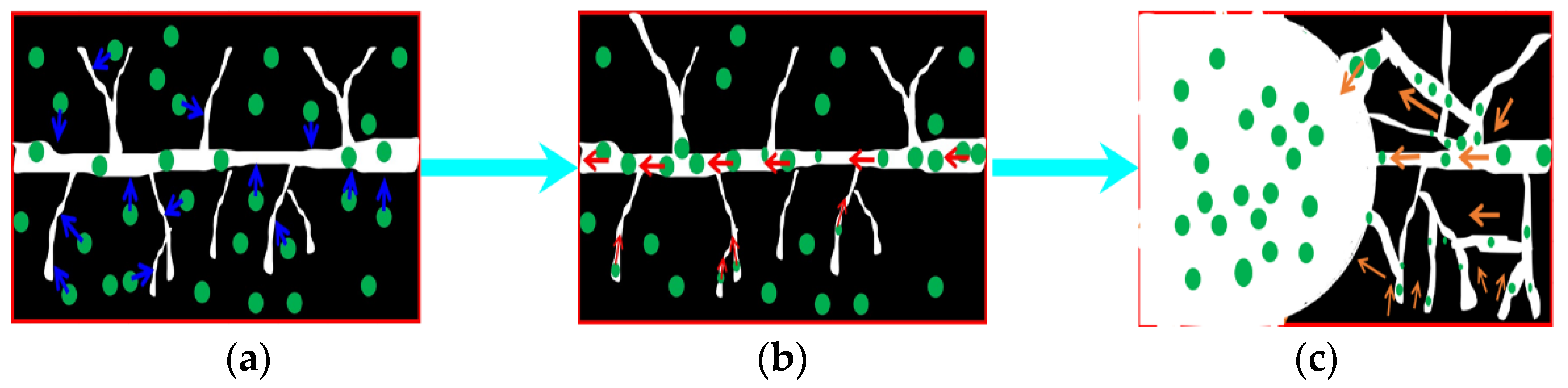
4.4. Coal Seam Porosity and Permeability Evolution
5. Coal and Gas Outburst Case Analysis
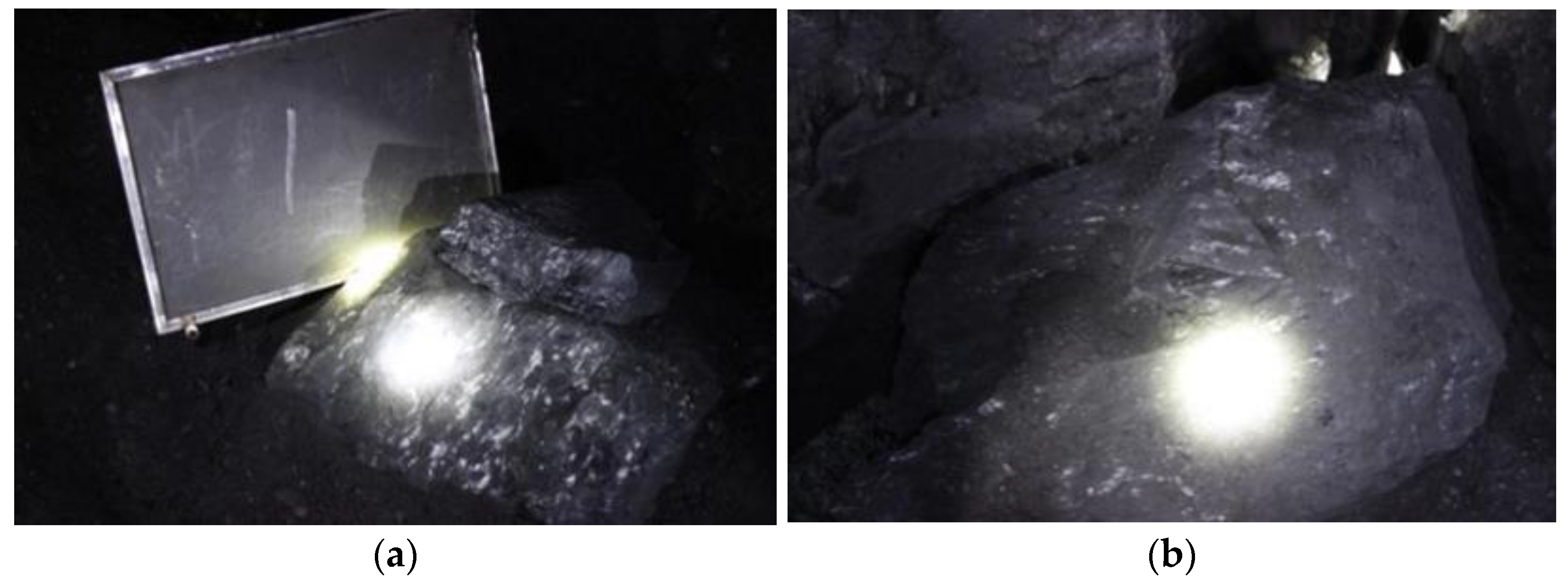
5.1. Coal Outburst in Accident Field
5.2. Gas Migration of Accident Field
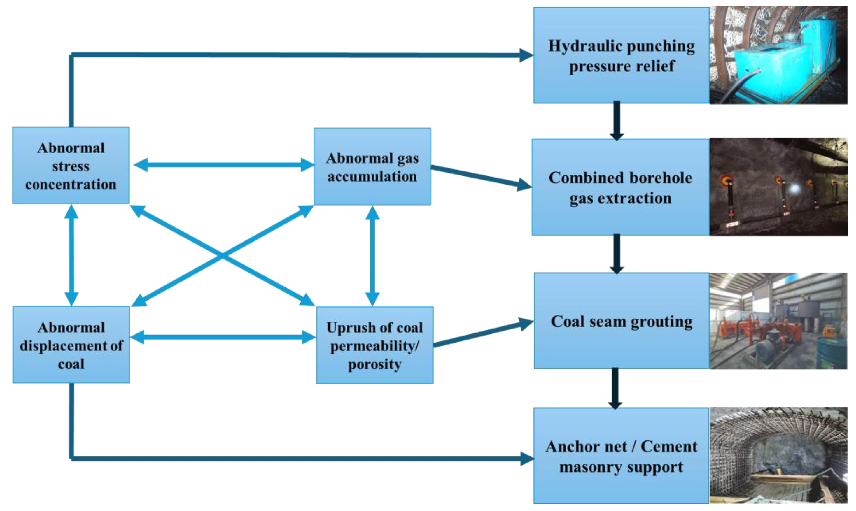
5.3. Mine Safety and Sustainable Development
- (1)
- In order to release the stress in the coal seam in advance, the stress concentration area should be transferred to the deep; to reduce the damage and impact of abnormal ground stress and dynamic loads on the coal body, hydraulic punching should be carried out on the igneous rock wall and fault area before mining to relieve pressure and discharge the coal body. The problem of abnormal gas accumulation caused by complex geological conditions could be solved by increasing the stress concentration range and weakening the stress concentration degree after deep and shallow hole alternate blasting. When the working face starts to advance, advance pressure relief hydraulic punching should be carried out in the excavation head area with the mining progress, so as to ensure the timely release of excavation stress, and avoid greater damage to the coal body caused by the superposition of dynamic stress waves and ground stress.
- (2)
- When the coal seam is impacted by stress waves, a large amount of residual gas in the coal body is released from the coal matrix, leading to serious gas outbursts. In order to reduce the risk of harm from gas outbursts, it is necessary to start from the gas reserves in the coal seams. Before coal seam mining, a combined borehole is used for gas pre-extraction. Gas drainage can greatly reduce gas pressure, lower the internal energy of the gas, and reduce the probability of gas outbursts during abnormal accumulation.
- (3)
- The abnormally increased stress has a destructive effect on the coal body, resulting in a gradual decrease in the porosity and permeability of the coal body from the center of the source to both sides. To enhance the strength and increase the porosity and permeability of the coal body, a grouting measure is adopted to modify the coal body, so that it penetrates the cracks and pores of the coal seam. After solidification, the cracks and pores in the coal seam are filled and sealed to improve the mechanical strength, inhibit gas desorption, and increase the energy required for coal fracture so that the adsorbed gas in the coal seam cannot quickly become free gas, thus preventing the compressed gas potential from turning into outburst kinetic energy when the coal seam is destroyed. Solidifying the bond also improves the strength and changes the physical and mechanical properties of the outburst coal seam, so as to achieve the purpose of preventing coal and gas outbursts.
- (4)
- According to the characteristics of displacement distribution, the migration of coal and rock mass is related to the stress wave propagation distance caused by the main dynamic load. In order to ensure the maximum support strength, the whole roadway should be supported by the anchor net before advancing the working face, and then the focus area of the dynamic load and the position along the stress wave are reinforced by the support method of masonry concrete. In this way, when the impact load is greater than the strength of the coal body, the coal body can still be supported and restrained in the upper part of the roadway, so as to avoid damage to the roadway caused by coal ejection during coal and gas outbursts, which would disrupt the sustainability of coal mine development.
6. Conclusions
- (1)
- The complex geological and deep mining conditions were the main prerequisites for the accident. Before the accident, there was a noticeable vibration sound, indicating the presence of dynamic loads nearby. The complex geological structure and mining activities led to the sliding of the fault ahead, resulting in severe dynamic loads, which directly caused this accident.
- (2)
- The stress propagates outward from the center of the earthquake source, and during the propagation process, the energy continues to decay. Therefore, the displacement of the coal body at the center of the seismic source was maximum, and the displacement of the coal body from the center of the earthquake source to the outside gradually decreased. When the stress propagated to the stress concentration area in front of the coal wall of the excavation head, the superposition of dynamic and static stresses would increase the stress in that area, exceeding the load that the coal body could bear, damaging the coal wall and causing the gas and coal inside to be discharged together into the tunnel.
- (3)
- The dynamic load caused the coal to quickly break, promoted gas desorption, and led to a rapid increase in gas pressure near the seismic source. At the same time, it increased the porosity and permeability of the coal, providing a channel for rapid gas migration. Ultimately, it led to a gas outburst, resulting in the gas backflow phenomenon.
- (4)
- By comparing and analyzing the numerical simulation results with the actual situation on site, a four-in-one, full process coal and gas outburst prevention and control measure is proposed, based on the evolution characteristics of the accident. Through measures of pre-disaster prevention and post-disaster reduction, the probability of accidents in coal mines is reduced while increasing their disaster resistance and providing theoretical support for the sustainability of safety in coal mining production.
Author Contributions
Funding
Institutional Review Board Statement
Informed Consent Statement
Data Availability Statement
Conflicts of Interest
References
- Zhang, W.; Feng, P. Differentiation research of CO2 emissions from energy consumption and their influencing mechanism on the industrial enterprises above designated size in Chinese industrial cities: Based on geographical detector method. Nat. Hazards 2020, 102, 645–658. [Google Scholar] [CrossRef]
- Fauchille, A.; Hedan, S.; Valle, V.; Pret, D.; Cabrera, J.; Cosenza, P. Multi-scale study on the deformation and fracture evolution of clay rock sample subjected to desiccation. Appl. Clay Sci. 2016, 132, 251–260. [Google Scholar] [CrossRef]
- Knapp, M.; Scheidweiler, L.; Külheim, F.; Kleinschek, R.; Necki, J.; Jagoda, P.; Butz, A. Spectrometric imaging of sub-hourly methane emission dynamics from coal mine Ventilation. Environ. Res. Lett. 2023, 18, 4. [Google Scholar] [CrossRef]
- Soleimani, F.; Si, G.; Roshan, H.; Zhang, Z. Numerical modelling of coal and gas outburst initiation using energy balance principles. Fuel 2023, 334, 126687. [Google Scholar] [CrossRef]
- Dutka, B. Effect of depth on the sorption capacity of coals affected by outburst hazard. Fuel 2021, 306, 121611. [Google Scholar] [CrossRef]
- Kursunoglu, N.; Onder, M. Application of structural equation modeling to evaluate coal and gas outbursts. Tunn. Undergr. Space Technol. 2019, 88, 63–72. [Google Scholar] [CrossRef]
- Filippo, M.; Ioannis, S.; Paolo, V.; Victor, M.B. Rocking response of inverted pendulum structures under blast loading. Int. J. Mech. Sci. 2019, 157–158, 833–848. [Google Scholar] [CrossRef]
- Yang, K.; Lei, Y.; Chen, W.; Liu, L. Carbon dioxide emission reduction quota allocation study on Chinese provinces based on two-stage Shapley information entropy model. Nat. Hazards 2018, 91, 321–335. [Google Scholar] [CrossRef]
- Liu, Y.; Zhao, H.; Liu, S.; Sun, W. Asymmetric damage mechanism of floor roadway based on zonal damage characteristics of longwall panel floor: A case study. Nat. Hazards 2022, 114, 1015–1041. [Google Scholar] [CrossRef]
- Wang, C.; Guo, E.; Cao, Y.; Zhang, H.; Zhang, Y. Statistical characteristics of production safety accidents and its strategy implications for administrators in Inner Mongolia. Nat. Hazards 2023, 117, 745–762. [Google Scholar] [CrossRef]
- Bartosz, D.; Renata, K.; Klas, A. Current status of carbon capture, utilization, and storage technologies in the global economy: A survey of technical assessment. Fuel 2023, 342, 127776. [Google Scholar] [CrossRef]
- Danesh, N.; Zhao, Y.; Teng, T.; Masoudian, M.S. Prediction of interactive effects of CBM production, faulting stress regime, and fault in coal reservoir: Numerical simulation. J. Nat. Gas. Sci. Eng. 2022, 99, 104419. [Google Scholar] [CrossRef]
- Yu, M.; Yang, N.; Li, H.; Wang, L.; Wu, M.; Wang, F.; Chu, T.; Wang, K. Numerical investigation on the effects of axial-stress loads on the temperature-programmed oxidation characteristics of loose broken coal. Energy 2024, 289, 129974. [Google Scholar] [CrossRef]
- Zhao, Y.; Lin, B.; Liu, T.; Zheng, Y.; Li, Q.; Song, R. Mechanism of multifield coupling-induced outburst in mining-disturbed coal seam. Fuel 2020, 272, 117716. [Google Scholar] [CrossRef]
- Yang, T.; Xu, T.; Liu, H.; Tang, C.; Shi, B.; Yu, Q. Stress–damage–flow coupling model and its application to pressure relief coal bed methane in deep coal seam. Int. J. Coal Geol. 2011, 864, 357–366. [Google Scholar] [CrossRef]
- Wang, D.; Wei, J.; Qin, H.; Wei, L. Research on Solid-Gas Coupling Dynamic Model for Loaded Coal Containing Gas. Adv. Mat. Res. 2012, 594–597, 446–451. [Google Scholar] [CrossRef]
- Liu, T.; Lin, B.; Yang, W.; Liu, T.; Kong, J.; Huang, Z.; Wang, R.; Zhao, Y. Dynamic diffusion-based multifield coupling model for gas drainage. J. Nat. Gas. Sci. Eng. 2017, 44, 233–249. [Google Scholar] [CrossRef]
- Xue, S.; Wang, Y.; Xie, J.; Wang, G. A coupled approach to simulate initiation of outbursts of coal and gas: Model development. Int. J. Coal Geol. 2011, 862, 222–230. [Google Scholar] [CrossRef]
- Wang, K.; Wang, Y.; Xu, C.; Guo, H.; Xu, Z.; Liu, Y.; Dong, H.; Ju, Y. Modeling of multi-field gas desorption-diffusion in coal: A new insight into the bidisperse model. Energy 2023, 267, 126534. [Google Scholar] [CrossRef]
- Gao, K.; Liu, Z.; Liu, J. Numerical simulation and case analysis of coal and gas outburst in the complex geological structure zone. J. Anhui Univ. Sci. Technol. Nat. Sci. 2016, 365, 5–10. [Google Scholar]
- Li, H.; Lin, B.; Huang, Z.; Teng, F.; Yang, W.; Gao, Y.; Liu, T.; Wang, R. Stress and displacement evolution features of opening seam in mine cross cut based on different in-situ rock stress and orientations. Coal Sci. Technol. 2017, 4510, 88–95. [Google Scholar]
- Zhao, B.; Wen, G.; Nian, J.; Ma, Q.; Fan, C.; Lv, X.; Deng, C. Numerical Simulation Study on the Multi-Physical Field Response to Underground Coal and Gas Outburst under High Geo-Stress Conditions. Minerals 2022, 12, 151. [Google Scholar] [CrossRef]
- Hu, S.; Wang, E.; Kong, X. Damage and deformation control equation for gas-bearing coal and its numerical calculation method. J. Nat. Gas. Sci. Eng. 2015, 25, 166–179. [Google Scholar] [CrossRef]
- Hu, S.; Li, X.; Wang, E. Experimental and Numerical Study on Scale Effects of Gas Emission from Coal Particles. Transp. Porous. Media 2016, 1141, 133–147. [Google Scholar] [CrossRef]
- Hu, S.; Wang, E.; Li, X.; Bai, B. Effects of gas adsorption on mechanical properties and erosion mechanism of coal. J. Nat. Gas. Sci. Eng. 2016, 30, 531–538. [Google Scholar] [CrossRef]
- Liu, A.; Liu, S. A fully-coupled water-vapor flow and rock deformation/damage model for shale and coal: Its application for mine stability evaluation. Int. J. Rock. Mech. Min. 2021, 146, 104880. [Google Scholar] [CrossRef]
- Liu, Z.; Shu, L.; Huo, Z.; Fan, Y. Numerical Study on the Mechanism of Coal and Gas Outburst in the Coal Seam Thickening Area during Mining. Energies 2023, 16, 3288. [Google Scholar] [CrossRef]
- Liu, X.; Zheng, Y.; Hao, Q.; Zhao, R.; Zhang, Z. Rock Damage Model Coupled Stress–Seepage and Its Application in Water Inrush from Faults in Coal Mines. ACS Omega 2022, 7, 13604–13614. [Google Scholar] [CrossRef]
- Shu, L.; Yuan, L.; Li, Q.; Xue, W.; Zhu, N.; Li, Z. Response characteristics of gas pressure under simultaneous static and dynamic load: Implication for coal and gas outburst mechanism. Int. J. Min. Sci. Technol. 2023, 33, 155–171. [Google Scholar] [CrossRef]
- Zhou, A.; Wang, K.; Wang, L.; Du, F.; Li, Z. Numerical simulation for propagation characteristics of shock wave and gas flow induced by outburst intensity. Int. J. Min. Sci. Technol. 2015, 25, 107–112. [Google Scholar] [CrossRef]
- Kong, X.; Li, S.; Wang, E.; Wang, X.; Zhou, Y.; Ji, P.; Shuang, H.; Li, S.; Wei, Z. Experimental and numerical investigations on dynamic mechanical responses and failure process of gas-bearing coal under impact load. Soil. Dyn. Earthquake. Eng. 2021, 142, 106579. [Google Scholar] [CrossRef]
- Wang, E.; Kong, X.; Hu, S.; Li, Z.; Liu, Q. Multi-scale Fractured Coal Gas–Solid Coupling Model and Its Applications in Engineering Projects. Transport. Porous. Med. 2018, 121, 703–724. [Google Scholar] [CrossRef]
- Tao, Y.; Xu, J.; Cheng, M.; Li, S.; Peng, S. Theoretical analysis and experimental study on permeability of gas bearing coal. Chin. J. Rock. Mech. Eng. 2009, 282, 3363–3370. [Google Scholar]
- Li, P.; Kong, X.; Lu, D. Mathematical modeling of flow in saturated porous media on account of fluid-structure coupling effect. J. Hydrodyn. 2003, 184, 419–426. [Google Scholar]
- Liu, J.; Chen, Z.; Derek, E.; Qu, H.; Chen, D. Interactions of multiple processes during CBM extraction: Acritical review. Int. J. Coal. Geol. 2011, 87, 175–189. [Google Scholar] [CrossRef]
- Liu, J.; Elsworth, D. Evaluation of pore water pressure fluctuation around an advancing long wall panel. Adv. Water. Res. 1999, 226, 633–644. [Google Scholar] [CrossRef]
- Wyss, M.; Brune, J.N. Seismic moment, stress, and source dimensions for earthquakes in the California-Nevada region. J. Geophys. Res. 1968, 73, 4681–4694. [Google Scholar] [CrossRef]
- Hanks, T.C.; Kanamori, H. A moment magnitude scale. J. Geophys. Res. 1979, 84, 2348–2350. [Google Scholar] [CrossRef]
- Gutenberg, B.; Richter, C.F. Seismicity of the earth Geol. Soc. Am. Spec. Pap. 1941, 34, 1–33. [Google Scholar] [CrossRef]
- Wang, C.; Cheng, Y. Role of coal deformation energy in coal and gas outburst: A review. Fuel 2023, 332, 126019. [Google Scholar] [CrossRef]
- Ma, Y.; Nie, B.; He, X.; Li, X.; Meng, J.; Song, D. Mechanism investigation on coal and gas outburst: An overview. Int. J. Miner. Metall. Mater. 2020, 27, 872–887. [Google Scholar] [CrossRef]
- Zhang, G.; Wang, E. Risk identification for coal and gas outburst in underground coal mines: A critical review and future directions. J. Nat. Gas. Sci. Eng. 2023, 118, 205106. [Google Scholar] [CrossRef]


| Name | Rock Character | Elastic Modulus (GPa) | Poisson’s Ratio | Density (kg/m3) | Cohesive Force (MPa) | Angle of Internal Friction (deg) |
|---|---|---|---|---|---|---|
| Main roof I | Medium white siltstone | 9.50 | 0.25 | 2700 | 12.3 | 29 |
| Direct roof of coal I | Grey black siltstone | 7.80 | 0.23 | 2600 | 10.5 | 27 |
| Coal seam I | Coal | 1.20 | 0.20 | 1500 | 2.0 | 30 |
| Coal floor I | Grey black siltstone | 7.80 | 0.23 | 2600 | 10.5 | 27 |
| Coal II | Coal | 1.20 | 0.20 | 1500 | 2.0 | 30 |
| Coal direct bottom II | Grey brown fine medium sandstone | 11.30 | 0.28 | 2717 | 17.0 | 25 |
| Hard floor II | Black sand shale | 26.00 | 0.33 | 2700 | 27.2 | 28 |
| Igneous wall | Igneous rock | 28.00 | 0.17 | 2800 | 12.6 | 39 |
| Other rock mass | Medium sandstone | 13.00 | 0.30 | 2717 | 19.0 | 25 |
| Parameter | Value | Parameter | Value |
|---|---|---|---|
| Initial porosity of coal I sample, Φ01 | 0.3 | Limit adsorption capacity, VL | 0.02 |
| Initial permeability of coal I sample, k01 | 2.5 × 10⁻¹⁵ m2 | Methane Langmuir adsorption pressure constant, PL | 1 |
| Initial porosity of coal II sample, Φ02 | 0.3 | The molar volume constant of gas in standard state, VM | 22.4 L/mol |
| Initial permeability of coal II sample, k02 | 2.5 × 10⁻¹⁵ m2 | The density of gas in standard state, ρgs | 0.717 m3/kg |
| Initial porosity of rock mass, Φ0r | 0.01 | The molecular weight of methane, Mg | 16 g/mol |
| Initial permeability of rock mass, k0r | 3 × 10⁻²⁰ m2 | Universal gas constant, r | 8.314 J/(mol/K) |
| Initial gas pressure of coal matrix, Pm0 | 1.20 MPa | Simulated field temperature, T | 293.1 K |
| Initial gas pressure of coal fissure, Pf0 | 1.20 MPa | Dynamic viscosity of gas molecules, μ | 1.84 × 10⁻⁵ Pa·s |
| Gas pressure in rock, Pr0 | 0.10 MPa | Muir volume strain constant, εL | 0.012 |
| Muir volume constant, b1 | 1.84 × 10⁻³ | Muir pressure constant, b2 | 1/16 × 10−171/Pa |
Disclaimer/Publisher’s Note: The statements, opinions and data contained in all publications are solely those of the individual author(s) and contributor(s) and not of MDPI and/or the editor(s). MDPI and/or the editor(s) disclaim responsibility for any injury to people or property resulting from any ideas, methods, instructions or products referred to in the content. |
© 2024 by the authors. Licensee MDPI, Basel, Switzerland. This article is an open access article distributed under the terms and conditions of the Creative Commons Attribution (CC BY) license (https://creativecommons.org/licenses/by/4.0/).
Share and Cite
Kong, X.; Zhao, T.; Cai, Y.; He, D. Numerical Multifield Coupling Model of Stress Evolution and Gas Migration: Application of Disaster Prediction and Mining Sustainability Development. Sustainability 2024, 16, 3667. https://doi.org/10.3390/su16093667
Kong X, Zhao T, Cai Y, He D. Numerical Multifield Coupling Model of Stress Evolution and Gas Migration: Application of Disaster Prediction and Mining Sustainability Development. Sustainability. 2024; 16(9):3667. https://doi.org/10.3390/su16093667
Chicago/Turabian StyleKong, Xiangguo, Tianshuo Zhao, Yuchu Cai, and Di He. 2024. "Numerical Multifield Coupling Model of Stress Evolution and Gas Migration: Application of Disaster Prediction and Mining Sustainability Development" Sustainability 16, no. 9: 3667. https://doi.org/10.3390/su16093667