
Compatibility of Sustainable Facility Management and Building Information Modeling Applications: The Role of Naming Conventions

Department of Civil & Environmental Engineering, Rowan University, 201 Mullica Hill Rd., Glassboro, NJ 08021, USA
*
Author to whom correspondence should be addressed.
Sustainability 2023, 15(2), 1482; https://doi.org/10.3390/su15021482
Submission received: 16 December 2022
/
Revised: 7 January 2023
/
Accepted: 9 January 2023
/
Published: 12 January 2023
(This article belongs to the Special Issue Inclusive Design and Energy Efficiency in Sustainable Built Environment)
Abstract
:This research focuses on data transfer from Sustainable Facility Management (SFM) to Building Information Modeling (BIM) applications—specifically BUILDER SMS to Autodesk Revit—where the BIM models are created for existing buildings. BIM models were created for ten existing buildings to support initial data transfer based on different object parameters: (a) alphanumeric identifier (five buildings); and (b) name (five buildings). The identifier is randomly assigned by BUILDER SMS. The name is derived from the cardinal direction for exterior components and room names for interior components. The comparison of the methods was accomplished by observing times to ensure data compatibility, complete Revit models, and transfer data from BUILDER SMS to Revit. The name method was faster regarding data compatibility, but no statistical evaluation could be made. The identifier method resulted in shorter model completion times, but the difference was not statistically significant. It was also faster for first-time data transfer, but, again, no statistical evaluation could be made. The difference in total effort required by the methods was not large. Furthermore, the first data transfer for either method can transfer the other parameter, i.e., a name-based data transfer can add the identifier to the Revit model and an identifier-based transfer can add the name. The name method may be slightly better than the identifier method because object names follow an intuitive and logical standard naming convention (specified in the SFM application). The process of ensuring data compatibility by manually entering object names may be less error-prone compared to manually entering alphanumeric identifiers; however, that was not demonstrated here as all of the resulting models were error-free regarding data transfer. The methods described provide useful insights for other SFM/BIM transfer scenarios, such as other applications and models generated during the design phase.
1. Introduction
The management of buildings has compelling environmental and economic drivers. Buildings account for over 40% of all energy use in the United States and a similar percentage of greenhouse gas emissions [1,2]. Building operating costs are five to seven times that of initial investment [3].
Facility management (FM) has the goal of maintaining a built environment’s functionality, comfort, safety, and efficiency during operation [4,5]. Sustainable facility management (SFM) further strives to reduce the negative impact of buildings on their occupants and the environment [6]. The US military uses the BUILDER Sustainable Management System (BUILDER SMS, https://www.sms.erdc.dren.mil, accessed on 8 January 2023). It is the SFM database application studied in this research.
Building Information Modeling (BIM) offers tools for more effective building and infrastructure planning, design, construction, and management [7]. Models often include 3D computer-generated representations of building envelopes and interiors that also include mechanical, electrical, and plumbing objects. BIM can also incorporate data, e.g., material descriptions, model numbers, and URLs pointing to documents such as equipment manuals or maintenance plans. Autodesk Revit (www.autodesk.com/products/revit/, accessed on 8 January 2023) is the BIM application studied in this research.
Transferring BUILDER SMS information into Revit allows one to combine the visual advantages of Revit with the SFM information found in BUILDER SMS. The purpose of this study is to evaluate an alternative to the data transfer method developed by Loeh et al. [8]. In that study—conducted with the second and third authors of this article—point cloud data, Autodesk Recap, and Autodesk Revit were used to create Revit models of existing structures. Facility data were collected and entered into BUILDER SMS. BUILDER SMS and Revit contained the same objects for each building but were not directly compatible regarding data transfer. To make the two sets of data compatible, ID numbers automatically generated in BUILDER SMS were manually entered into Revit for each object of interest. This occurred after model creation.
In the study described here, Revit models were created using object names already specified in BUILDER SMS. This approach supports data transfer based on object name, rather than an identifier. The two methods are compared using case studies of the creation of ten Revit models, nine new buildings plus the building from Loeh et al. [8]. The research question tested by this research is as follows. The name-based transfer method will produce models with less effort as it will be easier to find and correct errors in object names compared to random alphanumeric identifiers.
2. Background
2.1. Benefits of FM/SFM and BIM
FM/SFM is used to maintain a built environment’s functionality, comfort, safety, and efficiency during operation [5,9]. Operation is the longest period in the lifecycle of a building and where most expenditures accumulate [3,10,11]. Maintaining reliable records is a challenging aspect of FM/SFM and applications abound to assist. BUILDER SMS is a U.S. Department of Defense (DoD)-mandated SFM platform. Its use is required in all major branches of the U.S. military, as well as other U.S. government agencies [12]. The U.S. Army alone operates and maintains over 165,000 buildings [13]. BUILDER SMS contains a wealth of information, including inventory, condition assessments, work plans, scenarios, forecasting, functionality assessments, and reports. The effective use of BUILDER SMS can have a significant impact on energy use and greenhouse gas emissions in the U.S. BUILDER SMS was the focus of Loeh et al. [8], but no other studies of BUILDER SMS have been identified in scholarly literature. BUILDER SMS version 3.6.6 is the focus here.
BIM has been used for over 20 years [14]. BIM results in 3D representations of buildings and interconnected databases of organized, internally consistent, and computable information [15]. BIM applications can contain a large amount of building/project data, including material quantities, installation dates, subcontractor obligations, the type of material used in a facility, costs, and schedules. A BIM application can simplify a project’s data collection and storage processes because it is a single source for all project data [16]. During design and construction and over the life of a building, large amounts of data are generated; maintaining this data can result in greater efficiencies, such as providing accurate as-built information to reduce the cost and time needed for renovations, increasing customer satisfaction, and optimizing the operation and maintenance of the building systems to reduce energy use.
The ultimate objective of using BIM for SFM is to facilitate the use of data over the facility life cycle to provide safe, healthy, effective, and productive working environments [17]. BIM allows for the management of life cycle data in a visual environment. According to Chong et al., real-time FM-enabled BIM systems can improve existing building sustainability by reducing inefficiencies [18]. BIM can be used to perform FM activities such as commissioning and closeout, retro-commissioning, warranty, and service information maintenance, quality control, energy and space management, planning and performing maintenance, emergency management, retrofit planning, and deconstruction [19,20,21,22,23]. One of the most effective ways to reduce carbon emissions is by renovating existing buildings to reduce energy consumption [18]. BIM can aid in renovating existing buildings by providing up-to-date plans and dimensions [23].
Autodesk Revit is a popular BIM authoring software. It has been a subject of previous research, e.g., [8,24,25,26,27]. Autodesk Revit allows architects and building professionals to design and document a building by creating a parametric three-dimensional model that includes geometry and non-geometric design and construction information [28]. Revit 2022 is the BIM software studied in this research.
2.2. BUILDER SMS and Revit Data Transfer
Data can be transferred between SFM and BIM applications to take advantage of BIM’s advanced visualization and analysis capabilities [20]. While numerous studies have investigated the handoff of data between SFM and BIM [8,15,20,29,30,31], only one article was identified that specifically investigated the handoff of data between BUILDER SMS and BIM [8]. Data transfer between specific platforms must be considered, as platform-specific details inform at least three of the main challenges identified by Tsay, et al. [29]: limited interoperability, unclear BIM requirements for FM at early stages, and impact on current processes. As BUILDER SMS is the U.S. DoD-mandated SFM platform, it is especially important to consider the requirements for BUILDER SMS to BIM data handoff. The DoD operates many existing facilities that have yet to be actualized in a BIM application. As models are created for these facilities, the opportunities associated with transferring BUILDER SMS information into BIM grow. It is important to consider transfer protocols now, before modeling these existing buildings.
Objects in BUILDER SMS are grouped into categories [32]. An example of a category is the exterior enclosure. A category is further subdivided into components. Components of the exterior enclosure category include exterior walls, windows, and doors. A particular component is identified as a section. Objects in a Revit model are organized into three families: system, loadable, and in-place [33]. System family elements are predefined in Revit, such as walls, roofs, floors, ducts, and pipes. Loadable family elements can be loaded into Revit and edited by the user, for example, windows, doors, fixtures, and furniture. In-place families are unique elements created by the user within a specific Revit project. BUILDER SMS components and sections are equivalent to Revit families and elements. In this article, the generic term ‘object’ is used to mean sections (BUILDER SMS) and elements (Revit). Data transfer between BUILDER SMS and Revit means transferring information associated with the objects of a specific building.
BUILDER SMS data can be exported as a Builder Remote Entry Database (BRED) file which is compatible with Microsoft Access and Excel. Autodesk Revit uses third-party plugins to export database files into various file formats, including Microsoft Access and Excel. Any common parameter with unique values can be used to transfer information from BUILDER SMS to Revit. This process can be automated. That was not investigated in this research as our primary focus was creating data-compatible models.
Loeh et al. [8] used the BUILDER SMS parameter “SEC_ID” to transfer data to Revit. BUILDER SMS generates the unique alphanumeric identifier, SEC_ID, for each building object. Once SEC_IDs are manually added to relevant Revit objects, data transfer can be accomplished quickly for a given building. The Loeh workflow is given in Figure 1.
BUILDER SMS assigns object names using the parameter SEC_NAME. SEC_NAMEs are entered into the BUILDER SMS database after a building inventory. Each SEC_NAME is derived from the cardinal direction for exterior components and room names for interior components [32]. SEC_NAME is organized using UNIFORMAT II categories [34]. The method introduced here modifies the Loeh method by integrating BUILDER SMS SEC_NAMEs into Revit models during model creation using building-specific REVIT templates. The SEC_NAME parameter is then used to transfer data between BUILDER SMS and Revit; thus, avoiding the manual entry of SEC_IDs. Each UNIFORMAT II category is imported/exported separately to avoid SEC_NAME conflicts. The first data transfer accomplishes the transfer of SEC_IDs; thus, future data transfers for a given building can be accomplished using SEC_ID, all UNIFORMAT II categories at once. Table 1 is used to contrast the steps of the two methods.
3. Methodology
The New Jersey Department of Military and Veterans Affairs (NJDMAVA) was the study sponsor. The research was conducted at the Sustainable Facility Center (SFC) at Rowan University. SFC faculty, staff, and graduate students supervise undergraduates enrolled in a two-semester project-based course (Fall and Spring semesters) where they create Revit models of NJDMAVA buildings. Each student works at least 5.5 h a week for 30 weeks to create a Revit model of one building. Summer interns work with SFC staff to inventory NJDMAVA buildings to complete the BUILDER SMS database for NJDAMVA buildings. Buildings used here were scheduled to be modeled or inventoried via a process independent of this research.
3.1. Loeh and Proposed Methods
The creation of Revit models in the SFC starts with 3D scans. Scans are imported into Autodesk Recap and stitched/indexed to create a 3D point cloud. The 3D point cloud is imported into Autodesk Revit and traced to create a 3D building model: first, the building envelope; then, the interior and, finally, any desired mechanical, electrical, and/or plumbing (MEP) systems. Model creators keep daily logs that were used to determine when two modeling milestones were reached: completion of the building envelope and completion of the building interior. Example progress logs are given in the Supplemental Materials.
At this point, the Revit model does not include BUILDER SMS data. That is accomplished using the Loeh or proposed data transfer methods. The Loeh method is summarized in Figure 1 and Table 1 and described in detail in Loeh et al. [8]. Data compatibility is based on the SEC_ID parameter. A summary of the proposed method is given in Table 1 and Figure 2 and is described in detail below. Data compatibility is based on the BUILDER SMS SEC_NAME parameter.
In the proposed method, a master Revit template is created for the typical building, in this case, the typical NJDMAVA building. Two BUILDER SMS parameter groups are included: Component Section and Section Details. The master file is duplicated and modified to create a building-specific Revit template for each building to be modeled in Revit. It contains all objects for which data transfer is anticipated, with their BUILDER SMS names. Standard operating procedures (SOP) for creating master and building-specific Revit templates are given in the Supplemental Materials.
BUILDER SMS naming convention examples are given in Table 2. Examples of exterior wall names used in BUILDER SMS for an NJDMAVA building are shown in Figure 3. The colors mark the names and their related exterior walls. BUILDER SMS naming follows UNIFORMAT II classifications.
Components are divided into sections when a significant variation exists in material/equipment category, age, or construction history, which impacts the life cycle characteristics of the component. All exterior components (enclosure, windows, doors, etc.) are required to be sectioned in a cardinal direction. Additions, new wings, or major renovations require identifying separate exterior enclosure sections with a different age identified in the section name. For instance, two metal panel sections could have the names ‘NORTH—1970’ and ‘NORTH—2015’. If a building has windows on all four sides, there will be North/South/East/West window section names. The section name for a window component consists of 3 parts (in this order): (1) Cardinal direction, (2) Material type (Wood, Steel, Aluminum, Vinyl), and (3) Window opening count, e.g., ‘NORTH-ALUMINUM-20’. If there are multiple install dates of the same window type, the section name would include the install year, e.g., ‘NORTH- ALUMINUM-10-1970’ and ‘NORTH-ALUMINUM-10-2015’. When sectioning by cardinal direction, one includes all components on the predominant side of the section. For example, if the north face of a building has an indent with a window that is technically facing east, it is included in the north-facing quantity. Doors should be sectioned in a cardinal direction in the same manner as other exterior components.
Interior construction is always sectioned by floor. If there are multiple easily definable wings of a building with different install dates, then sectioning by floor and by wing is required. For example, if there is an east and west wing on a 2-floor building, one would use ‘FL2—EAST’ and ‘FL2—WEST’. In the case where age/condition/material type is different for a single component type it is required that the functional area be included in the section name such as ‘FL1—LOBBY’, ‘FL1—RM 109′, and ‘FL2—KITCHEN’.
Equipment components are always sectioned by the floor. Typical section names used to describe equipment components may be used where a unique component exists such as PUMP-1, BOILER-1, etc. If the building has more than one of a particular type of component, one must separate component sections, e.g., in a building with 5000 and 10,000 CFM air handlers. When an equipment tag is included in the section name, it should match exactly what was found in the field. For example, if the boiler ID number is B-1, the section name equipment tag portion should read B-1. If the boiler is tagged B1, the equipment tag portion should read B1.
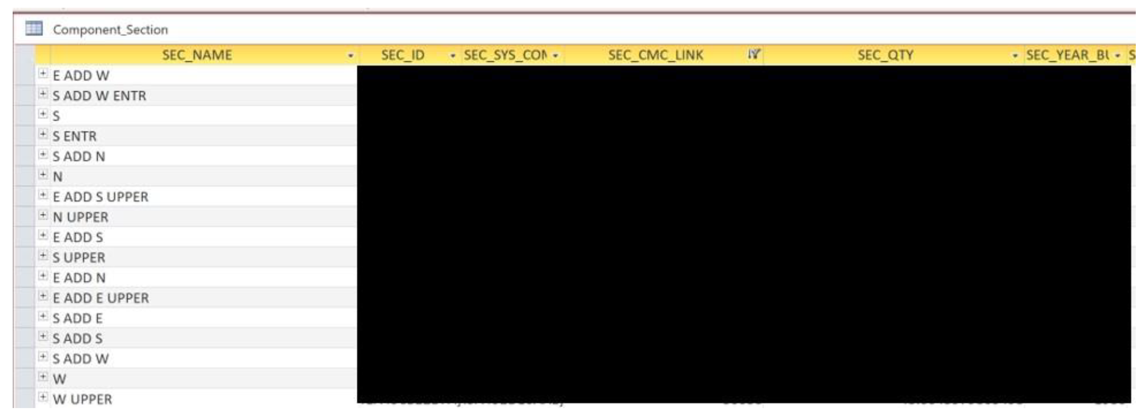
Data transfer from BUILDER SMS to Revit is accomplished by opening a building’s BUILDER SMS BRED file in Microsoft Access. The Microsoft Access select query for Component Section and Section Details are exported to a Microsoft Excel spreadsheet. An example Component Section query is shown in Figure 4. Some information is redacted throughout this article, due to the security policies of the sponsor [35].
Diroots SheetLink (https://diroots.com, accessed on 8 January 2023) is used to export data from Revit to a second Excel spreadsheet. The two excel files, one from BUILDER SMS and one from Revit, are combined into a third Excel spreadsheet using the Excel Power Query command. Power Query combines spreadsheets by matching column data. The data in the combined spreadsheet are then imported back into Revit using Diroots SheetLink. The SOP for data transfer is given in the Supplemental Materials.
3.2. Method Comparisons
The comparison of the methods was accomplished by observing and timing: (a) data compatibility efforts, (b) Revit model creation, and (c) first-time data transfer. The ten buildings used to accomplish these comparisons are described in the next section. The effort required to ensure Revit/BUILDER SMS data compatibility was evaluated by comparing the time to manually input SEC_IDs into Revit models after creation (Loeh method—1 building) to the time to create building-specific Revit templates with SEC_NAMEs (proposed method—five buildings). The effort to complete the Revit models was evaluated by comparing the weeks to reach two modeling milestones, four buildings for each method. Progress logs were used to determine the time to reach each milestone. T-Tests were used to determine if the milestone times differed in a statistically significant way. The time to transfer data from BUILDER SMS to Revit was evaluated by comparing the first-time transfer using each method (Loeh method—1 building; proposed method—5 buildings). All tasks were completed by a single person; thus, times reported here are equivalent to person-time, i.e., person-minutes or person weeks.
3.3. Case Study Buildings
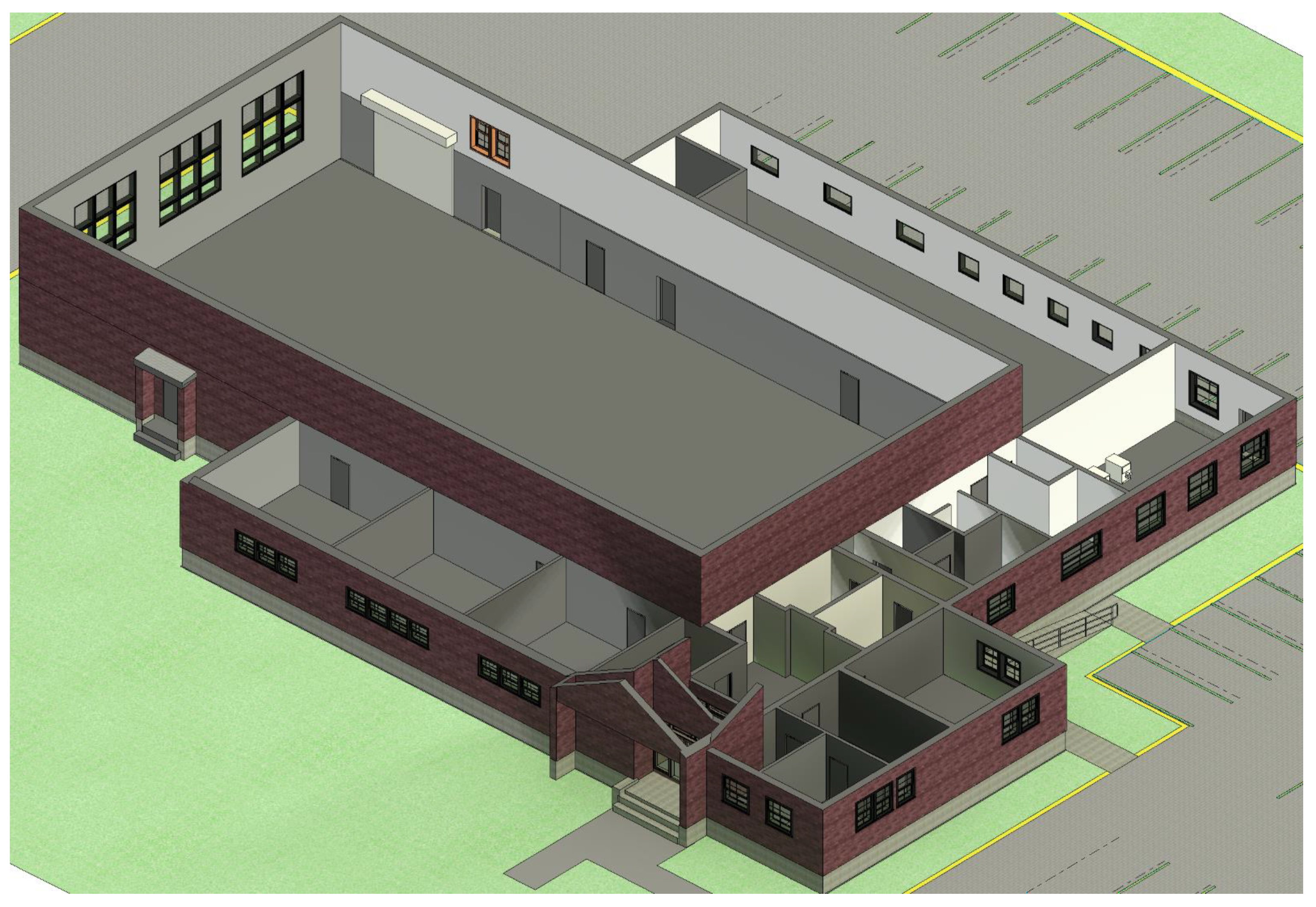
Ten buildings were modeled (Revit) and/or inventoried (BUILDER SMS) for this research, including one scanned in 2016 (the building used by Loeh et al. [8]), one scanned in 2019 (proposed method), four scanned in 2020 (Loeh method), and another four scanned in 2021 (proposed method). The buildings are described in Table 3. An example Revit model is shown in Figure 5. Building identities are not revealed, as per the sponsor’s security requirements [35]. Except where noted below, each building consisted of a drill floor, offices, kitchen and cafeteria, storage rooms, bathrooms, and mechanical room.
L-16-5 is the building used in Loeh et al. [8]. F-19-9 was chosen for study because it is similar to the Loeh building in floor area, types of rooms, and number of UNIFORMAT II categories in its Revit model. The nine UNIFORMAT II categories are B10 Superstructure, B20 Exterior Enclosure, C10 Interior Construction, C20 Stairs, C30 Interior Finishes, D20 Plumbing, D30 HVAC, D40 Fire Protection, and D50 Electrical. The 2020–21 and 2021–22 Revit models include five UNIFORMAT II categories: A10 Foundations; B10 Superstructure; B20 Exterior Enclosure; B30 Roofing; and D30 HVAC.
Four Revit models were created by students during the 2020–21 academic year following the Loeh method. The students were responsible for assigning names to building objects in the Revit models. No attempt was made to follow a standard naming convention; rather, names were based on floorplans provided by NJDMAVA. Once models are developed this way, the easiest way to transfer BUILDER SMS data is via the Loeh method. The use of the proposed method would require modifying object names to conform to the BUILDER SMS database for the given building.
Four more Revit models were created by students during the 2021–22 academic year. These students were given a building-specific Revit template that contained appropriate SEC_NAMEs for their building obtained from BUILDER SMS; thus, the final model’s object names are compatible with the BUILDER SMS database. Data transfer for these models can employ the proposed method.
The year-built dates for the 2020–21 buildings spanned the 1940s to the 1970s and floor area varied between 1600 and 3300 m2. The average floor area was ~2650 m2. The average number of scans was 85. The year-built dates for the 2021–22 buildings spanned the 1930s to the 1980s and the floor area varied from 1600 to 3300 m2. The 2021–22 facilities were similar to the 2020–21 buildings, except that floor area and scans varied more widely, the smallest facility contained only general storage space, and the largest facility had a 4200 m2 indoor athletic field (not included in the area given in Table 2). The average floor area was ~2650 m2, nearly identical to that of the 2020–21 buildings. The average number of scans was 107, more than 20 scans more per building compared to the 2020–21 buildings.
Care was taken to produce comparable milestones using the two methods. The two groups of model-creators were selected from Junior and Senior civil engineering students without prior experience using the modeling software. The authors did not target or select students. All eligible students received the same recruiting information and modelers were chosen from among students who self-selected the project from among a list of projects sponsored by all faculty in the civil engineering department. The students’ self-selection indicates similar levels of interest. Modelers were not selected by the authors; rather, they were selected by an algorithm designed and operated by other faculty. Both modeler groups were trained on the same software using the same tutorials and by the same person (the first author). Their effort and the final product were graded by all three authors using the same metric. Students also worked on their models on the same days (Tuesday and Thursday), time of day (12:30 to 15:15), in the same room (Rowan Hall 222), and on nearly identical computers (identical make/model, but purchased in different years).
4. Results
The results of comparisons of the methods are given in this section in the following order: data compatibility, model creation, and first-time data transfer.
4.1. Ensuring Revit Model Compatibility with BUILDER SMS
The master template contains the BUILDER SMS parameters found in NJDMAVA buildings. It is created only once for a given type of building or owner. The process of creating the NJDMAVA master Revit template required 195 min. Each building-specific Revit template contains the SEC_NAMEs of all the objects in the BUILDER SMS database for a specific building. It is created before starting the modeling process. Starting from the master template resulted in an average building-specific Revit template creation time of 90 min. This time will vary depending on the complexity and size of the facility, as well as the experience of the modeler.
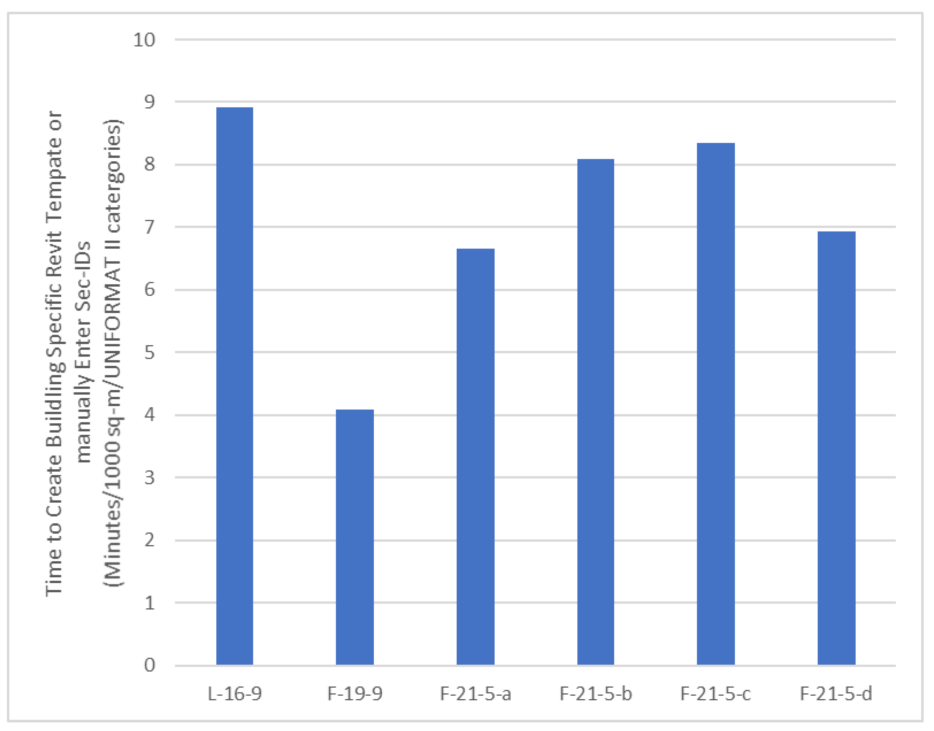
The normalized time to create building-specific Revit templates is given in Figure 6 for six buildings. Time is divided by floor area and number of UNIFORMAT II Categories. For the Loeh method (1 building) this is the time to manually enter SEC_IDs into an already complete Revit model. For the proposed method (5 buildings) this is the time to create the building-specific Revit temple used to create the Revit model. Data compatibility for the one Loeh method building took almost 9 min per 1000 m2 per UNIFORMAT II Category. This was more than all of the proposed method buildings, which ranged from 4 to 8 min per 1000 m2 per UNIFORMAT II Category. The mean and standard deviation for the proposed method buildings is 6.8 and 1.7 min per 1000 m2 per UNIFORMAT II Category, respectively.
4.2. Completing Revit Models (Milestones)
SFC Revit modelers started recording daily logs in 2020, limiting the buildings that could be used in this evaluation to those included in Figure 7 and Figure 8. The data are normalized by floor area. It was not necessary to normalize by the UNIFORMAT II category as all of the buildings have five. The data are not paired. However, they are ordered from least to most floor area within each method.
The first milestone is the time to complete the building envelope (Figure 7). The 2020–21 and 2021–22 students completed this milestone in 1.4 and 1.8 weeks per 1000 m2 on average, respectively. The standard deviations were 0.31 and 0.48 weeks per 1000 m2, respectively. The T-test p-value was 0.2, indicating no statistically significant difference. The second milestone is the time to complete the building interior (Figure 8). The 2020–21 and 2021–22 students completed this milestone in 1.8 and 1.9 weeks per 1000 m2 on average, respectively. The standard deviations were 0.41 and 0.75 weeks per 1000 m2, respectively. The T-test p-value was 0.8, again indicating no statistically significant difference.
4.3. Transferring Data from BUILDER SMS to Revit
The data transfer activities recorded for the proposed method are: the creation of the building-specific Revit template, exporting the Component Section, and Section Details from the BRED database to Excel; exporting Revit element data to Excel for each of the categories; combining Excel sheets from each database; and importing the combined data into the Revit model. These are given in Table 4 for the proposed method buildings.
The Loeh method transfer took 12 min per 1000 m2 per UNIFORMAT II Category [8]. This included manually entering SEC_IDs into the BIM model. The proposed method transfers averaged 14 min per 1000 m2 per UNIFORMAT II Category with a standard deviation of 2.6. The Loeh method transfer was 14% faster than the proposed method. All Revit models (Loeh and proposed method) were error-free with regard to data transfer.
5. Discussion
Ensuring data compatibility for the one Loeh method building took more effort than each of the five building models created using the proposed method. Unfortunately, the center did not have sufficient resources to manually enter SEC_IDs for the L-20-5 buildings, which would have allowed a statistical evaluation between the two methods. This could be completed in a future study.
The variability in time required to ensure data compatibility for the proposed method buildings was partially the result of building variation, e.g., buildings F-21-5-a and F-21-5-d have fewer rooms and, as a result, took less time than F-21-5-b and F-21-5-c. Another source of uncertainty between the two methods is personnel-related. The SEC_IDs were entered by the primary author of Loeh et al. [8]. The building-specific Revit templates were created by the primary author of this article. The time required to complete specific tasks will vary from person to person. The Sustainable Facilities Center (SFC) did not have sufficient resources to control these sources of error.
Data compatibility was ensured in the name-based method by starting model creation with a building-specific Revit template that included all BUILDER SMS SEC_NAMEs for a given building. Data compatibility was ensured in the identifier-based method by entering SEC_IDs after models were created. In each case, this allows for data compatibility to be ensured by following standard protocols to identify and correct errors. Data quality personnel need some knowledge of BUILDER SMS and Revit, but not expertise. Alternatively, SEC_NAMEs and SEC_IDs could be added during model creation by the model creator. This requires expertise in Revit and some knowledge of BUILDER SMS.
Model creation is the most labor-intensive part of the methods evaluated. There was no statistically different difference in the time to complete the models for the two methods, i.e., reach the exterior and interior milestones. We hypothesized that providing object names in a Revit template would quicken the model creation process relative to reading object names from a floorplan. If anything, the opposite occurred.
The variability in time required to create the Revit models could be the result of building characteristics that were not normalized, e.g., the number of rooms. However, one measure related to the number of rooms and the number of scans, does not correlate well, e.g., building F-21-5-b has longer model creation times, but fewer scans than Buildings F-21-5c and F-21-5d. Another source of variability in these results could be personnel-related. The Revit models were created by eight different undergraduates. Though all were taught Revit modeling and supervised by the primary author of this article, they may have varied in previous experience, inherent ability, motivation to do well in the course, and other commitments. The SFC did not have sufficient resources to control these sources of error.
Name-based first-time data transfer was slower because separate transfers were required for each UNIFORMAT II category. A single first-time transfer could be used with the Loeh method. However, all subsequent transfers can be accomplished using the faster identifier-based method, because all parameters can be transferred during any first-time transfer, i.e., SEC_NAMEs during a SEC_ID-based transfer and SEC_IDs during a SEC_NAME-based transfer. It is also possible to automate the first-time transfer to reduce labor time. That was not tested here.
6. Conclusions and Future Work
The proposed method ensures Builder SMS and Revit data compatibility and supports data transfer based on SEC_NAME. This is different from the Loeh method, which bases data transfer on SEC_ID. SEC_NAME is a BUILDER SMS parameter used to store object names derived from the cardinal direction for exterior components and room names for interior components. The names follow the UNIFORMAT II naming convention. SEC_ID is an automatically generated BUILDER SMS parameter used to store a unique alphanumeric identifier for each object. The Loeh method workflow is given in Figure 1. The proposed method workflow is shown in Figure 2. Red elements in Figure 2 are used to identify differences between the methods.
As part of the proposed method, a master Revit template is used to create building-specific Revit templates that, in turn, are used to create data-transfer-compatible models. The Loeh method ensures data compatibility after model creation, by manually entering SEC_IDs into an otherwise completed model. Data control for either method can be accomplished by data management personnel with sufficient knowledge of BUILDER SMS and Revit. Expertise in either application is not necessary. A data personnel with no knowledge of BUILDING SMS or Revit could also coordinate with other professionals with the necessary knowledge. Finally, a Revit professional with some knowledge of data management and BUILDER SMS could add SEC_NAMEs or SEC_IDs during model creation.
We hypothesized that the proposed name-based method would require less effort than the Loeh method because it would be easier to enter and check names for accuracy versus alphanumeric identifiers. This was not the case, as there was little difference in effort between the two methods, as measured by labor-time. The name-based method ensures that names are intuitive and compatible with BUILDER SMS from the start; however, this can be overcome in the Loeh method after the first-time data transfer. The Loeh method must be used when a Revit model is created without BUILDER SMS object names. Where Revit models have yet to be created, either method can be used with little differentiation of effort. The SFC intends to use the method proposed here going forward, as it directly generates models with object names that match BUILDER SMS, before any data transfer.
The experience of the SFC transferring data from BUILDER SMS to Revit—described here and in Loeh et al. [8]—has produced useful insights for any SFM/BIM/combination. Choose and populate the SFM application before creating BIM models, if possible. If the SFM application is chosen first, it can be used to create an appropriate master BIM template containing the relevant building parameters. If the SFM application is also populated first, it can be used—with the master BIM template—to create building-specific BIM templates. This ensures that the SFM parameters and object names are built into the building model. It also identifies relevant objects in BUILDER SMS, ensuring their inclusion in the BIM model. If models are created before an SFM application is chosen, one can follow a standard naming convention compatible with the most likely SFM applications. This should result in a forward-compatible model. If it is not, one can still use the Loeh method for first-time data transfer.
Future work can evaluate/explore other combinations of BIM and FM/SMS applications. With regard to BUILDER SMS, parameters are exported in Industry Foundation Classes format and thus are compatible with all compliant BIM applications. Additional naming conventions could also be studied. Methods to convert BIM or FM/SMS files between naming conventions can be investigated. It is possible, though not proven by this research, that the proposed method will produce fewer errors that are missed by quality control and interfere with initial data transfer. This could be evaluated by monitoring future model creation and data transfers at the SFC or other organizations that use the proposed method.
Supplementary Materials
The following supporting information can be downloaded at: https://www.mdpi.com/article/10.3390/su15021482/s1, Supplementary File: Model creation logs for buildings L-20-5-b and F-21-5-b, and three standard operating procedures: Master BIM Template, Building-specific BIM Template, Data Transfer.
Author Contributions
Conceptualization—J.D.F., J.W.E. and W.T.R.; methodology—J.D.F.; validation—J.D.F.; formal analysis—J.D.F.; investigation, J.D.F.; resources—J.W.E.; data curation—J.D.F.; writing—J.D.F. and J.W.E.; writing—review and editing, W.T.R.; visualization—J.D.F. and J.W.E.; supervision—J.W.E. and W.T.R.; project administration—J.W.E.; funding acquisition—J.W.E. All authors have read and agreed to the published version of the manuscript.
Funding
This research was funded by the New Jersey Department of Military and Veteran Affairs.
Institutional Review Board Statement
Not applicable.
Informed Consent Statement
Not applicable.
Data Availability Statement
All publically available data are provided in this article or the supplemental information. BUILDER SMS and BIM files cannot be shared because of the sequrity needs of the funding agency.
Acknowledgments
BUILDER SMS data were inventoried and entered into BUILDER SMS by Rowan University Sustainable Facility Center staff and undergraduate student interns. Revit models were created by undergraduate students enrolled in the Junior and Senior Engineering Clinic.
Conflicts of Interest
The authors declare no conflict of interest.
References
- UNEP. Buildings and Climate Change: Summary for Decision Makers. United Nations Environment Programme Sustainable Building and Climate Initiative. 2009. Available online: https://wedocs.unep.org/20.500.11822/32152 (accessed on 8 January 2023).
- Energy.gov. An assessment of Energy Technologies and Research Opportunities, Quadrennial Technology Review. 2015. Available online: https://www.energy.gov/sites/prod/files/2017/03/f34/qtr-2015-chapter10.pdf (accessed on 27 November 2022).
- Lee, G.; Sacks, R.; Eastman, C.M. Bim Handbook: A guide to Building Information Modeling for Owners, Managers, Designers, Engineers and Contractors, and Facility Managers; Wiley: Hoboken, NJ, USA, 2012. [Google Scholar]
- Kelly, G.; Serginson, M.; Lockley, S.; Dawood, N.; Kassem, M. BIM for facility management: A review and a case study investigating the value and challenges. In Proceedings of the 13th International Conference on Construction Applications of Virtual Reality, London, UK, 30–31 October 2013. [Google Scholar]
- Barrett, P.; Baldry, D. Facilities Management: Towards Best Practice; Wiley: Hoboken, NJ, USA, 2003. [Google Scholar]
- Fennimore, J. Sustainable Facility Management: Operational Strategies for Today; Pearson: Boston, MA, USA, 2014. [Google Scholar]
- Lavy, S.; Jawadekar, S. A Case Study of Using BIM and COBie for Facility Management. Int. J. Facil. Manag. 2014, 5. Available online: https://www.academia.edu/13095652/A_Case_Study_of_Using_BIM_and_COBie_for_Facility_Management (accessed on 8 January 2023).
- Loeh, R.; Everett, J.W.; Riddell, W.T.; Cleary, D.B. Enhancing a Building Information Model for an Existing Building with Data from a Sustainable Facility Management Database. Sustainability 2021, 13, 7014. [Google Scholar] [CrossRef]
- Motawa, I.; Almarshad, A. A knowledge-based BIM system for building maintenance. Autom. Constr. 2013, 29, 173–182. [Google Scholar] [CrossRef]
- Heaton, J.; Parlikad, A.K.; Schooling, J. Design and development of BIM models to support operations and maintenance. Comput. Ind. 2019, 111, 172–186. [Google Scholar] [CrossRef]
- Lee, S.; Akin, Ö. Augmented reality-based computational fieldwork support for equipment operations and maintenance. Autom. Constr. 2011, 20, 338–352. [Google Scholar] [CrossRef]
- James Herrera, G.J.; Stokes, C.A.; Peña, V.; Howieson, S.V. A Review of the BUILDER Application for Assessing Federal Laboratory Facilities. Institute for Defense Analysis, IDA Document D-8407. 2017. Available online: https://apps.dtic.mil/sti/pdfs/AD1123332.pdf (accessed on 8 January 2023).
- ERDC. BUILDER™ Sustainment Management System. U.S. Army Engineer Research and Development Center. 2012. Available online: https://www.erdc.usace.army.mil/Media/Fact-Sheets/Fact-Sheet-Article-View/Article/476728/builder-sustainment-management-system/ (accessed on 8 January 2023).
- Khemlani, L. The IFC Building Model: A Look Under the Hood. The IFC Building Model: ARCBytes Feature. 2004. Available online: https://www.aecbytes.com/feature/2004/IFC.html (accessed on 8 January 2023).
- Sabol, L. Building Information Modeling & Facility Management; IFMA World Workplace: Dallas, TX, USA, 2008. [Google Scholar]
- GSA. BIM Guide for Energy Performance; GSA BIM Guide Series 05; General Service Administration: Washington, DC, USA, 2009. [Google Scholar]
- Jordani, D.A. BIM and FM: The Portal to Lifecycle Facility Management. J. Build. Inf. Model. 2010, 2010, 13–16. [Google Scholar]
- Chong, H.Y.; Lee, C.Y.; Wang, X. A mixed review of the adoption of Building Information Modelling (BIM) for sustainability. J. Clean. Prod. 2017, 142, 4114–4126. [Google Scholar] [CrossRef] [Green Version]
- Akcamete, A.; Akinci, B.; Garrett, J.H. Potential utilization of building information models for Planning Maintenance Activities. In Proceedings of the EG-ICE 2010—17th International Workshop on Intelligent Computing in Engineering, Leuven, Belgium, 30 June–3 July 2019; ISBN 9781907284601. [Google Scholar]
- Chen, C.; Dib, H.Y.; Lasker, G.C. Benefits of implementing building information modeling for Healthcare Facility Commissioning. In Proceedings of the 2011 ASCE International Workshop on Computing in Civil Engineering, Miami, Florida, 19–22 June 2012; pp. 578–585. [Google Scholar] [CrossRef]
- Becerik-Gerber, B.; Jazizadeh, F.; Li, N.; Calis, G. Application Areas and Data Requirements for BIM-Enabled Facilities Management. J. Constr. Eng. Manag. 2012, 138, 431–442. [Google Scholar] [CrossRef]
- Costin, A.; Shaak, A.; Teizer, J. Development of a navigational algorithm in BIM for effective utility maintenance management of facilities equipped with passive RFID. In Proceedings of the 2013 ASCE International Workshop on Computing in Civil Engineering, Los Angeles, CA, USA, 23–25 June 2013; pp. 653–660. [Google Scholar] [CrossRef]
- Volk, R.; Stengel, J.; Schultmann, F. Building Information Modeling (BIM) for existing buildings—Literature review and future needs. Autom. Constr. 2014, 38, 109–127. [Google Scholar] [CrossRef] [Green Version]
- Yin, X.; Liu, H.; Chen, Y.; Wang, Y.; Al-Hussein, M. A BIM-based framework for operation and maintenance of utility tunnels. Tunn. Undergr. Space Technol. 2020, 97, 103252. [Google Scholar] [CrossRef]
- Ede, A.N.; Olofinnade, O.M.; Sodipo, J.O. Use of Building Information Modelling Tools for Structural Health Monitoring. In Proceedings of the 2017 International Conference on Computing Networking and Informatics (ICCNI), Lagos, Nigeria, 29–31 October 2017. [Google Scholar] [CrossRef]
- Orr, K.; Shen, Z.; Juneja, P.K.; Snodgrass, N.; Kim, H. Intelligent facilities: Applicability and flexibility of open BIM standards for operations and maintenance. In Proceedings of the 2014 Construction Research Congress, Atlanta, GA, USA, 19–21 May 2014; pp. 1951–1960. [Google Scholar] [CrossRef] [Green Version]
- Lin, Y.C.; Su, Y.C. Developing mobile- and BIM-based integrated visual facility maintenance management system. Sci. World J. 2013, 2013, 124249. [Google Scholar] [CrossRef] [Green Version]
- Sacks, R.; Eastman, C.M.; Ghang, L.; Teicholz, P.M. BIM Handbook a Guide to Building Information Modeling for Owners, Designers, Engineers, Contractors and Facility Managers, 3rd ed.; Wiley: Hoboken, NJ, USA, 2018. [Google Scholar]
- Tsay, G.S.; Staub-French, S.; Poirier, É. BIM for Facilities Management: An Investigation into the Asset Information Delivery Process and the Associated Challenges. Appl. Sci. 2022, 12, 9542. [Google Scholar] [CrossRef]
- Di Filippo, A.; Victoria Andrea Cotella, V.A.; Guida, C.G.; VMolina, V.; Lorena Centarti, L. BIM Interoperability and Data Exchange Support for As-Built Facility Management. In Proceedings of the Computational Science and Its Applications—ICCSA 2021: 21st International Conference, Cagliari, Italy, 13–16 September 2021; Gervasi, O., Murgante, B., Misra, S., Garau, C., Blecic’, I., Taniar, D., Apduhan, B.O., Rocha, A.M., Tarantino, E., Torre, C.M., Eds.; Springer Nature: Berlin/Heidelberg, Germany, 2021. [Google Scholar] [CrossRef]
- Thabet, W.; Lucas, J.; Srinivasan, S. Linking life cycle BIM data to a facility management system using Revit Dynamo, Operation. Technol. Manag. Constr. 2022, 14, 2439–2558. [Google Scholar]
- ERDC. Army BUILDERTM SMS Inventory and Assessment Guide. U.S. Army Engineer Research & Development Center. 2017. Available online: https://buildersummit.com/wp-content/uploads/2018/11/Army-BUILDER-SMS-Inventory-and-Assessment-Guide_20170629.pdf (accessed on 8 January 2023).
- Autodesk. Revit Support and Understanding: Understanding Families. 2021. Available online: https://knowledge.autodesk.com/support/revit/learn-explore/caas/video/youtube/lesson/143349-courseId-100332.html (accessed on 8 January 2023).
- Charette, R.; Marshall, H. UNIFORMAT II Elemental Classification for Building Specifications, Cost Estimating and Cost Analysis, NIST Interagency/Internal Report (NISTIR) 6389; National Institute of Standards and Technology: Gaithersburg, MD, USA, 1999. [Google Scholar]
- NJDMAVA. NJDMAVA Information Security Program. New Jersey Department of Military and Veterans Affairs. Departmental Directive 25.2.3. 2006. Available online: https://www.nj.gov/military/publications/dd/DD25.2.3.pdf (accessed on 8 January 2023).
Figure 1.
Loeh workflow for BIM and BUILDER SMS data transfer [8].
Figure 1.
Loeh workflow for BIM and BUILDER SMS data transfer [8].

Figure 2.
Proposed workflow for BIM and BUILDER SMS data collection and integration.

Figure 3.
BUILDER SMS Naming Convention for external walls.

Figure 4.
Component Section Query.

Figure 5.
Revit model for F-19-9.

Figure 6.
Time needed to ensure data compatibility.

Figure 7.
Model Completion Milestone 1. The lowercase letters refer to Table 3.
Figure 7.
Model Completion Milestone 1. The lowercase letters refer to Table 3.

Figure 8.
Model Completion Milestone 2. The lowercase letters refer to Table 3.
Figure 8.
Model Completion Milestone 2. The lowercase letters refer to Table 3.


Table 1.
Loeh and Proposed Methods.
| Loeh | Proposed |
|---|---|
| Create Model | Create Building-Specific Revit Template |
| Enter SEC_ID values into Model | Create Model |
| Check Model SEC_IDs | Check Model SEC_NAMEs |
| Transfer Data using SEC_ID | Transfer Data first time using SEC_NAME |
| Transfer Data subsequent times using SEC_ID |
Table 2.
Standard Section Names and Format Rules.
| Use | Standard Section Name |
|---|---|
| Section by Floor | FL1—1st Floor, FL2—2nd Floor, FL3—3rd Floor, etc. |
| Section by Floor | BASEMENT, MEZZANINE, ATTIC, etc. |
| Section by Wing | MAIN, WING A, WING B, WING C, ADDITION, etc. |
| Section by Direction | NORTH, EAST, WEST, SOUTH |
| Section by Roof Level | UPPER, LOWER, MAIN |
| Section by Room | RM 109, LOBBY, KITCHEN, BOILER RM, etc. |
Table 3.
2020–21 Building Summary.
| Designation * | Year Modeled (Academic) | Decade Built | Area Range (1000 m2) | Scans |
|---|---|---|---|---|
| L-16-9 | 2016–17 | 1980 | 1.4–1.5 | 40 ** |
| F-19-9 | 2019–20 | 1960 | 1.3–1.4 | 36 |
| L-20-5-a | 2020–21 | 1950 | 1.6–1.7 | 64 |
| L-20-5-b | 2020–21 | 1960 | 2.7–2.8 | 79 |
| L-20-5-c | 2020–21 | 1970 | 3.0–3.1 | 110 |
| L-20-5-d | 2020–21 | 1940 | 3.2–3.3 | 86 |
| F-21-5-a | 2021–22 | 1980 | 1.1–1.2 | 19 |
| F-21-5-b | 2021–22 | 1960 | 1.6–1.7 | 58 |
| F-21-5-c | 2021–22 | 1950 | 3.1–3.2 | 157 |
| F-21-5-d | 2021–22 | 1930 | 4.6–4.7 | 195 |
* The initial letter indicates Loeh (L) or Proposed (F) method. “F” stands for Foster. The first number is the year the building was scanned, e.g., 16 means 2016. The second number is the number of UNIFORMAT II categories included in the model, e.g., 5 means five categories. A final small letter is included to differentiate buildings that would otherwise have the same designation. ** Estimated. This was the first BIM model created at the SFC; scan information is not available.
Table 4.
Proposed Method Data Transfer Times, minutes.
| Building | Building-Specific Revit Template | Exporting Details | Exporting Elements | Combining Sheets | Importing Combined Data |
|---|---|---|---|---|---|
| F-19-9 | 52 | 27 | 45 | 45 | 20 |
| F-21-5-a | 38 | 9 | 15 | 15 | 6 |
| F-21-5-b | 67 | 15 | 25 | 25 | 10 |
| F-21-5-c | 130 | 15 | 25 | 25 | 10 |
| F-21-5-d | 162 | 15 | 25 | 25 | 10 |
Disclaimer/Publisher’s Note: The statements, opinions and data contained in all publications are solely those of the individual author(s) and contributor(s) and not of MDPI and/or the editor(s). MDPI and/or the editor(s) disclaim responsibility for any injury to people or property resulting from any ideas, methods, instructions or products referred to in the content. |
© 2023 by the authors. Licensee MDPI, Basel, Switzerland. This article is an open access article distributed under the terms and conditions of the Creative Commons Attribution (CC BY) license (https://creativecommons.org/licenses/by/4.0/).
Share and Cite
MDPI and ACS Style
Foster, J.D.; Everett, J.W.; Riddell, W.T. Compatibility of Sustainable Facility Management and Building Information Modeling Applications: The Role of Naming Conventions. Sustainability 2023, 15, 1482. https://doi.org/10.3390/su15021482
AMA Style
Foster JD, Everett JW, Riddell WT. Compatibility of Sustainable Facility Management and Building Information Modeling Applications: The Role of Naming Conventions. Sustainability. 2023; 15(2):1482. https://doi.org/10.3390/su15021482
Chicago/Turabian StyleFoster, John D., Jess W. Everett, and William T. Riddell. 2023. "Compatibility of Sustainable Facility Management and Building Information Modeling Applications: The Role of Naming Conventions" Sustainability 15, no. 2: 1482. https://doi.org/10.3390/su15021482
Note that from the first issue of 2016, this journal uses article numbers instead of page numbers. See further details here.