1. Introduction
Within modern industry, design for sustainability practices are implemented inside technical departments to fulfill new requirements dictated by social challenges (e.g., sustainable development goals), market needs (e.g., reducing energy consumption in use, extending product life cycle), and legislation constraints (e.g., regulation compliance). Design for sustainability (also called environmentally conscious design or ecodesign) is recognized as the inclusion of environmental attention in engineering design and emerges as a novel paradigm in product development [
1,
2]. Particularly affected by these requirements are electro–mechanical products (e.g., household appliances), which are classified as energy-related products [
3]. For this product category, a regulatory framework has been issued to tackle the importance of energy consumption and related emissions [
4,
5,
6,
7,
8,
9]. In order to fulfill the specific needs of energy-related products and to deal with the requirements defined within this framework, the adoption of virtual design tools (like Computer-Aided Design—CAD and Computer-Aided Engineering—CAE) in the design for sustainability methodology is key [
10,
11]. A few attempts describe the possible integration of CAD and Life Cycle Assessment—LCA tools [
12,
13], or the use of simulation tools to predict product energy performance [
14]. However, these theoretical approaches are often characterized by data exchange issues (e.g., data interoperability) [
15,
16] and difficulties in capitalizing engineering knowledge [
17].
Legislation forces manufacturers to focus on strategies for the reduction of energy consumption rather than following or defining procedures to integrate design for sustainability principles inside product development processes [
18]. Thus, several issues arise from the practical implementation of design for sustainability in technical departments. The landscape of these methodologies and tools appears fragmented, marked by the diversity of purposes they serve [
19,
20,
21,
22,
23]. Specific knowledge and time are required due to methodology over-formalization [
24,
25,
26,
27,
28,
29] and difficulties in managing trade-offs among key variables (e.g., time, costs, performance), which occur when environmental strategies are integrated into the product development process [
30,
31]. Near to these limitations, the lack of support in knowledge creation and sharing is recognized as one of the reasons that increases the company’s resistance to applying ecodesign methods and tools [
32,
33].
Therefore, the implementation of energy efficiency tests on prototypes represents a substantial activity that has specific and high costs for companies. The need for tangible support and engineering tools allows for achieving these advantages [
34,
35,
36,
37]. Following this new challenge, two research questions arise from the literature:
Is it possible to effectively support and integrate design for sustainability strategies in the development of energy-related products, and how?
Is it possible to adopt virtual prototyping tools to derive engineering eco-knowledge, reducing the need for physical prototypes?
Starting from these two research questions, this present paper proposes a CAE-based methodology to assist engineers in the development of energy-related products aligned with ecodesign standards and certifications. The backbone of this research methodology is to make use of virtual prototypes to simulate the operating conditions of mechatronic products following the boundary conditions proposed by the ecodesign regulations and energy label directive. The methodological framework proposed in this research provides the definition of eco-knowledge from simulations of virtual prototypes and allows for their collection in a structured database. The goal is to put into practice a novel approach for gathering, sharing, and reusing eco-knowledge with the aim to support engineers in the development of industrial products that fit with design for sustainability principles. The result leads to the reduction of time and costs in the development of energy-related products, improving energy performance and anticipating real tests and prototypes.
Facing the current limitations of research approaches on this subject, the proposed methodology has a few novel aspects, such as (i) design tool interoperability (design and virtual prototyping tools) to widen the analysis perspective; (ii) multi-physics simulations to account simultaneously or sequentially for multiple physics models, considering their mutual influence in design choices; (iii) eco-knowledge formalization among different engineering departments; and (iv) ecodesign rules and guidelines definitions for designing sustainable products with a focus on environmental considerations.
2. CAE-Based Ecodesign Methodology
To describe the CAE-based ecodesign methodology and the related features, firstly, the process workflow is presented (
Section 2.1), and secondly, solutions to store/reuse eco-knowledge (e.g., a repository for data collection) are proposed (
Section 2.2).
2.1. Methodology and Workflow
Product development is a consolidated process that encompasses the following steps: (i) planning and tasking, (ii) conceptual design, (iii) embodiment design, (iv) detail design, (v) prototyping and testing, and (vi) product design review [
38,
39]. The CAD tool is usually used to perform the activity related to the embodiment design phase and to generate the overall geometry of the product (3D model). CAE tools are then adopted after the CAD modeling when the virtual model of the product is available to validate engineering choices and perform different analyses.
Figure 1 provides an overview of how the CAE-based ecodesign methodology fits into the conventional workflow of the product development process.
In accordance with the overall methodological framework, three main steps characterize its development (workflow): (i) modeling, (ii) simulation, and (iii) validation. To deal with these steps, three environments are necessary to properly develop the proposed methodology: (i) CAD environment, (ii) CAE environment, and (iii) experimental test environment (
Figure 2).
Step 1—Modeling. The product modeling is the first step to tackle when applying CAE-based ecodesign methodology. Within this environment, a product virtual model is built using a 3D CAD tool. Three-dimensional CAD development encompasses two phases: (i) part modeling and (ii) product assembly. Part modeling provides the definition of all geometrical features of each part/component using the parametric approach. Indeed, geometrical features are linked with dimensions by parametric rules. In this phase, it is necessary to define geometrical inputs (dimensions, shapes, etc.) with the parametric approach, as well as physical inputs (material, attributes, etc.). Part simplification is encouraged to speed up the performance of the virtual simulation process. Small geometric features can rise up significantly (up to ten times) the discrete physical simulation, as well as the model errors, without significantly enhancing the quality of the results [
40,
41]. Concurrently with part modeling, product assembly is performed by defining modules (sub-assemblies) and related constraints. This phase is also relevant because, for example, during the CAE analysis, only a few modules can be involved, simplifying the complexity and the time necessary for the simulations.
Step 2—Simulation. Virtual prototyping analysis is the second step to tackle during this process. Within this environment, the 3D CAD model is imported from the previous step and different CAE tools can be used based on the physics to simulate. For example, for energy-related products such as washing machines or cooker hoods, fluid dynamics and thermal analyses are necessary to investigate the motion of the fluid and the performance of the system, while electromagnetic simulation is necessary to analyze the performance of electric motors used in these products. On the other hand, for other products such as an induction hob, thermal analysis needs to be coupled with electromagnetic simulation. A virtual prototype is used, and a numerical approach is employed to simulate product behavior under certain working conditions. Within this environment, after the definition of physical phenomena to simulate (multi-physics model), other mandatory steps are necessary, such as the definition of boundary condition, the geometry discretization (mesh definition), and other settings based on the CAE systems that are used for the simulations. Regardless of the adoption of a specific software tool, the simulation process is carried out in three steps: pre-processing, processing, and post-processing. During the pre-processing phase, the numerical model is built starting from the discretization of the CAD model (mesh) and ends with the set-up of boundary conditions. The set-up phase encompasses the right choice of physics to simulate (structural, fluid-dynamic, modal, etc.), the equations used within the model, and the other working settings of the product (e.g., loads, constraints, temperature). The processing phase deals with the equation assessment while the final step is post-processing, where the results are managed and processed. Within the same CAE environment, an s-LCA analysis is performed using a dedicated software tool that calculates the environmental footprint of the product starting from the 3D CAD model. The s-LCA tool is already available in several commercial applications [
42,
43]. Each time a design review is implemented in the CAD environment, this change is processed by the CAE environment with both side numerical simulation and s-LCA.
Step 3—Validation. Experimental evaluation is the third step to tackling the development of the methodology. Within this environment, the physical prototype is manufactured, and it is used to perform energy tests and retrieve related Key Performance Indicators (KPIs). With this aim, together with the product prototype, a test bench is necessary. The test bench needs to be built in full compliance with the standard requirements reported in the energy-labeling directives for these products. The test bench allows for recreating the working condition of the product and replicating the procedure reported within the energy label directive. Equipment and sensors required for the measurement of energy consumption and other parameters are necessary for this aim. Once a product prototype and the test bench are built, energy consumption tests are carried out following the procedure described within the ecodesign directive for energy labeling. The tests are made in several working points based on the features of the product, and they are repeated for statistical reliability. The results are collected and manipulated to create a fitting with the results obtained from the CAE simulations, including the calculation of errors. In this phase, it is not required to build a prototype for each product of the same family, but this phase aims to validate the results obtained from the virtual prototyping phase with a benchmark. Thus, the results obtained by testing the product prototype (in full compliance with the procedure specified in the ecodesign directive—energy labeling) are used as a benchmark. There is an iterative process to set the model developed within the CAE environment until this model has a gap with the real test lower than 10%, which is considered acceptable for this kind of simulation.
All the design reviews are managed within this framework and stored in the repository.
2.2. Knowledge Database
The kernel of the proposed methodology is the repository, in which ecodesign guidelines, virtual prototyping studies, and LCA results are stored and organized to facilitate access. The database is used for two main purposes: the first one is to store and collect data within a dedicated format (table structure), and the second one is to retrieve useful information during product design by smart algorithms. The structure of the database is characterized by levels and sections, as presented in
Figure 3.
The first partition of the database concerns the environmental guidelines and tools to follow during the application of the methodology. This section encompasses (i) product requirements (e.g., standards requirements and related documentation), (ii) general environmental rules coming from the literature (e.g., the ten golden rules of ecodesign), and (iii) specific environmental rules coming from internal knowledge (e.g., ecodesign rules retrieved by the experience). The second partition concerns the virtual analysis of the product performed in different product configurations. This section encompasses (i) the collection of 3D CAD models (e.g., parts, modules, and assemblies) with specific product features and design solutions; (ii) results from virtual energy tests and simulations, including the related documentation; and (iii) the evolution of the product to fit the ecodesign requirements (e.g., past design choices and rationale to cope with specific issues). The third partition concerns the environmental product performance by means of the s-LCA analysis. This section encompasses the results of the environmental analysis of the different product configurations in terms of environmental indicators (e.g., Global Warming Potential, resource consumption). These three partitions are defined by dedicated objects (tables) that collect related data held in a table format within a relational database.
It is worth noticing that for database filling (data collection and creation of eco-knowledge), at the first deployment of the database, only ecodesign guidelines retrieved from the literature are stored and available [
44,
45,
46,
47,
48,
49,
50,
51,
52], as well as past environmental studies when available. Afterward, during the implementation and use of the proposed methodology, the repository is enriched every time a new virtual simulation is performed, as well as a new guideline is derived from the company. Data stored within the database sections are used by designers for assessing the environmental impact of product modules and components throughout the design stages. Different approaches are adopted to run the highest number of virtual simulations and to fill the database. For example, Design of Experiments (DoE) permits the variation of different factors (design features) simultaneously to screen the reaction space for optimum values. All the derived simulations (both CAE and s-LCA) allow for building company knowledge and sharing it inside a manufacturing company to undertake ecodesign actions. Product engineers oversee both data and results to establish ecodesign rules and guidelines. Their objective is to comprehend the relationship between design decisions and their environmental consequences. Both internal eco-knowledge and general guidelines are stored within the database to have a critical focus on the product under design and to foresee, quantitatively, the environmental impacts of design choices. Guidelines are established with attributes and compiled through a hierarchical structure. The guidelines are organized in a table form and classified based on six classes:
Product Type: Guidelines that affect specific families of energy-related products (e.g., hobs, ovens, vacuum cleaners, tv). Some of them have general applicability, while others are specific to a product family.
Product Module: Guidelines that affect the whole product or a given module, addressing changes in product or component functionalities.
Interested design phase: Guidelines that refer to a specific product development stage. This attribute indicates at which stage of the design phase a guideline can be implemented, in accordance with the classification provided by Pahl and Beitz [
38].
User: Some guidelines are relevant for every user involved in the product development process, while others recommend a specific solution tailored to a particular technical aspect, involving individuals responsible for implementing the guideline.
Source: Guidelines can be retrieved from different sources. A guideline may be sourced from the literature or gathered from the personal expertise of designers, ecodesign researchers, or internal knowledge of the company.
Category: This class refers to the life cycle phase affected by the implementation of the guideline (e.g., design, use, end-of-life). They ensure the ability to perform a thorough analysis of environmental issues.
In each one of the mentioned classes, related documentation is uploaded, including, for example, standards, CAD models, CAE simulations, s-LCA analysis, etc. By associating these attributes with each guideline, users can query the database to retrieve the most appropriate guidelines based on the project objective.
After filling the database, querying is a necessary step to reuse engineering eco-knowledge. The objective of a smart database querying tool is to gain a list of useful design rules. The graphic user interface (GUI) of this tool is characterized by two main sections. The first section is related to filtering, and it enables users to query the database based on specific attributes. The second section pertains to the display of filtered guidelines. Other options related to these two sections are available for the user, such as (i) ecodesign score, which shows the importance of the guideline based on sustainability level, pertinence in design phases, and correlation with product life cycle phases, and (ii) applicability score, which provides information about the pertinence in the own contest of the guideline. Once suggested guidelines are provided to the users, deeper analysis and design solutions become available. Firstly, product virtual analysis increases the awareness of designers about the provided guideline, extending the range of information about the product. This database section relies on storing virtual analyses and comparing them with experimental results to steer the product design generation process (
Figure 4A).
Through consultation of virtual tests, designers gain insights into various aspects, including (i) multiple product configurations (physical and functional interrelations of each component and functionality relation with each component), (ii) working set points and performances (energy consumption tests and associated performance), (iii) geometric parameters (sizes, shapes, and dimensions), (iv) materials and their characteristics, and (v) energy efficiency class based on testing activities performed in a given product configuration. Concurrently with the analysis of CAE simulations, the decision-making process in the early phases of the product development phase can be supported by much of the data related to the virtual environmental analysis (s-LCA). In addition, designers can navigate the database Life Cycle Assessment, toxicity matrix, assembly, and disassembly aspects of products and/or modules (
Figure 4B). This database archives previous internal studies and LCA analyses, LCA studies conducted by external consultants, regulations concerning material usage, as well as internal company regulations, among other sources. By consulting virtual tests, designers gain insights into (i) carbon footprints in different life cycle phases, (ii) material toxicity and material compatibility (e.g., plastic compatibility chart), (iii) materials information (e.g., environmental properties and embodied energy), (iv) assembly and disassembly aspects, and (v) LCA evaluation, considering other environmental indicators and performance.
Another way to access the database and to have a smart filtering process is the use of artificial intelligence. Artificial intelligence has become widely used in daily practices; however, its implementation in engineering design is still limited. In this case, a neural network (i.e., large language model—LLM) can be used with this aim in mind, and different models and algorithms can be adopted (e.g., self-supervised learning model, supervised fine-tuning model) to train the model based on the collected analyses [
53,
54].
3. Case Study: Induction Hob
The presented methodology was applied to a specific product family (i.e., induction hob, which is an energy-related product). This case study was selected to demonstrate the applicability of the methodology and the related outcomes in one of the most challenging products where thermal and magnetic simulations are coupled. Induction cooking (
Figure 5) transfers heat to the pan through a magnetic field generated beneath the ceramic plate. The heat produced in the pan is conducted in the glass via thermal contact conductance.
This technology results in higher efficiency since most of the heat generated is transferred directly to the food. In the following part of this section, the proposed methodology related to the induction hob case study is described in detail. Like most household appliances, induction hobs are subject to energy consumption standards, which establish criteria and procedures for evaluating the performance of electric hobs in domestic applications. The energy consumption test is representative of a real cooking process where, after the first heating phase, the boiling and simmering phases follow. Other than the energy performance requirements, in the early stages of product development, it is necessary to define the geometric information, the principal components materials, and the functional parameters. In the frame of this use case, the principal product information considered is the following:
Case dimension: 30 × 60 mm.
Number of cooking zones: two.
Maximum power: 7000 W (3500 W for each cooking zone).
Energetic label: A+ class.
Once the general requirements of the hob are established, the product is analyzed considering the functional and modular analysis. In this case, the product was characterized by seven modules, as reported in
Table 1. Each module collects several functions derived from the functional analysis.
The transition from product modules to potential design solutions involves various tools, such as patent searches and brainstorming activities, among others. A particularly valuable tool in this process is the morphological matrix, which enhances the efficacy of conceptual analysis by translating functional modules into physical ones. A morphological matrix is built by labeling each row with all identified product modules and, for each module, enumerating the potential design options as columns (
Figure 6).
After this preliminary phase which encompasses the first phase of the product development process (planning, tasking, and conceptual design) the CAE-based ecodesign methodology is applied following the three previously identified steps.
3.1. Step 1—Modeling
Considering the information defined in the conceptual design, the virtual model of the hob containing all the product information and manufacturing, energy, and environmental data is designed and developed through the CAD environment (i.e., SOLIDWORKS
®). Product design originates from the input parameters and the information of the previous model, which are already available as a company know-how. Two different models are developed in this phase: the first one concerns the product model used for production, while the second one concerns the system model, which is a simplified version of the first CAD model with additional items used for numerical simulation (see the virtual model in
Figure 7). For the first one, each product component is designed in the part environment and assembled in the assembly environment. For the second one, the whole system is modeled, including the surrounding parts, which interact with the product under investigation.
3.2. Step 2—Simulation
Starting from the previously developed CAD model, additional geometrical simplifications are carried out: (i) a cylindrical wire with the same diameter is used to model the Litz wire, (ii) an empty cylinder without handles is used to model the pot, and (iii) a solid volume within the pot is used to model the water. For the pot and the water, the standard requirements (EN 60350-2 [
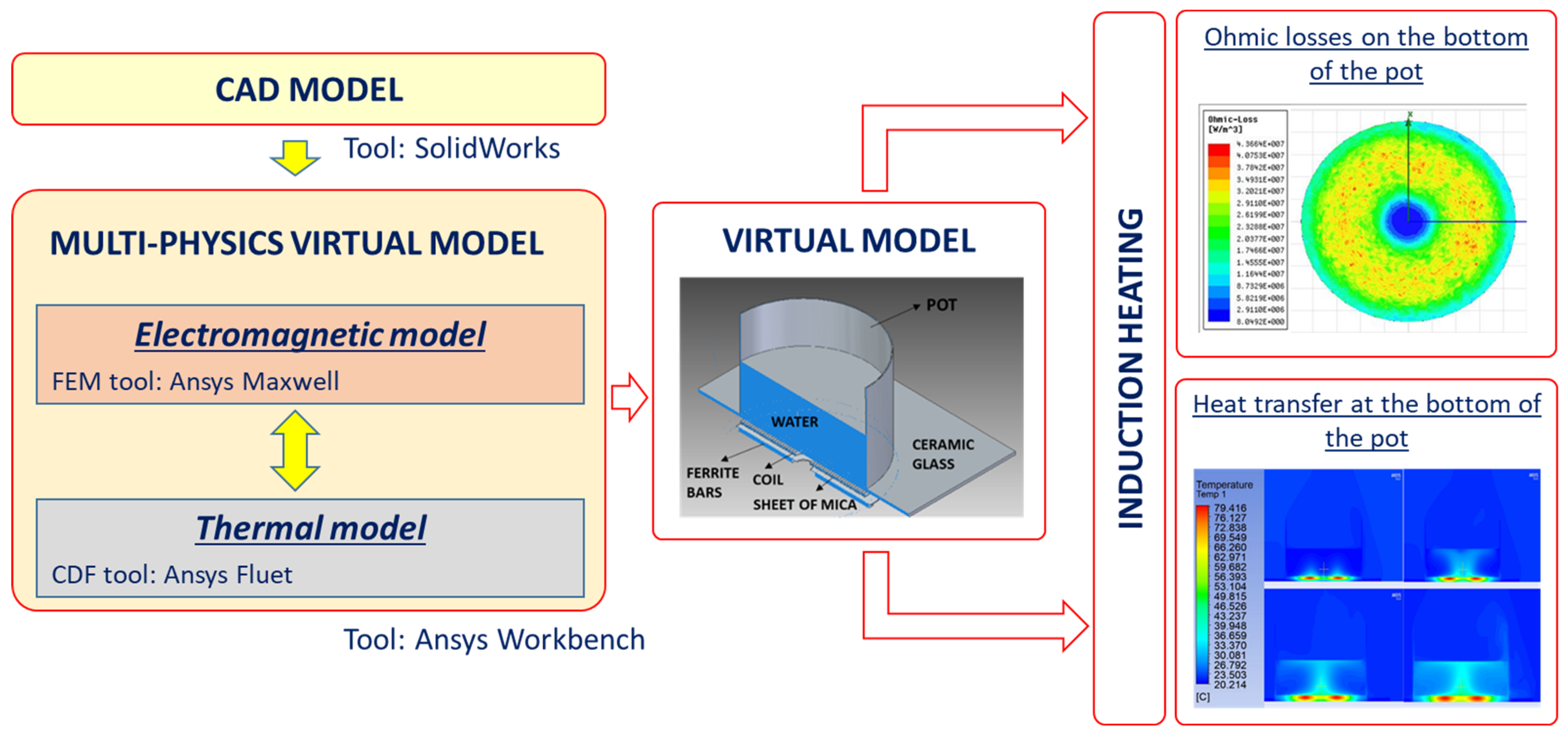
55]) are used for the geometrical definition. The water is not considered in the electromagnetic analysis since it is not affected by the generation of ohmic losses. The volume of air around the model is modeled as a cubic box. The multi-physics model is built by coupling thermal and electromagnetic aspects (
Figure 7). The thermal model deals with the thermodynamics laws, while the electromagnetic model deals with the Maxwell equations. Following the principle of multi-physics simulations and the case study under analysis, the output of the electromagnetic model is the input of the thermal model. Based on the current and frequency passing through the copper coil, it becomes feasible to assess the eddy currents produced on the bottom of the pot and the corresponding heat generated via the Joule effect. This heat derived from the electromagnetic model serves as an input for the thermal module, enabling simulation of the product’s fluid-dynamic behavior. It is worth noting that for both models (electromagnetic and thermal) the eddy current losses and heat dissipation play a critical role in the general model validation. Losses are considered not only by the definition of the system geometry but also by a proper setting of the system boundary conditions. This involves assigning the correct materials to each component (e.g., stainless steel for the pan, ceramic glass for the hob’s top surface, and air for the surrounding environment), the material properties (e.g., thermal conductivity), and the interfaces’ characterization, among other factors. Therefore, the boundary conditions reflect the real electromagnetic and heat transfer mechanisms.
The virtual model covers information about the product, allowing for a simulation of its real use in compliance with the EU Directive. FEM and CFD tools, integrated within the ANSYS
® WORKBENCH (2022 R2) application, are coupled to concurrently address the electromagnetic and thermal–fluid dynamic behavior of the analyzed product. For accurate FEM and CFD analysis, the system is discretized into a grid (mesh) made up of finite elements (e.g., triangles) fitting the geometries of the elements in the model. An iterative solution of the time-harmonic electromagnetic problem and the transient thermal one (transient effects) is used to characterize the induction heating phenomenon (
Figure 8) since the system undergoes changes in temperature over time due to a setting variation in the cooking process established by the standard. Accounting for transient heat dissipation at the model boundary ensures a comprehensive understanding of the system’s thermal behavior under different operating conditions.
In the same CAE environment, a simplified Life Cycle Assessment (s-LCA) is performed using the SUSTAINABILITY tool developed by SOLIDWORKS
® [
43]. Indeed, all necessary data are available to perform this life cycle analysis and to foresee environmental impacts related to the developing hob.
3.3. Step 3—Validation
To assess the robustness of the virtual model and to validate it, experimental tests are required for comparison, following the testing procedure stated within the directive. The model validation consists of comparing outputs from the experimental system to virtual model outputs for the same set of input conditions (
Figure 8 and
Table 2).
The input parameters required for the analysis are retrieved by the European Standard EN 60350-2:2018 [
55], while the experimental tests are carried out in compliance with the Energy Labeling Directive (Directive 2010/30/EU). Within the experimental test environment, the execution of the test in a controlled environment equipped with dedicated sensors allows for the evaluation of the total current absorbed from the grid. Moreover, to determine the energy efficiency of the hob, it is necessary to measure the thermal powers exchanged.
Figure 9 shows the experimental bench used for thermal tests. It consists of a set of metallic pots and lids (made of conductive stainless steel) with a different diameter (e.g., 150, 180, and 210 mm). The lid presents a circular pattern of holes, and it is equipped with a plastic cylinder (polyamide PA6.6) that hosts the thermocouple necessary to measure the water temperature.
The pot is positioned in the cooking zone of the induction hob, and the thermocouple allows for determining the temperature variation of the water inside the pot. By solving the thermodynamics equations, the different thermal powers are assessed (
Figure 10). The energy required during the execution of the test determines the energy class of the product. The different thermal powers of
Figure 10 are the in/out heat flows of the considerate system.
Q_heat_up_water is the thermal power needed to heat the water;
Qconv is the heat loss by convection from the pot, lid, and glass–ceramic plate; and
Qrad is the heat loss by radiation from the pot and lid. The heat required for the phase change (
Qvap) is also considered during the preheating and simmering phases. The red line in
Figure 10 shows the total power required over time.
Once the virtual model is validated, a list of virtual simulations is performed to understand the effect of the changes in design parameters. In this specific case study, three different groups of parameters are identified: (i) geometrical, (ii) functional, and (iii) material. Geometrical parameters are reported in
Table 3, while material and functional parameters are shown in
Table 4 and
Table 5, respectively.
A Design of Experiments (DoE) matrix is generated using the Latin Square function to minimize the required number of experiments, while simultaneously understanding the impact of each parameter on the product. Useful data, results, outputs, and guidelines are derived to be stored in the database to build the specific company knowledge. All these data are organized in a structured way to be easily retrievable during a database query.
4. Results and Discussion
The presented approach proposes the use of engineering virtual prototyping tools and their interoperability in the development of energy-related products. The results obtained using different engineering software tools allow for the creation of specific knowledge in the field of ecodesign. The proposed methodology is an attempt to anticipate issues and concerns related to the development of ecodesign-compliant products, avoiding time-consuming laboratory tests and costly prototypes. It provides different levels of integration within the product development process. The first level of integration deals with the concept of concurrent engineering, keeping the same steps of the traditional product development process, trying to close the gap between steps with the aim to overlap some phases and reduce the project’s lifetime. The second level of integration deals with the adoption of software systems for project management (e.g., PDM and/or PLM systems), in which the proposed repository can be considered a complementary part of the data management system, able to create proper knowledge on ecodesign and design for sustainability. The hob case study provides an example of eco-knowledge gained through simulating various product configurations using the validated model. The eco-knowledge is then properly stored in the system repository (CAE-based ecodesign methodology database), and the information available from the database can be reused depending on the specific design phase: (i) planning and tasking, (ii) conceptual design, and (iii) embodiment design. An example of the ecodesign guidelines for the conceptual design phase is presented in
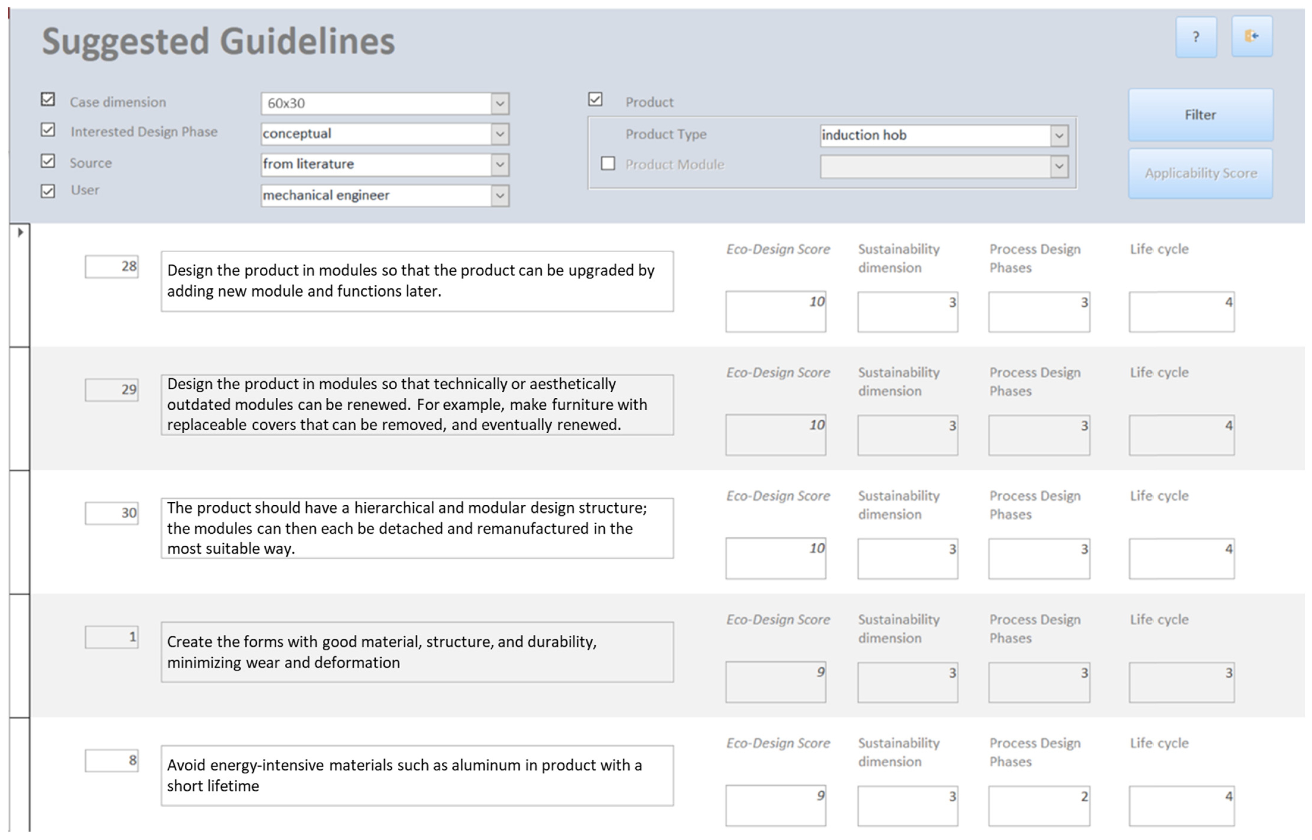
Figure 11. It is worth mentioning that the database is developed with the Microsoft Access application and the graphic user interface of the Visual Basic tool. The general guidelines obtained for the conceptual design phase are retrieved by querying the database in relation to the type of product (i.e., induction hob), external case dimensions (i.e., 60 × 30), design phase (i.e., planning and tasking), source of guidelines (i.e., from the literature), and the user (i.e., mechanical engineer). In this case, the tool provides a specific set of information and the main guidelines retrieved for this phase. The guidelines reported in
Figure 11 are general ecodesign principles that need to be applied to the first design iterations. These guidelines are generic for the main modules identified by the functional analysis and can be adopted at the conceptual level by system engineers to develop more sustainable solutions and product architectures without entering too much detail about the product components and characteristics.
Going further in the design phase (embodiment design), it is possible to foresee an assessment of the environmental impact. By querying the database, ecodesign guidelines referring to the s-LCA are available to provide a clear understanding of the environmental issue related to the product from a life cycle perspective. Indeed, looking at the different life cycle phases, the use phase appears to be the most critical one, followed by the raw materials and manufacturing phases. The use phase accounts for more than 90% of the overall impacts (considering a generic EU energy grid mix) in terms of air emissions (Global Warming Potential—GWP). This result highlights that minimizing energy consumption during product use leads to the most important reduction in environmental impacts for this type of product. For each module described in the conceptual design phase, environmental impacts are measured to identify environmental hot spots and then increase product performance. Concerning the raw materials and the manufacturing phase, two main issues arise from the s-LCA analysis dealing with the “Electronic System” module and the “Energy Converter” module. These two modules account for more than 50% of the overall impacts of component manufacturing since the type of materials and the quantity used for electronic components and the coils cause a significant impact in terms of GWP. Ecodesign guidelines are defined in this phase following the outcome of the virtual simulation process and the s-LCA to provide useful information to designers and engineers.
Finally, concerning the guidelines to implement in the detail design phase, it is necessary to refine the level of detail used for the database query. The graphic user interface is similar, but a definition of technical product features (i.e., the energy efficiency class) is required. An example is presented hereafter with a focus on a specific hob component: the coil (
Figure 12). Ecodesign guidelines for coil components are more detailed than in the previous step, including the type of material necessary to increase product performance (e.g., aluminum alloy or copper), geometrical features (e.g., the gap between the coil and the bottom of the pot), dimensions (e.g., wire diameter), etc.
The eco-knowledge repository presented in this work is a proposition about how this system can be developed, with the aim of demonstrating its feasibility in a real context. One possible advancement concerns the type of knowledge to collect, including, for example, sustainability aspects related to social and economic pillars. Another possible area of improvement concerns the effectiveness of the tool, considering the evolution of artificial intelligence and other enabling technologies in this field. In the current version, the CAE-based ecodesign database contains more than one hundred guidelines gathered from the literature and/or company internal knowledge, ranked from an environmental point of view using an aggregated ecodesign score. This is a limited set of guidelines and does not cover all of the necessary engineering background needed to comply with the ecodesign requirements. While the repository is conceived to be accessed by different company departments (engineering, marketing, procurement, etc.), within the boundaries of this work, it mostly collects the needs of engineering and design departments.
Considering the aim of this approach, which is the possibility to fill the gap between industrial needs and ecodesign requirements as well as the applicability of a knowledge-based system in different phases of product development, the need to have a flexible and upgradable database for the development of a higher energy efficiency product is of primary importance. Some limitations of the proposed approach could concern the upgradeability of the tool. To have a continuous improvement of products and processes, a continuous updating of the database is necessary.
5. Conclusions and Future Works
The methodology proposed in this paper offers an integration of tools (design and virtual prototyping tools) used in the engineering design process to widen the analysis perspective, support eco-knowledge creation and sharing, and aid designers from the first phases of the design process for environmentally sustainable products.
To foster the adoption of ecodesign initiatives, the CAE-based ecodesign methodology database allows for proper eco-knowledge management in a systematic way. The repository development is company-oriented since knowledge has a central role in company assets, bringing tools of different functions and allowing for the creation and sharing of knowledge.
The novelty of this approach lies in establishing a knowledge-management system to aid designers in a quick assessment of product energy class, which offers several advantages. Firstly, it enhances engineers’ understanding of product efficiency by providing access to a wealth of relevant information and data. This enables them to make informed decisions and optimize design choices to maximize efficiency. Moreover, by comparing different configuration cases during the early design phase, engineers can identify potential areas for improvement and innovation. The information stored in the database can also serve to assist the decision-making phase prior to initiating a new ecodesign project, help minimize risks, and reduce costly redesigns later in the product lifecycle.
The proposed methodology was applied in a real case study demonstrating an increase in product performance (i.e., energy consumption). In particular, the results show that by adopting ecodesign guidelines, it is possible to increase environmental performance by filling the initial requirements set by the market and standards. As shown by the results, by keeping the same energy class (A+, absorbed energy less than 220 [Wh]), it is possible to obtain different heat powers based on customer requests and reduce the environmental load (GWP). Concerning the results obtained for the specific case study (induction hob), the proposed methodology makes use of a specific multi-physics model for virtual prototyping with coupled electromagnetic and thermal aspects. To this end, the proposed case study does not give a complete overview of possible issues that can occur in the virtualization process. For example, in the multi-physics model for virtual prototyping of other mechatronic products or appliances (e.g., cooker hoods, washing machines, vacuum cleaners, domestic boilers), there is a need to couple thermal and fluid-dynamics models. These models face different challenges such as the possibility to create a reliable model that is compliant with experimental results. In those cases, model fine-tuning is of primary importance to avoid misleading results for the decision-making process in engineering design oriented to sustainability.
Future works will be directed in two different ways: (i) to provide a systematic approach for automatically enriching the database by adding novel ecodesign guidelines (e.g., Natural Language Processing or Machine Learning Classification), and (ii) to develop a suitable software suite (ecodesign platform) able to include all the technical aspects of the presented methodology.


