
Impact of Water Level Variation on Mechanical Properties of Porous Concrete
by
 , , , and
Rabin Lamichhane
1 ,
,
Gokarna Bahadur Motra
1,
Thaman Bahadur Khadka
1,* ,
,
Y. X. Zhang
2,*,
Prabin Pathak
3 and
Shikhar Pandit
1 1
Department of Civil Engineering, Pulchowk Campus, Institute of Engineering, Tribhuvan University, Lalitpur 44600, Nepal
2
School of Engineering, Design and Built Environment, Western Sydney University, Penrith, NSW 2751, Australia
3
Building Structure, Arup Melbourne, Docklands, VIC 3008, Australia
*
Authors to whom correspondence should be addressed.
Sustainability 2024, 16(9), 3546; https://doi.org/10.3390/su16093546
Submission received: 31 March 2024
/
Revised: 17 April 2024
/
Accepted: 22 April 2024
/
Published: 24 April 2024
(This article belongs to the Section Sustainable Materials)
Abstract
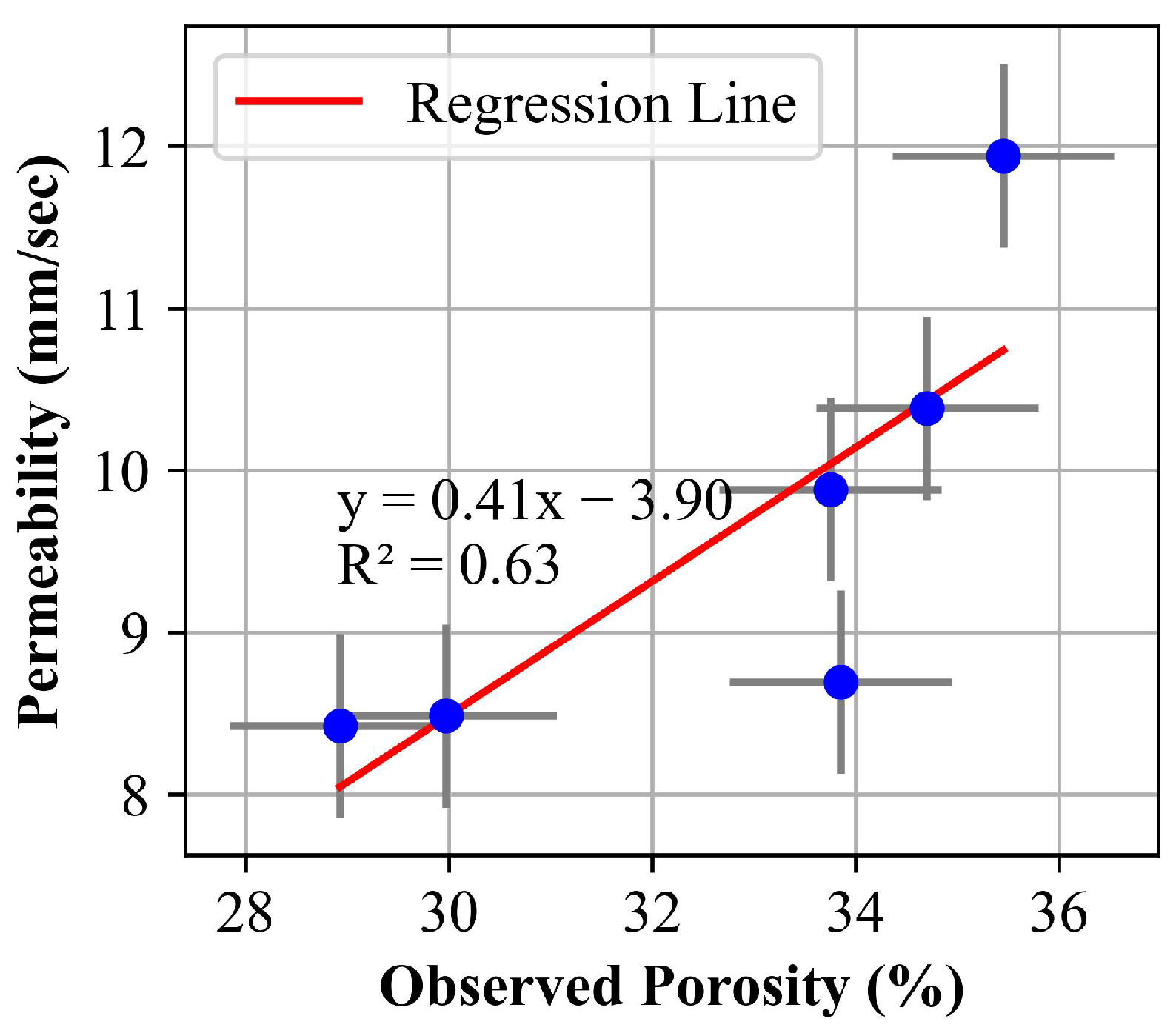
:This paper investigates porous concrete and the influence of water level variations and porosity on the mechanical, physical, and hydraulic properties of porous concrete. The effect of different void percentages and various water levels on the properties of porous concrete was studied. Fabricated specimens with targeted porosities of 20% and 25% were subjected to a series of tests to evaluate their compressive strength, hydraulic conductivity (permeability), and porosity. The permeability of the specimens was assessed using a falling head permeameter to ensure effective water percolation. Porosity was quantified through a volumetric method, providing insights into void content. Both cubical and cylindrical specimens were used for all tests, along with compression tests under both air-dried and oven-dried conditions. The results showed that the maximum compressive strength occurred under oven-dried conditions for both cubical (7.05 MPa, 5.58 MPa) and cylindrical (8.36 MPa, 4.81 MPa) specimens, with 20% and 25% porosities, respectively. The compressive strength was found to be low in air-dried samples and increased with higher water levels, peaking at the 40% water level. Furthermore, the porosity exhibited a significant correlation with the reduction in density, affecting the mechanical properties. For the cylindrical and cubical samples, the dry density decreased by 16.03 kg/m3 and 20.85 kg/m3 and the permeability increased by 0.41 mm/s and 0.84 mm/s, respectively, for every 1% increase in porosity. The results showcased the effect of water level variation on porous concrete properties as well as its promising ability to infiltrate water. This promotes the development of sustainable pavement systems by minimizing surface runoff and aiding groundwater recharge.
1. Introduction
The natural ground is being transformed into impermeable land cover, due to high-impact development in transportation infrastructure areas and caused by the construction of conventional pavements [1]. The use of conventional concrete induces alterations in the hydrological aspects and the thermal environment of the surroundings [2]. An increase in impermeable surfaces generally reduces hydrologic response time and therefore increases flood risk [3]. Urban expansion exacerbates stormwater runoff contamination due to impervious pavements, hindering clean water absorption into the soil and disrupting the natural water cycle [4]. Moreover, issues with hydroplaning surfaces, reduced groundwater recharge, and non-skid-resistant wearing courses are detrimental to impermeable pavement systems [1]. Additionally, urbanization has also increased construction and demolition waste, which is often discarded in landfills with limited reuse. Recycling this waste into construction material is a sustainable solution, curbing pollution and reducing reliance on finite resources. Porous concrete (PC) pavements have emerged as a promising low-impact development technology, as a way to reduce the negative environmental effects of infrastructure development and operation [5]. Utilizing strategies like using recycled concrete aggregate, which can be used in porous concrete, minimizes waste and natural resource usage, making porous concrete an environmentally advantageous solution for sustainable development [6].
Because of its porous structure, porous concrete offers numerous benefits for addressing urban issues such as urban heat islands, noise from transportation, urban waterlogging, and groundwater depletion [7]. Porous concrete pavements enable stormwater runoff to filter through surface voids, directing it into an underlying stone reservoir for storage and infiltration [8]. This pavement system allows easy retrofitting in dense urban areas, enabling on-site stormwater infiltration, without use of urban space [9]. It filters stormwater effectively, recharges groundwater, and reduces implementation costs [10]. Therefore, porous concrete is ideal for pavement systems, providing environmental protection and sustainability advantages [11]. Replacing just 6% of impervious surfaces with porous concrete pavements in areas where more than 80% of the surface is impermeable can mitigate the urban heat island effect, enhance architectural aesthetics, and reduce surface runoff, benefiting the stormwater system [12]. These pavements, which receive runoff from neighboring impervious surfaces and are situated above poorly drained soils, can play a crucial role in hydrologic mitigation [13].
PC is a non-slumping, open-graded material comprising hydraulic cement, coarse aggregate, admixtures, and water, with connected pores ranging from 2 to 8 mm, a void content typically between 15% and 35%, compressive strength of 2.8 MPa to 28 MPa, and a drainage rate of 81 to 730 L/Min/m2, depending on the size of the aggregates and mixture density [14]. Its primary characteristic lies in its elevated permeability attributed to a substantial void content, which imparts a light weight and lower strength when juxtaposed with conventional or waterproof concrete [15].
PC has been commonly used in permeable pavement systems such as roadways, sidewalks, driveways, parking lots, and other light-duty flatwork applications [16]. Studies have revealed that key factors influencing the strength of PC include the concrete porosity, water-to-cementitious material ratio, paste characteristics, as well as the size and volume content of coarse aggregates [17,18,19]. Achieving consistent compressive strength across different types and gradations of aggregates is feasible through careful mixture design [20]. An increase in porosity resulted in an increase in permeability and a simultaneous decrease in compressive strength [21]. The large and medium pores significantly contributed to the permeability of porous concrete, while adding cement enhanced the compressive strength by reducing porosity, minimizing small pores, and increasing hydration products [22].
The main objective of the implementation of porous concrete in road pavement systems is to percolate the rainfall water to recharge the groundwater system. During continuous rainfall, the subgrade soil becomes saturated, and the underground water recharge process is blocked. The voids in the porous concrete layer, which are approximately 20–25%, with the aggregate layer being approximately 35–40%, can serve as temporary water reservoirs by storing rainwater [23]. Over time, the water stored in these voids can slowly infiltrate the subsoil, contributing to groundwater recharge. A porous concrete pavement should be able to withstand vehicular loads and other relevant loads subjected to different water-level conditions. It is thus necessary to ensure the performance of a porous concrete pavement in different water-level conditions.
The mechanical and durability characteristics of concrete are significantly affected by the presence of water in its pores [24]. Excess water in concrete can lead to structural damage, including fractures and spalling [25]. The addition of fly ash to magnesium oxychloride cement enhances its pore structure, water repellency, and overall stability when exposed to water [26]. The molar ratios of the raw materials and the curing conditions in turn also have an impact on these parameters [27]. Evaluating the structural performance of these structures involves assessing their mechanical properties, particularly the compressive strength [28]. Research has been conducted on the effect of moisture variation relative to water saturation on the compressive strength of conventional concrete. It was found that the compressive strength of the concrete decreased as the moisture content increased [29]. The compressive strength of concrete decreased correspondingly with an increase in moisture content, but an unexpected rise in compressive strength was noticed at nearly saturated conditions [30]. The initial increase in moisture content led to a decrease in compressive strength, which then increased. Furthermore, the impact of moisture content on compressive strength intensified as porosity increased [31]. The mechanical properties of porous concrete may also be affected by variations in water levels within the pore structure, leading to changes in internal water content and stress distribution. Although the effect of water content variation on the compressive strength of concrete has been studied, the variation in the properties of porous concrete under different water level conditions remains unknown. Therefore, it is crucial to investigate the impact of water level variation on the mechanical properties of porous concrete under various loading conditions and environmental factors.
The objective of this study was to analyze the interplay of water level variation regarding the mechanical properties of porous concrete, along with the influence on hydraulic properties due to porosity. To investigate this relationship, standard practices were followed for material selection and sample preparation (cubical and cylindrical) in accordance with Indian Standards (IS) and ASTM (American Society for Testing and Materials) codes. The influence of porosity on hydraulic properties was assessed by calculating permeability using a falling head permeameter. Furthermore, to assess the impact of water level variations on the mechanical properties, compressive strength was determined using a universal testing machine (UTM) at simulated water table levels. The investigation then further explored the correlation between permeability and porosity, alongside the relationship between compressive strength and water level.
2. Experimental Programs
2.1. Materials
Type I Portland cement having a specific gravity of 3.15 and conforming to the requirements of ASTM C 150 [32] was used to prepare all the concrete mixtures. This type of cement is a general-purpose cement suitable for most concrete construction projects and commonly available on the market.
In the study, only a single group of aggregates, characterized by particle sizes ranging from those passing through a 10 mm sieve to those retained on a 4.75 mm sieve, was utilized. It was found that porous concrete containing smaller aggregate sizes exhibited superior strength, attributed to the increased total bond area between neighboring aggregates [33]. The physical properties of the coarse aggregates used are tabulated in Table 1.
2.2. Preparation of Specimens
The process of preparing porous concrete was a multi-step procedure that involved careful attention to detail and precise execution to achieve the desired porosity levels. The materials were initially collected and tested for properties like their specific gravity, bulk density, water absorption, ACV, AIV, and percentage of deleterious materials. The study incorporated ASTM C29 [34] standards to calculate the bulk density and voids in the aggregates. The sample was filled in three layers, with each layer receiving 25 tamping strokes as per ASTM C29 [34]. Target porosities of 20% and 25% were selected, considering the impermeability associated with porosities below 15% and the potential reduction in compressive strength at very high porosities (greater than 35%) as per American Concrete Institute (ACI) 522-R Report [14].
The porous concrete mix design was conducted in accordance with the guidelines set forth by ASTM C-192 code [35], ACI 522 R report [14] following the procedural recommendations outlined. The minimum volume of paste required for the mix was calculated using Equation (1) [36].
This calculation assumed that aggregates were compacted as in to the ASTM C29 (DRUW) procedure and that the paste component was relatively incompressible. Dry cement content was determined following the ACI 522 R-10 report [14], and judicious selection of a water-to-cement (w/c) ratio of 0.4 was made using a binder drainage test [37]. The material proportions for target porosities of 20% and 25% are shown in Table 2.
The coarse aggregate was accurately measured and combined with cement to produce a dry mix in a concrete mixer. The required amount of water was added to form a fresh concrete mix. This mixture was cast into molds in three layers and thoroughly consolidated by tamping with a tamping rod. Afterward, the molds were opened on the following day, and the specimens were subjected to a curing period of an additional 27 days to facilitate optimal hydration and strength development. The curing was performed in controlled lab conditions for the whole period at 23 °C ± 2°C, all following ASTM C192/C192M [35]. Table 3 presents the number of specimens used for the various tests, including permeability, porosity, and compressive strength tests. The compressive strength tests were conducted under different conditions, including air-drying, oven-drying, and varying water levels at 20%, 40%, 60%, 80%, and 100% of the specimen’s height for both 20% and 25% target void ratios.
For each specific target void ratio, a set comprising 24 cube specimens (150 mm × 150 mm × 150 mm) and 24 cylindrical specimens (diameter: 150 mm, height: 300 mm) were prepared. The choice of these specimen shapes was based on their established prominence and their widespread recommendation for evaluating the properties of concrete, as stipulated by the relevant standards such as IS 516-2021 Part 1 Section 1 [38] and ASTM code (ASTM C39/C39M) [39]. Within the sample pool, compressive strength assessments were conducted under various environmental conditions, encompassing oven-dried and air-dried states, as well as under different levels of specimen immersion, corresponding to water levels set at 20%, 40%, 60%, 80%, and 100% of the height of the specimen. Additionally, three samples were designated for each porosity level, to facilitate porosity and permeability calculations, as outlined in Table 3. This experimental setup adhered to the minimum sample specimen requirements prescribed by IS 456 (2000) [40] and ASTM C39 [39], ensuring statistical robustness and reliability in the analysis. The mix design proportion for each sample is shown in Table 4.
2.3. Testing Programs
The mechanical properties (compressive strength), physical properties (density), and hydraulic properties (porosity and permeability) of the porous concrete specimens were tested.
2.3.1. Compressive Strength
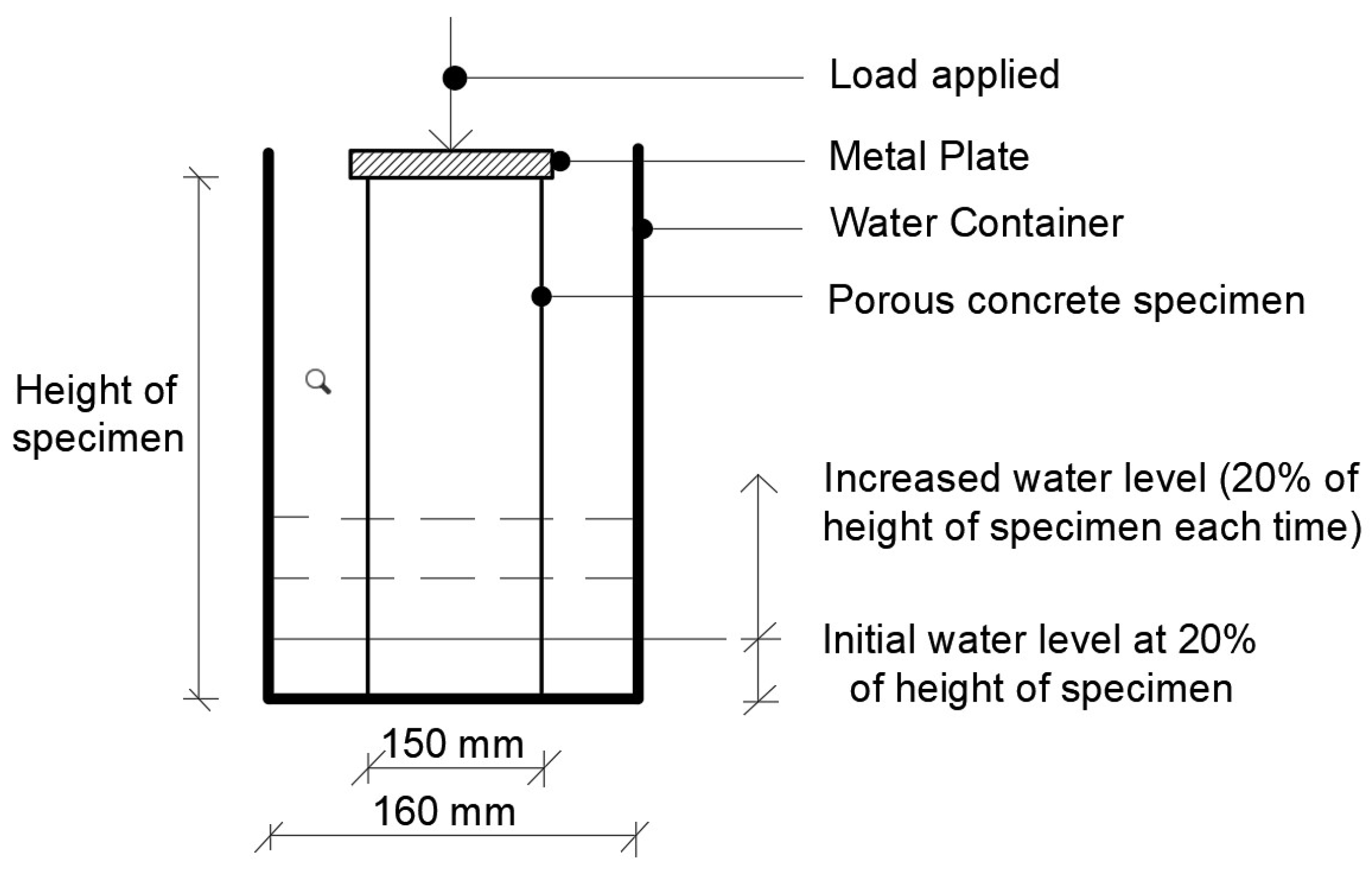
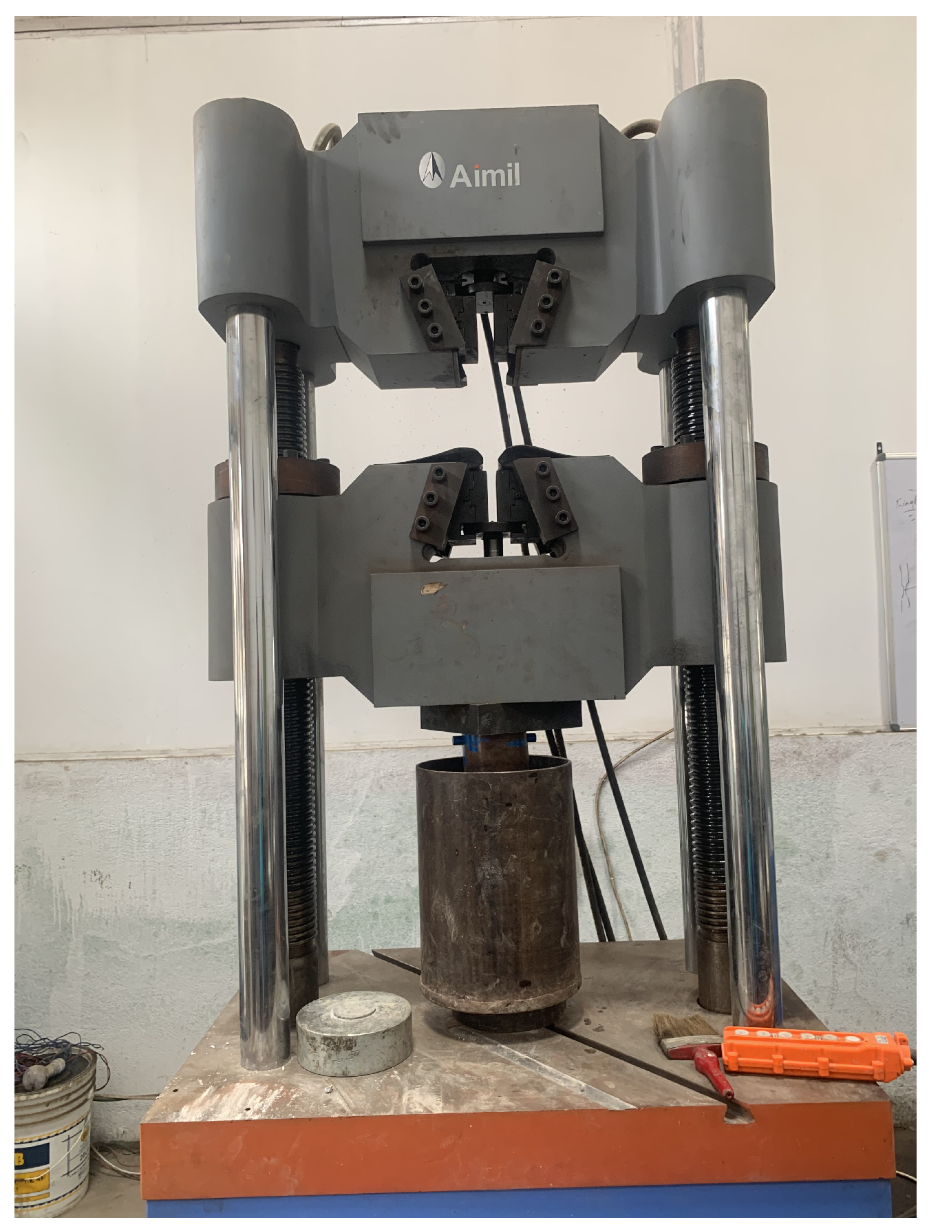
The mechanical properties, i.e., compressive strength tests, were conducted on specimens under different conditions: oven-dried, air-dried, and varying water levels (20%, 40%, 60%, 80%, and 100%). The oven-dried condition was checked as an ideal case for reference, the air-dried condition was checked to imitate regular field conditions, and the different water level conditions were checked to imitate different water table conditions in the field. After curing, the specimens were soaked for 24 h, air-dried for 24 h, or oven-dried for 24 h, as per the condition. Testing was performed using a compression machine, with soaked specimens placed in water containers at desired water levels, as shown in Figure 1. The compressive strength values were recorded following ASTM C39 [39] standards for all specimens. This involved subjecting the specimens to axial compressive loads at a controlled rate until failure occurred. The maximum load at failure was recorded, and the compressive strength was calculated by dividing this load by the cross-sectional area of the specimen.
2.3.2. Determination of Physical and Hydraulic Properties
The dry and the saturated surface dry (SSD) density were measured by dividing oven-dried weight by the volume of the specimen and SSD weight by the volume of the specimen, respectively [41].
The porosities of the PC specimen were determined from Equations (2)–(4), as shown below [42,43]. All three types of porosity were calculated for each sample.
where is the total porosity of the specimen and and are open and closed void ratios, respectively. is the weight of a specimen when it is submerged under water, is its weight in the SSD condition, and is the weight of the specimen after being totally dried in an oven. is the volume of the specimen, and is the density of water.
The coefficient of permeability for the specimens was determined using a custom-designed falling head permeameter, inspired by Neithalath [44]. The specimens were dried and laterally confined using wall putting and silicone to prevent water passage through the sides. The cube specimens had an acrylic sheet placed on top, as shown in Figure 4, while the cylinder specimens used a high-density polyethylene pipe secured with a rubber gasket and hose clamp, as shown in Figure 5. The prepared specimens were then placed in the permeability test apparatus.
Water was added to the tank until full, and the time taken for the water level to fall from fixed heights of 450 mm and 250 mm for cubes, and 650 mm and 450 mm for cylinders, was recorded. The coefficient of permeability (k) was calculated using Equation (5) [44,45].
where k is the coefficient of permeability, a is the cross-section area of the standpipe, A is the cross-section area of the sample, l is the length of the sample, and are initial and final heads, and t is the time for head fall.
3. Results
3.1. Influence of Water Table on Compressive Strength of Porous Concrete
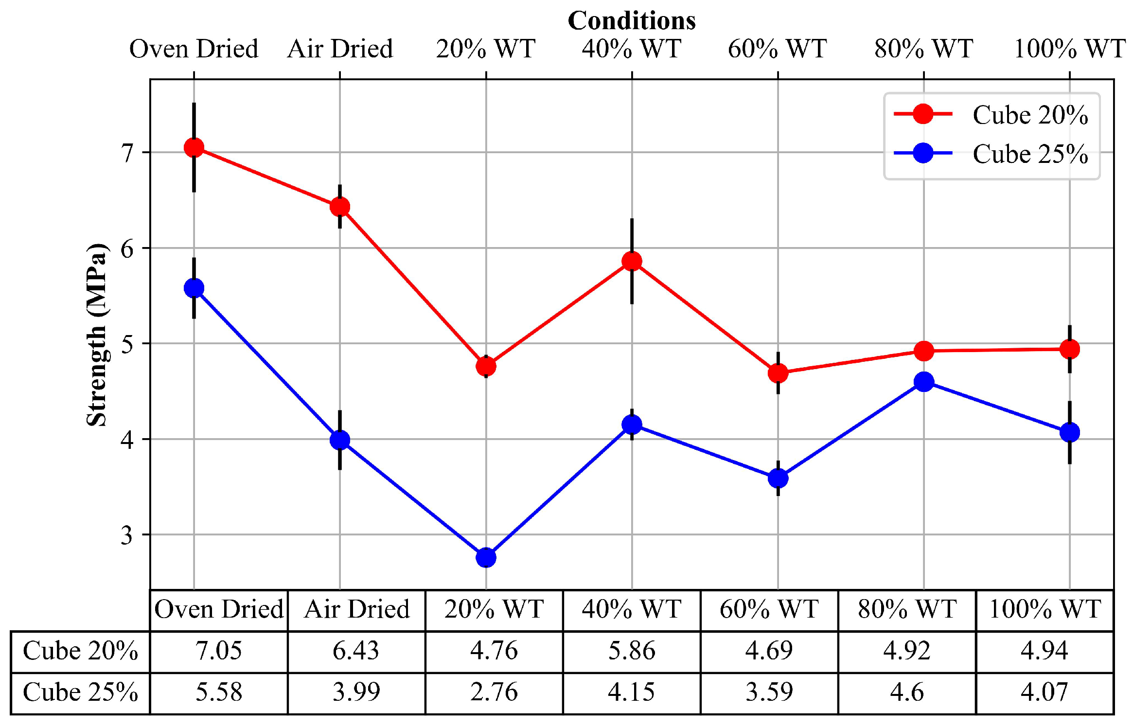
Figure 6 and Figure 7 show the compressive strength variation in the different test conditions for both cubical and cylindrical specimens under 20% and 25% void ratios. It can be seen from the graph that for both cylindrical and cubical specimens the oven-dried condition showed higher strength values compared to the air-dried condition. However, the strength of air-dried cylindrical sample for 25% void ratio was significantly lower (1.88 MPa). In the general case, it can be seen that the compressive strength decreased initially at the 20% water level, then peaking at the 40% (5.86 MPa, 4.16 MPa for cubes, 5.55 MPa, 4.91 MPa for cylinders) water level, excluding the air-dry and oven-dry conditions, followed by a gradual decrease and finally a slight increase in 100% water level, which was more profound in the cylindrical specimen rather than in the cubical specimen. While taking oven-dried samples as a reference, the maximum variation was 33.5% and 50.5% for cubical specimens, with 37.1% and 60.9% variations for the cylindrical specimens cast with 20% and 25% void contents, respectively. The least variation for the oven-dried samples was seen in the 40% water table conditions, which were 33.5% and −2.1% for the cylindrical specimens and 16.9% and 25.5% for the cubical specimens for 20% and 25% void ratios.
The decrease in the compressive strength of wet concrete may have been caused by the separation of cementitious particles using pore water, which might have reduced the van der Waals force and surface energy, thus reducing the critical stress of the cracks, which may have been the reason for the decrease in compressive strength of the samples at some water levels, as found in conventional concrete [29]. Notably, the compressive strength of the concrete at a 40% water content demonstrated a significant improvement, second only to the oven-dried sample. This may have been as, when concrete is subjected to a load, the pores and channels perpendicular to the load direction are closed, and free water flows inside the concrete. The viscosity of the water causes a pore water pressure gradient. Under a high loading rate, the pore water pressure increases, and the occurrence of cracks in the solid phase is delayed, thereby increasing the compressive strength of the concrete, as found in conventional concrete [46]. These reasons found in conventional concrete may also be applicable to porous concrete.
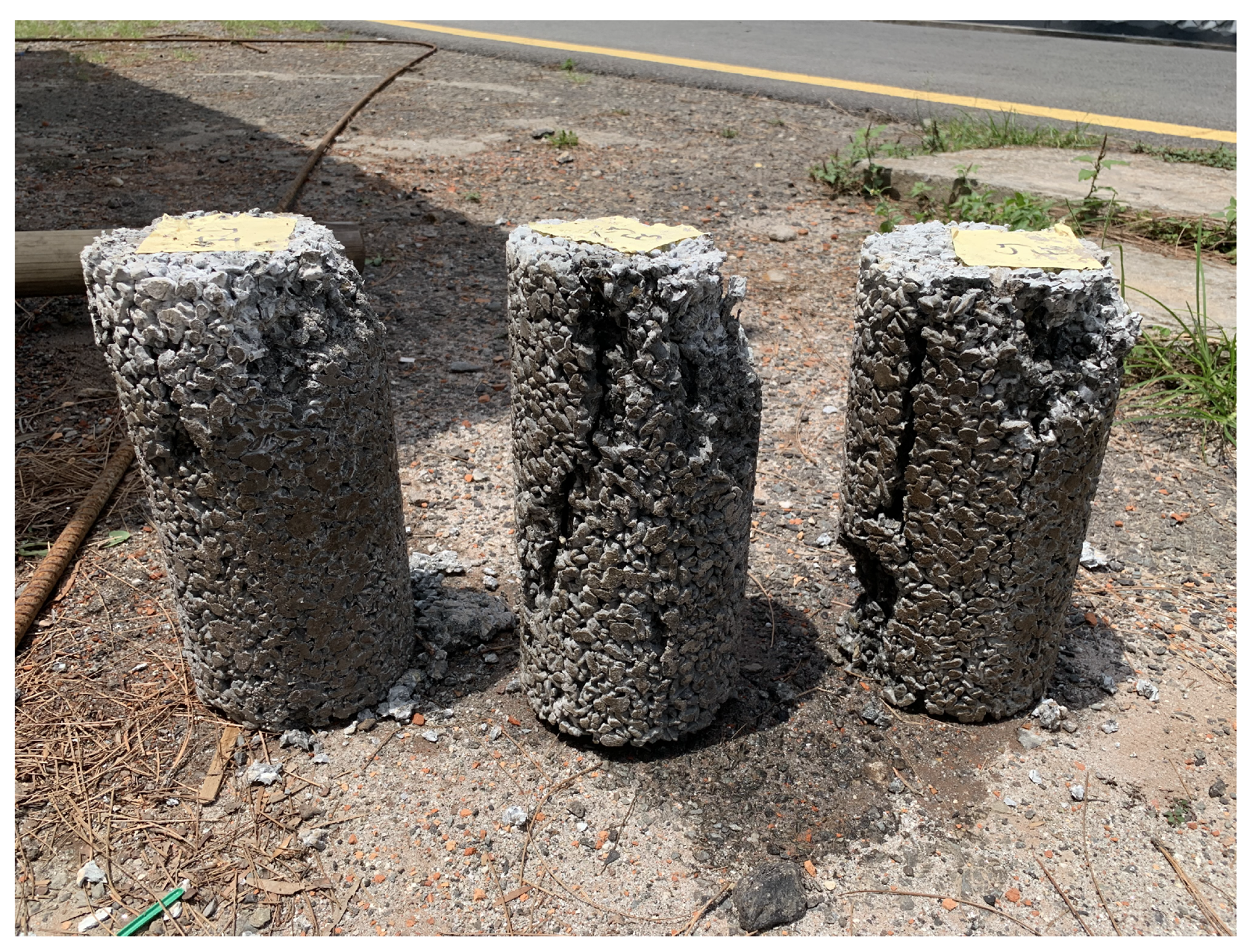
The analysis of the failure pattern revealed a predominant occurrence of specimen failure along the longitudinal sections, which aligned with the grooves formed during the compaction of concrete using a tamping rod. The observed failure pattern, as depicted in Figure 8 and Figure 9, offers valuable insights into the structural behavior of the porous concrete. Distinctly, the initial failure tended to manifest at the uppermost part of the specimens. This observed tendency can be ascribed to the distribution of compaction energy during the specimen fabrication process, where the top layer receive comparatively less compaction energy in comparison to the underlying layers.
3.2. Influence of Porosity on the Physical and Hydraulic Properties of the Porous Concrete
3.2.1. Density
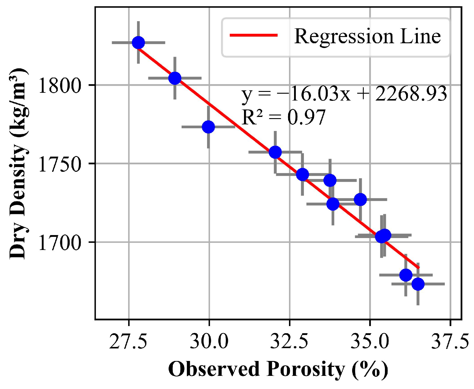
Upon a comprehensive examination of the data, it became evident that the augmentation in porosity exhibited a substantial correlation with the notable reduction in density. This decrease in density can predominantly be ascribed to the presence of a larger number of voids and an increased abundance of voids within the porous concrete, as visually depicted in the accompanying Figure 10 and Figure 11. Additionally, the decline in density was accompanied by a proportional deterioration in the material’s mechanical properties, particularly concerning the compressive strength, as demonstrated in Figure 6 and Figure 7.
3.2.2. Permeability
Similarly, Figure 12 and Figure 13 depict the relationship between the permeability of the porous concrete and its porosity. The data clearly illustrate that porosity exerted a direct influence on the permeability of the porous concrete, revealing a linear correlation. Specifically, as the porosity of the porous concrete increased, its permeability was proportionally augmented. This phenomenon can be rationalized by considering the increased presence of open voids within the porous structure as the porosity increases. Consequently, this amplified void space offers a larger surface area for water to permeate through the material.
3.2.3. Observed Porosity
The examination of porosity in the porous specimens unveiled differences between the intended and actual porosity values, as depicted in Table 5. The estimated porosity consistently manifested lower values compared to the observed porosity. These variations can be attributed to the compaction effort and type employed during the preparation of samples. Specifically, the hand compaction method was used, and the compaction effort, which was applied twenty-five times in three layers by different individuals, was not uniform across all specimens. This inconsistency in the compaction process led to variations in the density of the material, thereby affecting the porosity. As a result, the actual porosity values deviated from the intended values.
4. Conclusions
This study examined the impact of water table variations and porosity on the physical property of density, mechanical property of compressive strength, and hydraulic property of permeability of porous concrete. This included experiments such as compressive strength tests, falling head permeability tests, and porosity tests for both cubical and cylindrical samples with target void ratios of 20% and 25%. The conclusions presented here are based on the findings of this investigation. From the results obtained, the following conclusions may be drawn:
- The oven-dried condition resulted in the highest compressive strength for both cubical and cylindrical specimens. Compressive strength peaked at 40% water level and decreased at 60% due to cementitious particle separation by the pore water. A slight increase was observed at the 100% water level, possibly due to pore closure and free water flow.
- Increasing porosity led to a decrease in both density and compressive strength. This may be attributed to the presence of a larger number of voids, reducing the effective load-carrying area. The observed porosity values were consistently higher than the target porosities, due to compaction limitations.
- Porosity directly impacts the permeability of porous concrete, showing a linear correlation. Higher porosity leads to increased permeability due to the presence of more open voids, offering a larger surface area for water to infiltrate.
Overall, the different water level conditions in porous concrete showed significant changes in the compressive strength value. More such research works on microstructure pore structure analysis and its effect on mechanical properties need to be carried out to generalize the results. Understanding this relationship between compressive strength and the respective change in the water table is vital for effective implementation in sustainable pavement systems.
Author Contributions
Conceptualization, R.L. and T.B.K.; Formal Analysis, R.L., T.B.K. and S.P.; Methodology, R.L., T.B.K. and S.P.; Original Draft, R.L. and S.P.; Review, G.B.M., T.B.K., Y.X.Z. and P.P.; Edit, R.L., T.B.K., P.P. and S.P.; Supervision, G.B.M. and T.B.K. All authors have read and agreed to the published version of the manuscript.
Funding
This research was funded by Kathmandu Valley Water Supply Management Board through the Centre for Water Resources Studies, Institute of Engineering, Tribhuvan University (CWRS, IOE, TU).
Institutional Review Board Statement
Not applicable.
Informed Consent Statement
Informed consent was obtained from all subjects involved in the study.
Data Availability Statement
Data are contained within the article.
Acknowledgments
The authors extend their heartfelt gratitude and sincere appreciation to the Kathmandu Valley Water Supply Management Board for granting a fellowship to the first author of the article through the Centre for Water Resources Studies, Institute of Engineering, Tribhuvan University (CWRS, IOE, TU). Additionally, the authors are thankful to the staff of the Material Testing Laboratory at both Pulchowk Campus and Thapathali Campus, Faculty of Civil Engineering and Mechanical Engineering, for providing facilities and invaluable support during the experimental work.
Conflicts of Interest
The authors declare no conflicts of interest.
Abbreviations
The following abbreviations are used in this manuscript:
| ACI | American Concrete Institute |
| ACV | Aggregate Crushing Strength |
| AIV | Aggregate Impact Value |
| ASTM | American Society for Testing and Materials |
| IS | Indian Standard |
| PC | Porous Concrete |
| SSD | Saturated Surface Dry |
| UTM | Universal Testing Machine |
| w/c | water to cement ratio |
References
- Yang, J.; Jiang, G. Experimental study on properties of pervious concrete pavement materials. Cem. Concr. Res. 2003, 33, 381–386. [Google Scholar] [CrossRef]
- Volder, A.; Watson, T.; Viswanathan, B. Potential use of pervious concrete for maintaining existing mature trees during and after urban development. Urban For. Urban Green. 2009, 8, 249–256. [Google Scholar] [CrossRef]
- Feng, B.; Zhang, Y.; Bourke, R. Urbanization impacts on flood risks based on urban growth data and coupled flood models. Nat. Hazards 2021, 106, 613–627. [Google Scholar] [CrossRef]
- Zhang, K.; Bach, P.M.; Mathios, J.; Dotto, C.B.S.; Deletic, A. Quantifying the benefits of stormwater harvesting for pollution mitigation. Water Res. 2020, 171, 115395. [Google Scholar] [CrossRef] [PubMed]
- Moretti, L.; Di Mascio, P.; Fusco, C. Porous Concrete for Pedestrian Pavements. Water 2019, 11, 2105. [Google Scholar] [CrossRef]
- Muda, M.M.; Legese, A.M.; Urgessa, G.; Boja, T. Strength, Porosity and Permeability Properties of Porous Concrete Made from Recycled Concrete Aggregates. Constr. Mater. 2023, 3, 81–92. [Google Scholar] [CrossRef]
- Singh, A.; Sampath, P.V.; Biligiri, K.P. A review of sustainable pervious concrete systems: Emphasis on clogging, material characterization, and environmental aspects. Constr. Build. Mater. 2020, 261, 120491. [Google Scholar] [CrossRef]
- Trojan, M.D.; Gulliver, J.S.; Fairbairn, D.J. Groundwater Impacts from Stormwater Infiltration Practices. In Encyclopedia of Water; Wiley: Hoboken, NJ, USA, 2020; pp. 1–17. [Google Scholar]
- Zhang, K.; Yong, F.; McCarthy, D.T.; Deletic, A. Predicting long term removal of heavy metals from porous pavements for stormwater treatment. Water Res. 2018, 142, 236–245. [Google Scholar] [CrossRef] [PubMed]
- Alimohammadi, V.; Maghfouri, M.; Nourmohammadi, D.; Azarsa, P.; Gupta, R.; Saberian, M. Stormwater Runoff Treatment Using Pervious Concrete Modified with Various Nanomaterials: A Comprehensive Review. Sustainability 2021, 13, 8552. [Google Scholar] [CrossRef]
- Xie, N.; Akin, M.; Shi, X. Permeable concrete pavements: A review of environmental benefits and durability. J. Clean. Prod. 2019, 210, 1605–1621. [Google Scholar] [CrossRef]
- Rodak, C.M.; Jayakaran, A.D.; Moore, T.L.; David, R.; Rhodes, E.R.; Vogel, J.R. Urban stormwater characterization, control, and treatment. Water Environ. Res. 2020, 92, 1552–1586. [Google Scholar] [CrossRef] [PubMed]
- Tirpak, R.A.; Winston, R.J.; Feliciano, M.; Dorsey, J.D.; Epps, T.H. Impacts of permeable interlocking concrete pavement on the runoff hydrograph: Volume reduction, peak flow mitigation, and extension of lag times. Hydrol. Process. 2021, 35, e14167. [Google Scholar] [CrossRef]
- ACI Committee 522. Report on Pervious Concrete 522R-10; American Concrete Institute: Farmington Hills, MI, USA, 2010. [Google Scholar]
- Ibrahim, H.A.; Razak, H.A.; Abutaha, F. Strength and abrasion resistance of palm oil clinker pervious concrete under different curing method. Constr. Build. Mater. 2017, 147, 576–587. [Google Scholar] [CrossRef]
- Latif, A.A.; Putrajaya, R.; Ing, D.S. A Review of Porous Concrete Pavement: Compressive Strength and Clogging Investigation. J. Adv. Res. Appl. Sci. Eng. Technol. 2023, 29, 128–138. [Google Scholar]
- Chen, Y.; Wang, K.; Wang, X.; Zhou, W. Strength, fracture and fatigue of pervious concrete. Constr. Build. Mater. 2013, 42, 97–104. [Google Scholar] [CrossRef]
- Chindaprasirt, P.; Hatanaka, S.; Chareerat, T.; Mishima, N.; Yuasa, Y. Cement paste characteristics and porous concrete properties. Constr. Build. Mater. 2008, 22, 894–901. [Google Scholar] [CrossRef]
- Yu, F.; Sun, D.; Wang, J.; Hu, M. Influence of aggregate size on compressive strength of pervious concrete. Constr. Build. Mater. 2019, 209, 463–475. [Google Scholar] [CrossRef]
- Yavuz, D.; Yazıcı, Ş. Experimental study of aggregate size and gradation on pervious concretes’ mechanic, hydraulic, and surface properties. Struct. Concr. 2023, 24, 5451–5464. [Google Scholar] [CrossRef]
- Mahalingam, R.; Mahalingam, S.V. Analysis of pervious concrete properties. Gradjevinar 2016, 68, 493–501. [Google Scholar]
- Yu, F.; Guo, J.; Li, Z.; Huang, Y. Enhancing both strength and permeability of pervious concrete by optimizing pore structure: An experimental study. Struct. Concr. 2023, 24, 6251–6269. [Google Scholar] [CrossRef]
- Leming, M.L.; Malcom, H.R.; Tennis, P.D. Hydrologic Design of Pervious Concrete; Portland Cement Association: Skokie, IL, USA; National Ready Mixed Concrete Association: Silver Spring, MD, USA, 2007. [Google Scholar]
- Hover, K.C. The influence of water on the performance of concrete. Constr. Build. Mater. 2011, 25, 3003–3013. [Google Scholar] [CrossRef]
- Candelaria, M.D.E.; Kee, S.-H.; Yee, J.-J.; Lee, J.-W. Effects of Saturation Levels on the Ultrasonic Pulse Velocities and Mechanical Properties of Concrete. Materials 2020, 14, 152. [Google Scholar] [CrossRef] [PubMed]
- Guo, Y.; Zhang, Y.; Soe, K.; Hutchison, W.D.; Timmers, H.; Poblete, M.R. Effect of fly ash on mechanical properties of magnesium oxychloride cement under water attack. Struct. Concr. 2020, 21, 1181–1199. [Google Scholar] [CrossRef]
- Guo, Y.; Zhang, Y.; Soe, K.; Pulham, M. Recent development in magnesium oxychloride cement. Struct. Concr. 2018, 19, 1290–1300. [Google Scholar] [CrossRef]
- Vasanelli, E.; Colangiuli, D.; Calia, A.; Luprano, V.A.M. Estimating in situ concrete strength combining direct and indirect measures via cross validation procedure. Constr. Build. Mater. 2017, 151, 916–924. [Google Scholar] [CrossRef]
- Zhang, G.; Li, X.; Li, Z. Experimental Study on Static Mechanical Properties and Moisture Contents of Concrete Under Water Environment. Sustainability 2019, 11, 2962. [Google Scholar] [CrossRef]
- Chen, X.; Huang, W.; Zhou, J. Effect of moisture content on compressive and split tensile strength of concrete. Indian J. Eng. Mater. Sci. 2012, 19, 427–435. [Google Scholar]
- Shen, J.; Xu, Q. Effect of moisture content and porosity on compressive strength of concrete during drying at 105 °C. Constr. Build. Mater. 2019, 195, 19–27. [Google Scholar] [CrossRef]
- ASTM C150/C150M; Standard Specification for Portland Cement. ASTM International: West Conshohocken, PA, USA, 2020.
- Zhong, R.; Wille, K. Compression response of normal and high strength pervious concrete. Constr. Build. Mater. 2016, 109, 177–187. [Google Scholar] [CrossRef]
- ASTM C29/C29M; Standard Test Method for Bulk Density (“Unit Weight”) and Voids in Aggregate. ASTM International: West Conshohocken, PA, USA, 2016.
- ASTM C192/C192M; Standard Practice for Making and Curing Concrete Test Specimens in the Laboratory. ASTM International: West Conshohocken, PA, USA, 2006.
- Deo, O.; Neithalath, N. Compressive response of pervious concretes proportioned for desired porosities. Constr. Build. Mater. 2011, 25, 4181–4189. [Google Scholar] [CrossRef]
- Nguyen, D.H.; Sebaibi, N.; Boutouil, M.; Leleyter, L.; Baraud, F. A modified method for the design of pervious concrete mix. Constr. Build. Mater. 2014, 73, 271–282. [Google Scholar] [CrossRef]
- IS 516-2021 Part 1 Section 1; Hardened Concrete Methods of Test Part 1 Testing of Strength of Hardened Concrete Section 1 Compressive, Flexural and Split Tensile Strength (First Revision). Bureau of Indian Standards: New Delhi, India, 2021.
- ASTM C39/C39M; Standard Test Method for Compressive Strength of Cylindrical Concrete Specimens. ASTM International: West Conshohocken, PA, USA, 2014.
- IS 456-2000; Plain and Reinforced Concrete—Code of Practice (Fourth Revision). Bureau of Indian Standards: New Delhi, India, 2000.
- Neithalath, N.; Weiss, J.; Olek, J. Characterizing Enhanced Porosity Concrete using electrical impedance to predict acoustic and hydraulic performance. Cem. Concr. Res. 2006, 36, 2074–2085. [Google Scholar] [CrossRef]
- Bhutta, A.R.; Hasanah, N.; Farhayu, N.; Hussin, M.W.; Tahir, M.B.M.; Mirza, J. Properties of porous concrete from waste crushed concrete (recycled aggregate). Constr. Build. Mater. 2013, 47, 1243–1248. [Google Scholar] [CrossRef]
- Kim, H.K.; Lee, H.K. Influence of cement flow and aggregate type on the mechanical and acoustic characteristics of porous concrete. Appl. Acoust. 2010, 71, 607–615. [Google Scholar] [CrossRef]
- Neithalath, N.; Weiss, J.; Olek, J. Development of Quiet and Durable Porous Portland Cement Concrete Paving Materials. 2003. Available online: https://rosap.ntl.bts.gov/view/dot/16086 (accessed on 20 March 2023).
- Yuan, Y.; Chi, Y. Water permeability of concrete under uniaxial tension. Struct. Concr. 2014, 15, 191–201. [Google Scholar] [CrossRef]
- Wang, J.; Sun, K.; Hu, Y.; Guan, Q.; Li, Q. The mechanical properties of concrete in water environment: A review. Front. Mater. 2022, 9, 996650. [Google Scholar] [CrossRef]
Figure 1.
Specimen arrangement for compressive strength testing at different water levels.

Figure 2.
Compressive strength testing of cylindrical specimens with water container using UTM.

Figure 3.
Compressive strength testing of cubical specimens with water container using a UTM.
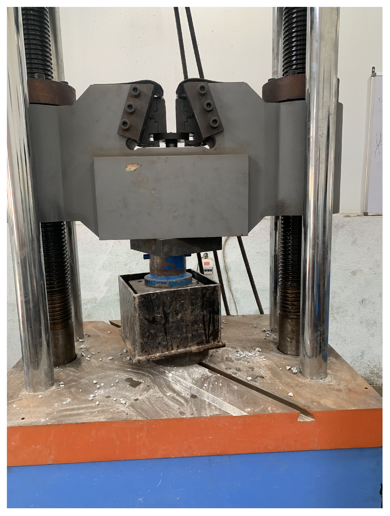
Figure 4.
Permeability measurement apparatus for cubical specimen.
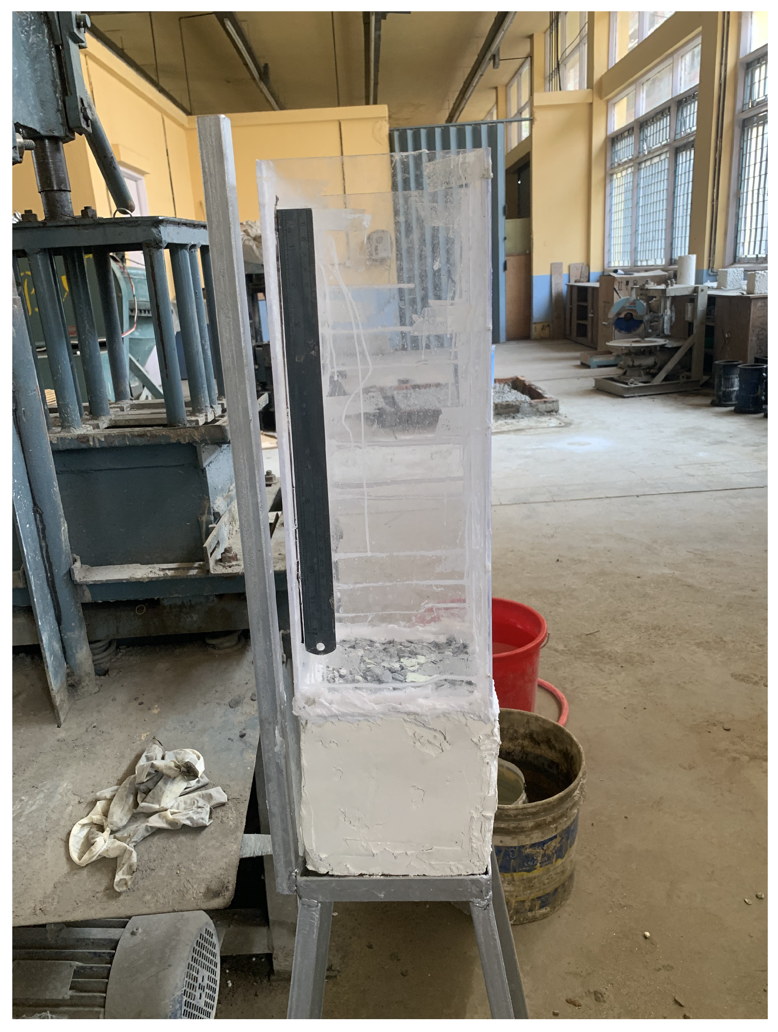
Figure 5.
Permeability measurement apparatus for cylindrical specimen.
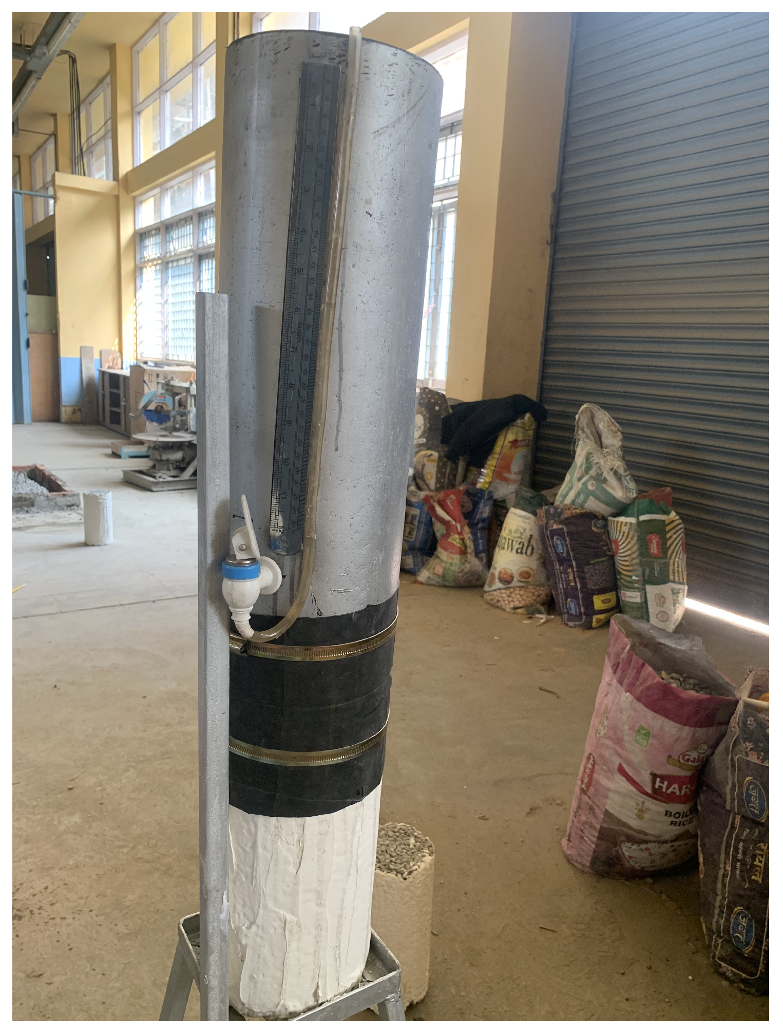
Figure 6.
Plot of compressive strength of cubes in different test conditions.

Figure 7.
Plot of compressive strength of cylinder in different test conditions.
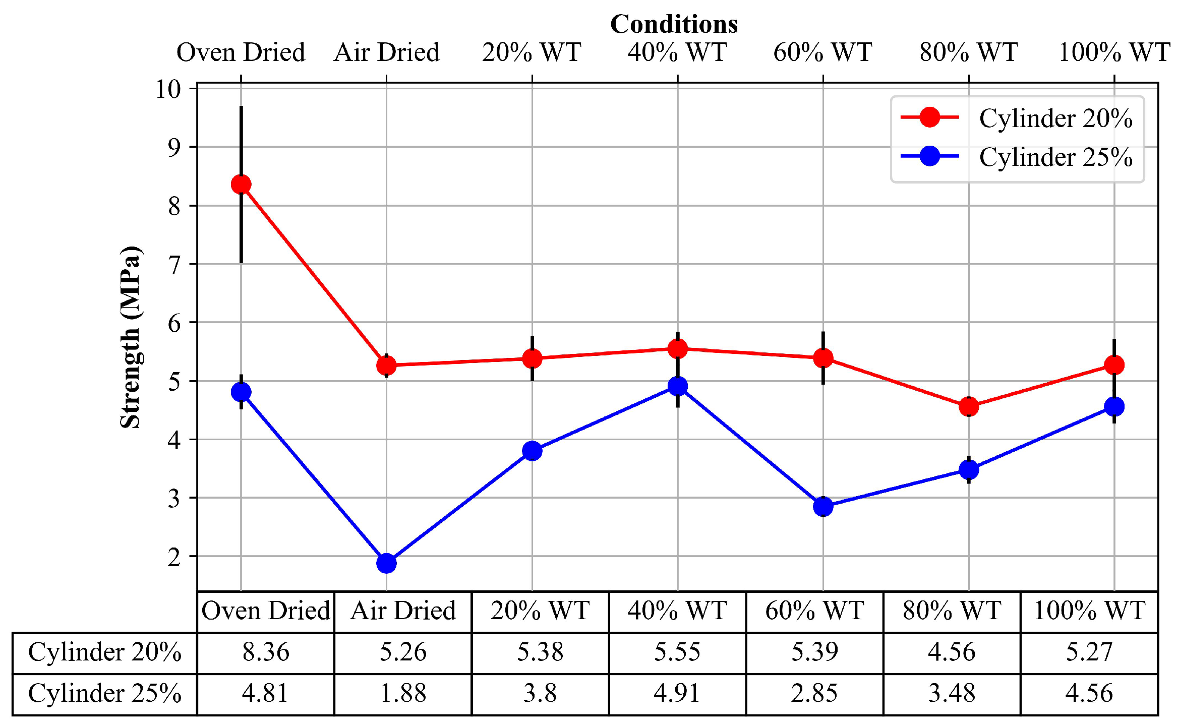
Figure 8.
Failure pattern for cubical specimens.
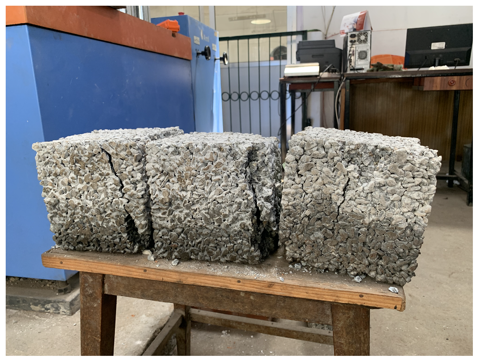
Figure 9.
Failure pattern for cylindrical specimens.

Figure 10.
Plot of density vs. observed porosity for cubes.
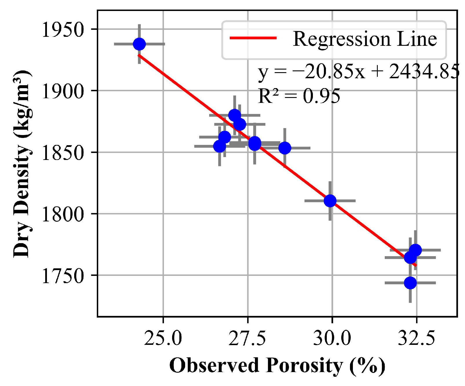
Figure 11.
Plot of density vs. observed porosity for cylinders.

Figure 12.
Plot of permeability vs. porosity for cubes.
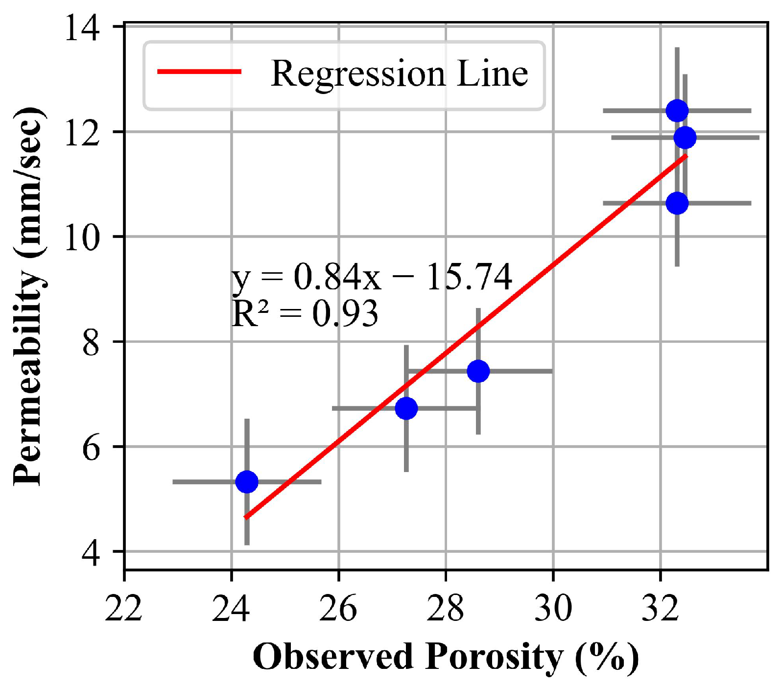
Figure 13.
Plot of permeability vs. porosity for cylinders.

Table 1.
Physical properties of coarse aggregates.
| Aggregate Size | 10 mm–4.75 mm |
| Sp. Gr | 2.64 |
| Bulk Density | 1542.57 kg/m3 |
| Water Absorption | 0.868% |
| Percentage of Deleterious Materials | 4.702% |
| Aggregate Impact Value (AIV) | 35.40% |
| Aggregate Crushing Value (ACV) | 37.39% |
| Void Percentage | 41.50% |
Table 2.
Material proportions.
| Description | Design Data-20% Porosity | Design Data-25% Porosity | Remarks |
|---|---|---|---|
| Percentage of Aggregates Voids () | 41.50 | 41.50 | (ASTM C29/C29M) [34] |
| Adopted % of Void () | 20.00 | 25.00 | |
| Cement Paste () | 21.50 | 16.50 | |
| Specific Gravity of Cement | 0.32 | 0.32 | |
| Adopted w/c considering workability | 0.40 | 0.40 | |
| Cement Content () kg/m3 | 300.70 | 230.77 | (ACI Committee 522, 2010) [14] |
| Water Content (kg/m3) | 120.28 | 92.30 | |
| Coarse Aggregate (kg/m3) | 1542.57 | 1542.57 |
Table 3.
Number of specimens for different types of tests.
| Type of Test | No. of Cube Specimens (150 mm × 150 mm × 150 mm) | Number of Cylindrical Specimens (150 mm × 300 mm) |
|---|---|---|
| Compressive Strength Test | 21 | 21 |
| Normal Condition | ||
| Oven Dried Condition | ||
| Water Level at 20% of height | ||
| Water Level at 40% of height | ||
| Water Level at 60% of height | ||
| Water Level at 80% of height | ||
| Water Level at 100% of height | ||
| Porosity and Permeability | 3 | 3 |
| Normal Condition |
Table 4.
Mix proportions and w/c ratio for each void percentage.
| Sample | Mix Proportion (Cement: Aggregate) | w/c Ratio | Void Percentages |
|---|---|---|---|
| 1:5.13 | 0.4 | 20% | |
| 1:6.69 | 0.4 | 25% | |
Table 5.
Observed porosity for different target porosities.
| Target Porosity (%) | Observed Porosity Cylinder (%) | Observed Porosity Cube (%) |
|---|---|---|
| 28.93 | 24.29 | |
| 20 | 29.97 | 27.26 |
| 33.85 | 28.6 | |
| 33.75 | 32.31 | |
| 25 | 34.698 | 32.31 |
| 35.45 | 32.46 |
Disclaimer/Publisher’s Note: The statements, opinions and data contained in all publications are solely those of the individual author(s) and contributor(s) and not of MDPI and/or the editor(s). MDPI and/or the editor(s) disclaim responsibility for any injury to people or property resulting from any ideas, methods, instructions or products referred to in the content. |
© 2024 by the authors. Licensee MDPI, Basel, Switzerland. This article is an open access article distributed under the terms and conditions of the Creative Commons Attribution (CC BY) license (https://creativecommons.org/licenses/by/4.0/).
Share and Cite
MDPI and ACS Style
Lamichhane, R.; Motra, G.B.; Khadka, T.B.; Zhang, Y.X.; Pathak, P.; Pandit, S. Impact of Water Level Variation on Mechanical Properties of Porous Concrete. Sustainability 2024, 16, 3546. https://doi.org/10.3390/su16093546
AMA Style
Lamichhane R, Motra GB, Khadka TB, Zhang YX, Pathak P, Pandit S. Impact of Water Level Variation on Mechanical Properties of Porous Concrete. Sustainability. 2024; 16(9):3546. https://doi.org/10.3390/su16093546
Chicago/Turabian StyleLamichhane, Rabin, Gokarna Bahadur Motra, Thaman Bahadur Khadka, Y. X. Zhang, Prabin Pathak, and Shikhar Pandit. 2024. "Impact of Water Level Variation on Mechanical Properties of Porous Concrete" Sustainability 16, no. 9: 3546. https://doi.org/10.3390/su16093546
Note that from the first issue of 2016, this journal uses article numbers instead of page numbers. See further details here.