1. Introduction
Urban underground space refers to the building space below urban development, including urban underground shelters, underground spaces, underground parking lots, and so on. Many of these underground spaces are aging and suffer from neglect and lack of maintenance. Moreover, the cyclic dynamic load from vehicles above ground poses a serious threat, often resulting in ground collapsing, endangering lives and property [
1,
2,
3,
4].
The safety of old urban underground space and the prevention of ground collapse have become major livelihood and development projects and have been highly valued by various countries [
5,
6,
7]. In light of the imperative for sustainable development, it is crucial to underscore the significance of adopting sustainable practices in the management and rehabilitation of old urban underground spaces. Identifying the physical field variations law of old urban underground spaces and correctly understanding the mechanisms are of great significance for the design and repair of old urban underground spaces.
The instability and failure of underground space structures can be attributed to factors such as seepage and cyclic load. Seepage-related damage includes soil piping and falls in water level. Several studies have investigated these phenomena and have revealed the impact on subsurface structures. For instance, Song [
8] studied the seepage effect on soil arching in a shield tunnel and proposed that seepage leads to an increase in effective vertical stress and weakens the soil arching effect. Attard [
9] studied the influence of underground structures on groundwater temperature and showed that underground structures and groundwater interact with each other. Di [
10] evaluated hydraulic head distribution in front of a shield tunnel in a saturated soil layer, and relative theoretical analysis and numerical simulations were carried out. The study revealed dynamic changes in the permeability field and provided important hydrogeological information to help prevent and control water-related problems in underground structures. By using the equivalent continuum model, Sheng [
11] conducted studies on the seepage and mechanical characteristics and carried out coupling calculations on the seepage field and stress field of the underground powerhouse caverns of Xiluodu Hydropower Station. The study illustrated the importance of the interaction of water flow and stress fields and proposed that the coupled effects of infiltration and stress in geotechnical engineering practice should be considered.
The impact of traffic cyclic load on underground spaces primarily manifests in four key aspects: vertical pressure, horizontal force, the influence of long-term cyclic load, and shock effects [
12,
13,
14,
15,
16]. Daehyeon [
17] utilized the finite element software ABQUS to investigate the dynamic response of a single tire on the road surface and provided valuable insights into the interaction between the tire and road surface. Saad [
18] used the finite element software ADINA to model subgrade of different materials and made a comparative analysis of the maximum compressive strain at the top and maximum tensile strain at the bottom of the subgrade at a speed of 50 km/h. This provided a reference for studying the influence of different roadbed materials on vehicle running. Additionally, Wu [
19] regarded vehicle-mounted vehicles as non-uniformly distributed moving loads. By establishing a three-dimensional transient dynamic finite element model, time-history variation rules and spatial distribution rules of road dynamic response under moving loads were analyzed, which provided a comprehensive perspective for vehicle motion characteristics under different road conditions.
In July 2023, Beijing experienced an exceptionally heavy rainstorm. Changes in groundwater and traffic loads have a significant effect on underground structures. As an important form of underground space, civil air defense engineering develops the important functions of a wartime air defense command center, communication center, hiding place, and so on. However, civil air defense structures are predominantly underground, rendering them vulnerable to the impacts of both traffic load and groundwater fluctuations and presenting intricate challenges to their structural integrity and stability. Currently, many civil air defense tunnels have incurred extensive damage, necessitating significant costs for repair and maintenance. According to related surveys, most civil air defense tunnels have not yet reached the overall fatigue resistance of the structure when damaged.
Many researchers have investigated and analyzed this phenomenon and found that there are many reasons for early damage in civil air defense engineering, among which some of the principal reasons are seepage and cyclic loads [
20,
21,
22,
23]. The current research mainly focuses on seepage and traffic loads and roads, as well as the effect of speed on road surfaces [
24,
25,
26,
27]. As structures situated underground, significant damage to civil air defense tunnels can lead to ground subsidence [
28,
29]. Li [
30] summarized research on the dynamic characteristics and constitutive models of soil under long-term cyclic loads and pointed out that long-term vibration loads have a significant impact on the performance of geotechnical engineering structures. Cao [
31] provided an analytical solution to study the impact of surface moving loads on underground tunnels, which is used to calculate the vibration generated by moving loads above circular tunnels.
Despite the known impacts of seepage and cyclic loads, the coupling effects of these factors on the physical field of old civil air defense engineering remain poorly understood. Current studies about civil air defense engineering do not consider the coupling disturbance of seepage and traffic cyclic loads, and the effect of seepage–traffic cyclic loads on old civil air defense engineering has not been mentioned. Therefore, this paper mainly focuses on the physical field of seepage–cyclic load coupling disturbance on civil air defense structures, providing a theoretical basis for the safe operation and maintenance of cities.
In this paper, the effect of seepage–cyclic load coupling disturbance on the physical field of old civil air defense engineering was studied. Firstly, from a case study of underground civil air defense engineering in Beijing, the primary size and burial depth of the tunnels was determined through field visits and investigations. Then, leveraging this information, the finite element software Plaxis 3D was used to simulate alterations in the physical field of the underground space under varying groundwater seepage conditions. Subsequently, dynamic responses of the underground space were calculated, taking into account the coupling effect of seepage and cyclic loads. The effect factors, such as the quantity and intersection state of tunnels, the location of rivers, and the rate of water table decline were investigated as well. This study can provide a sustainability development basis for the design, maintenance, and engineering management of underground spaces, which can enhance the resilience and longevity of underground structures.
3. Numerical Calculation
3.1. Plaxis 3D
The actual conditions were simulated using Plaxis 3D numerical calculation software. Plaxis 3D is a finite element software developed in the Netherlands for professional geotechnical engineering. It has strong applicability and can simulate complex geological engineering conditions, and it is especially suitable for deformation and stability analysis. It can analyze deformation, consolidation, graded loading, stability analysis, seepage calculation, and the influence of low-frequency dynamic loads can also be considered. The operating interface is user-friendly.
3.2. Seepage Finite Element Calculation of Underground Civil Air Defense Tunnels
(1) Case arrangement
The variation in urban groundwater level presents obvious seasonal characteristics. During the rainy season, groundwater level will rise, and it will decrease in the dry season. The sudden rise and fall of the groundwater level will cause significant changes in the effective stress of the soil, which will affect the soil around civil air defense engineering works. In order to study the seepage effect, in this section, the influence of tunnel type, tunnel arrangement, intersection of tunnels, and change of groundwater level on the civil air defense tunnels under the river is considered.
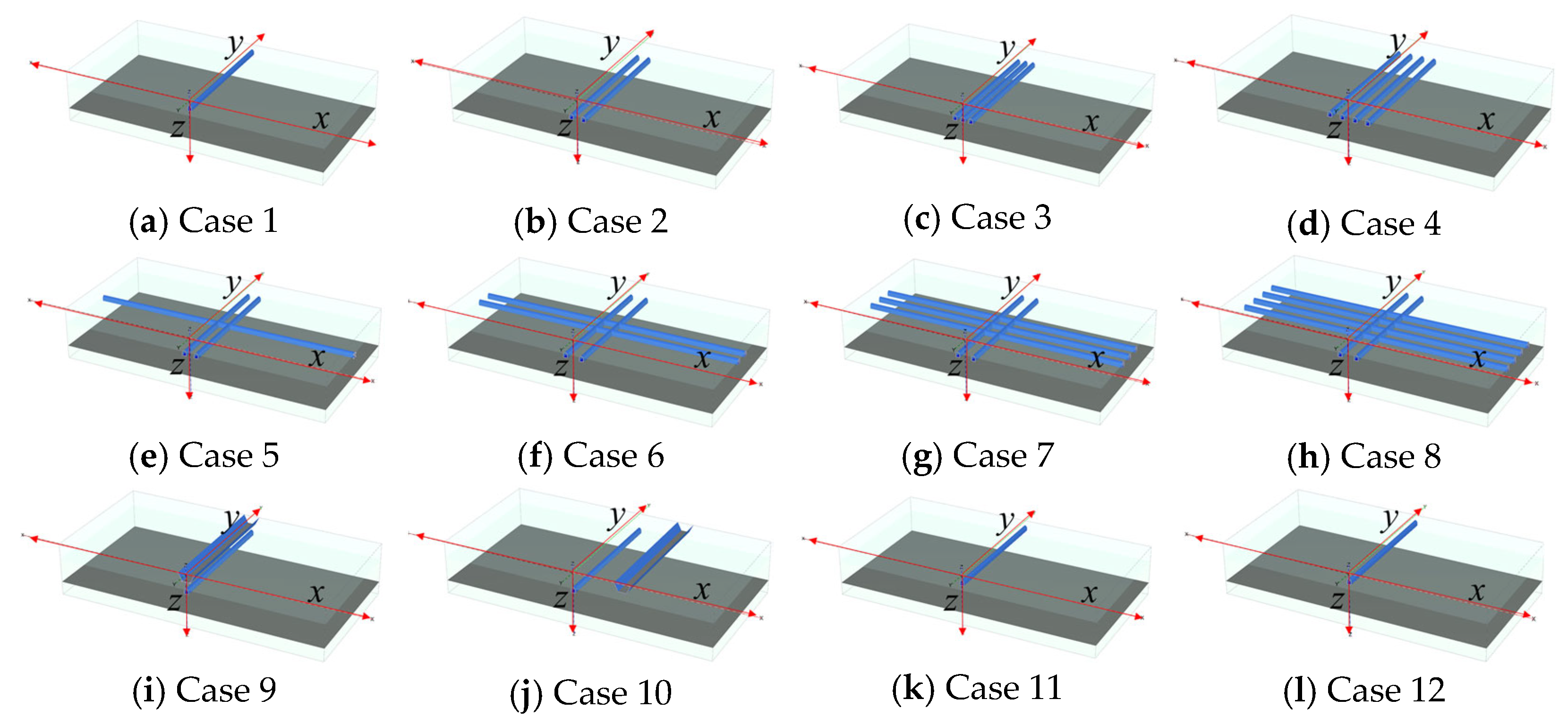
The cases are listed in
Table 2. Cases 1–4 relate to the influence of the quantity of tunnels, cases 5–8 relate to the increase in number of intersections of tunnels, cases 9–11 relate to the influence of the location of the river, and cases 12–13 relate to the decrease in strength of tunnel materials. In the River column, lack of an entry means the river does not exist in the corresponding model. In the selection of material strength data, the 70% value represents a condition where the material is under a moderate level of stress, which is common in many engineering situations. On the other hand, the 40% value represents a lower stress level, which is relevant to material degradation and aging. The various case stereograms are shown in
Figure 3.
In the Plaxis model, in order to avoid boundary effects, the model size is set as xmin = −50 m, xmax = 50 m, ymin = 0, ymax = 50 m. In the seepage calculation, the boundary condition of x and y is set as normally fixed. The bottom surface of the model is full-fixed, and the top surface is free. The material model adopts the Mohr–Coulomb law, and the type is drainage. The model adopts the Van Genuchten model. In the calculation of cyclic loads, the boundary condition of x and y is viscous. The bottom surface is full-fixed, and the top surface is free.
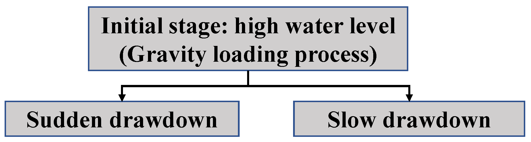
(2) Calculation phase settings
The change in groundwater level can be categorized into multiple stages. When the rainy season ends or groundwater is pumped in large quantities, the water level will decrease. Therefore, two calculation phases were set: (1) sudden drawdown of groundwater; (2) slow drawdown of groundwater. The highest water level is 15 m underground, and the lowest water level is 18 m underground. During the sudden drawdown phase, the water level falls at a rate of 0.8 m/day, whereas during the slow drawdown phase, the rate reduces to 0.1 m/day. The process for the calculation phases is depicted in
Figure 4.
3.3. Seepage–Traffic Load Coupling Disturbance Calculation
On the basis of the seepage calculation, this section applies traffic loads to calculate the displacement under the coupling effect of seepage–traffic cycle loads.
(1) Traffic cycle loads
Due to the vibration of the vehicle and the unevenness of the road surface during driving, the load will be applied on the road surface in the form of waves [
33,
34]. Since the sinusoidal load model is both practical and representative of actual engineering conditions, it is commonly employed by scholars to simulate vehicle loads [
35,
36]. The load can be described as
in which
P0 is the vehicle static load (20 kN for small cars and 100 kN for large cars); ω is the vibration frequency of the vehicle load (
ω = 2
πv/
L);
v is the driving speed;
L is the car length, referring to JTGB 01-2014 Highway Engineering Technical Standard [
37], where
L is 6 m;
P is the amplitude of vehicle load, where
,
M0 = 120 N·s
2/m, α = 2 m.
Based on the actual driving characteristics of the vehicle, three vehicle speeds were considered: 20 km/h, 60 km/h, 100 km/h, namely F
1, F
2, F
3.
Table 3 lists the relationship between vehicle speed and parameters of the sinusoidal load model. The dynamic multiplier is shown in
Figure 5a, and the cycle load is shown in
Figure 5b.
(2) Case setting
On the basis of the seepage calculation, various factors were considered, including tunnel type, quantity of tunnels, tunnel intersections, distance from the river, and changes in material parameters. The cases are listed in
Table 4. The various case stereograms are shown in
Figure 6.
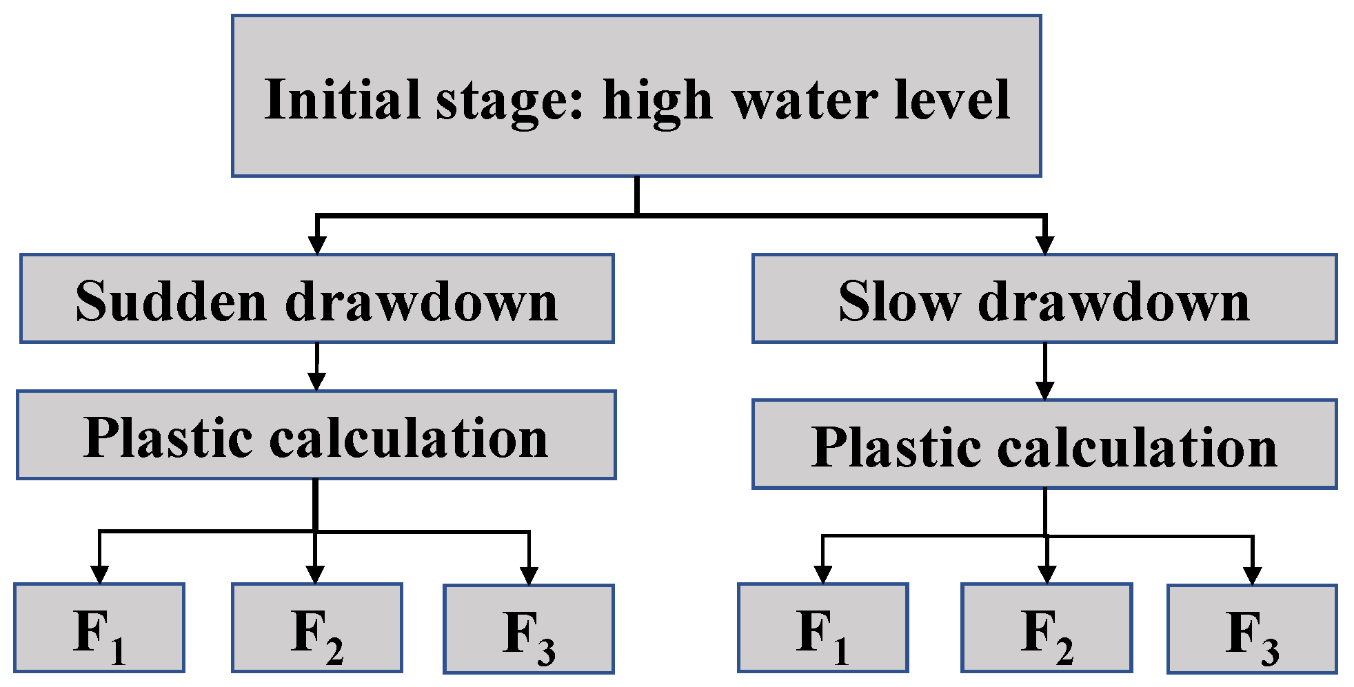
(3) Calculation phase settings
Based on the seepage calculation, the impact of traffic loads was calculated. The action time of traffic loads was set as 36,000 s. Each model was calculated under different load frequencies, as shown in
Figure 7.
4. Analysis of Calculation Results
According to the above cases, the calculation is divided into two stages. The first stage is to calculate the impact of seepage on civil air defense engineering. In the second stage, the displacement changes of civil air defense tunnels are considered after accounting for both traffic loads and seepage effects.
4.1. The Seepage Calculation of Old Civil Air Defense Engineering
The overall displacement of tunnel A under sudden drawdown and slow drawdown of groundwater level is shown in
Figure 8 and
Figure 9. In
Figure 8 and
Figure 9, it is evident that there are significant changes in displacement. According to the field visit and observation, it was found that certain ground settlement had occurred. The calculation results of the model are consistent with the observed trend, including the performance data of existing tunnels and the amount of ground settlement. This indicates that the calculation of this model is reasonable.
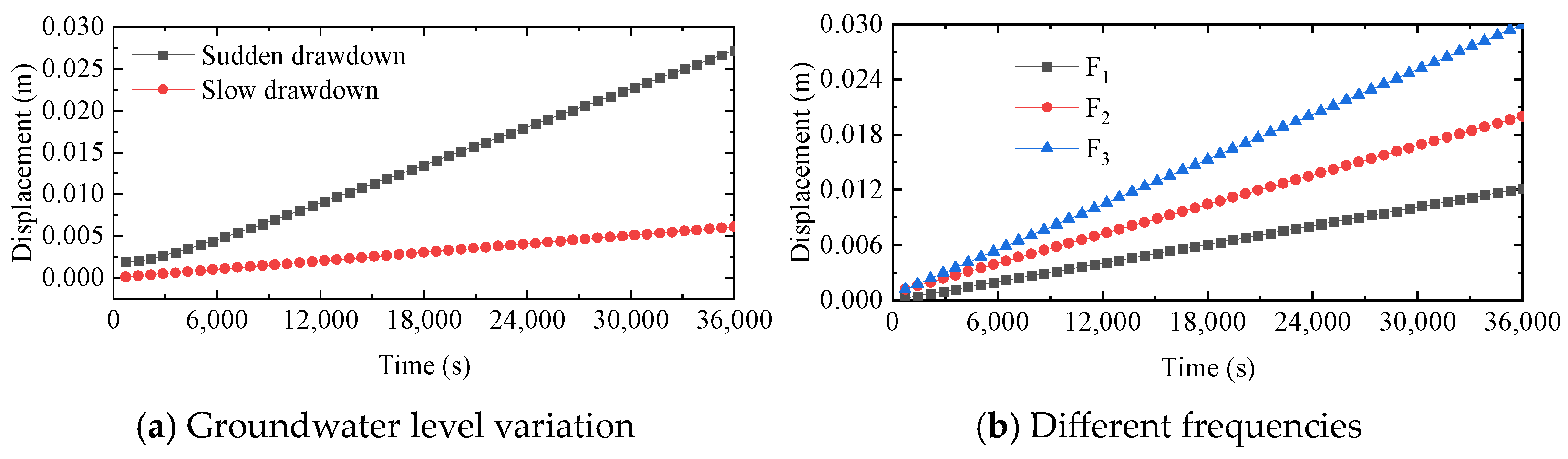
The displacement of the ground center point under different conditions is presented in
Figure 10. In
Figure 10, it can be seen that the ground displacement caused by sudden drawdown of groundwater is always higher than that caused by slow drawdown. With respect to the quantity of tunnels, as the quantity of tunnels increases, the ground displacement increases after groundwater changes. With respect to the intersection of tunnels, it can be seen that as the quantity of tunnel intersections increases, the ground displacement also increases. Regarding the location of rivers, the smaller the horizontal distance of the tunnel from the river, the greater the displacement of the tunnel chamber and its surroundings. Regarding groundwater level changes, the presence of rivers leads to significant infiltration effects around the tunnels, and the impact of groundwater level changes is weakened. With respect to the material strength changes, under the seepage effect, the lower the material strength, the higher the ground displacement. Regarding the type of tunnel, the ground displacement of tunnel B under seepage is smaller than that of tunnel A.
To express the influence of factors on surface displacements clearly, based on the above results, the relationships between the influencing factors and surface displacements are summarized in
Table 5.
When the water level drops rapidly, the force balance of the soil layer will be disrupted, and the effective stress changes rapidly, causing the ground to sink, which is detrimental to the civil air defense tunnel. When the quantity of tunnels increases, the underground space increases and support decreases, making it more likely to cause ground collapse, which is also detrimental to the structure. Similarly, an increase in tunnel intersections diminishes the stiffness of the intersection area, exacerbating tunnel and surface displacement under seepage effects, thus affecting structural stability. With the seepage effect, the displacement of the tunnel and surface is greater than that of a single tunnel intersection. When there is a river near the tunnels, the seepage effect of the river is significant, and the impact of groundwater changes will be weakened. Furthermore, when tunnel material strength decreases, the ground displacement caused by seepage is the greatest, indicating that the decrease in material strength under seepage has a significant impact on ground displacement, far worse than the impact of tunnel layout, and is the most detrimental for civil air defense tunnels.
Based on a comprehensive analysis, the weakening of the material strength of the tunnel is most sensitive to the effect of seepage, and displacement of the ground is the largest. In practical engineering, special attention should be paid to old civil air defense tunnels to avoid accidents such as collapse caused by groundwater or river seepage.
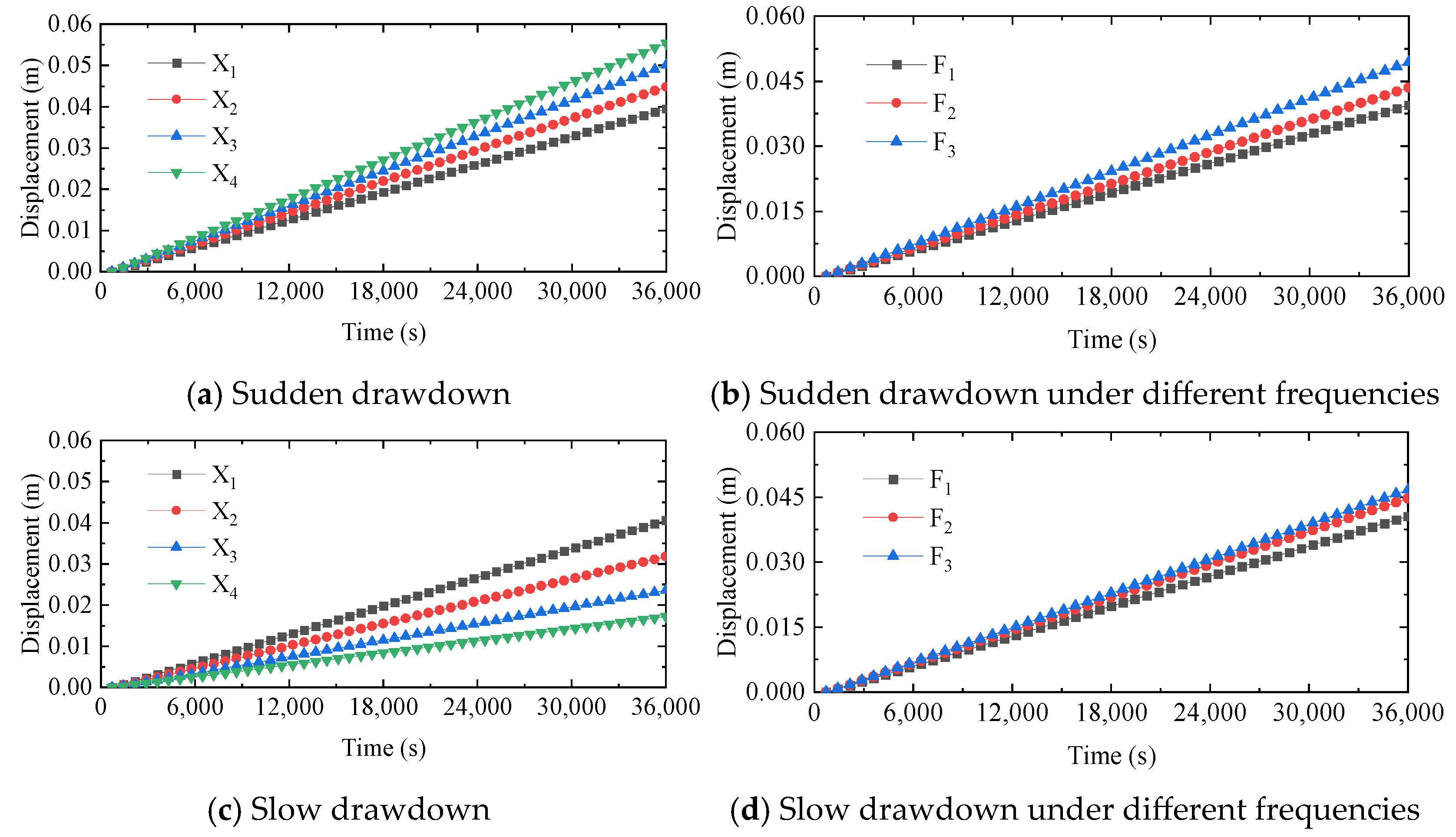
4.2. Finite Element Calculation of Seepage–Cyclic Load Coupling Disturbance
It has been verified in cases 1–12 that tunnel type A is more easily affected than tunnel type B, so studies on tunnel type A were conducted in cases 13–20. The displacement of tunnel A was calculated separately under sudden drawdown and slow drawdown of groundwater. F
i (
i = 1, 2, 3) represents different frequencies and magnitudes of cyclic load. X
i (
i = 1, 2, 3, 4) represents the roof displacement of different tunnels, with a larger
i indicating that the tunnels are closer to the road surface, 1 representing the farthest and 4 representing the nearest. It should be noted that the displacements in the figures refer to the roof displacement of the tunnel central section point. The results of cases 13–20 are shown in
Figure 11,
Figure 12,
Figure 13,
Figure 14,
Figure 15 and
Figure 16. The calculation results of the model are consistent with the observed trend. This indicates that the calculation of this model is reasonable.
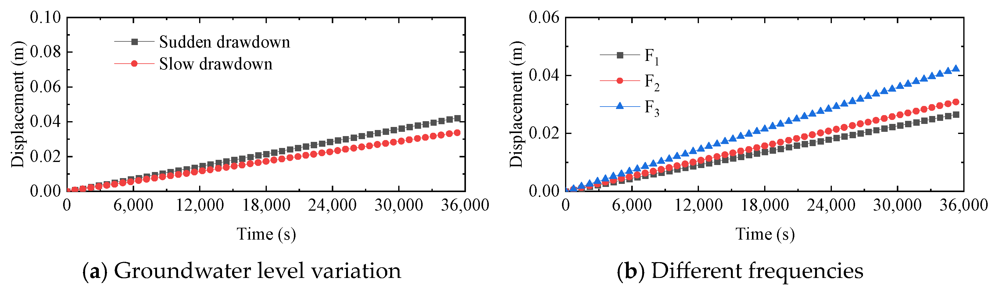
Figure 11 shows the roof displacement of a single tunnel under the action of F
3. It can be seen that the roof displacement is larger when the groundwater level drops sharply. As the frequency of the cyclic load increases, the displacement increases. The result for a parallel arrangement of tunnels is shown in
Figure 12. It can be seen that as the quantity of tunnels increases, the larger the roof displacement of the tunnels. Compared to the sudden drawdown of groundwater, the impact of traffic loads is relatively small under slow drawdown groundwater. As the frequency of action increases, the displacement increases.
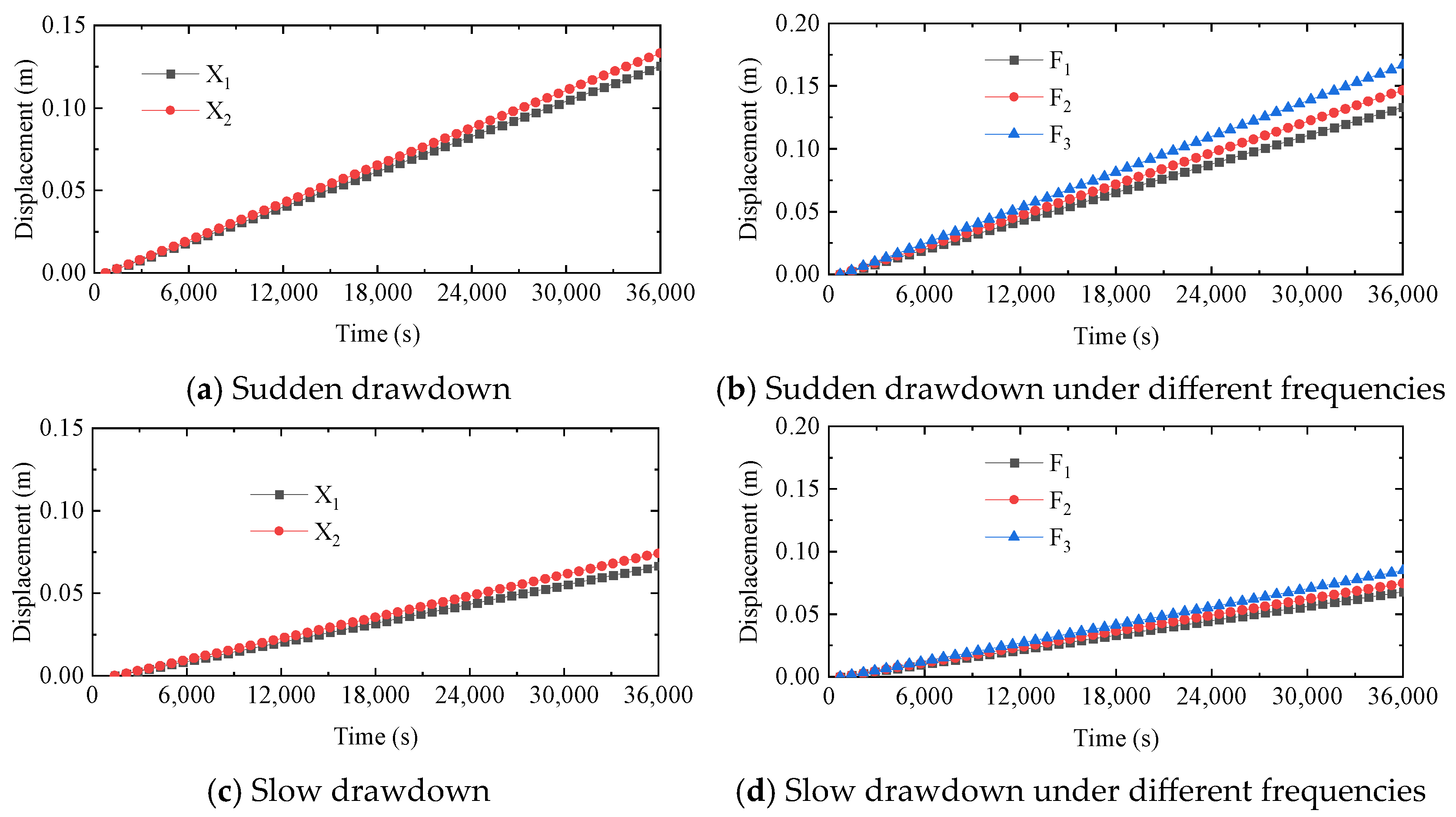
With respect to tunnel intersections, the roof displacements of the tunnel are shown in
Figure 13 and
Figure 14. It can be seen that the displacement of the tunnel is higher than that for the parallel arrangement of the tunnels under the same load. Similarly, for sudden drawdown of groundwater, the displacement is higher than that for slow drawdown.
Figure 15 and
Figure 16 show the coupling effect of seepage and traffic load when the river is located near the tunnel. It can be seen that, when the river is directly located above the tunnel roof, using the same frequency of loading, the roof displacement of the tunnel is higher than that in other cases. This indicates that the river has an adverse effect on the civil air defense tunnel. The difference between the frequencies of each action is relatively small, so the influence of rivers is the dominant factor.
Figure 17 and
Figure 18 show the coupling effect of seepage and traffic load when the material parameters change. In
Figure 17 and
Figure 18, it can be seen that as the material strength decreases, the larger the decrease in material strength and the larger the roof displacement of the tunnel at the same loading frequency. As the frequency of loading increases, the roof displacement of the tunnel gradually increases and is far worse than in the other cases. When the material strength decreases, the tunnel will be in a very unfavorable state under the coupling effect of seepage and load.
In order to express the displacement effect of factors clearly, based on the above results, the relationships between the influencing factors and displacements are summarized in
Table 6.
Changes in groundwater can induce displacement in civil air defense engineering structures. Sudden fluctuations in groundwater levels can significantly impact civil air defense structures through seepage effects. When coupled with traffic loads, underground tunnels may sustain damage, potentially leading to surface collapse. The reduction in tunnel strength can exacerbate roof displacement within the tunnel. Given that the strength of tunnel materials tends to decrease over time in old urban underground spaces, this issue warrants considerable attention.
The results of this study indicate the detrimental effects of vehicular dynamic loads on underground space structures. They illustrate that higher vehicle speeds correspond to increased vibration intensity, exacerbating the structural impact on underground spaces. Therefore, it is necessary to focus on the underground space in areas with fast vehicle speeds and areas where there are rivers. Regarding the problem of decreased strength of underground space structural materials, timely support and reinforcement operations are needed to avoid damage to underground space structures under seepage–traffic cyclic load coupling disturbance.
The above finding can provide a basis for evaluating the status of old underground spaces. Based on identified underground water and the local geological environment, it is possible to monitor the surroundings of old underground space structures. In addition, according to the potential impacts on older urban underground spaces, designers can make more scientific choices in the siting, design, and construction of new projects.
5. Conclusions
The effect of seepage–cyclic load coupling disturbance on the physical field was studied in this paper with respect to the collapse of old urban underground spaces. Based on extensive analysis, the primary conclusions are as follows:
(1) From the field visit and observation, the primary types of civil defense tunnels in the Beijing area can be categorized into two types. Based on geological conditions and burial depth, the effect of seepage–cyclic load coupling disturbance on the physical field in old urban underground spaces can be simulated using Plaxis 3D.
(2) Fluctuations in groundwater significantly affect underground space structures. The faster the groundwater level drops, the larger the ground displacement, which is detrimental to the structure. The more tunnels there are, the larger the ground displacement after the groundwater level changes. The more tunnels intersect, the larger the impact of seepage. The more the material strength decreases, the larger the impact of seepage and the greater the ground displacement. The larger the tunnel, the larger is the effect of seepage.
(3) The coupling effect of seepage and traffic load significantly influences tunnel roof displacement. Higher vehicle speeds and loading frequencies correlate with increased roof displacement, posing greater risks to structural stability. The variation in tunnel roof displacement is not only related to the variation in groundwater level, but also to the horizontal distance of the road: the closer to the road, the larger the displacement. The higher the decrease in the strength of underground structural materials, the higher the roof displacement of the tunnel, so it is easy for ground collapse to be caused under external loads. A 30% decrease in material strength can result in an approximately 1.5 times increase in displacement, with maximum displacement under different traffic loads varying by up to 3 times.
In engineering applications, special attention should be given to the condition of old urban underground spaces when the groundwater declines rapidly. Underground structures near traffic loads and rivers require particular monitoring to ensure safety. For newly constructed underground structures, it is advisable to avoid proximity to main roads and rivers above ground. These findings offer direct implications for engineering and construction practices in Beijing and other urban areas with similar geological and infrastructural conditions.


