Abstract
At present, without ground control points (GCPs), the positioning accuracy of remote sensing images often fails to meet the growing requirements for mapping accuracy. Multi-load synergy to improve accuracy without GCPs by eliminating the impact of stereo accuracy, which is caused by on-orbit measurement error, is urgently needed to improve large-scale mapping. In this study, we analyzed error sources in stereo imaging mode and found that vertical accuracy depends on the relative accuracy of attitude during symmetric stereoscopic mapping. With the assistance of small matrix charge-coupled device (CCD) images and the block adjustment method, relative accuracy of attitude was improved, allowing for the improvement in vertical accuracy without GCPs. The simulation results show that vertical accuracy in symmetric stereo mode is not affected by attitude system error. After the restoration of imaging attitude processed by a sequence of matrix CCD images, the relative accuracy of the attitude increased, and the accuracy of the elevation without GCPs improved significantly. The results demonstrate the feasibility of small matrix CCD-assisted stereo mapping.
1. Introduction
Optical satellites with stereo mapping observation capability are among the main means of data acquisition for global mapping. A number of high-resolution optical satellites with mapping capability have been launched worldwide. As in the case of the French SPOT-5 satellite, stereo observations can be achieved using a high-resolution stereo (HRS) camera with a planimetric accuracy of less than 50 m, and a vertical accuracy of less than 15 m, without the use of ground control points (GCPs) [1,2]. By using a three-linear-array of stereo cameras, the Japanese advanced land observation satellite (ALOS) satellite can implement global mapping with planimetric and vertical accuracies, reaching 8 and 10 m, respectively, without GCPs [3,4,5]. The Indian Cartosat stereo satellite can achieve 7.3 and 4.7 m planimetric and vertical accuracy, respectively, without GCPs, which satisfies the requirements of 1:50,000 mapping [6]. The satellites of the IKONOS and Worldview series, launched by the United States, can achieve stereo mapping with an accuracy of around 10 m, again without the use of GCPs. In recent years, the Worldview-3 satellite has achieved a planimetric accuracy of 2.16 m and a vertical accuracy of −1.61 m without GCPs, which satisfies the needs of 1:5000 mapping [7,8,9]. Optical satellites used for surveying and mapping in China belong to the ZiYuan-3 (ZY3) and TianHui-1 (TH1) series. The planimetric and vertical accuracies of ZY3-01 are 10 and 5 m, respectively, without GCPs [10,11,12,13], and those for TH1-01 are 10.3 and 5.7 m, respectively [14,15]. Thus, current mapping satellites can only meet the requirements of 1:50,000 stereo mapping.
Large-scale surveying and mapping places greater requirements on the hardware measurement accuracy and the stability of the platform. The accuracy by which attitude is measured by star sensors is of key importance. Some remote sensing satellites, which are equipped with advanced star sensors, can perform at a higher level. For example, Worldview-3 carries Ball Aerospace’s High Accuracy Star Tracker, which has a 0.2″ total error performance (1) [16,17]; hence, it can satisfy the accuracy need for 1:5000 or even larger-scale surveying and mapping. However, owing to technical restrictions, most satellites are equipped with relatively lower-accuracy star sensors. For example, the star sensor of Yaogan-24 in China is equipped with only 5″ error in the optical axis (3). Although the attitude accuracy can be improved a little by post-processing, it is not sufficient to meet the accuracy requirements for large-scale surveying and mapping [18,19].
The motivation of many researchers arises from the fact that overcoming the measurement limitations of the hardware is difficult in the short term. Instead, large-scale mapping technologies have been developed using multi-load synergy, a comprehensive approach to surveying and mapping in which various types of sensors are carried on a satellite platform to achieve high measurement accuracy. For example, in the TH1 satellite series, Wang et al. proposed matching line CCD images with matrix CCD images using the equivalent frame photo (EFP) bundle adjustment, which can solve the systematic distortion of the strip mode [20,21]. The vertical accuracy can reach the shuttle radar topography mission (SRTM) level without GCPs [15]. The ZY3-02 satellite carries a laser altimeter with a three-linear-array camera. After calibration through multiple areas, it has a laser spot vertical accuracy of 2–3 m in areas where the terrain slope is less than 2°. The absolute accuracy of height measurements for flat areas is better than 1 m [22,23]. However, how to combine laser data with image data to improve the accuracy of three-linear-array stereo mapping requires further study.
Given that accuracy requirements for mapping are increasing, and current measurements do not always live up to those expectations, in this study we developed a method to restore satellite imaging attitude and to improve vertical accuracy without GCPs by using a combination of small matrix CCD cameras with linear array CCD cameras. First, our formula derivation proves that, under the symmetrical stereo mode, the vertical accuracy of satellite mapping is determined by the relative precision of the attitude. High-precision image attitude can be restored by using sequences of small matrix CCD images, after which vertical accuracy can be improved without the use of GCPs. We collected sequences of matrix CCD images and two-linear-array stereo images by simulation for joint processing. The results show that, when using small matrix CCD images to recover imaging attitude, the accuracy of elevation without GCPs is significantly improved, which confirms the feasibility of this method.
2. Method
2.1. Accuracy Analysis of Symmetrical Stereo Mode
The error sources that affect the accuracy of surveying and mapping satellites include exterior orientation elements (e.g., position or attitude) and inner orientation elements. The influence of orbit error can be ignored, because orbit post-determination is accurate to the centimeter level [24]. Inner orientation elements can be eliminated by high-precision on-orbit calibration. As a result, attitude errors (e.g., pitch, roll, and yaw) are the main error sources affecting stereo mapping without GCPs [25]. Global surveying and mapping rely on the use of stereo cameras to photograph the same area from different pitch perspectives. Figure 1 shows a schematic diagram of stereo observations for both satellite forward-view and backward-view cameras. Research has shown that roll and yaw error will lead to forward intersections not being at the same point; however, this can be effectively eliminated using the free net adjustment [21,26]. Therefore, the vertical accuracy of stereo mapping without GCPs depends on the accuracy of pitch, and hence our discussion will be in the XOZ plane (Figure 1).
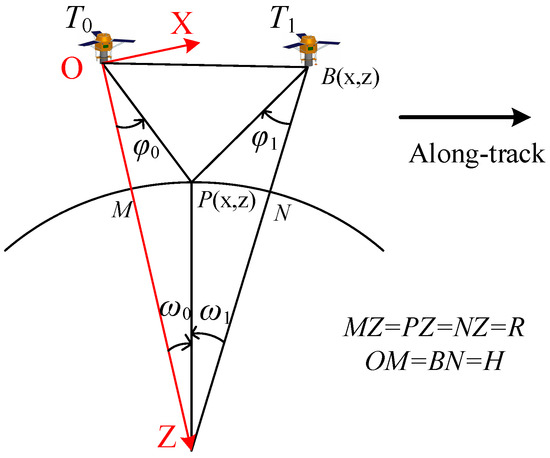
Figure 1.
Schematic of camera stereo intersection.
As shown in Figure 1, the forward-view and backward-view cameras take images of the same area at times T0 and T1, respectively. Assuming that the orbit coordinate system at time T0 is a benchmark, the Z-axis of the orbit coordinate system is defined as pointing to the center of the Earth, while X-axis is defined as pointing to the satellite flight direction (along-track). Under the XOZ coordinate system, satellite images at point P have a pitch angle of and coordinates (Px, Pz). Satellite coordinates are (Bx, Bz) at time T1. Defining counterclockwise rotation as positive, according to the relationship shown in Figure 1, we can obtain the coordinates of point P from the equation:
Assuming that the altitude of the satellite orbit is H, and the average radius of Earth is R, it is obvious that:
By differentiating Pz in Equation (1), we obtain:
For the vertical accuracy of the forward intersection, the best condition is dPz = 0, such that:
The base:height ratio will be controlled around 1 in the normal stereo mode, where . As and , we obtain based on Equation (2). Therefore, the angle of the Z-axis between times T0 and T1 is about 4.6°. Since this is so small, we can regard the Z-axis as being in the same direction at times T0 and T1, with Bz = 0. When combined with Equation (3), we get:
If there exist systematic errors, then . Fulfilling Equation (5) in the stereo mode of the same orbit requires or , based on a data range of . As the perspective of the forward view and backward view cannot be the same, the situation of cannot exist; therefore, is the symmetric stereo mode. When , Equation (3) can be calculated as:
When the attitude errors of the two stereo times are the same size and direction, the elevation errors of the forward intersection are 0 (Figure 2).
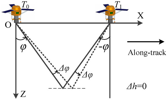
Figure 2.
Elevation errors at the stereo intersection. The solid line shows the true intersection; the dashed line shows the intersection with error.
Where the stereo mode has different sides but the same track, and . Then, and have opposite signs, while and have the same sign. In this case, errors will be canceled out, and vertical accuracy is high. Where the stereo mode has the same side and track, if (Figure 3) and , then and have opposite signs, while and have the same sign. Again, errors will cancel out and the vertical accuracy will be high. In summary, for stereo modes with the same track, the influence of attitude errors will be canceled out in the forward intersection, the resulting symmetric stereo imaging will have a high elevation accuracy, and the vertical error of the forward intersection will only be affected by random noise in the attitude.
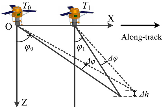
Figure 3.
Same-side elevation intersection error.
Similarly, the planimetric accuracy of forward intersection is derived as follows:
Under the conditions of stereo symmetry, if , , we have:
And the planimetric accuracy is high only when . This requires that attitude errors be in the opposite direction for stereo imaging, which is generally difficult to achieve. Therefore, under stereo conditions without GCPs, the possibility that planimetric accuracy is influenced by systematic attitude errors cannot be eliminated.
Based on the method above, the vertical accuracy of the forward intersection depends on the relative accuracy of attitude. The main elements that reduce the relative accuracy of attitude are (1) random error, such as the noise resulting from attitude measurement equipment (e.g., star sensor noise and gyro noise); (2) attitude high-frequency error, such as high-frequency jitter of the platform (e.g., that caused by momentum wheel activities) [27]; (3) attitude low-frequency drift, such as angle change between the CCD camera and star sensor caused by drift of the star sensor’s optic axis or by on-orbit thermal environment change. The third factor has the greatest influence when GCPs are not used [28,29,30,31].
As shown in Figure 4, the period of on-orbit low-frequency drift error is difficult to eliminate by means of a small number of calibration fields. During the period of stereo imaging (≤100 s), attitude error was mainly systematic and was about −1.7″; however, there were also minor changes of about 0.1″. Based on the above derivation, the systematic part of attitude low-frequency drift can be offset by symmetric stereo mode during the stereo time, but changeable parts of the attitude errors affect stereo vertical accuracy. Through processing a sequence of small matrix CCD images, the vertical accuracy of forward intersection caused by random errors of attitude measurement and low-frequency drift could be reduced, thereby improving the accuracy of elevation without GCPs.
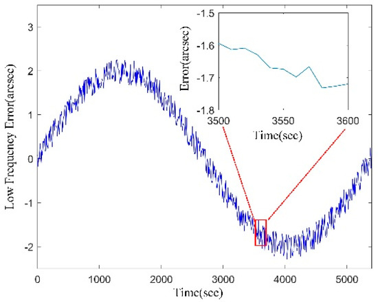
Figure 4.
Attitude low-frequency drift errors of the on-orbit satellite.
2.2. Vertical Accuracy Improvement Using Small Matrix CCD
Figure 5 shows synchronous observations of a small matrix CCD camera and a linear array CCD camera. The satellite design ensures that the adjacent images of a small matrix CCD have an overlap. Generally, the small matrix CCD in orbit needs to be calibrated first because of the potential for lens distortion or optical perturbations. The method currently used for calibration of matrix CCDs has been extensively developed using images covering calibration fields, and the interior orientation is better than 0.3 pixels [1,2,3,4,5,32]. Therefore, we assume that the matrix CCDs are perfectly planar after calibration. Under on-orbit conditions, attitude error is not considered, as shown in Figure 6. The homonymous points (p and q) of the two adjacent images should intersect at the same ground position (S); however, because of different attitude errors for moments and , the two points cannot intersect in the same position [33]. Therefore, the attitude of moment relative to moment can be restored by positioning the consistency constraints of homonymous points at moments and .
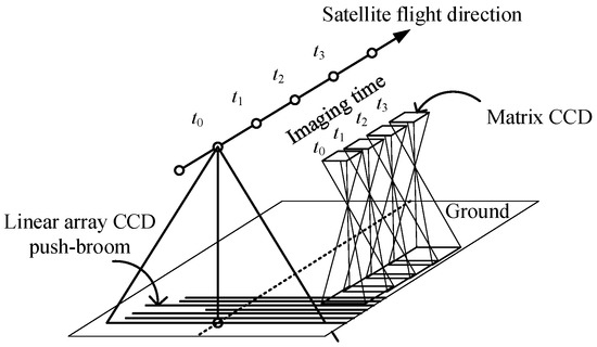
Figure 5.
Imaging schematic of a small matrix charge-coupled device (CCD) and linear array CCD.
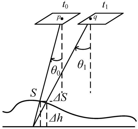
Figure 6.
Schematic of the intersection of homonymous points.
For matrix CCD images at moments and , we extracted the homonymous points and ; represents the position vector of ground object S corresponding to and ; represents the satellite’s position in the Cartesian coordinates of WGS84 at time ; and represents the scaling factor at time . Assuming that represents the principal point and focal length of the matrix CCD, the consistency constraints of positioning mode [32,34,35,36] can be built as:
where represents the rotation matrix from camera coordinate to WGS84 coordinate at time (t stands for or in Equation (9)); and represents the attitude compensation of the small matrix CCD image at moment , which constitutes and by:
where , , and so on. For any pair of homonymous points and , the unknown parameters in Equation (9) are the attitude compensation of two time points (, ) and the ground position of the homonymous points.
For any time in Equation (9), for example, , let:
From which we get:
After linearizing the above equation, the error equation can be calculated as [10,26,36,37]:
where are the Jacobi matrices of each unknown parameter, and are the correction numbers of the ground positions of the homonymous points. By transforming the equation to the matrix form:
where
For any pair of homonymous point and , we can create four equations similar to Equation (13). All homonymous points constitute the error equation as follows:
Taking all the small matrix CCD imaging times and homonymous points into the equation, we can first eliminate the unknown , then acquire the attitude correction parameter of each image by:
Hence, we have the coordinate correction parameters according to the obtained . Then, using Equations (13)–(16) with iteration until the new is small enough, we obtain the final attitude compensation matrix for each matrix CCD imaging time by Equation (10).
In Figure 7, A1 represents the real attitude in the process of satellite imaging, while A0 represents the on-orbit measurement attitude (this may contain attitude random error, attitude low-frequency drift error, and attitude high-frequency error). According to our method, through the positioning consistency constraints of homonymous points, we can restore the attitude of moment relative to moment . The actual recovered attitude is shown as A2 in Figure 7. This process can restore the relative relations of attitude at different moments [33]. When using A0 as the attitude for processing, the attitude error is random. When using A2, the attitude error is systematic (). As derived from Equation (5), when the satellite uses the symmetric stereo mode, the attitude systematic error does not affect vertical accuracy without GCPs. Therefore, restoring relative attitude through sequences of small matrix CCD images actually improves vertical accuracy by raising the relative accuracy of attitude data.
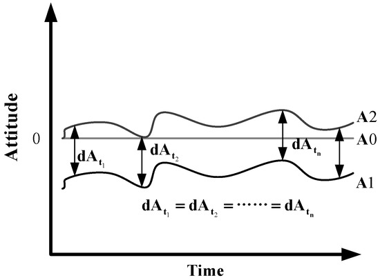
Figure 7.
Schematic of relative attitude.
Finally, by applying the attitude compensation matrix to the original attitude measurement parameters, we obtain the corrected attitude, which can be used in the production of the forward intersection between the forward- and backward-view linear array camera.
3. Results and Discussion
3.1. Experimental Data Simulation
The experimental parameters were simulated based on existing satellite design. Orbit, attitude, and linear array CCD parameters were from the ZY3 platform [38]. The digital orthophoto map (DOM) and digital elevation model (DEM) data of the Songshan (Henan province, China) calibration field were used as the base image. Specific parameters settings are shown in Table 1 and Table 2.

Table 1.
Orbit and attitude parameters.
Table 2.
Camera parameters.
Figure 8 shows the simulation results for the forward and backward view of the linear array CCD images and small matrix CCD images.
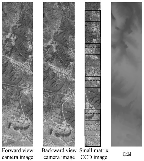
Figure 8.
Simulation image schematic of the linear array charge-coupled device (CCD) and the small matrix CCD.
3.2. Symmetry and Vertical Accuracy
First, we verified the relationship between symmetry and vertical accuracy. During the initial simulation conditions, the attitude systematic error was set to omega =5″, while the attitude stability and random error were set to 0. Under different symmetry conditions, the vertical accuracies of stereo image production according to the forward- and backward-view cameras are shown in Table 3 and Figure 9. At symmetry condition value 1, at which the pitch angles of the forward and backward cameras were symmetrical, the vertical accuracy reached 0.043 m. With increasing or decreasing symmetry, the vertical accuracy was reduced. By contrast, the planimetric accuracy was hardly affected by the stereo forward/backward angle.
Table 3.
Simulation results for symmetry and vertical accuracy.
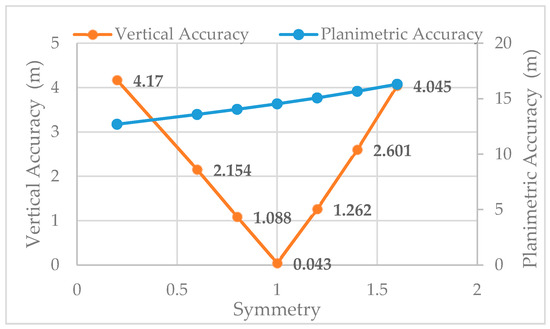
Figure 9.
Symmetry and vertical accuracy.
Assuming the base:height ratio was consistent, with forward/backward cameras at −22°/+22° and a base:height ratio of 0.8, we simulated the forward camera with a 5° interval and calculated the corresponding angle of the backward camera. The attitude systematic error was omega =5″, while attitude stability and random error were 0. The vertical accuracies under different symmetries were determined according to the production of stereo images by the forward/backward camera (Table 4 and Figure 10). Again, we found that the vertical accuracy of stereo images was highest under symmetrical mode. With the reduction of symmetry, the vertical accuracy decreased, and the symmetric stereo was unable to improve the planimetric accuracy.
Table 4.
Vertical accuracy simulation of stereo images under the same base:height ratio.
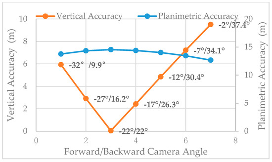
Figure 10.
Vertical accuracy under the same base:height ratio.
The simulation results show that, in line with the foregoing theoretical derivation, the symmetric mode is the optimal stereo observation mode when attitude systematic errors exist. In actual forward/backward camera stereo images, even in symmetry stereo mode, the attitude errors at different times are different (i.e., the attitude error is not systematic). This will lead to a decrease in vertical accuracy, which requires matrix CCD image processing.
3.3. Promotion of Matrix CCD Images for Vertical Accuracy
As shown in Figure 8, adjacent images from the small matrix CCD were matched to acquire the homonymous points. When all of these points were put into the regional network adjustment mode, we were able to obtain the attitude compensation matrix for every image. Then, we compared the vertical accuracies of two stereo products: (1) products produced by forward intersection of forward/backward images through the original simulation attitude; and (2) products produced by forward intersection of forward/backward images through a modified attitude, which are compensated for by matrix .
Our experiment was performed to evaluate the vertical accuracy of the forward intersection products under the following simulation conditions: attitude stability (the three axis errors were 0.0001°/s or 0.0005°/s), attitude system error (the three axis errors were 5″ or 10″), and attitude random error (the three axis errors were 1″or 2″). Vertical accuracy results are given after small matrix CCD image modification (Figure 11).
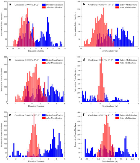
Figure 11.
Vertical accuracy distribution before and after matrix charge-coupled device (CCD) processing (the sub-figures (a–f) have different simulation condition parameters which contains: attitude stability, e.g., 0.0005°/s; attitude systematic error, e.g., 5″; and attitude random error, e.g., 2″).
By calculating the root-mean-square error (RMSE) of the intersection point accuracy, we aquire the following Table 5:
Table 5.
Vertical accuracy statistics.
- For the original RMSE accuracy of (Figure 11a,b), the attitude stability was 0.0005°/s and attitude random error was 2″. When the systematic error increased from 5″ to 10″, the vertical accuracy only changed from 5.566 to 4.757 m, but the planimetric error increased from 17.978 to 37.393 m. When the systematic error doubled, the vertical accuracy was almost the same (Figure 11d,e). This confirms that under the symmetric stereo mode, attitude systematic error has little influence on vertical accuracy. However, the symmetric stereo mode cannot offset attitude systematic error for planimetric accuracy. After matrix CCD processing, the vertical accuracy increased from 5.566 to 1.662 m (Figure 11a), and from 2.826 to 0.395 m (Figure 11d), while the planimetric accuracy did not change significantly. These results confirm that, under the symmetric stereo condition, images from the small matrix CCD can effectively restore the relative accuracy of attitude, but are unable to improve the absolute accuracy of attitude. In summary, vertical accuracy can be increased greatly by using matrix CCD processing, but planimetric accuracy changes little.
- Compared with the original accuracy (Figure 1a,c), under attitude stability of 0.0005°/s and systematic error of 5″, and as attitude random error changed from 2″ to 1″, vertical accuracy rose from 5.566 to 3.952 m. After small matrix CCD image processing, vertical accuracy increased to 1.662 m. The same situation can be seen in Figure 11d,f, which verifies that under symmetric stereo conditions, vertical accuracy is affected by the random error of the measurement (including the attitude low-frequency drift that removed the systematic part). After matrix CCD processing, the relative accuracy of the attitude was increased, and the vertical accuracy was also improved.
- By comparing Figure 11a–c with Figure 11d–f, the relative accuracy of the attitude can be seen to have increased indirectly with increasing attitude stability, such that the vertical accuracy without GCPs improved under symmetric stereo conditions. When attitude stability is high, restraining the influence of random errors and low-frequency drift of attitude through matrix CCD can result in vertical accuracy of better than 0.4 m without GCPs, which is suitable for large-scale mapping.
4. Conclusions
Based on the stereo vertical accuracy deduction of a linear push-broom satellite, we have developed a method for surveying and mapping assisted by a small matrix CCD camera. The results show that this method greatly improves vertical accuracy without the use of GCPs. Simulation parameters (i.e., orbit and attitude) were set according to those of the ZY3 satellite. At the same time, forward/backward linear array images and matrix CCD images were simulated. The symmetric stereo and matrix CCD processing effects were then verified. The experimental results show the following.
- Under the symmetric stereo mode, attitude systematic errors can be canceled out, which guarantees a high vertical accuracy.
- Attitude stability and attitude random errors are the main error sources for vertical accuracy under the symmetric stereo mode. When these are decreased, the vertical accuracy increases.
- The relative accuracy of the attitude can be improved using matrix CCD image processing. By using the improved attitude in stereo image production, the vertical accuracy without GCPs can be significantly improved.
We are responsible for the aspects of the design of the upcoming Gaofen-7 and Large-scale Surveying and Mapping Satellite of China. Results have verified that under the existing conditions of star sensors, the attitude measurement accuracy is insufficient. The Gaofen-7 and Large-scale Surveying and Mapping Satellite can only satisfy the 1:10,000 and 1:5000 scales of planimetric accuracy, respectively. However, they are unsatisfactory with respect to the corresponding vertical accuracy. Our method provides a new solution for these two satellites to achieve the accuracy requirement without GCPs. At present, the method to combine linear array CCD with small matrix CCD is at the design stage. In the future, we expect our proposed method to be of use in large-scale surveying and mapping on the Gaofen-7 and the Large-scale Surveying and Mapping Satellite.
Acknowledgments
This work was supported by the key research and development program of the Ministry of Science and Technology (Grant No. 2016YFB0500801), Special Fund for High Resolution Images Surveying and Mapping Application System (Grant No.AH1601-10), the National Natural Science Foundation of China (Grant No. 41601490, Grant No. 91538106, Grant No. 41501503, Grant No. 41501383), and the Open Research Fund of the State Key Laboratory of Information Engineering in Surveying, Mapping, and Remote Sensing (Grant No. 15E02). The authors also thank the anonymous reviewers for their constructive comments and suggestions.
Author Contributions
Zhichao Guan and Yonghua Jiang conceived and designed the experiments; Zhichao Guan performed the experiments; Zhichao Guan, Yonghua Jiang, and Guo Zhang analyzed the data; Yonghua Jiang contributed analysis tools; Zhichao Guan and Yonghua Jiang wrote the paper.
Conflicts of Interest
The authors declare no conflict of interest.
References
- Bouillon, A. SPOT5 HRG and HRS first in-flight geometric quality results. In Proceedings of the International Symposium on Remote Sensing, Crete, Greece, 22–27 September 2002; Volume 4881, pp. 212–223. [Google Scholar]
- Breton, E.; Bouillon, A.; Gachet, R.; Delussy, F. Pre-flight and in-flight geometric calibration of SPOT 5 HRG and HRS images. Int. Arch. Photogram. Remote Sens. Spat. Inf. Sci. 2002, 34, 20–25. [Google Scholar]
- Tadono, T.; Shimada, M.; Watanabe, M.; Hashimoto, T.; Iwata, T. Calibration and validation of PRISM onboard ALOS. Int. Arch. Photogram. Remote Sens. Spat. Inf. Sci. 2004, 35, 13–18. [Google Scholar]
- Tadono, T.; Shimada, M.; Murakami, H.; Takaku, J. Calibration of PRISM and AVNIR-2 onboard ALOS “daichi”. IEEE Trans. Geosci. Remote Sens. 2009, 47, 4042–4050. [Google Scholar] [CrossRef]
- Takaku, J.; Tadono, T. PRISM on-orbit geometric calibration and DSM performance. IEEE Trans. Geosci. Remote Sens. 2009, 47, 4060–4073. [Google Scholar] [CrossRef]
- Muralikrishnan, S.; Pillai, A.; Narender, B.; Reddy, S.; Venkataraman, V.R.; Dadhwal, V.K. Validation of Indian national DEM from Cartosat-1 data. J. Indian Soc. Remote Sens. 2013, 41, 1–13. [Google Scholar] [CrossRef]
- Longbotham, N.W.; Pacifici, F.; Malitz, S.; Baugh, W.; Campsvalls, G. Measuring the Spatial and Spectral Performance of WorldView-3. In Proceedings of the Fourier Transform Spectroscopy and Hyperspectral Imaging and Sounding of the Environment, Lake Arrowhead, CA, USA, 1–4 March 2015. [Google Scholar]
- Li, G.Y.; Hu, F.; Zhang, C.Y. Introduction to Imaging Mode of WorldView-3 Satellite and Image Quality Preliminary Evaluation. Bull. Surv. Map. 2015, 2, 11–16. [Google Scholar]
- Hu, F.; Gao, X.M.; Li, G.Y.; Li, M. DEM extraction from Worldview-3 stereo-images and accuracy evaluation. Int. Arch. Photogram. Remote Sens. 2016, XLI-B1, 327–332. [Google Scholar] [CrossRef]
- Wang, T.Y.; Zhang, G.; Li, D.R.; Tang, X.M.; Jiang, Y.H.; Pan, H.B. Geometric accuracy validation for ZY-3 satellite imagery. IEEE Geosci. Remote Sens. Lett. 2014, 11, 1168–1171. [Google Scholar] [CrossRef]
- Tang, X.M.; Zhang, G.; Zhu, X.Y.; Pan, H.B.; Jiang, Y.H.; Zhou, P. Triple linear-array image geometry model of ziyuan-3 surveying satellite and its validation. Acta Geod. Cartogr. Sin. 2012, 4, 33–51. [Google Scholar] [CrossRef]
- Jiang, Y.H.; Zhang, G.; Tang, X.M.; Zhu, X.Y.; Qin, Q.; Li, D.R. High accuracy geometric calibration of ZY-3 three-line image. Acta Geod. Cartogr. Sin. 2013, 42, 523–529. [Google Scholar]
- Pan, H.B.; Zhang, G.; Tang, X.M.; Wang, X.; Zhou, P.; Xu, M. Accuracy analysis and verification of ZY-3 products. Acta Geod. Cartogr. Sin. 2013, 42, 738–751. [Google Scholar]
- Wang, R.X.; Wang, J.R.; Hu, X. First Practice of LMCCD Camera Imagery Photogrammetry. Acta Geod. Cartogr. Sin. 2014, 43, 221–225. [Google Scholar]
- Wang, R.X.; Hu, X.; Wang, J.R. Photogrammetry of Mapping Satellite-1 without Ground Control Points. Acta Geod. Cartogr. Sin. 2013, 42, 1–5. [Google Scholar]
- Michaels, D. Ball aerospace star tracker achieves high tracking accuracy for a moving star field. In Proceedings of the 2005 IEEE Aerospace Conference, Big Sky, MT, USA, 5–12 March 2005; pp. 1–7. [Google Scholar]
- “WorldView-3”. Earth Observation Portal. Available online: https://directory.eoportal.org/web/eoportal/satellite-missions/v-w-x-y-z/worldview-3 (accessed on 30 October 2017).
- Wang, M.; Fan, C.; Yang, B.; Jin, S.; Pan, J. On-Ground Processing of Yaogan-24 Remote Sensing Satellite Attitude Data and Verification Using Geometric Field Calibration. Sensors 2016, 16, 1203. [Google Scholar] [CrossRef] [PubMed]
- Tang, X.; Xie, J.; Wang, X.; Jiang, W. High-Precision Attitude Post-Processing and Initial Verification for the ZY-3 Satellite. Remote Sens. 2015, 7, 111–134. [Google Scholar] [CrossRef]
- Wang, R.X.; Hu, X.; Yang, J.F. Proposal to Use LMCCD Camera for Satellite Photogrammetry. Acta Geod. Cartogr. Sin. 2004, 33, 116–120. [Google Scholar]
- Wang, R.X.; Wang, J.R.; Yang, J.F. The Satellite Photogrammetric performance of LMCCD camera. Sci. Surv. Map. 2004, 29, 10–12. [Google Scholar]
- Tang, X.M.; Xie, J.F.; Fu, X.K.; Fan, M.O.; Li, S.N.; Dou, X. Zy3-02 laser altimeter on-orbit geometrical calibration and test. Acta Geod. Cartogr. Sin. 2017, 46, 714–723. [Google Scholar]
- Tang, X.M.; Li, G.Y.; Gao, X.M.; Chen, J. The rigorous geometric model of satellite laser altimeter and preliminarily accuracy validation. Acta Geod. Cartogr. Sin. 2016, 45, 1182–1191. [Google Scholar]
- Guo, J.; Zhao, Q.L.; Li, M.; Hu, Z.G. Centimeter level orbit determination for HY2A using GPS data. Geomat. Inf. Sci. Wuhan Univ. 2013, 38, 52–55. [Google Scholar]
- Jiang, Y.H.; Xu, K.; Zhang, G. A Method of Exterior Auto-Calibration for Linear CCD Array Pushbroom Optical Satellites. J. Tongji Univ. 2016, 44, 1266–1271. [Google Scholar]
- Wang, Z.Z. The Principle of Photogrammetry; China Surveying and Mapping: Beijing, China, 1979. [Google Scholar]
- Iwata, T. High-Bandwidth Attitude Determination Using Jitter Measurements and Optimal Filtering. In Proceedings of the AIAA Guidance, Navigation, and Control Conference, Chicago, IL, USA, 10–13 October 2009. [Google Scholar]
- Lu, X.; Wu, Y.P.; Zhong, H.J.; Li, C.Y.; Zheng, R. Low Frequency Error Analysis of Star Sensor. Aerosp. Control Appl. 2014, 40, 1–7. [Google Scholar]
- Xiong, K.; Zong, H.; Tang, L. On Star Sensor Low Frequency Error In-Orbit Calibration Method. Aerosp. Control Appl. 2014, 40, 8–13. [Google Scholar]
- Lai, Y.; Gu, D.; Liu, J.; Li, W.; Yi, D. Low-Frequency Error Extraction and Compensation for Attitude Measurements from STECE Star Tracker. Sensors 2016, 16, 1669. [Google Scholar] [CrossRef] [PubMed]
- Wang, R.X.; Wang, J.R.; Hu, X. Low-frequency Errors Compensation of Attitude Determination System in Satellite Photogrammetry. Acta Geod. Cartogr. Sin. 2016, 45, 127–130. [Google Scholar] [CrossRef]
- Jiang, Y.H.; Zhang, G.; Tang, X.M.; Li, D.R.; Huang, W.C.; Pan, H.B. Geometric Calibration and Accuracy Assessment of ZiYuan-3 Multispectral Images. IEEE Trans. Geosci. Remote Sens. 2014, 52, 4161–4172. [Google Scholar] [CrossRef]
- Jiang, Y.H.; Zhang, G.; Tang, X.M.; Li, D.R.; Huang, W.C. Detection and Correction of Relative Attitude Errors for ZY1-02C. IEEE Trans. Geosci. Remote Sens. 2014, 52, 7674–7683. [Google Scholar] [CrossRef]
- Pan, H.B.; Zhang, G.; Tang, X.M.; Zhou, P.; Jiang, Y.H.; Zhu, X.Y. The Geometrical Model of Sensor Corrected Products for ZY-3 Satellite. Acta Geod. Cartogr. Sin. 2013, 42, 516–522. [Google Scholar]
- Riazanofi, S. SPOT Satellite Geometry Handbook; SPOT Image: Toulouse, France, 2002. [Google Scholar]
- Jiang, Y.H.; Zhang, G.; Chen, P.; Li, D.R.; Tang, X.M.; Huang, W.C. Systematic error compensation based on a rational function model for ziyuan1-02c. IEEE Trans. Geosci. Remote Sens. 2015, 53, 3985–3995. [Google Scholar] [CrossRef]
- Jiang, Y.H.; Zhang, G.; Tang, X.; Li, D.R.; Wang, T.; Huang, W.C. Improvement and assessment of the geometric accuracy of chinese high-resolution optical satellites. IEEE J. Sel. Top. Appl. Earth Obs. Remote Sens. 2017, 8, 4841–4852. [Google Scholar] [CrossRef]
- Li, D.R. China’s First Civilian Three-line-array Stereo Mapping Satellite: ZY-3. Acta Geod. Cartogr. Sin. 2012, 41, 317–322. [Google Scholar]
© 2017 by the authors. Licensee MDPI, Basel, Switzerland. This article is an open access article distributed under the terms and conditions of the Creative Commons Attribution (CC BY) license (http://creativecommons.org/licenses/by/4.0/).