Global Registration of Terrestrial Laser Scanner Point Clouds Using Plane-to-Plane Correspondences


1
Department of Geomatics, Federal University of Paraná, Curitiba, Paraná 19001, Brazil
2
Department of Infrastructure Engineering, University of Melbourne, Parkville, VIC 3010, Australia
*
Author to whom correspondence should be addressed.
Remote Sens. 2020, 12(7), 1127; https://doi.org/10.3390/rs12071127
Submission received: 3 March 2020
/
Revised: 17 March 2020
/
Accepted: 26 March 2020
/
Published: 2 April 2020
(This article belongs to the Special Issue Laser Scanning and Point Cloud Processing)
Abstract
:Registration of point clouds is a central problem in many mapping and monitoring applications, such as outdoor and indoor mapping, high-speed railway track inspection, heritage documentation, building information modeling, and others. However, ensuring the global consistency of the registration is still a challenging task when there are multiple point clouds because the different scans should be transformed into a common coordinate frame. The aim of this paper is the registration of multiple terrestrial laser scanner point clouds. We present a plane-based matching algorithm to find plane-to-plane correspondences using a new parametrization based on complex numbers. The multiplication of complex numbers is based on analysis of the quadrants to avoid the ambiguity in the calculation of the rotation angle formed between normal vectors of adjacent planes. As a matching step may contain several matrix operations, our strategy is applied to reduce the number of mathematical operations. We also design a novel method for global refinement of terrestrial laser scanner data based on plane-to-plane correspondences. The rotation parameters are globally refined using operations of quaternion multiplication, while the translation parameters are refined using the parameters of planes. The global refinement is done non-iteratively. The experimental results show that the proposed plane-based matching algorithm efficiently finds plane correspondences in partial overlapping scans providing approximate values for the global registration, and indicate that an accuracy better than 8 cm can be achieved by using our global fine plane-to-plane registration method.
1. Introduction
In recent years, the rising role of building information modeling (BIM) has driven the market for static terrestrial laser scanners (TLS). TLS is an efficient and cost-effective technology for rapid and accurate collection of 3D point clouds. TLS point clouds are the most suitable data source for the generation of as-built BIMs, which are a crucial tool for many construction and architecture professionals. To derive globally consistent 3D point cloud models from TLS with high positional accuracy, registration is a mandatory task. Typically, in the existing frameworks, the registration of multiple point clouds is divided into a pairwise registration step and a global fine registration step. Pairwise registration involves finding feature correspondences between pairs of point clouds and minimizing the sum of residuals over all such feature correspondences for the estimation of transformation parameters (3D rotation matrix and 3D translation vector), which establish the relative orientation for each pair of scans in a common coordinate system. In practice, pairwise registration using free-form correspondences (e.g., iterative closest point algorithm [1]), feature point-based (e.g., keypoints) methods [2,3,4,5,6,7], or primitive-based (e.g., lines or planar surfaces) approaches [8,9,10,11,12,13] should be applied first to obtain the transformation parameters. However, a problem which arises in the registration of multiple point clouds is that corresponding scan features may still present significant residual errors from pairwise registration task. As a direct consequence, most of the pairs of registered point clouds will contain loop closing errors, thus reducing their local metric accuracy. Then, the global refinement should be used to minimize the influence of pairwise alignment errors on the transformation parameters, by distributing the residual errors evenly across the scan project [14]. Our present contribution is twofold. First, a plane matching strategy by decoupling rotation and translation parameters is proposed. The proposed matching algorithm makes use of a new parametrization based on complex numbers to find the correspondence between pairs of segmented planes. Second, a new global closed-form solution is proposed via graph-based formulation adapted for plane-to-plane correspondences. The proposed solution refines the sensor positions by treating the 3D points and their corresponding surface normal as observations. To the best of our knowledge, the proposed method is the first using this approach.
The rest of the paper is organized as follows. Section 2 provides the related works in point cloud registration, helping the reader to gain an insight into the registration problem. The studied area, our proposed plane-based matching approach, and our global fine registration solution based on plane correspondences are presented in Section 3. Experimental evaluation of the proposed solution on real datasets and a discussion about the potential and limitation of the proposed method are given in Section 4. Finally, the paper is concluded in Section 5.
2. Related Work
Typically, standard global refinement solutions first find the transformation parameters using [1], then evenly redistribute loop closing errors with the help of a graph-based optimization such as the one proposed by [15], which has been extended to 3D by [16]. This task is formulated as a scan graph, in which each scan denotes a node, and each edge highlights the spatial constraint between the pairs of nodes. A globally consistent registration of multiple point clouds via graph optimization was proposed by [14]. The authors find the coarse alignments using an unambiguous geometric keypoint configuration able to reduce the number of candidates that are sampled in the iteration process, called on K-4PCS [6], and the pairwise candidate solutions are filtered using a discrete graphical model of the scan network. Then, least-squares optimization [15] is used to evenly distribute the residual error. Ji et al. [13] generated a globally consistent 3D map of high-speed viaduct point clouds using closing condition and external geometric constraints. Their proposed method uses artificial targets for the iterative pairwise registration step. The pairwise transformations are also refined with [1], followed by global refinement to evenly spread the residual errors, as described in [15]. Yang et al. [17] use a branch-and-bound strategy to globally solve the objective function. It first uses the iterative closest point algorithm for a coarse registration task and refines the transformation parameters with the algorithm of [15]. The approach proposed by Huber and Hebert [2] uses surfaces and a Bayesian filter for alignment of multi-view 3D point clouds. The main disadvantage of this method is its high computational cost. Other global refinement approaches rely on general graph optimization [18], bundle adjustment [19], low-rank sparse decomposition strategy [20], kernel-based energy function [21] and visual bag of words [22], which are computationally less attractive.
The aforementioned existing methods for registration of multiple point clouds are prominently iterative free-form or point-based correspondences. Despite their popularity, iterative solutions have several limitations. For instance, they are not effective for sparse point clouds, require good approximate values to avoid convergence to weak local minima, they are sensitive to noise, and involve a matching step which incurs a high computational cost. Furthermore, when a downsampling step is applied, as in [6], the details of objects in the scene may be lost [12]. In contrast, closed-form solutions estimate the transformation parameters in one-step and they do not require approximate values. Additionally, plane-based approaches can achieve alignments with higher accuracy, are less influenced by the presence of outliers [23], and are more robust in identifying corresponding feature pairs [24]. In [25] a closed-form solution for pose-graph relaxation is introduced for enhancing the consistency of 3D maps. First, planar surfaces are extracted from the point clouds and matched. In the subsequent step, the pairwise registration of scans is performed. Assuming that the rotation parameters are accurately estimated, the sensor pose vectors are then refined using the least-squares solution of [15]. Pavan and dos Santos [26] introduce a global closed-form refinement of multiple point clouds with local consistency of planes. They use the similarity of plane properties and the geometric constraint formed by planar surfaces to identify correspondences and place all the rotation parameters into a common coordinate system by exploiting a property of quaternions. Moreover, the global refinement procedure is done using a combination of [1] and the global refinement algorithm of [15]. Yan et al. [27] presented a framework for global registration of building point clouds using portals (windows and doors) of rooms to connect scans with limited overlap, while the global refinement step is formulated based on linear integer programming. First, they classify all the points into horizontal and vertical groups according to the normals of the points. Then, portals are extracted by detecting boundary points in the vertical segments. After, pairwise matching are encoded in a connection graph. The globally consistent registration of the point clouds is obtained by choosing an optimal subset of the pairwise matchings from the graph. To avoid enumerate an extremely large number of constraints, an acceleration scheme by iterative adding constraints is proposed. During the registration step, local alignments remain conflicting after each optimization step. Thus, the set of constraints are added and the optimization is realized again. This process is repeated until the conflict free registration is obtained. The registration is refined using [1].
In general, closed-form solutions are more efficient because they provide the best transformation in one-step, without requiring initial approximations for each pair of scans. Closed-form solutions avoid convergence issues of iterative methods and have been shown to achieve more efficient and accurate registration results [28]. Since urban environments are characterized by an abundance of planar surfaces and current point cloud registration methods are inefficient for large-scale data [29], a closed-form global registration method based on planes have clear advantages for urban mapping applications [28,30]. While closed-form solutions are more suitable for pairwise registration of point clouds, there is a lack of global closed-form solutions in the literature, especially for plane-based approaches. In this article, we propose a new closed-form solution for global registration of point clouds from plane-to-plane correspondences.
3. Data and Method
3.1. Studied Area
We evaluate our proposed method on three different TLS datasets. We use one outdoor and two indoor scan projects for our experiments. Detailed information of the experiments is listed in Table 1.
The Faro 880 TLS offers a near-spherical field of view made possible by a 320° vertical angle scanning range and a 180° horizontal field with a linearity error in the rangefinder less than 3 mm at a range of 10 m, a ranging error about 1 mm and the measurement speed of 122,000 pts/sec. The Faro Focus S120 offers a distance accuracy up to 2 mm, a range from 0.6 m up to 120 m, a measurement rate up to 976,000 pts/sec, vertical field of view (vertical/horizontal) of 305°/360°, and a maximal vertical scan speed of 97 Hz. Figure 1 shows the marker position for each dataset.
Our outdoor scan project “Patio Batel” (located in a urban area in the south of Brazil, –30°04′09″S, –51°24′20″E) is part of a densely urban environment, in which there are cars, pedestrians, trees, poles, streets and building façades, as shown in Figure 1a. The “Lape” (located in a urban area in the south of Brazil, –30°04′09″S, –51°24′20″E) and the “Royal exhibition building” ” (located in an urban scene in the south of Australia, –38°34′06″S, 145°18′07″E) experiments were conducted to evaluate the performance of the method in an indoor environment. The first dataset contains features as tables, computers, chairs and façade constructions, as shown in Figure 1b. The “Royal exhibition building” experiment was carried out to evaluate the performance of the method with scans of a historical building with complex interior structures. The indoor area features as chairs and façade constructions, as shown in Figure 1c. Figure 2 shows some detailed views of unregistered point clouds for each datasets.
3.2. Method
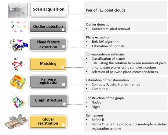
In this section, we first describe the general prerequisites for TLS scans acquisition and preprocessing with a brief description of plane segmentation using the random sample consensus (RANSAC) algorithm [31]. Then, we present the closed-form registration method that first finds a set of plane correspondences with complex numbers and minimizes the sum of residuals over all such plane correspondences. Finally, the closed-form solution, which uses a set of plane-to-plane correspondences to consistently redistribute the residual errors across the whole project, is presented. In Figure 3, the proposed framework is shown, and the involved steps are illustrated. The details of these steps are explained in the subsequent sections.
3.2.1. Plane Segmentation with the RANSAC Algorithm
Planar surfaces are abundant in human-made environments, and their extraction requires less storage than voxel-grid representations. However, due to the varying point density of TLS data, measurement errors can lead to sparse outliers. These can influence the plane extraction task, and reduce the registration accuracy. To avoid these weaknesses, we start by removing outliers from the raw point cloud () using the statistical outlier removal technique proposed by [32]. The filtered point cloud is obtained based on a statistical analysis of a query point with respect to its surrounding neighbors . Thus, given a filtered reference point cloud and a filtered target point cloud with both inliers and outliers, the RANSAC algorithm is used for plane extraction task. This is done by randomly selecting three non-collinear points in , followed by a voting scheme to find the optimal fitting plane model. The best fit plane is estimated by finding the eigenvector corresponding to the smallest eigenvalue of the covariance of weighted point coordinates, as described in [17].
3.2.2. Estimation of Transformation Parameters from Plane Correspondences
Typically, pairwise registration of point clouds follows a two-step strategy. First, corresponding features are required in overlapping scans, and second, transformation parameters are estimated to align a pair of point clouds relative to each other in a common coordinate system. Our proposed strategy is based on plane correspondences and estimates the rotation and translation parameters separately. Given two sets of segmented planar surfaces and , the transformation from to consists of a 3D rigid motion, as follows:
where denotes the 3D rotation, represents a 3D translation and a point in 3D space. The condition that a point lies on a plane in , where is the normal vector of plane and d its distance to the origin, can be written as [26]:
where u′ is the unit normal vector of the plane and d′ its distance to the origin. By substituting Equation (1) into (2), we can obtain the following expression:
from Equation (3), we have:
note that the rotation from vector to the vector is expressed as:
We now have two separate sets of equations per plane correspondence, one for t, as presented in Equation (4), and one for R, as can be seen in Equation (5). Given a set of putative correspondences, we can estimate the transformation parameters R and t using a closed-form solution. As described by [26], a system of equations can be formed to estimate the parameter t, where and are obtained by stacking and for all plane-to-plane correspondences and contains the residual values. The least-squares solution for t can be obtained as: . The estimate of R is obtained using Horn’s solution [33]. In the subsequent section, we describe our proposed method to find corresponding planes using complex numbers.
3.2.3. Plane Matching with Complex Numbers
In its basic form, the estimation of the transformation parameters relies on the presence of pairs of corresponding planes. Dold and Brenner [34] give a plane matching method for TLS point clouds. They investigated the combinatorial complexity of the search for corresponding planes. Our plane matching algorithm extends this method by adding a false positive detection task. This is done by inferring the relative angle between patch plane vectors using complex numbers. It works in three steps: (1) Classification of the segmented planes; (2) Determination of the rotation between pairs of candidate planes; and (3) Calculation of approximate translation.
• Classifying the segmented planes
First, we assume that the TLS is mounted on a tripod and is levelled using a bubble level. Consequently, planes extracted from TLS data have small deviations from vertical and horizontal planes [35]. Thus, given two sets of segmented planar surfaces and , our algorithm separates these in different classes, i.e., horizontal planes (representing the planes parallel to the floor) and vertical planes (representing the wall planes of buildings) using the third component of the normal vector of or . The horizontal planes are those whose normal vectors and the z axis form an angle smaller than 3 degrees, while the vertical planes are those whose normal vectors and the z axis form an angle larger than 89 degrees. Such classification procedure is essential to reduce the search space, and for the optimization of the matching performance.
• Calculating the rotation between normal vectors of pairs of candidate planes
Second, given a set of segmented planes in both the reference point cloud () and the target point cloud (), as presented in Figure 4a, in order to calculate the rotation angle () between the normal vectors (Figure 4b) of each pair of candidate planes for correspondence (Figure 4c), we propose the use of complex numbers. Figure 4 shows an example of segmented planes, the normal vectors and the relative roation angle between two segmented planes in and .
As shown in Figure 4c, and represent the rotation angles of to and to , respectively, where and are the normals of the pair of segmented planes in and in , and and are the normals of the pair of segmented planes in and in . For vertical planes, we can assume that is only applied around the axis; then, for every pair of adjacent non-parallel vertical planes, we have:
Equation (6) can be rewritten as:
where is the rotation matrix in the plane.
For all angles , the matrices form a special orthogonal group . All rotation in the plane can be represented by a complex number. Then, the rotation in the plane of a vector can be rewritten by the multiplication of complex numbers, as follows [36]:
where . Thus, the complex number can be calculated by multiplying Equation (8) by the inverse of the complex number , as follows:
Then, the rotation angle between and can be calculated using the following expression:
Subsequently, the algorithm checks the correspondence for every two pairs of non-parallel vertical planes calculating the difference between their relative angle (), as follows:
The pseudo-correspondences between the two pairs of non-parallel vertical planes are established if , otherwise, the correspondence hypothesis is rejected. Please note that, to avoid the singularity problem, the planes must be non-parallel vertical planes, since vertical planes are influenced by the rotation of the TLS sensor.
• Selection of pairwise plane correspondences
In the third step, the components and are calculated using the pairs of corresponding non-parallel vertical planes. For this step, we can reduce the search space by initially assuming that . Thus, we can use two corresponding planes to estimate an approximation of and , as follows:
which can be further decomposed to:
where , , , and . The solution for Equation (13) is given as follows:
An issue which requires attention in this solution is the correspondence between non-parallel vertical planes. The choice of parallel vertical planes can lead to an inconsistent system of equations with no solution. Similarly, the solution for component is obtained using the third pair of corresponding non-parallel vertical planes, as follows:
where and are parallels to the axis. Next, all pairs of vertical planes considered as pseudo-corresponding are combined to find the correct correspondences. This is done by using the approximated translation values and the rotation angle, as follows:
where is the rotation angle from normal vector in to the combined normal vector in , and are the perpendicular distances between the origin of the coordinate system and the combined planes, respectively.
For values less than a predefined threshold and for the smallest value, the pair of corresponding planes is added to the set of pseudo-correspondences with respect to the planes and . Then, the two steps of rotation angle estimation and the approximated estimation of and components are repeated using other planes and a new set of pseudo-corresponding planes is found. The combinations inserted in this set are regarded as true correspondences. In addition, the third component of translation parameters () is recalculated using corresponding horizontal planes. Thus, pairs of pseudo-corresponding horizontal planes are combined to find the correct correspondences using the following expression:
When is less than a predefined threshold, the pair of corresponding horizontal planes is added to the set of pseudo-correspondences with respect to the planes . The combinations inserted in this set are also regarded as true correspondences. After all verifications, the potential corresponding planes are used to refine the translation parameters.
3.2.4. Proposed Global Plane-to-Plane Refinement Solution
Due to the accumulated residual errors resulting from the consecutive pairwise registration steps, a global refinement task should be used to minimize the loop closure error across all scan pairs in the project [14]. Given a discrete set of putative pairwise registrations, we develop a global refinement solution based on a plane-to-plane approach. The global refinement is done with the help of a pose-graph structure.
According to [37], a graph is formed by nodes () and edges (), where nodes represent the pose of each point cloud and edges denote each pairwise registration (transformation of pairs points cloud) with sufficient mutual overlap. An example of a graph structure is shown in Figure 5. The variables denote point clouds and the each pairwise registration are represented by transformation parameters (rotation) and (translation) between the point clouds and , respectively, with .
• Global refinement of rotation parameters
The rotation parameters are globally refined () using our previous work [26], as follows:
where represents the 3D rotation matrix from node to the node (reference) and denotes the 3D rotation matrix from to with and , ,, (see Figure 4). Using quaternions, Equation (18) can be rewritten as follows:
where represents the 3D rotation matrix from node to the node (reference) and denotes the 3D rotation matrix from to and is the residual error, with . Thus, Equation (19) is rewritten as follows:
where is a 4 × 4 matrix associated with left product of the quaternion , , and are 4 × 1 vectors that represent the quaternions , and , respectively. Equation (20) can be rewritten as follows:
where represents a matrix formed by partial derivatives with respect to all components of , is the column vector formed by concatenation of all matrices and , is the number of the nodes and denotes the number of the edges on the graph. Then, the total least square method [38] can be used to estimate the matrix (or ), as follows:
Thus, the matrix that minimizes the Equation (22) is the eigenvector corresponding to the smallest eigenvalue of the matrix . To obtain it is essential to normalize each . As this solution is direct, it does not require initial approximations.
• Proposed global refinement of translation parameters
By combining a pair of point clouds, a difference between two sensor poses and can be obtained, as follows:
where represents the globally refined rotation parameters, is the 3D translation vector from node to , is a column matrix that represents the 3D position of the node with and is a column matrix that represents the 3D position of the node . As described, the translation parameters can be estimated from plane correspondences:
where denotes the normal vector from segmented plane and its perpendicular distance from the origin, and the distance from the origin to plane . Multiplying Equation (24) by and substituting it into Equation (23) yields:
For each pair of point clouds within the network, the proposed method calculates the residual errors based on plane-to-plane correspondences. As the Equation (25) is linear with respect to the sensor positions , ,, and assuming that is the vector of observations and is the normal vector for all plane-to-plane correspondences, respectively, the solution can be globally refined using the least squares method (LSM). Thus, the set of liner equations can be formed to estimate the sensor positions, where is the coefficient matrix containing the partial derivatives in Equation (25), is the vector of constants containing for all plane-to-plane correspondences and is the residual vector. The least-squares solution for can be obtained as: . Please note that the proposed method has been adapted to use plane parameters to estimate ,, , instead of feature points as used by [15]. To obtain a solution, at least four pairs of corresponding planes are needed. Fortunately, this is not a major issue in urban environments, since a large number of planar surfaces are available.
4. Experiments and Results
First, the plane matching method is evaluated in terms of matching success rate (SR), by simply counting the number of correctly matched planes over all pairs of point clouds and the matching time (MT). Its performance also is compared to the K-4PCS registration algorithm [6], which is available in the point cloud library (PCL) [39]. Secondly, the global refinement method is evaluated in terms of mean registration accuracy. The residual root means square errors (RMSE) before and after global refinement are calculated based on the plane-to-plane distances between the corresponding planes. The performance of the proposed global refinement method is evaluated by comparison with three other approaches. The first is a combination of iterative closest point algorithm [1] and the global refinement method proposed by Lu and Milios [15]. The second approach is the global registration using our pipeline but omitting the global refinement of the rotation parameters. The third approach is the global registration proposed by Theiler et al. [14]. The first approach is available in the point cloud library (PCL) [39], while the source code from the third approach can be found in [40].
4.1. Pre-Processing Data
For all the datasets, the outliers were detected and removed using the statistical outlier removal algorithm. With the removal of the outliers, the number of points contained in the point clouds was reduced by 25%. Basically, this step of the method removes from the data sample all points outside the interval . In this paper, the values assumed for the variables = 0.050 m (mean distance between neighbouring points) and (restriction factor) were determined empirically and were those that best represented the expected sampling of the object on the surface. The surface planes were extracted with RANSAC algorithm using a distance threshold 0.01 m, and 100 iterations. Figure 6 shows an example of the segmented planes for pairs of point clouds obtained by using the RANSAC algorithm. As can be seen, ground planes could not be correctly classified because small inclinations exist due to the different ground levels in all scanned regions. However, this issue does not affect the performance of the matching algorithm.
The planes were classified and segmented into horizontal and vertical planes, with their normals and perpendicular distances calculated with respect to the origin. The and threshold values were respectively 0.15 and 0.01 m for Patio batel and Lape datasets, while for the Royal exhibition building dataset, the value 0.01 m was used for and .
4.2. Experimental Evaluation
4.2.1. Plane Matching Evaluation
As previously mentioned, we tested our plane-based matching algorithm against the K-4PCS algorithm proposed by [6]. For the tests conducted with K-4PCS, we used the following matching algorithm and parameter settings: 3D scale feature transform (SIFT) algorithm for keypoints detection, and voxel size mm, respectively. Table 2 shows the results obtained with both our plane-based matching algorithm and the K-4PCS method. For the “Patio batel” dataset, a sufficiently large number of corresponding planes was obtained for the pairs of point clouds containing salient structures. For these pairs of point clouds, the method achieves high SR (>80%). The SR is generally high for point clouds with large overlap (about 40%). The lower SR for a few of the pairs is due to the smaller overlap (30%) and the high degree of symmetry of planar surfaces in the scene, which reduces the chance for finding correct matches. Table 2 also shows the metric accuracy of the estimated transformation parameters represented by the root mean square error between true correspondences (RMSER). The RMSER obtained with the K-4PCS algorithm is about 0.60 m, while our method achieved a RMSER around 0.40 m. Probable reason for a large RMSER value found is the lower overlap between the pairs of point clouds. Note also that both algorithms use plane correspondences, instead of targets. Thus, to improve the pairwise registration accuracy is necessary to apply the global refinement.
For the “Lape” dataset, the proposed plane matching has been carried out with the optimal parameters, and , set to 0.15 m and 0.01 m, respectively. From the test area, nine evenly distributed corresponding pairs of planes were found, which indicates a matching success rate above 75% (see Table 2). The reason for the moderate success rate is the high number of parallel planes discarded by the proposed plane matching algorithm to avoid shift errors. For the “Royal building exhibition” dataset, the optimal parameters are set to 0.01 m for both the planimetric and altimetric values. This setting is based on the overlap area between the point clouds: where for larger overlaps smaller values for the parameters are used. As can be observed, the reference and target point clouds are well registered. The mean SR for both the experiments is around 95%, as shown in Table 2. However, some failed cases with a large degree of scene symmetry occur. The results of the successful cases reveal that our proposed plane matching algorithm works well. For plane pairwise registration methods, the translational errors are larger than rotational errors due the estimate of normal vectors. Errors of orientation from normal vectors should produce large translation errors. For these experiments, the results reveal that the pairwise registration obtains an RMSE higher than 0.3 degrees and 0.2 m for the rotation error and translation error, respectively. As can be observed in Table 2, the K-4PCS achieve highest matching SR; however, the matching time is considerably higher. Examples of the results obtained with our proposed pairwise registration method can be seen in Figure 7.
4.2.2. Global Refinement Evaluation
As previously mentioned, for comparisons with state-of-the-art research, the renowned global refinement approach presented by [15] and the approach of Theiler et al. [14] are introduced. The results of the 3D globally consistent point clouds obtained with the proposed method can be seen in Figure 8.
Figure 9 shows the mean residual RMSE obtained for each dataset using the proposed method and the baseline approaches. The RMSE values shown that the proposed global refinement method achieves more accurate results than both the method of [15] and omitting the global refinement of the rotation parameters. It can also be seen that scans with more geometric constraints (plane correspondences with other scans) are registered more accurately after global refinement. The lowest registration accuracy is obtained for sensor poses III and VIII which have fewer corresponding planes.
Figure 10 shows the RMSE value of the registration before and after the global refinement. As expected, the proposed global refinement method significantly reduces the misalignments. After the global refinement we achieved accuracies better than 8 cm, that is close to the expected measurement accuracy of the scanning device.
4.3. Discussion
The proposed point cloud registration algorithm involves three prerequisite algorithms, including outlier removal, plane segmentation, and plane-based matching. The complexity of the proposed algorithm is centred on the plane-based matching algorithm. In practice, by calculating using the dot product of the two normal, only internal angles are verified, because such a process is limited to the interval from 0 to 180 degrees, producing ambiguity between the angles. However, a normal vector can be rotated from −180 to 180 degrees, that is, internal angles and external angles should be verified. To overcome this limitation, we use complex numbers to find the angle between the normal vectors of each pair of candidate planes referencing to the point at which this plane is rotated. Using complex numbers helps to avoid ambiguity between the angles through an analysis of the quadrants (see Equation (11)). Note also that we constraint the sign of the parameter d to be positive to orient all towards the viewpoint. Using complex numbers to calculate the rotation angles between adjacent non-parallel vertical planes, we can decrease the number of mathematic operations comparisons with matrix operations. For the plane-based matching algorithm, plane extraction and manual setting of parameters is mandatory, as these arguments reduce the number of false positives and the number of candidate features. A close inspection of false-positive detection step revealed that the proposed plane-based mathing algorithm can reduce the number of false positives about 79%. As expected, failure cases are caused by the symmetry of the scenes, which are often in the indoor areas. As limitations of the plane-based scheme, we can point out the requirement for horizontal and vertical planes. Although surface planes are abundant in urban scenes, the behavior of the proposed strategy is not consistent for forest environments and under occlusion or very low overlap. The pairwise registration performance is better with high valid overlapping area such as for indoor environments. However, indoor environments remind us that parallel planes will increase the risk of failure for the proposed plane matching algorithm. In light of the proposed plane-based matching algorithm a minimum of three non-parallel pairs of correct plane correspondences must be found at the matching step. Fortunately, this is not a major issue in man-made environments (e.g., cities) and indoor environments that can be used in several applications, such as indoor navigation, infrastructure inspection, façade 3D modelling, cultural heritage documentation, mapping, augmented reality, 3D modelling of industrial objects, and others. With respect to the matching performance, as the rotation of the TLS is around z axis, the horizontal planes are less influenced by rotation of the TLS, while vertical planes are influenced by the rotation of the TLS. Thus, we assume that horizontal planes are those whose normal vectors and the z axis form an angle smaller than 3 degree and vertical planes are those whose normal vectors and the z axis form an angle larger than 89 degree. This is essential for reducing the search space, and for the optimization of the matching performance. As a direct consequence of the TLS scans, different plane parameters may be obtained from different views. As a result, the plane-based registration is influenced by the plane extraction accuracy. The parameter is defined as a function of the (normal plane) and point coordinates, while the precision of plane fitting is dependent on both the noise level of the points and the choice of the coordinate system, as presented by [28]. Since the estimation of translation parameter () in the plane-based solution is dependent on the d parameter of the noisy planes, a solution is normalized point coordinates to improve the estimate of parameter in plane fitting, and consequently uses the variance of in plane fitting to improve the estimate of translation parameters () during the pairwise registration solution. However, this has not been tested, and is left for future work.
Compared with other global refinement methods, our method is a closed-form solution and refines both rotational and translational parameters. From our point of view, the refinement of the rotations is essential for the correct refinement of the sensor positions. Thus, as previously mentioned, we first refine the rotations using the approach indicated by [26], while the TLS positions are corrected with our plane-to-plane refinement method. In practice, the pairs of point clouds with lowest overlapping point clouds present worst results for the pairwise registration task and the alignment is not good enough to be refined by our method. To disambiguate the pairwise transformations, geometric constraints should be added in the pose-graph optimization. Moreover, pairs of point clouds that lack salient structures, and contain more occlusions and vegetation present the largest errors. Although our global refinement method is compatible in terms of accuracy compared to the state-of-the-art, it is much faster, corresponding to 55% less computation time, as can be seen in see Figure 11.
5. Conclusions
In this paper, we presented a framework for automatic marker-less registration of multiple terrestrial laser scanner point clouds. First, we introduced a plane-based matching scheme that relies on a new parametrization using complex numbers to find the correspondence between pairs of segmented planes. The RANSAC algorithm is used to segment plane surfaces in TLS data. The segmented planes are then classified into vertical and horizontal planes, and their correspondences are obtained using our proposed plane-based matching algorithm. The key novel aspect of our plane-based matching algorithm is the multiplication of complex numbers based on analysis of the quadrants to avoid the ambiguity in the calculation of the rotation angle formed between normal vectors of adjacent planes. It also is able to reduce the number of mathematic matrix operations during the correspondence task. Secondly, we formulated the global fine registration as a graph-based formulation adapted for plane-to-plane correspondences. The main characteristic of this proposed solution is that the refinement of TLS positions by treating the 3D points and their corresponding surface normal as observations. By globally refining the rotation parameters and the translation parameters, TLS position can be accurately obtained. Since our global registration method is non-iterative, multiple point clouds can be quickly registered. In our results, we demonstrated the potential of our method in registering point clouds of outdoor and indoor urban environments with reasonable overlapping. Future work involves conducting additional experiments using dataset of different sources, i.e., photogrammetry and RGB-D data. In addition, the loop closing detection can be executed automatically.
Author Contributions
Conceptualization, N.L.P. and D.R.d.S.; Formal analysis, N.L.P. and D.R.d.S.; Methodology, N.L.P. and D.R.d.S.; Resources, D.R.d.S. and K.K.; Validation, N.L.P. and D.R.d.S.; Writing—original draft, D.R.d.S.; Writing—review & editing, K.K. All authors have read and agreed to the published version of the manuscript.
Funding
This work was supported in part by the CNPq (Conselho Nacional de Pesquisa e Desenvolvimento) under Grant no. 303432/2016-0”.
Acknowledgments
The authors are very grateful to the Mario Reis at the Federal University of Rio Grande do Sul and Kourosh Khoshelham at the University of Melbourne who collected theTLS data for the use of the study area.
Conflicts of Interest
The authors declare no conflicts of interest.
References
- Besl, P.; Mckay, N.D. A method for registration of 3-D shapes. IEEE Trans. Pattern Anal. Mach. Intell. 1992, 14, 239–256. [Google Scholar] [CrossRef]
- Huber, D.; Hebert, M. Fully automatic registration of multiple 3d data sets. Image Vis. Comput. 2003, 21, 637–650. [Google Scholar] [CrossRef] [Green Version]
- Barnea, S.; Filin, S. Keypoint based autonomous registration of terrestrial laser point-clouds. ISPRS J. Photogram. Remote Sens. 2008, 63, 19–35. [Google Scholar] [CrossRef]
- Rusu, R.B.; Blodow, N.; Beetz, M. Fast point feature histograms (FPFH) for 3D registration. In Proceedings of the IEEE International Conference on Robotics and Automation (ICRA), Kobe, Japan, 12–17 May 2009; pp. 3212–3217. [Google Scholar]
- Weinmann, M.; Hinz, S.; Jutzi, B. Fast and automatic image-based registration of TLS data. ISPRS J. Photogram. Remote Sens. 2011, 66, S62–S70. [Google Scholar] [CrossRef]
- Theiler, P.W.; Wegner, J.D.; Schindler, K. Keypoint-based 4-points congruent sets–automated marker-less registration of laser scans. ISPRS J. Photogram. Remote Sens. 2014, 96, 149–163. [Google Scholar] [CrossRef]
- Dong, Z.; Yang, B.; Liang, F.; Huang, R.; Scherer, S. Hierarchical registration of unordered TLS point clouds based on binary shape context descriptor. ISPRS J. Photogram. Rem. Sens. 2018, 144, 61–79. [Google Scholar] [CrossRef]
- Xiao, J.; Adler, B.; Zhang, J.; Zhang, H. Planar segment based three-dimensional point cloud registration in outdoor environments. J. Field Robot. 2013, 30, 552–582. [Google Scholar] [CrossRef]
- Ge, X.; Wunderlich, T. Surface-based matching of 3D point clouds with variable coordinates in source and target system. ISPRS J. Photogram. Rem. Sens. 2016, 111, 1–12. [Google Scholar] [CrossRef] [Green Version]
- Al-Durgham, M.; Habib, A. A framework for the registration and segmentation of heterogeneous lidar data. Photogram. Eng. Remote. Sens. 2013, 79, 135–145. [Google Scholar] [CrossRef]
- Cheng, X.; Cheng, X.; Li, Q.; Ma, L. Automatic registration of terrestrial and airborne point clouds using building outline features. IEEE J. Sel. Top. Appl. Earth Observ. Rem. Sens. 2018, 11, 628–638. [Google Scholar] [CrossRef]
- Xu, Y.; Boerner, R.; Yao, W.; Hoegner, L.; Stilla, U. Pairwise coarse registration of point clouds in urban scenes using voxel-based 4-planes congruent sets. ISPRS J. Photogram. Remote Sens. 2019, 151, 106–123. [Google Scholar] [CrossRef]
- Ji, Z.; Song, M.; Guan, H.; Yu, Y. Accurate and robust registration of high-speed railway viaduct point clouds using closing conditions and external geometric constraints. ISPRS J. Photogram. Remote Sens. 2015, 106, 55–67. [Google Scholar] [CrossRef]
- Theiler, P.W.; Wegner, J.D.; Schindler, K. Globally consistent registration of terrestrial laser scans via graph optimization. ISPRS J. Photogram. Remote Sens. 2015, 109, 126–138. [Google Scholar] [CrossRef]
- Lu, F.; Milios, E. Globally consistent range scan alignment for environment mapping. Autonom. Robot. 1997, 4, 333–349. [Google Scholar] [CrossRef]
- Bornnmann, D.; Elseberg, J.; Lingmann, K.; Nüchter, A.; Hertzberg, J. Globally consistent 3D mapping with scan matching. Robot. Auton. Syst. 2008, 56, 130–142. [Google Scholar] [CrossRef] [Green Version]
- Yang, J.; Li, H.; Jia, Y. Go-ICP: Solving 3D registration efficiently and globally optimally. In Proceedings of the 2013 IEEE International Conference on Computer Vision, Sydney, NSW, Australia, 1–8 December 2013. [Google Scholar]
- Kuemmerle, R.; Grisetti, G.; Strasdat, H.; Konolige, K.; Burgard, W. g2o: A general framework for graph optimization. In Proceedings of the 2011 IEEE International Conference on Robotics and Automation, Shanghai, China, 9–13 May 2011; pp. 3607–3613. [Google Scholar]
- Lourakis, M.A.; Argyros, A. SBA: A Software Package for Generic Sparse Bundle Adjustment. ACM Trans. Math. Softw. 2009, 36, 1–30. [Google Scholar] [CrossRef]
- Wang, S.; Sun, H.Y.; Guo, H.C.; Du, L.; Liu, T.J. Multi-View Laser Point Cloud Global Registration for a Single Object. Sensors 2018, 18, 3729. [Google Scholar] [CrossRef] [Green Version]
- McDonagh, S.; Robert, F. Simultaneous registration of multi-view range images with adaptive kernel density estimation. In Proceedings of the IMA 14th Mathematics of Surfaces, Birmingham, AL, USA, 11–13 September 2013. [Google Scholar]
- Zong-ming, L.; Yu, Z.; Shan, L.; Han-qing, Z.; Dong, Y. Closed-loop detection and pose optimization of non-cooperation rotating targets. Opt. Precis. Eng. 2015, 25, 1036–1043. [Google Scholar] [CrossRef]
- Rusinkiewicz, S.; Levoy, M. Efficient variants of the ICP algorithm. In Proceedings of the Third International Conference on 3-D Digital Imaging and Modeling, Quebec City, QC, Canada, 28 May–1 June 2001; pp. 145–152. [Google Scholar]
- Yang, B.; Zang, Y. Automated registration of dense terrestrial laser-scanning point clouds using curves. ISPRS J. Photogram. Remote Sens. 2014, 195, 109–121. [Google Scholar] [CrossRef]
- Pathak, K.; Birk, A.; Vaskevicius, N.; Pfingsthorn, M.; Schwertfeger, S.; Poppinga, J. Online three-dimensional SLAM by registration of large planar surface segments and closed-form pose-graph relaxation. J. Field Robot. 2010, 27, 52–84. [Google Scholar] [CrossRef]
- Pavan, N.L.; dos Santos, D.R. Global closed-form refinement for consistent TLS data registration. IEEE Geos. Remote Sens. Lett. 2017, 14, 1131–1135. [Google Scholar] [CrossRef]
- Yan, F.; Nan, L.; Wonka, P. Block assembly for global registration of building scans. ACM Trans. Graph. 2016, 35, 1–11. [Google Scholar] [CrossRef]
- Khoshelham, K. Closed-form solutions for estimating a rigid motion from plane correspondences extracted from point clouds. ISPRS J. Photogram. Remote Sens. 2016, 114, 78–91. [Google Scholar] [CrossRef]
- Guo, Y.; Bennamoun, M.; Sohel, F.; Lu, M.; Wan, J. 3D object recognition in cluttered scenes with local surface features: A survey. IEEE Trans. Pattern Anal. Mach. Intell. 2014, 36, 2270–2287. [Google Scholar] [CrossRef] [PubMed]
- Förstner, W.; Khoshelham, K. Efficient and accurate registration of point clouds with plane to plane correspondences. In Proceedings of the IEEE International Conference on Computer Vision Workshops, Venice, Italy, 22–29 Octorber 2017. [Google Scholar]
- Fischler, M.A.; Bolles, R.C. Random Sample Consensus: A Paradigm for Model Fitting with Applications to Image Analysis and Automated Cartography. Commun. ACM 1981, 24, 381–395. [Google Scholar] [CrossRef]
- Rusu, R.B.; Marton, Z.C.; Blodow, N.; Dolha, M.; Beetz, M. Towards 3D Point Cloud Based Object Maps for Household Environments. Robot. Auton. Syst. 2008, 56, 927–941. [Google Scholar] [CrossRef]
- Horn, B.K. Closed-form solution of absolute orientation using unit quaternions. J. Opt. Soc. Am. 1987, 4, 629–642. [Google Scholar] [CrossRef]
- Dold, C.; Brenner, C. Registration of terrestrial laser scanning data using planar patches and image data. Int. Arch. Photogramm. Remote Sens. Spat. Inf. Sci. 2006, 36, 78–83. [Google Scholar]
- Khoshelham, K.; Gorte, B.G. Registering point clouds of polyhedral buildings to 2D maps. In Proceedings of the 3rd ISPRS International Workshop 3D-ARCH 2009: 3D Virtual Reconstruction and Visualization of Complex Architectures, Trento, Italy, 25–28 February 2009. [Google Scholar]
- Stillwell, J. Naive Lie Theory; Springer: New York, NY, USA, 2008. [Google Scholar]
- Grisetti, G.; Kummerle, R.; Stachniss, C.; Burgard, W. A Tutorial on Graph-Based SLAM. IEEE Intell. Transp. Syst. Mag. 2010, 2, 31–43. [Google Scholar] [CrossRef]
- Golub, G.H.; Van Loan, C.F. An analysis of the total least squares problem. SIAM J. Numer. Anal. 1980, 17, 883–893. [Google Scholar] [CrossRef]
- Rusu, R.B.; Cousins, S. 3D is here: Point Cloud Library (PCL). In Proceedings of the IEEE International Conference on Robotics and Automation, Shanghai, China, 9–13 May 2011; pp. 1–4. [Google Scholar]
- ETH Zurich. Department of Civil, Environmental and Geomatic Engineering. Available online: https://prs.igp.ethz.ch/research/Source_code_and_datasets.html (accessed on 4 February 2020).
Figure 1.
Marker position of each dataset. (a) “Patio Batel” dataset, (b) “Lape” dataset and (c) “Royal building exhibition” dataset.
Figure 1.
Marker position of each dataset. (a) “Patio Batel” dataset, (b) “Lape” dataset and (c) “Royal building exhibition” dataset.

Figure 2.
Detailed views of unregistered point clouds. (a–d) “Patio Batel” dataset, (e–h) “Lape” dataset and (i–l) “Royal exhibition building” dataset.
Figure 2.
Detailed views of unregistered point clouds. (a–d) “Patio Batel” dataset, (e–h) “Lape” dataset and (i–l) “Royal exhibition building” dataset.

Figure 3.
The framework of the proposed method.

Figure 4.
The rotation angle between normal vectors of segmented planes. (a) Segmented planes on reference and target point clouds. (b) Normal vectors of the planes in both the reference point cloud and the target point cloud. (c) Rotation angles for a pair of candidate plane correspondences.
Figure 4.
The rotation angle between normal vectors of segmented planes. (a) Segmented planes on reference and target point clouds. (b) Normal vectors of the planes in both the reference point cloud and the target point cloud. (c) Rotation angles for a pair of candidate plane correspondences.

Figure 5.
Illustration of pose-graph. Nodes represent the point clouds, and edges denote the pairwise registration.
Figure 5.
Illustration of pose-graph. Nodes represent the point clouds, and edges denote the pairwise registration.

Figure 6.
Segmented planes pair of point clouds using the RANSAC algorithm correspondent to the Patio Batel dataset. (a) Point cloud I. (b) Point cloud II. (c) Point cloud III. (d) Point cloud IV. (e) Point cloud V. (f) Point cloud VI. (g) Point cloud VII. (h) Point cloud VIII.
Figure 6.
Segmented planes pair of point clouds using the RANSAC algorithm correspondent to the Patio Batel dataset. (a) Point cloud I. (b) Point cloud II. (c) Point cloud III. (d) Point cloud IV. (e) Point cloud V. (f) Point cloud VI. (g) Point cloud VII. (h) Point cloud VIII.

Figure 7.
Detailed views of registered pairs of point clouds. Pairwise registration results of the “Patio Batel” dataset (a)–(c), “Lape” dataset (d)–(f), and “Royal building exhibition” dataset (g)–(i).
Figure 7.
Detailed views of registered pairs of point clouds. Pairwise registration results of the “Patio Batel” dataset (a)–(c), “Lape” dataset (d)–(f), and “Royal building exhibition” dataset (g)–(i).

Figure 8.
3D globally consistent point clouds obtained with the proposed method: (a) “Patio batel” dataset, (b) “Lape” dataset, and (c) “Royal exhibition building” dataset.
Figure 8.
3D globally consistent point clouds obtained with the proposed method: (a) “Patio batel” dataset, (b) “Lape” dataset, and (c) “Royal exhibition building” dataset.

Figure 9.
Comparison of proposed method with three approaches.

Figure 10.
The RMSE of the registration point clouds before and after the global refinement.

Figure 11.
Results of the global registration time for each tested method.


Table 1.
The core specifications of the TLS sensors and outdoor/indoor experiments.
| ID | TLS Sensor | Area (m) | Average Overlap (%) | Mean Point Density Points/m2 | Mean Size (Million Points) | Number of Scans | Environment |
|---|---|---|---|---|---|---|---|
| Patio Batel | Faro LS 880 | 150 × 170 | 45 | 12 | 1.5 | 9 | Urban (outdoor) |
| Lape | Faro LS 880 | 15 × 15 × 3 | 70 | 6 | 2.7 | 4 | Office (indoor) |
| Royal exhibition building | Faro Focus S120 | 70 × 30 × 15 | 70 | 11 | 4.5 | 16 (for each floor) | Building (indoor) |
Table 2.
Evaluation of our proposed plane-based matching algorithm and K-4PCS algorithm.
| K-4PCS | Proposed Plane-Based Matching Algorithm | |||||||
|---|---|---|---|---|---|---|---|---|
| Dataset | #Mean extracted keypoints | Mean SR (%) | Mean MT (s) | Mean of RMSER (m) | # Mean corresponding planes | Mean SR (%) | Mean MT (s) | Mean of RMSER (m) |
| Patio Batel | 16.840 | 98.90 | 995 | 0.60 ± 0.31 | 19 | 84.4 | 200 | 0.38 ± 0.15 |
| Lape | 13.850 | 95.82 | 789 | 0.49 ± 0.24 | 9 | 75.5 | 101 | 0.25 ± 0.11 |
| Royal Building | 25.742 | 99.67 | 1045 | 0.28 ± 0.21 | 35 | 95.2 | 127 | 0.16 ± 0.07 |
© 2020 by the authors. Licensee MDPI, Basel, Switzerland. This article is an open access article distributed under the terms and conditions of the Creative Commons Attribution (CC BY) license (http://creativecommons.org/licenses/by/4.0/).
Share and Cite
MDPI and ACS Style
Pavan, N.L.; dos Santos, D.R.; Khoshelham, K. Global Registration of Terrestrial Laser Scanner Point Clouds Using Plane-to-Plane Correspondences. Remote Sens. 2020, 12, 1127. https://doi.org/10.3390/rs12071127
AMA Style
Pavan NL, dos Santos DR, Khoshelham K. Global Registration of Terrestrial Laser Scanner Point Clouds Using Plane-to-Plane Correspondences. Remote Sensing. 2020; 12(7):1127. https://doi.org/10.3390/rs12071127
Chicago/Turabian StylePavan, Nadisson Luis, Daniel Rodrigues dos Santos, and Kourosh Khoshelham. 2020. "Global Registration of Terrestrial Laser Scanner Point Clouds Using Plane-to-Plane Correspondences" Remote Sensing 12, no. 7: 1127. https://doi.org/10.3390/rs12071127
Note that from the first issue of 2016, this journal uses article numbers instead of page numbers. See further details here.