Technical Note

Diapiric Structures in the Tinto River Estuary (SW Spain) Caused by Artificial Load of an Industrial Stockpile

by
Juan A. Morales
1,*,
Berta M. Carro
1,
José Borrego
1,
Antonio J. Diosdado
2,
María Eugenia Aguilar
1 and
Miguel A. González
3
1
Scientific and Technological Center of Huelva (CCTH), Earth Sciences Department, University of Huelva, 21007 Huelva, Spain
2
Department of Mining Engineering, University of Huelva, Av. 3 de Marzo, S/N, 21007 Huelva, Spain
3
Navíos de Aviso S.L, Av. Andalucía, 9, 21006 Huelva, Spain
*
Author to whom correspondence should be addressed.
Remote Sens. 2024, 16(8), 1465; https://doi.org/10.3390/rs16081465
Submission received: 9 February 2024 / Revised: 11 April 2024 / Accepted: 15 April 2024 / Published: 20 April 2024
(This article belongs to the Special Issue Advances in Remote Sensing in Coastal Geomorphology (Third Edition))

Abstract

:
The mouth of the Tinto River is located on the southwest coast of the Iberian Peninsula in the northwest of the Gulf of Cadiz. The river flows into an estuarine system shared with the Odiel River, commonly known as the “Ría de Huelva”. In the 1960s, a wide area of ancient salt marshes was transformed by a stockpile of industrial wastes of phosphogypsum, reaching a height of 35 m above the level of the salt marsh at its highest point. Two surveys using high-resolution seismic reflection in conjunction with a parametric profiler were carried out in 2016 and 2018. The purpose of these geophysical studies was the realization of a 3D model of the sedimentary units constituting the most recent filling of the estuary. The records present abundant extrusion structures located on the margins of the waste stockpiles, which break the visible stratification of the surficial units of the estuary. In some sectors, these structures have reached the estuarine surface and have, therefore, a morphological expression on the estuarine floor. The origin of these structures is interpreted as a vertical escape of fluidized sediments from lower units caused by overpressure from stacking.

1. Introduction

Coastal systems, and estuaries in particular, are very sensitive to human actions, which can generate imbalances in terms of both hydrogeochemistry and sedimentary dynamics [1]. Regardless of this fact, during the last century and beyond, many industrial enterprises have been located within estuarine systems. In many countries, factories have been located in or near estuaries, where, for decades, they have dumped their liquid and solid discharges, but no reports of deformation of recent and unconsolidated sediments under these wastes were documented in the literature. The Río Tinto Estuary in Spain is one such case. The objective of this study is to analyze, through the use of seismic reflection techniques, the response of estuarine infilling materials on the north bank of the Rio Tinto Estuary to the solid waste piles dumped by one of the factories.

1.1. Location, Dynamics and Anthropic Framework

The Tinto River mouth is located on the southwest coast of the Iberian Peninsula, in the central sector of the Gulf of Cádiz at the southern limit of the city of Huelva. This environment together with the Odiel River mouth forms the estuarine system known as the Huelva Estuary (Figure 1A). From a morphological point of view, this system can be classified as a bar estuary following the criteria of Pritchard [2] and Perillo [1] and, from a dynamic point of view, can be defined as a wave-dominated estuary following the criteria of Dalrymple et al. [3]. This coast presents a semidiurnal and mesotidal character, with an average range of 2.1 m but ranging between 1.70 m at neap tides and 3.06 m at spring tides [4]. The tidal wave propagates inside the estuary following a hyposynchronous pattern. The open part of the estuary is affected by an average swell of moderate energy, with a mean significant wave height of 0.5 m. Atlantic storms from the southwest with wave heights of over 1.5 m can also arrive at the coast. However, in both, fair weather and storm waves act solely in the marine domain of the estuary and do not affect the study area, which is located in the central tide-dominated domain. The coincidence of orientation of the prevailing winds, coming from the SW, and the main channel of the estuary allows the frequent generation of waves inside the estuary, a fact that accelerates the propagation of the tidal wave to the inner estuarine domains and can create surges smaller than 0.5 m. The fluvial discharge of the Tinto River is markedly seasonal with significant interannual irregularity but is practically nil during the summer and periods of drought. The average flow is usually lower than 10 m3/s, although this can exceed 400 m3/s during severe floods.
The strategic location of the estuary, which provides the closest maritime access to the metals of the Iberian Pyrite Belt, led to the development of a large port complex accompanied by a nucleus of chemical and petrochemical industries. Several of these factories, now inactive, were engaged in the production of phosphoric acid for the manufacture of fertilizers. The industrial processing residue consisted of a substance known as phosphogypsum. The dumping of phosphogypsum onto the marshes on the north margin of the Tinto began in 1964 and gradually accumulated in height and extension until it ceased in 2010. During these 46 years, some 120 million tons of waste were deposited in the form of huge stockpiles distributed over an area of 1200 hectares and reaching a maximum height of 35 m over the old marsh surface (Figure 1). The study area is located along the north bank of the Tinto Estuary, bordering the southern margin of the highest stockpile (Figure 1B).
The estuarine depositional record under the stockpiles is composed of six Holocene lithological units (Figure 2A) deposited over Neogene formations of the Guadalquivir Basin [4]. Following the depositional order, the six Holocene units are U1—lower massive muds, U2—lower muddy sands, U3—massive sands, U4—sandy muds, U5—upper muddy sands and U6—root-bioturbated muds. These units display a wedged morphology, with a thickness of up to 30 m in the areas under the estuarine channel, which decreases towards the northern border of the stockpiles (Figure 2B). The morphology of the Holocene units is influenced by the paleotopography of the upper surface of the Neogene formations. The fine lithology of the lower (1 and 2) and upper units (5 and 6) means they function as aquitards, whereas the intermediate units (3 and 4) are mainly constituted by sand and function as a confined aquifer, characterized by high water content and elevated fluid pressure in pores [5].
Figure 2. Geological setting of the stockpiles. (A) Synthetic sedimentary sequence under the stockpiles (Carro et al., 2018). (B) Geological profile showing the geometry of the sedimentary units and record of accumulated subsidence from geological information in previous studies [6,7].
Remotesensing 16 01465 g002

1.2. Current Condition and Hypothesis

A recent study carried out by the same team of authors as the present paper [7] using a multibeam echosounder described various surface features, such as pockmarks, mud volcanoes and bulges. These were interpreted as the possible surface expression of injections of fluidized sediment from deeper layers of the estuarine infill. Other features described in the study were generated by bed erosion resulting from tidal currents or extreme fluvial flows in which the estuarine floor becomes hydrodynamically unbalanced. This imbalance has been attributed to an uplift of the channel bed areas where the supposedly extrusive structures are located.
The interpretations of the previous study were based on the hypothesis that the residues exert load pressure on the estuarine sediments. This overpressure can produce deformations in the sedimentary fill, resulting in subsidence phenomena in the estuarine sediments supporting the stacks [6]. This subsidence can be deduced from the fact that the original surface of the marsh, located at the upper limit of the intertidal area, is now situated more than 8 m below this level at some points under the stockpiles (Figure 2B). Subsequent work using differential synthetic aperture radar interferometry (DInSAR) techniques has shown that today, this subsidence is an active process and was in operation at least over the period 2016–2021 [8], reaching 16 cm/year in areas of the stacks closest to the study area. In parallel, horizontal displacements of some points on the surface of up to 2.5 cm/year have also been observed.
Thus, the working hypothesis is that subsidence under the stacks could have caused a lateral migration of fluidized material from Units 3 and 4 towards the estuarine channel and that this material could have been injected towards the surface at the margins of the stacks where the vertical pressure decreases. In order to test for evidence of such injections, this study carried out an underground analysis in the same area covered by the previous multibeam surficial study.

2. Materials and Methods

The study employed high-resolution seismic reflection using an INNOMAR SES2000 subsurface parametric profiler operating between 6 and 8 kHz (Innomar Technologie GmbH, Rostock, Germany). This sound source achieved a penetration of more than 6 m into the subsoil. The analysis and interpretation of the resulting seismic profiles allowed us to observe the acoustic response and geometry of the most recent lithological units (U3, U4 and U5), as well as the internal geometry of these units and their deformations. The seismic equipment was connected to a Trimble AgGPS332 positioning system with differential corrections (dGPS) implemented by an OmniSTAR HP module (Trimble Inc. Westminster, CO, USA). The measuring system was installed and operated from a navigating boat.
In order to observe whether the structures were active and undergoing displacement, two surveys separated by 15 months were carried out (December 2016 and March 2018). The surveys consisted of carrying out 11 longitudinal seismic profiles parallel to the alignment of the southern edge of the stockpile and to the main channel of the estuary (Figure 3). The layout of the profile tracks was the same in both surveys. These campaigns were carried out with the ship and technical support of the company Navíos de Aviso SLU.
To identify the different acoustic responses to the sedimentary facies, 7 vibracores were extracted along the intertidal zone of the southern margin of the pool (Figure 3). A vibracore is a type of sounding obtained by vibration applied to an aluminum pipe. These were taken following the method set out in [9]. The length of these cores was close to 5 m, reaching a thickness of sediment similar to the depth reached by the seismic records.

3. Results

The main results of this work are based on the link between seismic facies and sedimentary facies, which allows for a reconstruction of the geometry of sedimentary bodies and structures.

3.1. Seismic Facies

Seismic facies is a term used to refer to the set of properties observable in a seismic profile to differentiate lithoseismic units. These properties are the configuration, amplitude, frequency, continuity and speed of the seismic waves when passing through a lithological unit [10]. In short, seismic facies describe the acoustic reflection characteristics of the sediments. The seismic records obtained in this study enabled two seismic facies to be differentiated (Figure 4).
The upper seismic facies (SFU) was the more surficial of the defined facies. It was characterized by several parallel, closely spaced reflectors without any significant sharp unconformities. The top of this facies was the estuarine bed, while the base formed a well-defined boundary with the second seismic facies.
The lower seismic facies (SFL) corresponded to a poorly defined and transparent seismic record, which extended from the base of the SFU to the lower limit of the record.

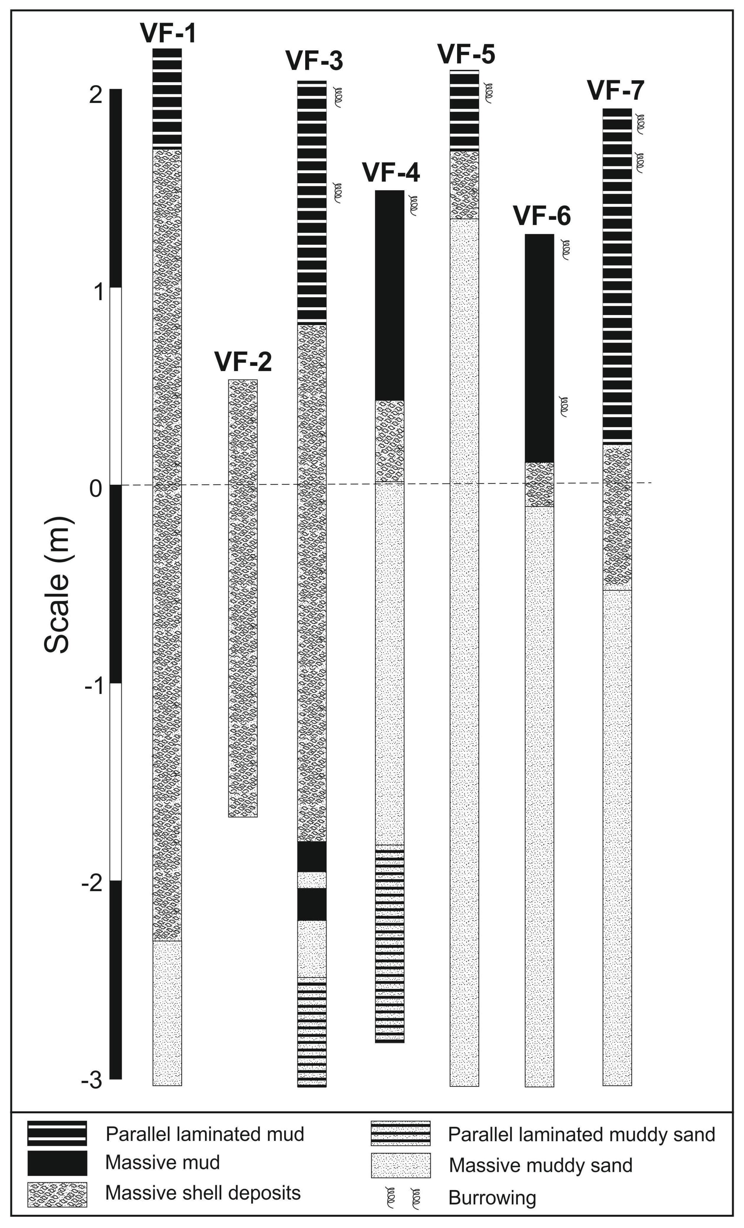
3.2. Sedimentary Facies

The seven vibracores (Figure 5) enabled direct observation of the sedimentary facies corresponding to the two seismic facies described above. In general terms, five sedimentary facies can be characterized: parallel laminated muds, massive muds, parallel laminated muddy sands, massive muddy sands and massive shell accumulations.
The parallel laminated muds consisted of clayey silts with alternating sheets of dark gray and light gray or reddish-brown. The different colors in the sheets corresponded to their organic matter content, the darker colors being attributable to a higher carbon content. These facies were often partially bioturbated by annelids, bivalves or crustaceans and also may contain scattered bivalve shells.
The massive muds consisted of metric strata of dark gray clayey silts that were also occasionally highly bioturbated by the aforementioned organisms. Some millimetric intercalations of fine or very fine sand could also be found in these muds. The upper part of the sediment cores always contained parallel laminated and massive muds.
The parallel laminated and massive muddy sands corresponded to bodies several meters thick that either had a homogeneous fabric or presented parallel laminations marked by the intercalation of centimetric layers of a muddy nature. These facies occupied the lower part of the northernmost vibracore sequences.
The massive shell accumulations were mainly constituted from Ostrea edulis and Crassostrea angulata shell accumulations, with a muddy matrix and a clast-supported fabric. Generally, the main parts of the clastic elements were isolated valves, but in a very small number of cases, entire individuals could also be observed. In any case, there were no individuals in life positions, and consequently, the suggestion that the facies was a biohermic bank could be discarded. In the northernmost cores, these facies were found in a layer several decimeters thick, separating the upper muddy facies from the lower sandy facies, while in the southern cores, they formed much thicker bodies in excess of 2 m (cores VF-1, VF-2 and VF-3).
The parallel laminated and massive muds corresponded to the SFU acoustic facies, whereas the sandy muds and shell accumulations constituted the SFL acoustic facies. Regarding the relationship of these facies to the general sequence described above (Figure 2), it is interesting to note that the parallel and massive muds (and consequently SFU) corresponded to estuarine Unit 5 above, while the shells and muddy sands (and hence SFL) corresponded to estuarine Unit 4.

3.3. Geometric Relationships

Parallel disposition relationships between the facies similar to that shown in Figure 4 were observed only in the profiles furthest away from the tailing ponds. In contrast, the most widely observed structures were ascent plumes and diapirs, which developed on the margins of the stockpiles (Figure 6).
Plumes are simple extrusions with a metric diameter and little vertical displacement. In the seismic records, they can be observed to have a parabolic shape (Figure 6A). They are composed of fluidized sediment from the SFL and deform the base of the SFU, although some can also be observed inside the SFU. This phenomenon can be interpreted as injections of liquid that internally deform the mud sheets comprising this unit.
Diapirs are more developed extrusive structures and have larger dimensions than plumes. These structures are upward injections of the SFL that clearly cut the horizontal reflectors of the SFU, deforming them at their contact edges. Their diameter can reach several tens of meters, and they have more than 3 m of vertical migration (Figure 6B). The most evolved diapirs are more than 20 m in diameter, and their vertical displacement exceeds 4 m, completely cutting through the SFU and reaching the surface (Figure 6C). In these cases, the seismic profiles show the surface to be deformed. This bulge is due to the extrusion of material and coincides with the area where mud volcanoes have been observed on the surface.
The maximum expression of the extrusive deformation of the SFL is the presence of a large dome of this material that has displaced the SFU, causing it to become completely eroded and dismantled. This dome is located at the southwestern end of the raft margin (Figure 6D) and is constituted by the metric accumulation of the shelly facies observed in cores VF-1, VF-2 and VF-3 (Figure 5).
The particular distribution of the injections shows the dimensions and deformation of these structures increasing from northeast to southwest.

3.4. Dynamics and Evolution

Field surveys carried out in December 2016 and March 2018 traced the same navigation lines in order to compare the records and determine whether any visible displacement of the plumes or the diapirs had taken place. In both cases, clear displacements were observed. Some plumes rose between 0.5 and 1 m in the 15 months between the two surveys (Figure 7A).
Movements were also observed in the diapirs, but in this case, the displacements were less than 20 cm, apart from in exceptional cases (Figure 7B). It can also be observed that the ascent of diapirs deforms the levels of the different lithofacies constituting the upper seismic unit (red arrow in Figure 7B).
In addition to the evolution of sediment injections, changes in the bed surface can also be observed. In some sections, the erosion of the upper sedimentary layers is clear, as in the case of Figure 7A, where the layers located above the bolder upper reflector appear to have thinned in March 2018.

4. Discussion and Conclusions

The storage of phosphogypsum as a stockpile on the surface of an ancient salt marsh over a period of more than four decades (from 1964 to 2010) meant an increase in the pressure exerted by the materials on the underlying estuarine units, causing subsidence [8]. A recent study analyzed the surficial structures of the estuary channel along the southeastern side of the piles using multibeam echosounder techniques [7]. The study revealed the presence of different-shaped fields: pockmarks, mud volcanoes and bulges. These structures were interpreted as a possible result of the combination of sediment deformations and erosion by tidal currents in response to the overpressure caused by the stockpiling of industrial waste. Nevertheless, this interpretation remained to be demonstrated until seismic records provided evidence of these deformations. The present paper provides these subsoil data.
The analysis of the deformation structures observed in the seismic records allows us to distinguish plumes of liquefied sands, diapirs and domes. The plumes represent minor deformations, and their presence is more frequent in the northeastern margins of the piles. The location of these structures coincides with the pockmarked field observed by Carro et al. [7]. Diapirs are larger-scale deformation structures that occupy the central part of the study area. These can reach up to 100 m on the surface, with more than 5 m of vertical displacement. A curious thing is that the diapiric structures can be observed at different stages of development, from deep to breaching the surface. In places where diapirs reach the surface, mud volcanoes have been observed. The large domed structures appear in the SW sector of the study area. These domes can exceed 300 m in length and rise more than one meter above the bed of the estuary. The dome structures coincide with the bulge field identified by Carro et al. [7] at the bed of the channel.
The different injection structures described present a gradation that could be interpreted as different stages in the loss of fluid from the lower units (Figure 8). In this conceptual model, the incipient deformation is represented by the plumes, in which the water contained in the pores escapes through the upper units (Figure 8A). In a more advanced stage of evolution, due to higher fluid pressures, an injection of fluidized sediment can occur, forming the deep diapirs, which do not present significant vertical development but sometimes grow sufficiently to deform the horizontal stratification of the upper layers (Figure 8B). With more advanced deformation, the diapirs reach the surface, which can be observed as an expulsion of fluidized sediment to the exterior in the form of mud volcanoes (Figure 8C). Finally, the massive diapirs attach to each other to constitute a large dome, the surface expression of which takes the form of a bulge (Figure 8D).
Some authors [11] related the mud volcanoes to the diapirs, considering a submarine mud volcano as the surficial expression of the underground structure from which mud and fluid vertically flow and erupt. The combination of deep structures and surface shapes described in this paper is consistent with what has been described by other authors [11,12,13]. According to these authors, some diapirs and other sediment injection structures can rise from the deep subsurface without breaching the surface, while other structures break through the upper layers and reach the exterior. Mud volcanoes are the expression of fluidized sediment eruption at the seafloor. In the case of dome creation, the upper unit is elevated in such a way that it causes a restriction in this section of the estuarine channel, leading to an acceleration in the currents, which ends up completely eroding the unit. It was described how the presence of these structures exerts a significant influence on the interaction of the bed morphology with the water masses [14]. In this type of restricted coastal environment, this factor becomes even more significant because the rise of the floor strongly controls the estuarine hydrodynamics.
The combination of multibeam echosound and vertical seismic records (Figure 9) shows perfect agreement with respect to the surficial forms of the bed floor and the deformation structures described. In this 3D scheme, it can be seen how the less evolved injections (plumes and pockmarks) are found towards the NE, while the more evolved ones (domes and bulges) are located in the SW region, with the diapirs located in the central area. This indicates that the deformation began earlier in the SW region, and that is why the structures that present greater deformation are observed there.
The piling of 35 m of industrial waste on the marsh surface in just 40 years has doubled the load supported by the sediments of the lower units of the estuarine fill [7]. As a consequence of this sudden increase in load, the surface of the old marsh has undergone more than 8 m of subsidence at some points, as has been observed in several surveys [6,15]. This subsidence necessarily implies a deformation of the sedimentary units deposited under the stockpiles.
The Neogene formations located under the stockpiles present some faults (observable in Figure 2B). Recent studies have shown that these faults were active until only a few thousand years ago [16,17]. The weight of the stockpiles could activate these faults again and, in fact, their movement could explain part of the observed subsidence. Furthermore, another part of the subsidence could be absorbed by a compression of the aquifer sands of Unit 3, which are extruded laterally towards the margins of the piles where the vertical pressures are lower. In this sense, lateral mass flow has been cited in this regard as a subsidence mechanism [18]. The presence of diapirs on those margins of the piles that have experienced the greatest subsidence indicates that the lower units in the estuarine side of the stockpile (composed of sandy mud and muddy sand) were liquefied and injected vertically.
From a methodological point of view, a very similar approach, using three-dimensional seismic profiles and multibeam data, was adopted in a deep analysis of the Pearl River mouth in the North China Sea [19]. This study revealed numerous fluid injection features and associated shallow gas extrusions over several kilometers. In our case, the structures described have been interpreted for the first time as the result of the vertical migration of fluids and fluidized sediments due to overpressure from a pile of industrial waste. However, these structures present morphologies similar to those observed on some continental platforms and are attributed to gas and water extrusions (e.g., [20,21,22,23,24,25,26]). Milkov [27] was the first to consider the extrusion of fluids as a generic phenomenon, adding that these fluids are usually gases but could also be water, brines or oil. The work also systematizes the possible causes that generate the rise of fluids, considering geological, tectonic, geochemical and hydrogeological causes, among which the pressure from superficial sedimentary stacking is included. Other authors like Kopf also describe these structures as resulting from the rise of fluidized sediments affected by overpressure [12]. Both Milkov and Kopf described cases of high sedimentation rates on continental margins related to various geological contexts but mainly associated with convergent plate boundaries. There are also abundant multidisciplinary studies carried out in the Gulf of Cadiz and the Mediterranean Sea (e.g., [28,29,30]) focused on identifying and describing these underwater structures. In a very different context, other authors interpret some kilometric diapirs located in a tectonically inactive basin in northern Calabria [28]. However, they attribute a similar genesis to many other mud diapirs from volcanic provinces of the Mediterranean with active tectonics [31,32,33].
Other extrusions common in natural environments are salt diapirs. This type of extrusion has been observed in several basins worldwide (e.g., [34,35,36]) and can be described in terms of the halokinetic movements, which depend on the dimensions and geometry of the salt strata and the thickness and nature of the sedimentary sequence deposited above the salt bodies [37]. The dynamics of the main part of these diapir structures seem to be related to compressive tectonic phenomena rather than to the sedimentary load. On the other hand, the movement of these diapirs is usually slow because the salt behaves like a ductile plastic fluid [38]. Some authors have developed models of the dynamics of salt diapirs that accurately reproduce field observations [39]. These models show how rising salt pressure creates a bulge over the diapir. This uplift arches over the overlying sediments, which eventually erode and disperse. This dynamic turns out to be very similar to what was observed in the diapirs described in this study, although the speed of the process characterized in the model is noticeably slower.
Despite the similarities, the scale of the structures described in this work is significantly smaller than both mud and salt diapirs. All the cases described in the bibliography have dimensions of several hundred meters and even kilometers in contrast to the structures of only tens of meters described in the present work. On the other hand, without exception, all these authors cited natural cases in active inner estuarine zones. Nevertheless, the rest of the process suggested in the literature is totally compatible with the interpretation suggested in this paper. The stacking of industrial waste in stockpiles is very common worldwide. Specifically, there is a widespread distribution of phosphogypsum ponds around the world. Consolidated tailing stockpiles have been described as a cause of subsidence in mining contexts. In the case of a mine located in the Great Lakes region of North America, active subsidence was documented under a pile of minerals due to the lateral flow of glacial sediments. This caused sinkage of about 2 m over a period of decades [40]. However, there has never been a documented case of land subsidence in estuarine sediments under a stockpile due to their load. Neither has there been documented the presence of fluid or fluidized sediment escape structures in response to this subsidence. This case shows that, in the future, the subsoil on which stockpiles of this type will be located must be studied in detail before carrying out deposits.
This process will continue to be active for as long as the load is maintained and the fluidized material remains under the stockpiles. It is thus foreseeable that subsidence will continue to occur at a rate of the same magnitude. However, it must be taken into account that the study is located in a seismic zone. Consequently, an earthquake of moderate magnitude could accelerate the process of diapiric uplift, dramatically increasing the rate of subsidence and causing the reservoir to collapse on the margins of the estuarine channel.

Author Contributions

Conceptualization, J.B. and B.M.C.; methodology. J.A.M. and M.A.G.; software, M.A.G.; validation, A.J.D. and M.E.A.; formal analysis, A.J.D.; investigation, J.B., J.A.M. and B.M.C.; resources, J.B.; data curation, M.E.A.; writing—original draft preparation, J.A.M.; writing—review and editing, J.A.M. and B.M.C.; visualization, J.A.M.; supervision, J.B.; project administration, J.B.; funding acquisition, J.B. All authors have read and agreed to the published version of the manuscript.

Funding

This research was funded by a special action of the Andalusian Regional Government (Junta de Andalucía) for the Research Project entitled “The Huelva phosphogypsum stockpiles: solutions to a socio-environmental problem”.

Data Availability Statement

The original data of this paper cannot be shared due to an administrative restriction of the funder.

Acknowledgments

We acknowledge the English review conducted by Joss Pinches, which contributed to the improvement of the original text. We also acknowledge the labor of two anonymous reviewers who notably improved the article with their comments.

Conflicts of Interest

Author Miguel A. González is the owner and also the main technician of the company Navíos de Aviso S.L. The remaining authors declare no conflicts of interest. The funders had no role in the design of the study; in the collection, analyses or interpretation of data; in the writing of the manuscript; or in the decision to publish the results.

References

  1. Perillo, G.M.E. Definitions and Geomorphologic Classifications of Estuaries. In Geomorphology and Sedimentology of Estuaries; Developments in Sedimentology; Perillo, G.M.E., Ed.; Elsevier: Amsterdam, The Netherlands, 1995; Volume 53, pp. 17–47. [Google Scholar]
  2. Pritchard, D.W. What is an estuary? Physical viewpoint. In Estuaries; Lauff, G.H., Ed.; American Association for the Advancement of Science Publications: Washington, DC, USA, 1967; Volume 83, pp. 3–5. [Google Scholar]
  3. Dalrymple, R.W.; Zaitlin, B.A.; Boyd, R. Estuarine Facies Models: Conceptual Basis and Stratigraphic Implications. J. Sediment. Petrol. 1992, 62, 1130–1146. [Google Scholar] [CrossRef]
  4. Carro, B.; Borrego, J.; Morales, J.A. Estuaries of the Huelva Coast: Odiel and Tinto estuaries (SW Spain). In The Spanish Coastal Systems; Morales, J.A., Ed.; Springer: Berlin/Heidelberg, Germany, 2018; pp. 543–564. [Google Scholar]
  5. Camacho, M.A.; García-Navarro, E.; Morales, J.A. Study on the consolidation state of sediments in the Huelva Estuary (SW Spain). Bull. Eng. Geol. Environ. 2011, 70, 699–707. [Google Scholar] [CrossRef]
  6. EPTISA. Reconstructive Project for Fertiberia. Annex 1: Geological and Geotechnical Description of the Site. Public Report. Madrid, Spain. 2014. Available online: https://www.juntadeandalucia.es/medioambiente/portal/landing-page-%C3%ADndice/-/asset_publisher/zX2ouZa4r1Rf/content/documentaci-c3-b3n-relacionada-con-las-balsas-de-fosfoyesos/20151 (accessed on 14 November 2023). (In Spanish).
  7. Carro, B.M.; Reyes, A.; Morales, J.A.; Borrego, J. Application of the comparison of multibeam echo-sound records to the study of stability of a toxic waste stockpile located on the margin of a tidal system: Tinto Estuary, Huelva, SW Spain. Remote Sens. 2021, 13, 4364. [Google Scholar] [CrossRef]
  8. González, F. InSAR-based mapping of ground deformation caused by industrial waste disposals: The case study of the Huelva phosphogypsum stack, SW Spain. Bull. Eng. Geol. Environ. 2022, 81, 304. [Google Scholar] [CrossRef]
  9. Lanesky, D.E.; Logan, B.W.; Brown, R.G.; Hine, A.C. A new approach to portable vibracoring underwater and on land. J. Sediment. Petrol. 1979, 39, 655–657. [Google Scholar] [CrossRef]
  10. Mitchum, R.M. Glossary of terms used in seismic stratigraphy. AAPG Mem. 1977, 26, 205–212. [Google Scholar]
  11. Brown, K.M. The nature and hydrogeologic significance of mud diapirs and diatremes for accretionary systems. J. Geophys. Res. 1990, 95, 8969–8982. [Google Scholar] [CrossRef]
  12. Kopf, A. Significance of mud volcanism. Rev. Geophys. 2002, 40, 1–51. [Google Scholar] [CrossRef]
  13. Judd, A.; Hovland, M. Seabed Fluid Flow: The Impact on Geology, Biology, and the Marine Environment; Cambridge University Press: Cambridge, UK, 2007; 408p. [Google Scholar]
  14. Palomino, D.; Vazquez, J.T.; Ercilla, G.; Alonso, B.; Lopez-Gonzalez, N.; Díaz del Río, V. Interaction between seabed morphology and watermasses around the seamounts on the Motril marginal Plateau (Alboran Sea, Western Mediterranean). Geo-Mar. Lett. 2011, 31, 465–479. [Google Scholar] [CrossRef]
  15. TRAGSATEC. Service for the Recovery of Phosphogypsum Stockpiles in the Marshes of Huelva. Diagnostic Phase and Regeneration Proposal. Public Report. Madrid, Spain. 2009. Available online: https://www.juntadeandalucia.es/medioambiente/portal/landing-page-%C3%ADndice/-/asset_publisher/zX2ouZa4r1Rf/content/documentaci-c3-b3n-relacionada-con-las-balsas-de-fosfoyesos/20151 (accessed on 14 November 2023). (In Spanish).
  16. Flores-Hurtado, E. Recent Tectonics on the Southwestern Iberian Margin. Ph.D. Thesis, University of Huelva, Huelva, Spain, 1993. (In Spanish). [Google Scholar]
  17. Rodríguez-Ramírez, A.; Flores-Hurtado, E.; Contreras, C.; Villarías-Robles, J.J.R.; Jiménez-Moreno, G.; Pérez-Asensio, J.M.; Lopez-Sáez, J.A.; Celestino-Pérez, S.; Cerrillo-Cuenca, E.; Leon, A. The role of neo-tectonics in the sedimentary infilling and geomorphological evolution of the Guadalquivir estuary (Gulf of Cadiz, SW Spain) during the Holocene. Geomorphology 2014, 219, 126–140. [Google Scholar] [CrossRef]
  18. Allen, A.S. Geologic settings of subsidence. In Reviews in Engineering Geology II; Varnes, D.J., Kiersch, G., Eds.; Geological Society of America: Boulder, CO, USA, 1969; pp. 305–342. [Google Scholar]
  19. Sun, Q.; Wu, S.; Hovland, M.; Luo, P.; Lu, Y.; Qu, T. The morphologies and genesis of mega-pockmarks near the Xisha Uplift, South China Sea. Mar. Pet. Geol. 2011, 28, 1146–1156. [Google Scholar] [CrossRef]
  20. Reed, D.L.; Silver, E.A.; Tagudin, J.E.; Shipley, T.H.; Vrolijk, P. Relations between mud volcanoes, thrust deformation, slope sedimentation, and gas hydrate, offshore north Panama. Mar. Pet. Geol. 1990, 7, 44–54. [Google Scholar] [CrossRef]
  21. Cronin, B.T.; Ivanov, M.K.; Limonov, A.F.; Egorov, A.; Akhmanov, G.G.; Akhmetjanov, A.M.; Kozlova, E. Shipboard Scientific Party TTR-5, New discoveries of mud volcanoes on the Eastern Mediterranean Ridge. J. Geol. Soc. Lond. 1997, 154, 173–182. [Google Scholar] [CrossRef]
  22. Corthay, J.E., II. Delineation of a massive seafloor hydrocarbon seep, overpressured aquifer sands, and shallow gas reservoir, Louisiana continental slope. In Proceedings of the Offshore Technology Conference, Houston, TX, USA, 4–7 May 1998; Volume 1, pp. 37–56. [Google Scholar]
  23. García-Gil, S.; García-García, A.; Vilas, F. Identificación sísmico-acústica de las diferentes formas de aparición de gas en la Ría de Vigo (NO de España). Rev. Soc. Geol. Esp. 1999, 12, 301–307. [Google Scholar]
  24. Delisle, G.; von Rad, U.; Andruleit, H.; von Daniels, C.H.; Tabrez, A.R.; Inam, A. Active mud volcanoes on- and offshore eastern Makran, Pakistan. Int. J. Earth Sci. 2001, 91, 93–110. [Google Scholar] [CrossRef]
  25. Medialdea, T.; Somoza, L.; Pinheiro, M.; Fernandez, M.C.; Vazquez, J.T.; León, R.; Ivanov, M.K.; Magalhaes, V.; Diaz, V.; Vegas, R. Tectonics and mud volcano development in the Gulf of Cádiz. Mar. Geol. 2009, 261, 48–63. [Google Scholar] [CrossRef]
  26. Wu, T.; Deng, X.; Yao, H.; Liu, B.; Ma, J.; Haider, S.W.; Yu, Z.; Wang, L.; Yu, M.; Lu, J.; et al. Distribution and development of submarine mud volcanoes on the Makran Continental Margin, offshore Pakistan. J. Asian Earth Sci. 2021, 207, 104653. [Google Scholar] [CrossRef]
  27. Milkov, A.V. Worldwide distribution of submarine mud volcanoes and associated gas hydrates. Mar. Geol. 2000, 167, 29–42. [Google Scholar] [CrossRef]
  28. Leon, R.; Somoza, L.; Medialdea, T.; Gonzalez, F.; Díaz del Río, V.; Fernandez-Puga, M.C.; Maestro, A.; Mata, M.P. Sea-floor features related to hydrocarbon seeps in deep water carbonate-mud mounds of the Gulf of Cadiz: From mudflows to carbonate precipitates. Geo-Mar. Lett. 2007, 27, 237–247. [Google Scholar] [CrossRef]
  29. Leon, R.; Somoza, L.; Medialdea, T.; Vazquez, J.T.; Gonzalez, F.J.; Lopez-Gonzalez, N.; Casas, D.; Mata, M.P.; Fernandez-Puga, M.C.; Gimenez-Moreno, C.J.; et al. New discoveries of mud volcanoes on the Moroccan Atlantic continental margin (Gulf of Cadiz): Morpho-structural characterization. Geo-Mar. Lett. 2012, 32, 473–488. [Google Scholar] [CrossRef]
  30. Palomino, D.; Lopez-Gonzalez, N.; Vazquez, J.T.; Fernandez-Salas, L.M.; Rueda, J.L.; Sanchez-Leal, R.; Díaz del Río, V. Multidisciplinary study of mud volcanoes and diapirs and their relationship to seepages and bottom currents in the Gulf of Cadiz continental slope (northeastern sector). Mar. Geol. 2016, 378, 196–212. [Google Scholar] [CrossRef]
  31. Gamberi, F.; Rovere, M. Mud diapirs, mud volcanoes and fluid flow in the rear of the Calabrian Arc Orogenic Wedge (southeastern Tyrrhenian sea). Basin Res. 2010, 22, 452–464. [Google Scholar] [CrossRef]
  32. Lo Iacono, C.; Gràcia, E.; Diez, S.; Bozzano, G.; Moreno, X.; Dañobeitia, J.; Alonso, B. Seafloor characterization and backscatter variability of the Almería Margin (Alboran Sea, SW Mediterranean) based on high-resolution acoustic data. Mar. Geol. 2008, 250, 1–18. [Google Scholar] [CrossRef]
  33. Muñoz, A.; Ballesteros, M.; Montoya, I.; Rivera, J.; Acosta, J.; Uchupi, E. Alborán Basin, southern Spain—Part I: Geomorphology. Mar. Pet. Geol. 2008, 25, 59–73. [Google Scholar] [CrossRef]
  34. Trusheim, F. Mechanism of salt migration in northern Germany. Am. Assoc. Pet. Geol. Bull. 1960, 44, 1519–1540. [Google Scholar]
  35. Giles, K.A.; Lawton, T.F. Halokinetic sequence stratigraphy adjacent to the El Papalote diapir, northeastern Mexico. Am. Assoc. Pet. Geol. Bull. 2002, 86, 823–840. [Google Scholar]
  36. Bahroudi, A.; Koyi, H. Effect of spatial distribution of Hormuz salt on deformation style in the Zagros fold and thrust belt: An analogue modelling approach. J. Geol. Soc. 2003, 160, 719–733. [Google Scholar] [CrossRef]
  37. Asl, M.E.; Faghih, A.; Mukherjee, S.; Soleimany, B. Style and timing of salt movement in the Persian Gulf basin, offshore Iran: Insights from halokinetic sequences adjacent to the Tonb-e-Bozorg salt diapir. J. Struct. Geol. 2019, 122, 116–132. [Google Scholar] [CrossRef]
  38. Cofrade, G.; Zavada, P.; Krýza, O.; Cantarero, I.; Gratacos, O.; Ferrer, O.; Adineh, S.; Ramirez-Perez, P.; Eduard, R.; Travé, A. The kinematics of a salt sheet recorded in an array of distorted intrasalt stringers (Les Avellanes Diapir—SouthCentral Pyrenees). J. Struct. Geol. 2023, 176, 104963. [Google Scholar] [CrossRef]
  39. Dooley, T.P.; Jackson, M.P.A.; Hudec, M.R. Breakout of squeezed stocks: Dispersal of roof fragments, source of extrusive salt and interaction with regional thrust faults. Basin Res. 2015, 27, 3–25. [Google Scholar] [CrossRef]
  40. Terzaghi, K. Foundation of buildings and dams, bearing capacity, settlement observations, regional subsidences. In Proceedings of the 3rd International Conference on Soil Mechanics and Foundation Engineering, Zurich, Switzerland, 16–27 August 1953; Volume 3, pp. 158–159. [Google Scholar]
Figure 1. Location of the study area within the Tinto River Estuary (A) and the phosphogypsum stockpiles (B). The location of the profile in Figure 2B is indicated.
Remotesensing 16 01465 g001
Figure 3. Location of the longitudinal tracks of seismic profiles (yellow lines) and vibracores (red circles).
Remotesensing 16 01465 g003
Figure 4. Appearance of the two defined seismic facies.
Remotesensing 16 01465 g004
Figure 5. Sedimentary sequences in the seven vibracores in the study. Level 0 corresponds to the equinox extremely low water level.
Remotesensing 16 01465 g005
Figure 6. Seismic profiles in which different fluidized sediment injection structures are observed. (A) Plumes. (B) Diapirs without surficial expression. (C) Diapirs with surficial expression. (D) Dome.
Remotesensing 16 01465 g006
Figure 7. Evolution of injection structures in the study area between December 2016 and March 2018. (A) Plumes. (B) Diapirs. Red dashed line shows the position of the boundary of the injections in December 2016.
Remotesensing 16 01465 g007
Figure 8. Conceptual model of the injection structures studied at different stages of evolution. (A) Fluid plumes with surficial pockmarks. (B) Deep diapirs with no surficial expression. (C) Reaching surface diapirs with mud volcanoes. (D) Extensive dome with surficial bulges.
Remotesensing 16 01465 g008
Figure 9. Diagram block linking a representation of the multibeam echosound record cut by a seismic profile.
Remotesensing 16 01465 g009
Disclaimer/Publisher’s Note: The statements, opinions and data contained in all publications are solely those of the individual author(s) and contributor(s) and not of MDPI and/or the editor(s). MDPI and/or the editor(s) disclaim responsibility for any injury to people or property resulting from any ideas, methods, instructions or products referred to in the content.

