
A Broadband Information Metasurface-Assisted Target Jamming System for Synthetic Aperture Radar
by
 , ,
, ,
Hua Li
1,2,
Zhenning Li
1,
Kaiyu Liu
1,2,*,
Kaijiang Xu
1,
Chao Luo
1,
You Lv
1 and
Yunkai Deng
1,2 1
Department of Space Microwave Remote Sensing System, Aerospace Information Research Institute, Chinese Academy of Sciences, Beijing 100190, China
2
School of Electronic, Electrical and Communication Engineering, University of Chinese Academy of Sciences, Beijing 100049, China
*
Author to whom correspondence should be addressed.
Remote Sens. 2024, 16(9), 1499; https://doi.org/10.3390/rs16091499
Submission received: 24 February 2024
/
Revised: 19 April 2024
/
Accepted: 22 April 2024
/
Published: 24 April 2024
Abstract
:In recent years, jamming strategies for Synthetic Aperture Radar (SAR) pertaining to target detection and identification, such as the creation of false targets, electromagnetic (EM) deception, and signal spoofing, have been increasingly emphasized. Distinct from traditional SAR jamming approaches, the introduction of an innovative artificial material cloak in SAR target jamming presents augmented capabilities. These methods demonstrate a proficient redirection of incident EM waves in specific or arbitrary directions, effectively masking the vital information linked to critical targets. This study introduces a broadband SAR target jamming system employing an information metasurface that incorporates intelligent information processing algorithms in conjunction with a space-time-coding digital metasurface, endowing it with the capacity to adeptly modulate incident EM waves. This integration facilitates a versatile approach to jamming, enabling the deployment of multi-mode protective measures against critical targets. The conducted simulation and experiment results validate the system’s ability to adjustably produce EM deception and generate multiple false targets independently of the SAR system. The outcomes of this research significantly advance the practicality of SAR protection strategies, pushing the boundaries toward more dynamic, broadband, and controllable scenarios, thereby substantially improving the concealment of critical targets in highly sensitive conflict areas.
1. Introduction
Synthetic Aperture Radar (SAR) is an advanced active microwave imaging system, distinguished by its immunity to natural atmospheric variables including illumination, cloud cover, and other adverse meteorological conditions. This characteristic endows SAR with the capability for consistent, all-weather, and diurnal-nocturnal earth observation, establishing it as a crucial information acquisition platform in the realm of remote sensing [1,2]. The recent period has seen SAR’s significance burgeon, driven by strides in remote sensing imaging technology and a marked increase in the deployment of SAR satellites in orbit. These developments have precipitously improved the quantity and quality of data procured by SAR systems, thereby catalyzing progress in SAR’s applications and research within its affiliated domains [3,4,5]. Notably, target detection and recognition emerge as critical facets of intelligent interpretation of SAR images, offering rapid identification of various target attributes such as model, type, location, status, and other information, thereby bolstering dynamic monitoring of key regions and comprehensive situational assessment tasks [6,7,8].
Concurrently, this domain has also witnessed a significant increase in research on countermeasures against SAR target detection and recognition technologies. These strategies aim to disrupt or deceive the SAR system through various means, thereby diminishing the accuracy of its detection and recognition capabilities. Such countermeasures include the generation of false targets, electromagnetic (EM) deception, and signal spoofing techniques. The strategy of generating false targets involves introducing non-existent target signals into the environment to confuse the SAR system, thereby increasing the difficulty of the system in accurately distinguishing real targets from interference targets. Electromagnetic deception involves the use of electromagnetic interference to distort the signals received by the SAR system, altering the apparent position or shape of the target and making it difficult to detect and recognize accurately. Signal spoofing, on the other hand, entails simulating or replicating the characteristics of SAR signals to mislead the SAR system into mistaking the deceptive signals for those emanating from actual targets [9,10,11,12].
In contrast to traditional countermeasures such as barrage and deception jamming, the advent of new artificial material cloaks for SAR target jamming has introduced enhanced possibilities. These innovative artificial materials have demonstrated the capability to scatter incident EM waves in specific or arbitrary directions, effectively concealing critical information associated with actual targets [13,14,15]. The author in [16] proposed an encoded metasurface based on the FitzHugh-Nagumo spatiotemporal chaos model, employing a “quantization-coding” method combined with Type-I unit cells designed according to the Pancharatnam-Berry phase, aimed at significantly reducing the radar cross section (RCS) and offering a new strategy for stealth technology. Wang et al. introduced a binary digital coding metasurface based on a low-cost FR4 substrate, utilizing innovative ‘crusades-like’ cell topologies, to achieve broadband RCS reduction [17]. Furthermore, in [18], the author utilized a wideband metasurface based on polarization conversion operations to achieve RCS reduction of an isolated multi-input multi-output antenna through destructive interference of scattered EM waves from both sides of the designed metasurface. However, the aforementioned studies only utilized fixed coding metasurfaces, lacking the capability for spatiotemporal modulation of EM waves, which would greatly limit their application in real-time electronic countermeasures.
Furthermore, recent studies on electronically controllable time-varying materials, such as frequency-selective surface absorbers/reflectors and phase-switching screens, have demonstrated promising potential [19,20,21,22]. The authors in [23] proposed an invisibility cloak metasurface based on the aforementioned materials and artificial intelligence optimization algorithms capable of adapting to dynamic environments without human intervention within milliseconds, advancing cloaking applications for real-time scenarios such as moving stealth vehicles. These spacetime-varying information metasurfaces can modulate intra-pulse and inter-pulse SAR signals to induce coherent interference in SAR. In [24,25], the author proposed a time-domain digital coding switchable active frequency-selective surface absorber/reflector, which achieves precise control of each harmonic through the modulation of its parameters, enabling flexible switching between absorption and reflection states, and validated the distance transformation function through SAR experiments. Such advancements hold significant prospects for advancing personal privacy protection, implementing EM cloaking, and enhancing security measures concerning SAR target detection and recognition.
In this study, we introduce a broadband target jamming system for SAR, predicated on the utilization of an information metasurface. This innovative design amalgamates intelligent information processing algorithms with space-time-coding digital metasurface technology, bestowing upon it the ability to deftly modulate incident EM waves [26]. This capability facilitates the establishment of multi-mode jamming defenses, such as EM deception and the generation of multiple false targets, aimed at safeguarding critical targets. The structure of the target jammer is characterized by a periodic array of identical 1-bit digital coding metasurface units. Each unit is encapsulated as a binary configuration, consisting of a central PIN-diode and a surrounding topologically engineered EM structure. The reflection phase of the unit can be modulated between distinct states, ‘ON’ (conductive) and ‘OFF’ (non-conductive), by the switchable PIN-diode, resulting in pronounced phase discrepancies. When deployed on the target, the jamming system exerts control over both the amplitude and phase of the complex backscattering coefficient (CBC), effectively manipulating the EM signature of the target. As the SAR beam footprint covers the target, the jamming system swiftly modulates its CBC, inducing abrupt and rapid perturbations in the typical phase distribution of reflected linear frequency modulation (LFM) signals. This modulation impedes the SAR sensor’s ability to accurately reconstruct the target’s image. Notably, when the CBC of the target is adjusted to resemble that of its surroundings, the resultant SAR images become indistinguishable, achieving effective EM deception. Additionally, in scenarios involving the application of multiple false targets, the jamming system orchestrates the spatial arrangement of these false images around the critical target on the image domain while concurrently obfuscating the actual target’s image.
The content of this article is structured as follows: Section 2 details the construction of the X-band prototype based on information metamaterial. Section 3 elucidates the operational principles of the target jamming system, supplemented by simulation experiments and analytical discussions. In Section 4, we present the validation based on spaceborne SAR data (targeting the ARJ21 aircraft, utilizing data from the Gaofen-3 satellite’s SAR-aircraft-1.0 dataset) and flight experiments (targeting a Volkswagen sedan, employing an airborne SAR platform), demonstrating the system’s capability for adjustable EM deception and the generation of multiple false targets. A detailed analysis of these results is conducted to verify the system’s efficacy. Discussion is provided in Section 5, followed by a conclusion in Section 6.
2. Target Jamming System
The broadband target jamming system for SAR, predicated on the principles of information metasurface, is depicted in Figure 1. This device is constructed through the periodic arrangement of identical 1-bit digital coding metasurface units. Each unit is composed of two fundamental components: a centrally placed PIN-diode and a surrounding topological EM structure. A noteworthy characteristic of these metasurface units is the phase variation they exhibit, which manifests as a π/2 difference between the “ON” (conductive) and “OFF” (non-conductive) states of the switchable PIN-diode across the frequency range of 8.08-13.58 GHz. This range effectively encompasses the X-band, thereby indicating significant phase contrast. Furthermore, through precise adjustments to the dimensions of the metasurface units, the system demonstrates an exceptional capability for EM scattering modulation. This modulation spans from the P to Ka band, encompassing the prevalent operational frequency spectrum of spaceborne and airborne SAR systems.
Information metasurfaces possess the capability to regulate the propagation characteristics of the reflected EM waves through the manipulation of the state distribution of their constituent units and are typically composed of sub-wavelength basic units arranged in either periodic or aperiodic structures, characterized by specific geometric shapes. The analysis and study of their principles in controlling EM waves often employ the generalized law of reflection and refraction. Assuming that the phase gradient generated by the metasurface is denoted as ∇Φ, the EM waves undergo refraction and reflection at the interface, satisfying the following conditions:
where , , and are the angles of incidence, refraction, and reflection, respectively. and represent the refractive indices of the incident and refracted spaces, and denotes the wave vector in vacuum. The above equation represents the law of refraction and reflection assisted by information metasurfaces, also known as the generalized law of refraction and reflection.
The generalized laws of refraction and reflection elucidate that through the meticulous design of metasurface unit structures on the interface—including their geometric shape, dimensional attributes, and material composition—and the strategic arrangement of these units, one can achieve precise control over the propagation directions of both reflected and refracted EM fields. By leveraging these generalized laws, it becomes feasible to engineer specific target scattering profiles through the modulation of the width of planar metallic slits.
The equivalent circuit theory, along with the inversion method utilizing transmission matrix S-parameters, is employed to conduct research on the accurate transformation, reconstruction, and regulation of EM target scattering features in this article. Typically, the equivalent impedance of subwavelength configurations is comprised of both resistance R and reactance X, formulated as Z = R + jX. R is influenced predominantly by the losses within the structure, whereas X is influenced by the structural design.
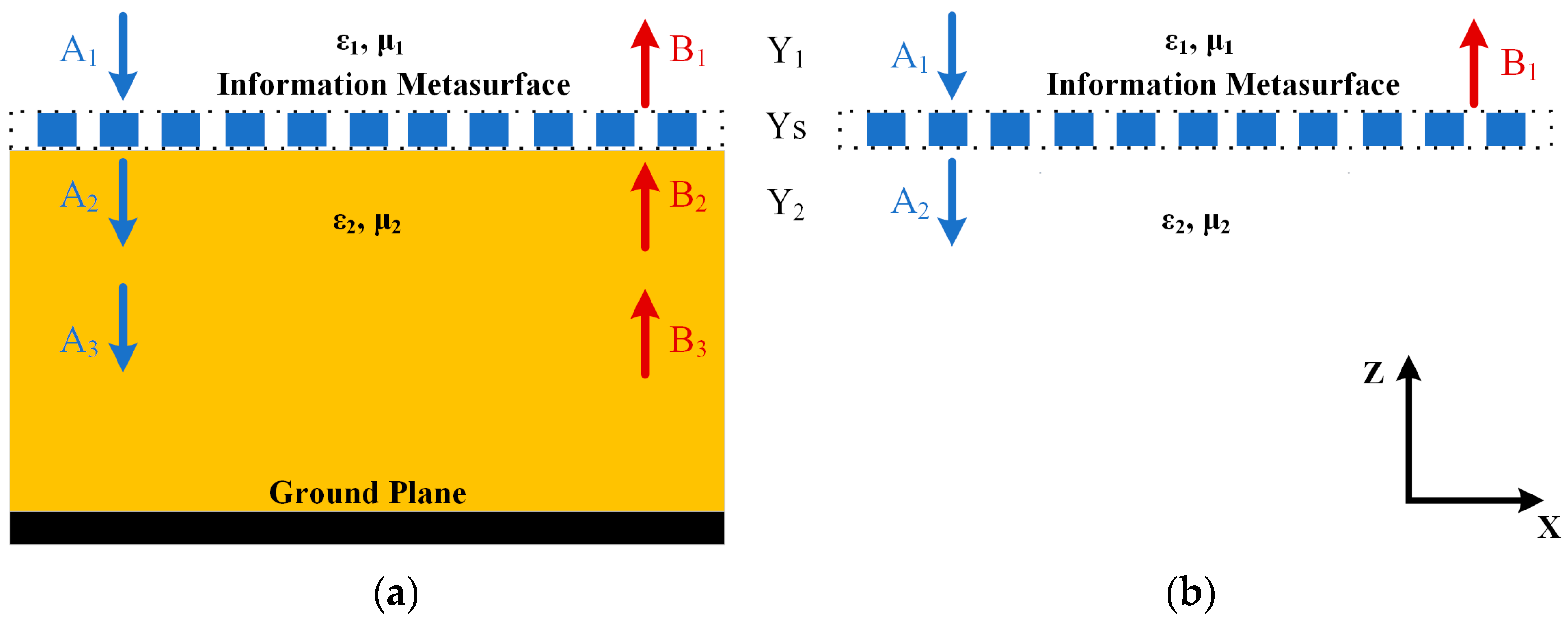
In the scenario illustrated in Figure 2a concerning a reflective information metasurface, it is hypothesized that the admittances (inverse of impedances) for the incident space, metasurface layer, and intermediary medium layer are designated as Y1, YS, and Y2, respectively, where and . The EM wave incident in the negative direction along the Z-axis passes through the metasurface and the medium layer before being reflected by the ground metal plane. Meanwhile, EM waves propagating in both forward and backward directions coexist within the incident space and the medium layer.
The electric field amplitudes of EM waves propagating in the forward and backward directions within each layer are denoted by Ai and Bi, respectively. At the interface of the metasurface, the boundary conditions of Maxwell’s equations can be applied to obtain:
When EM waves propagate through the dielectric layer, they satisfy the following equation:
where, k represents the propagation constant in the dielectric layer. Therefore, the transmission matrix of the entire structure is described as follows:
Assuming that EM waves are fully reflected by the ground metal plane, the reflection coefficient is −1, that is, A3 = −B3. Substituting into Equation (6), the expression for the reflection coefficient can be obtained as follows:
Similarly, for the single-layer transmissive information metasurface shown in Figure 2b, it can be concluded that:
For a more comprehensive discussion, please refer to the principles of equivalent circuit theory and the methodology of S-parameter inversion as delineated in reference [27].
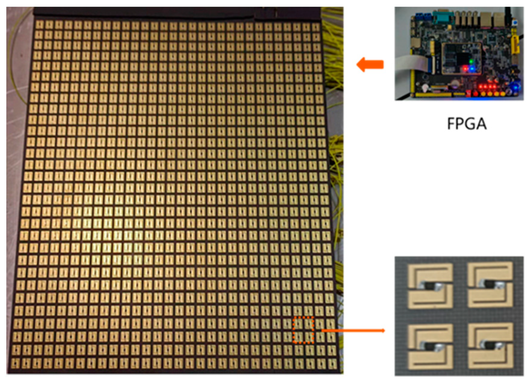
Building upon the theoretical foundation of information metasurface, the construction and subsequent testing of a prototype system designed for broadband target jamming in SAR applications, incorporating a matrix of 900 units (arranged in a 30 × 30 configuration), have been undertaken in this section. The output voltage from a Field-Programmable Gate Array (FPGA) is utilized to control the state (either ‘on’ or ‘off’) of each unit within the metasurface array. This mechanism allows for the modulation of the overall EM scattering state of the information metasurface, as depicted in Figure 3.
Information Metasurfaces are functional materials capable of altering the scattering properties of incident EM waves. The CBC of a metasurface is defined as
where A is the amplitude coefficient and φ is the phase coefficient. In this study, we disregard the amplitude coefficient A and set it to a constant value of 1. Due to current hardware limitations, precise phase modulation of metasurfaces is challenging; hence, we employ bit numbers to represent the discrete number of phase states that metasurfaces can achieve. In our research, we set the discrete phase states for 1-bit modulation to typical values of [0, π]. Assuming a 1-bit phase modulation for the metasurface, it adds the corresponding relative phase π to the incident EM wave in each time slice of width Tc in the original signal. Thus, the modulation function of the information metasurface on the incident EM wave can be expressed as
where Ri is the CBC of the metasurface in the i-th time slice, and g(·) is the rectangular gate function with a width of Tc. Consequently, the echoed signal modulated by the metasurface can be represented as
s(t) represents the unmodulated radar echo signal.
The experimental outcomes regarding the reflection amplitude and phase for diverse encoding sequences of the prototype are delineated in Table 1. The variation in the amplitude of the reflected wave is confined within a range of 12.85 dB, while the reflection phase exhibits a linear progression from 0 to 125°, evidencing a robust linear correlation. These findings underscore the capability of the information metasurface in the high-precision manipulation of EM scattering characteristics.
The actual gain in 9.6 GHz at 0° and 30° beam directions is shown in Figure 4, with tests conducted using a horizontally polarized linear feed source. The phase distributions for 0° beam direction, 30° beam direction, and random diffuse reflection are presented in Figure 5, where different colors represent the phase of each unit on the metasurface. It is noteworthy that the information metasurface with a random diffuse reflection state has a lower amplitude of CBC compared with those for beam directions of 0° and 30°. The metasurface array exhibits good beam scanning characteristics, with the maximum tunable gain around 9.6 GHz reaching up to 21.7 dB at 0°. The gain for the E-plane and H-plane at 30° is on average 3 dB lower than at 0° within the 9.3–10 GHz range. The sidelobe level (SSL) is less than −12.9 dB at 0° and less than −10 dB at 30°.
In this work, precise modulation of the digital state for metasurface units is achieved by embedding radio frequency switches within the unit structure, utilizing the switching between “ON” (conductive) and “OFF” (non-conductive) states of PIN diodes. Furthermore, by employing FPGA technology for the metasurface, this research innovatively integrates the jamming digital encoding array with the EM physical characteristics of the information metasurface, facilitating intelligent control over the metasurface’s jamming effects. When the jamming system installed on critical targets is activated as the satellite-borne SAR beam covers the target, it can flexibly and effectively modulate parameters such as phase, amplitude, and polarization of the target’s SAR echo, introducing abrupt and rapid perturbations into the typical phase distribution of reflected LFM signals. This modulation impedes the SAR sensor’s ability to accurately reconstruct the target’s image, thereby enabling effective jamming and protection of the target, as illustrated in Figure 6.
3. Target Jamming System Signal Model and Modulation Method
3.1. The Model of the SAR Echo Signal
The echo signal for a point target, characterized by CBC denoted as , is described as follows:
where τ and η are the range and azimuth time, respectively, and wr and wa correspond to the respective profiles. The carrier frequency is denoted by f0, c represents the speed of light, R(η) indicates the slant range, and Kr refers to the chirp slope. If the CBC σ0 of a point target undergoes rapid changes with a frequency of 1/Tp, the expression for the range signal with a pulse duration of Tr can be given as follows:
The quantity of changes, denoted as N, is equivalent to the quotient obtained by dividing the pulse duration Tr by the period Tp. Consequently, the expression for the range signal may be articulated as follows:
where and represent the specific amplitude and phase of CBC within the short temporal duration Tp. Subsequently, a Fast Fourier Transform is employed, culminating in the derivation of the expression within the frequency domain:
where Bp symbolizes the product of Tp and Kr, and H(f) signifies the Fourier transform of the quadratic phase term. It is noteworthy that the time-bandwidth product is adequately minimal, thereby rendering the stationary phase principle non-applicable under these conditions [28]. Customarily, matched filtering is utilized in SAR sensors to attenuate the effects of the quadratic phase term. As a result, the residual terms subsequent to this processing step are delineated as follows:
Subsequently, the Inverse Fast Fourier Transform is applied to transform the frequency-domain representation back into the time-domain signal for the purpose of pulse compression.
Within the short temporal duration, the waveform and phase are modified by and , respectively, introducing an interference effect on the imaging results that corresponds to distinct variations in the CBC. Considering the symmetry between range and azimuth signals, and the significantly higher range sampling frequency fs in comparison to the pulse repetition frequency, a parallel influence is exerted on the azimuth signal. This culminates in analogous outcomes within the two-dimensional image domain in turn.
3.2. The Simulation of a Point Target
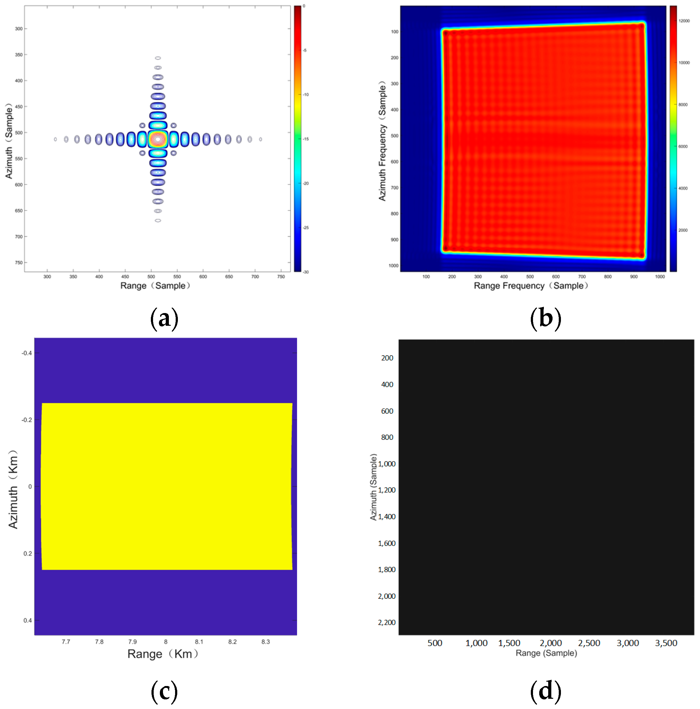
To demonstrate the effectiveness of the proposed jamming method, a spaceborne SAR simulation experiment involving nine point targets is conducted. Notably, to correspond with the experiments in the next section based on the SAR-Aircraft-1.0 dataset of the Gaofen-3 satellite, the satellite orbit and radar system parameters of the spaceborne SAR are set to match those of the Gaofen-3 satellite, as listed in Table 2 and Table 3 [29]. The SAR system operates in a staring spotlight mode and assumes no squint angle. The scene center resolution is 0.55 m × 0.59 m (slant range × azimuth). The geometry of the simulated scene is shown in Figure 7, including the distribution of targets on the surface of the earth and the slant range plane after deramping.
The simulation for the point target P5 serves to validate the phase modification of the information metasurface, as depicted in Figure 8. It is discernible that microsecond-level variations in the CBC for the information metasurface induce defocusing of the SAR image in both the azimuth and range directions, corroborating the prior analysis of SAR echo signals. Figure 8b, c illustrate the amplitude of the SAR echo and its two-dimensional spectrum. Notably, in contrast to those of an echo from point target P5 not modulated, as shown in Figure 9, the information metasurface is capable of rapidly and precisely adjusting the phase of its reflected EM waves without altering the amplitude of the CBC. This adjustment follows the jamming digital encoding array in Figure 8d, thereby achieving the intended jamming effect while maintaining the CBC’s amplitude unchanged.
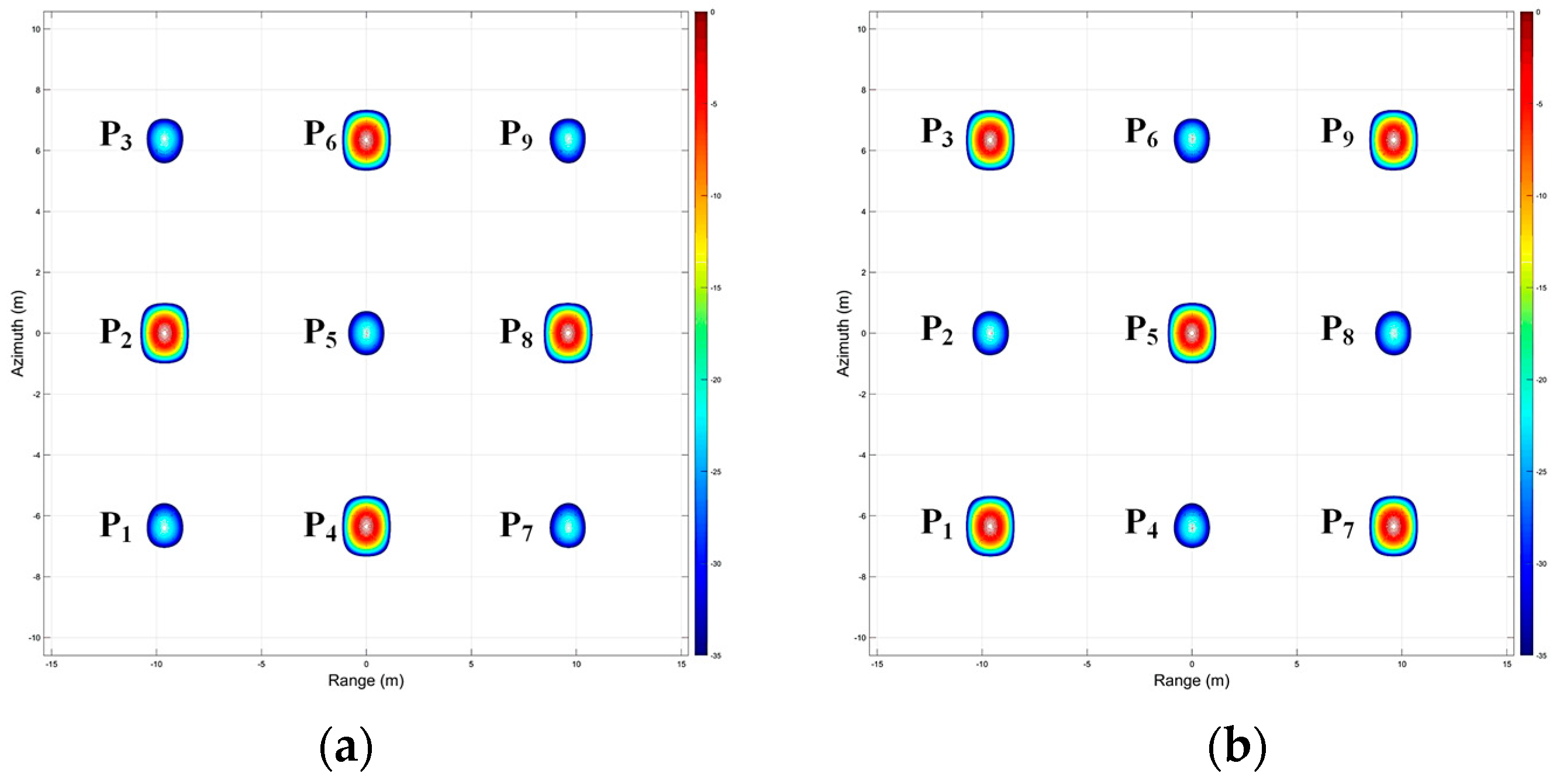
The simulation results for a 3 × 3 array of point targets, each integrated with information metasurfaces (ranging from point P1 to P9), are primarily employed to validate the efficacy of multi-mode jamming protections. These protections, inclusive of EM deception and the generation of multiple false targets, are explicitly designed to safeguard critical targets. As illustrated in Figure 10, by modulating the CBC of different information metasurfaces, such as P1 and P6, the amplitude and phase of the corresponding SAR image can be artificially manipulated. This manipulation facilitates the transformation of the SAR image of point P3 into that of point P6, with distinct contours representing different CBCs, thereby accomplishing the objective of EM deception. Specifically, the amplitude of CBC for point P1 escalates from −14.16 dB (mode I, Figure 10a) to −3.31 dB (mode II, Figure 10b), whereas point P6 exhibits a diametrically opposite trajectory.
Furthermore, the introduction of a finite Dirac comb function to modify the CBC phase of point P3 effectively generates multiple false targets, as clearly visible within the blue region depicted in Figure 11. Notably, when the CBC phase of P3 is adjusted by a time-limited impulse train with an amplitude of 0.75π, two false images of P3 emerge within the region demarcated by blue dashed lines, forming around it along the azimuth direction. The underlying reason for this phenomenon is the multiplication of the finite Dirac comb function with the echo signal in the frequency spectrum, which is equivalent to the convolution of their inverse fast Fourier transforms in the time domain. This operation shifts the energy of the echo signal to incorrect positions, thereby resulting in the emergence of multiple spurious images. Therefore, the utilization of a finite Dirac comb function with varying periods and amplitudes can produce false targets at different locations and in varying quantities within the SAR image domain. The flexibility of this method offers new possibilities for electronic countermeasure strategies, allowing for the adjustment of jamming tactics based on specific scenarios to meet diverse tactical requirements. It is particularly noteworthy that, in comparison to the SAR image profile of point P6, the profiles of the false targets P3′ and P3″ exhibit certain inaccuracies, with the main lobe showing slight deformation and the side lobes displaying irregular amalgamations. This occurrence is primarily due to the incomplete segmentation of the signal spectrum, which affects the correct reconstruction of the frequency components of the echo signal, thereby producing distorted false targets in the SAR image. This finding underscores the importance of precision in signal processing during jamming operations, especially when designing complex jamming patterns using information metasurface, necessitating meticulous control over the spectral processing of the jamming digital encoding array to ensure the accuracy and effectiveness of the jamming effects.
4. Verification of the Target Jamming System
4.1. Verification Based on Spacebrone SAR Data
In this section, we conduct a comprehensive evaluation, analysis, and discussion on the implementation of adjustable EM deception and the generation of multiple false targets for the ARJ-21 aircraft (length 33.46 m, wingspan 27.28 m) located within the Beijing Capital International Airport area. The Gaofen-3 satellite’s SAR-Aircraft-1.0 dataset is employed, utilizing a single polarization imaging mode and spotlight imaging technique, with the satellite orbit and radar system parameters consistent with those described in Table 2 and Table 3 [29]. As depicted in Figure 12, the ARJ-21 aircraft target positioned above the right side of the airport terminal is presented in the SAR image with a clear resolution of approximately 1 m. Through the use of intelligent SAR target detection and recognition algorithms, the aircraft’s model, type, location, and status information can be effectively confirmed, enabling its differentiation from other types of aircraft within the airport region. Leveraging high-precision SAR imaging technology, in conjunction with advanced image processing and analysis algorithms, specific features of the ARJ-21 in Figure 12b, such as the wings, tail, and fuselage contours, are distinctly identifiable. This provides robust technical support for airport security management and aircraft monitoring.
However, as depicted in Figure 13a, by analyzing the CBC of the surrounding environment, when the information metasurface jamming system prototype is activated on the ARJ-21 aircraft, the target’s image is rapidly modulated to align with the surrounding environment. The specific features of the target are effectively concealed, in alignment with the aforementioned theoretical predictions, thereby achieving adjustable EM deception based on the information of the surrounding environment. Furthermore, when the phase is adjusted using the finite Dirac comb function method proposed above on the jamming system prototype deployed on the ARJ-21 aircraft, two false targets can be generated as needed to confuse potential threats or surveillance systems. These false targets not only visually simulate the basic characteristics of the ARJ-21 aircraft in the SAR image but also reflect similar EM characteristics in intelligent SAR target detection and recognition, thereby enhancing the survivability and stealth of the target in complex environments. The corresponding imaging results are displayed in Figure 13b. However, it is important to emphasize that the false images of the target appear somewhat illusory and indistinct within the region demarcated by blue dashed lines. This limitation may arise from the incomplete matching of filters in pulse compression due to the division of the frequency spectrum. This aspect will be further investigated and refined in subsequent research efforts. It is worth mentioning that by finely adjusting the parameters of the information metasurface jamming system prototype, such as phase, amplitude, and frequency, it is possible to customize the quantity, spatial distribution, and characteristics of the false targets in alignment with specific threat scenarios. This approach significantly enhances the realism and credibility of the SAR jamming deception effect.
4.2. Verification for the Flight Experiment
To validate the efficacy of the information metasurface jamming system prototype in real-life situations, airborne SAR flight experiments were conducted. The SAR system utilized for the flight experiments is depicted in Figure 14a, employing state-of-the-art phased array antennas and digital beamforming technology, with the corresponding radar parameters listed in Table 4. Figure 14b displays the proposed jamming system prototype, measuring 1800 cm2 and comprising 900 metasurface units. By employing FPGA technology, the digital encoding array was integrated into the jamming system prototype, facilitating real-time intelligent control over the metasurface’s EM characteristics.
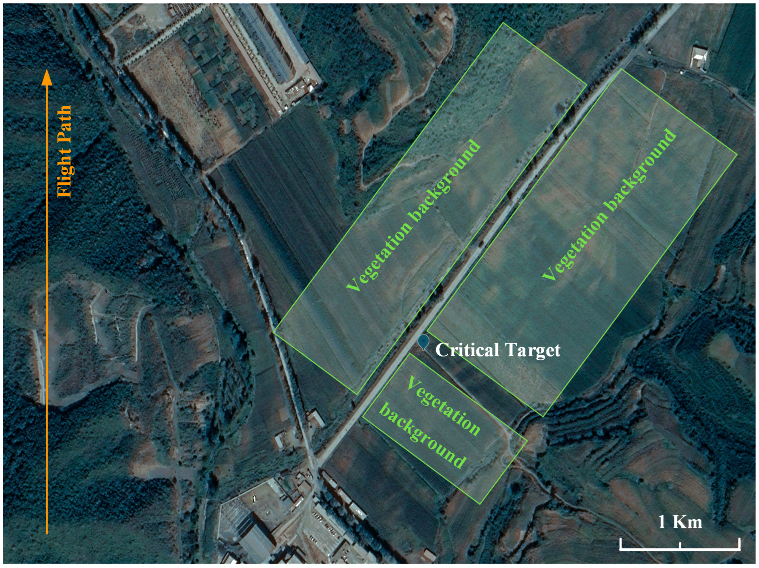
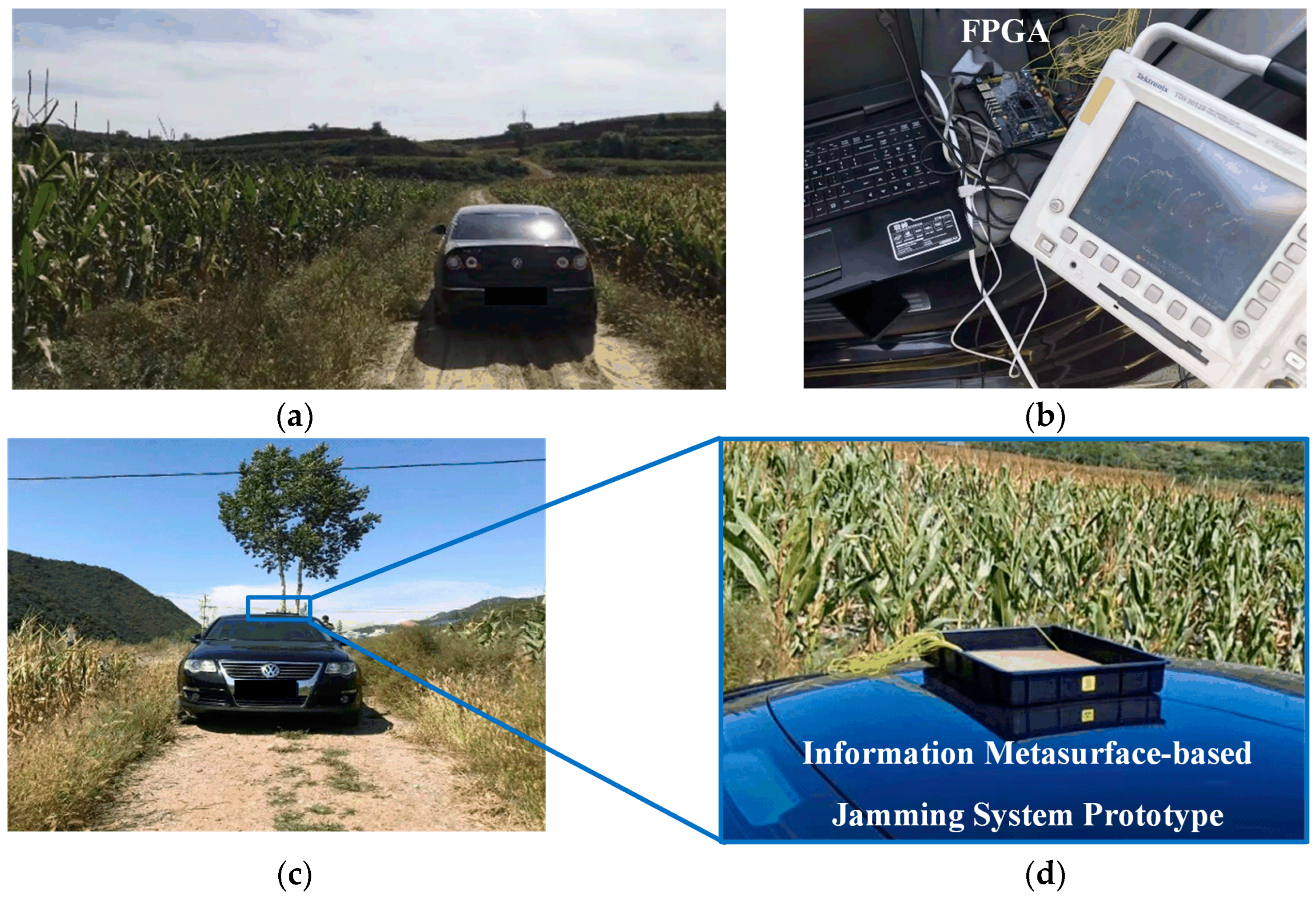
This experiment was conducted in the northern valley of Miyun Airport in Beijing, China, utilizing an airborne SAR platform operating in spotlight mode to achieve a ground-distance resolution of 0.15 m. Additionally, to assess the performance of the jamming system prototype, the experiment was specifically designed with a series of flight paths to ensure comprehensive detection of the target from various angles and distances for a thorough analysis of the jamming effects. The flight experiment layout, including the precise location of the critical target, is detailed in Figure 15, where the aircraft’s flight altitude was set at 3000 m, targeting the ground with a 50° down-looking angle. As can be seen from Figure 16, the protected target selected for this experiment was a black Volkswagen sedan characterized by a steel shell with dimensions of 4.95 m in length, 1.84 m in width, and 1.45 m in height, parked beside a roadway and surrounded by low-lying vegetation with an average height of 1 to 1.8 m. Under these experimental conditions, the information metasurface jamming system prototype was installed on the top of the vehicle, designed to effectively reflect SAR echoes. During the experiment, the digital encoding array was dynamically integrated into the information metasurface in real-time via FPGA, allowing flexible adaptation to different usage scenarios and corresponding adjustments to achieve optimal jamming effects. Notably, this information metasurface jamming system prototype comprises 900 units and operates at a total power of merely 9.43 watts, indicating its efficiency in generating effective jamming outcomes while maintaining a low energy consumption level.
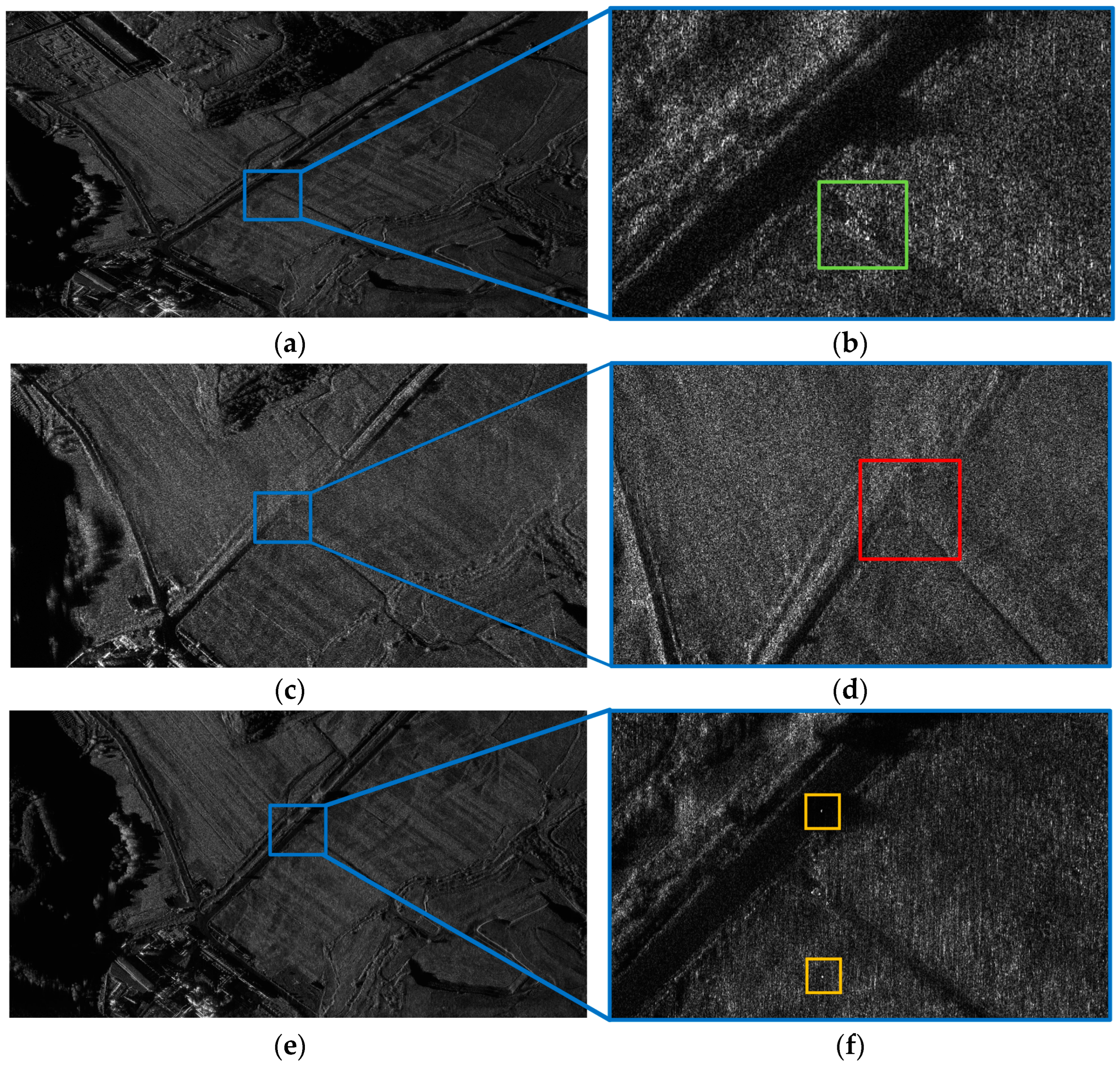
The flight results are presented in Figure 17. A discernible comparison of the target’s jamming effect in the different operational modes of the jamming system is observed. When the information metasurface-based jamming system prototype remains deactivated, the EM scattering characteristics of the critical target vehicle are clearly identifiable in the SAR image (as shown in Figure 17b), marked by a green square. This feature does not match the SAR characteristics of the surrounding vegetation, making the target easily identifiable by intelligent SAR target detection and recognition algorithms. Conversely, when the information metasurface-based jamming system prototype is activated, the EM scattering characteristics of the critical target vehicle become blurred in the SAR image (as shown in Figure 17d), marked by a red square, blending seamlessly with the SAR characteristics of the surrounding vegetation, effectively reducing the accuracy of intelligent SAR target detection and recognition algorithms. The similarity between the SAR imaging features of the protected target and the surrounding vegetation background is 87.2%, thereby achieving effective EM deception. When the digital encoding array based on the finite Dirac comb function method is integrated into the jamming system prototype (with the variation frequency set at 1250 KHz), it is distinctly observable in the SAR image (as depicted in Figure 17e) that two false targets of information metasurface, as indicated by amber squares. If the information metasurface covers the entire body of the vehicle, it becomes clearly observable that two false targets, resembling the critical target vehicle, emerge. These differ significantly from the SAR characteristics of the surrounding vegetation, effectively confusing intelligent SAR target detection and recognition algorithms.
By employing techniques such as field experiment data collection and large-scale EM simulations, we are able to acquire CBC for scenes in various terrain environments. By rapidly adjusting the CBC of the information metasurface within the jamming system, it can swiftly adapt to electromagnetic camouflage in diverse types of scenarios, thereby safeguarding critical targets.
5. Discussion
With the assistance of information metasurfaces, the SAR target jamming system can integrate intelligent information processing algorithms with space-time-coding digital metasurface units, adeptly modulating the SAR’s reflected echoes. This allows for effective disruption of intelligent SAR target detection and recognition algorithms, for instance, through the generation of false targets, signal spoofing, and EM deception. Furthermore, the proposed jamming system fundamentally leverages the target’s inherent spatio-temporal changeable CBC, unlike other SAR jamming systems that require extensive a priori system parameters. This approach is effective for any type of airborne/spaceborne SAR system. From the perspective of SAR signal processing, this spatio-temporal changeable CBC effectively introduces a modulatable amplitude and phase component into the echo signals, thereby altering the SAR image of the protected target significantly. It is noteworthy that through precise adjustments to the dimensions of the metasurface units, the system demonstrates an exceptional capability for EM scattering modulation across a wide frequency range, from the P to the Ka band, covering the operational frequency spectrum of prevalent spaceborne and airborne SAR systems.
In subsequent research, it is aimed to be expanded upon more intelligent information processing algorithms, thereby enabling the deployment of a broader array of protective measures for critical false targets. Exploration of the conformal design of the jamming system, in conjunction with the EM scattering characteristics of the protected targets, to generate more realistic decoys will also be conducted. Moreover, an extension of this concept, based on information metasurfaces, to the infrared and visible spectra, is planned, aiming to achieve jamming protection against other types of radar systems.
6. Conclusions
In summary, we have introduced a broadband SAR target jamming system utilizing an information metasurface, controlled via a FPGA, and presented a prototype system as an illustrative example. Simulation results, based on the SAR-Aircraft-1.0 dataset from the Gaofen-3 satellite and flight experiment results with an airborne SAR, have elucidated effective protection measures, including adjustable EM deception and the generation of multiple false targets. However, certain limitations, such as the emergence of fuzzy false target images, necessitate further investigation and resolution. Future research will concentrate on refining the target jamming system, expanding the array of protective measures against critical targets, and conducting tests in collaboration with more complex spaceborne SAR systems. Moreover, we plan to extend this concept based on information metasurfaces to the infrared and visible light spectra, aiming to achieve comprehensive radar jamming protection.
Author Contributions
Conceptualization, H.L., Z.L. and K.L.; methodology, H.L. and Z.L.; validation, H.L., Z.L., K.X., C.L. and Y.L.; formal analysis, H.L. and Z.L; writing—original draft preparation, H.L. and Z.L.; writing—review and editing, K.L. and Y.D.; supervision, K.L. and Y.D.; funding acquisition, K.L. All authors have read and agreed to the published version of the manuscript.
Funding
Aerospace Information Research Institute: E1H31603.
Data Availability Statement
The raw data supporting the conclusions of this article will be made available by the authors on request.
Acknowledgments
The author would like to thank S. Ren, Y. Wen, and C. Chen for their tremendous help and technical discussions.
Conflicts of Interest
The authors declare no conflicts of interest.
References
- Fu, K.; Fu, J.; Wang, Z.; Sun, X. Scattering-Keypoint-Guided Network for Oriented Ship Detection in High-Resolution and Large-Scale SAR Images. IEEE J. Sel. Top. Appl. Earth Observ. Remote Sens. 2021, 14, 11162–11178. [Google Scholar] [CrossRef]
- Liu, B.; Zhang, Z.; Liu, X.; Yu, W. Representation and spatially adaptive segmentation for PolSAR images based on Wedgelet analysis. IEEE Trans. Geosci. Remote Sens. 2015, 53, 4797–4809. [Google Scholar] [CrossRef]
- Zhang, M.; Li, W.; Tao, R.; Wang, S. Transfer learning for optical and SAR data correspondence identification with limited training labels. IEEE J. Sel. Topics Appl. Earth Observ. Remote Sens. 2020, 14, 1545–1557. [Google Scholar] [CrossRef]
- Guo, Q.; Wang, H.; Xu, F. Scattering Enhanced Attention Pyramid Network for Aircraft Detection in SAR Images. IEEE Trans. Geosci. Remote Sens. 2021, 59, 7570–7587. [Google Scholar] [CrossRef]
- Yang, G.; Li, H.; Yang, W.; Fu, K.; Sun, Y.; Emery, W.J. Unsupervised change detection of SAR images based on variational multivariate Gaussian mixture model and Shannon entropy. IEEE Geosci. Remote Sens. Lett. 2019, 16, 826–830. [Google Scholar] [CrossRef]
- Du, L.; Dai, H.; Wang, Y.; Xie, W.; Wang, Z. Target Discrimination Based on Weakly Supervised Learning for High-Resolution SAR Images in Complex Scenes. IEEE Trans. Geosci. Remote Sens. 2020, 58, 461–472. [Google Scholar] [CrossRef]
- Du, L.; Li, L.; Wei, D.; Mao, J. Saliency-guided single shot multibox detector for target detection in SAR images. IEEE Trans. Geosci. Remote Sens. 2020, 58, 3366–3376. [Google Scholar] [CrossRef]
- Shahzad, M.; Maurer, M.; Fraundorfer, F.; Wang, Y.; Zhu, X.X. Buildings detection in VHR SAR images using fully convolution neural networks. IEEE Trans. Geosci. Remote Sens. 2019, 57, 1100–1116. [Google Scholar] [CrossRef]
- Goj, W.W.; Goi, W.W. Synthetic-Aperture Radar and Electronic Warfare, 2nd ed.; Artech House: Norwood, MA, USA, 1989. [Google Scholar]
- Spezio, A.E. Electronic warfare systems. IEEE Trans. Microw. Theory 2002, 50, 633–644. [Google Scholar] [CrossRef]
- Poisel, R. Information Warfare and Electronic Warfare Systems, 3rd ed.; Artech House: London, UK, 2013. [Google Scholar]
- Farina, A. Electronic counter-countermeasures. In Radar Handbook, 2nd ed.; McGraw-Hill: New York, NY, USA, 2008. [Google Scholar]
- Pendry, J.B.; Schurig, D.; Smith, D.R. Controlling electromagnetic fields. Science 2006, 312, 1780–1782. [Google Scholar] [CrossRef]
- Engheta, N.; Ziolkowski, R.W. Metamaterials: Physics and Engineering Explorations; Wiley: New York, NY, USA, 2006. [Google Scholar]
- Schurig, D.; Mock, J.J.; Justice, B.J.; Cummer, S.A.; Pendry, J.B.; Starr, A.F.; Smith, D.R. Metamaterial electromagnetic cloak at microwave frequencies. Science 2006, 314, 977–980. [Google Scholar] [CrossRef] [PubMed]
- Wang, H.; Huang, J.; Wang, H.; Li, Y.; Sui, S.; Li, W.; Chen, C.; Zhang, J.; Qu, S. Chaos-based coding metasurface for radar cross-section reduction. J. Phys. D Appl. Phys. 2019, 52, 405304. [Google Scholar] [CrossRef]
- Wang, C.; Wang, R.; An, Z.; Liu, L.; Zhou, Y.; Tang, Z.; Wang, W.; Zhang, S. A low-cost digital coding metasurface applying modified ‘crusades-like’ cell topologies for broadband RCS reduction. J. Phys. D Appl. Phys. 2022, 55, 485001. [Google Scholar] [CrossRef]
- Rahman, S.U.; Cao, Q.; Akram, M.R.; Amin, F.; Wang, Y. Multifunctional polarization converting metasurface and its application to reduce the radar cross-section of an isolated MIMO antenna. J. Phys. D Appl. Phys. 2020, 53, 305001. [Google Scholar] [CrossRef]
- Ghosh, S.; Srivastava, K.V. Polarization-insensitive dual-band switchable absorber with independent switching. IEEE Antennas Wireless Propag. Lett. 2017, 16, 1687–1690. [Google Scholar] [CrossRef]
- Ghosh, S.; Srivastava, K.V. Polarization-insensitive single- and broadband switchable absorber/reflector and its realization using a novel biasing technique. IEEE Trans. Antennas Propag. 2016, 64, 3665–3670. [Google Scholar] [CrossRef]
- Kong, P.; Yu, X.; Zhao, M.; He, Y.; Miao, L.; Jiang, J. Switchable frequency selective surfaces absorber/reflector for wideband applications. J. Electromagn. Waves Appl. 2015, 29, 1473–1485. [Google Scholar] [CrossRef]
- Ghosh, S.; Srivastava, K.V. Polarisation-independent switchable absorber/reflector. Electron. Lett. 2016, 52, 1141–1143. [Google Scholar] [CrossRef]
- Qian, C.; Zheng, B.; Shen, Y.; Jing, L.; Li, E.; Shen, L.; Chen, H. Deep-learning-enabled self-adaptive microwave cloak without human intervention. Nat. Photonics 2020, 14, 383–390. [Google Scholar] [CrossRef]
- Wang, J.; Feng, D.; Zhang, R.; Xu, L.; Hu, W. An Inverse Synthetic Aperture Radar Image Modulation Method Based on Coding Phase-Switched Screen. IEEE Sens. J. 2019, 19, 7915–7922. [Google Scholar] [CrossRef]
- Wang, J.; Feng, D.; Xu, Z.; Wu, Q.; Hu, W. Time-Domain Digital-Coding Active Frequency Selective Surface Absorber/Reflector and Its Imaging Characteristics. IEEE Trans. Antennas Propag. 2021, 69, 3322–3331. [Google Scholar] [CrossRef]
- Liu, S.; Cui, T. Concepts, Working Principles, and Applications of Coding and Programmable Metamaterials. Adv. Opt. Mater. 2017, 5, 1700624. [Google Scholar] [CrossRef]
- Yu, N.; Genevet, P.; Kats, M.A.; Aieta, F.; Tetienne, J.P.; Capasso, F.; Gaburro, Z. Light propagation with phase discontinuities: Generalized laws of reflection and refraction. Science 2011, 334, 333–337. [Google Scholar] [CrossRef]
- Cumming, I.; Wong, F. Digital Signal Processing of Synthetic Aperture Radar Data: Algorithms and Implementations, 3rd ed.; Artech House: Norwood, MA, USA, 2004. [Google Scholar]
- Wang, Z.; Kang, Y.; Zeng, X.; Wang, Y.; Zhang, T.; Sun, X. SAR-Aircraft-1.0: High-resolution SAR aircraft detection and recognition dataset. J. Radars. 2023, 12, 906–922. [Google Scholar]
Figure 1.
The proposed target jamming system based on information metasurface.

Figure 2.
Information metasurface transmission matrix model. (a) Reflective metasurface transmission matrix model. (b) Transmissive metasurface transmission matrix model.
Figure 2.
Information metasurface transmission matrix model. (a) Reflective metasurface transmission matrix model. (b) Transmissive metasurface transmission matrix model.

Figure 3.
The proposed 30 × 30 unit prototype system controlled by FPGA.

Figure 4.
The actual gain in 9.6 GHz at 0° and 30° beam directions.

Figure 5.
The phase distributions for different beam directions. (a,b) 0° beam direction. (c,d) 30° beam direction. (e) Random diffuse reflection.
Figure 5.
The phase distributions for different beam directions. (a,b) 0° beam direction. (c,d) 30° beam direction. (e) Random diffuse reflection.

Figure 6.
The diagram of the proposed target jamming system for SAR.

Figure 7.
The distribution of targets for simulation. (a) Distribution of targets on the surface of earth. (b) Distribution of targets in slant range plane after deramping.
Figure 7.
The distribution of targets for simulation. (a) Distribution of targets on the surface of earth. (b) Distribution of targets in slant range plane after deramping.

Figure 8.
The simulation for the modification of phase. (a) Imaging results. (b) Two-dimensional spectrum of the SAR echo. (c) Amplitude of the SAR echo. (d) Jamming the digital encoding array.
Figure 8.
The simulation for the modification of phase. (a) Imaging results. (b) Two-dimensional spectrum of the SAR echo. (c) Amplitude of the SAR echo. (d) Jamming the digital encoding array.

Figure 9.
The simulation for a point target is not modulated. (a) Imaging results. (b) Two-dimensional spectrum of the SAR echo. (c) Amplitude of the SAR echo. (d) Zero digital encoding array.
Figure 9.
The simulation for a point target is not modulated. (a) Imaging results. (b) Two-dimensional spectrum of the SAR echo. (c) Amplitude of the SAR echo. (d) Zero digital encoding array.

Figure 10.
The point simulation results of EM deception. (a) EM deception mode I. (b) EM deception mode II.
Figure 10.
The point simulation results of EM deception. (a) EM deception mode I. (b) EM deception mode II.

Figure 11.
The point simulation results of multiple false targets.

Figure 12.
The spotlight SAR image of the ARJ-21 aircraft located within the airport area. (a) Overview of the image. (b) Close insight into a zoomed-in area.
Figure 12.
The spotlight SAR image of the ARJ-21 aircraft located within the airport area. (a) Overview of the image. (b) Close insight into a zoomed-in area.

Figure 13.
The SAR deception results of the information metasurface jamming system prototype. (a) EM deception. (b) Multiple false targets.
Figure 13.
The SAR deception results of the information metasurface jamming system prototype. (a) EM deception. (b) Multiple false targets.

Figure 14.
The hardware system of the experiment. (a) Phased array antennas outside the cabin. (b) the information metasurface jamming system prototype.
Figure 14.
The hardware system of the experiment. (a) Phased array antennas outside the cabin. (b) the information metasurface jamming system prototype.

Figure 15.
The airborne geometry, including the critical target location.

Figure 16.
The geometry and configuration of the proposed jamming system prototype. (a) Environment of ground testing. (b) System prototype under test. (c) Layout of the information metasurface prototype. (d) Close insight into a zoomed-in area.
Figure 16.
The geometry and configuration of the proposed jamming system prototype. (a) Environment of ground testing. (b) System prototype under test. (c) Layout of the information metasurface prototype. (d) Close insight into a zoomed-in area.

Figure 17.
The experimental flight results. (a) Deactivated jamming system prototype. (b) Close insight into a zoomed-in area of (a). (c) EM deception mode. (d) Close insight into a zoomed-in area of (c). (e) Multiple false targets mode. (f) Close insight into a zoomed-in area of (e).
Figure 17.
The experimental flight results. (a) Deactivated jamming system prototype. (b) Close insight into a zoomed-in area of (a). (c) EM deception mode. (d) Close insight into a zoomed-in area of (c). (e) Multiple false targets mode. (f) Close insight into a zoomed-in area of (e).


Table 1.
The reflection amplitude and phase.
| Encoding Sequence | Amplitude (dB) | Phase (°) |
|---|---|---|
| 1111111…1111111 | 6.25 | 125 |
| 0101010…0101010 | 3.94 | 63 |
| … | … | … |
| 0111011…0111110 | 12.85 | 79 |
| 0000000…0000000 | 0 | 0 |
Table 2.
Parameters of the Gaofen-3 satellite orbit.
| Parameters | Value |
|---|---|
| Eccentricity | 0.0015 |
| Ascending node | 0° |
| Inclination | 98.4° |
| Semi-major axis | 7126.4 km |
| Argument of perigee | 270° |
Table 3.
Simulated spaceborne SAR staring spotlight acquisition.
| Parameters | Value |
|---|---|
| Wavelength | 5.35 cm |
| Transmission bandwidth | 240 MHz |
| Sampling rate | 300 MHz |
| Slant range | 7126.4 km |
| Incidence angle | 42° |
| Antenna azimuth beam width | 0.45° |
| Coherent integration angle | 1.5° |
| Squint angle at aperture center | 0° |
| Nominal doppler centroid | 16.857 KHz |
| PRF | 5.364 KHz |
| Scene center resolution | 0.55 m × 0.59 m |
Table 4.
Parameters of airborne radar system.
| Parameters | Value |
|---|---|
| Wavelength | 3.13 cm |
| Transmission bandwidth | 1200 MHz |
| Sampling rate | 1500 MHz |
| Sub-antenna length | 0.3 m |
| Incidence angle | 50° |
| Squint angle at aperture center | 0° |
| Equivalent velocity | 180 m/s |
| PRF | 2 KHz |
| Platform height | 3 km |
| Azimuth and range swath (ground range) | 8 km × 5 km |
Disclaimer/Publisher’s Note: The statements, opinions and data contained in all publications are solely those of the individual author(s) and contributor(s) and not of MDPI and/or the editor(s). MDPI and/or the editor(s) disclaim responsibility for any injury to people or property resulting from any ideas, methods, instructions or products referred to in the content. |
© 2024 by the authors. Licensee MDPI, Basel, Switzerland. This article is an open access article distributed under the terms and conditions of the Creative Commons Attribution (CC BY) license (https://creativecommons.org/licenses/by/4.0/).
Share and Cite
MDPI and ACS Style
Li, H.; Li, Z.; Liu, K.; Xu, K.; Luo, C.; Lv, Y.; Deng, Y. A Broadband Information Metasurface-Assisted Target Jamming System for Synthetic Aperture Radar. Remote Sens. 2024, 16, 1499. https://doi.org/10.3390/rs16091499
AMA Style
Li H, Li Z, Liu K, Xu K, Luo C, Lv Y, Deng Y. A Broadband Information Metasurface-Assisted Target Jamming System for Synthetic Aperture Radar. Remote Sensing. 2024; 16(9):1499. https://doi.org/10.3390/rs16091499
Chicago/Turabian StyleLi, Hua, Zhenning Li, Kaiyu Liu, Kaijiang Xu, Chao Luo, You Lv, and Yunkai Deng. 2024. "A Broadband Information Metasurface-Assisted Target Jamming System for Synthetic Aperture Radar" Remote Sensing 16, no. 9: 1499. https://doi.org/10.3390/rs16091499
Note that from the first issue of 2016, this journal uses article numbers instead of page numbers. See further details here.