Article

Development of a Mid-Infrared Sea and Lake Ice Index (MISI) Using the GOES Imager

1
Department of Civil and Environmental Engineering, Rowan University, Glassboro, NJ 08028, USA
2
NOAA Cooperative Remote Sensing Science and Technology Center (CREST), City University of New York, New York, NY 10031, USA
3
National Oceanic and Atmospheric Administration (NOAA), 1225 West Dayton St., Madison, WI 53706, USA
*
Author to whom correspondence should be addressed.
Remote Sens. 2016, 8(12), 1015; https://doi.org/10.3390/rs8121015
Submission received: 8 September 2016 / Revised: 3 November 2016 / Accepted: 28 November 2016 / Published: 11 December 2016

Abstract

:
An automated ice-mapping algorithm has been developed and evaluated using data from the GOES-13 imager. The approach includes cloud-free image compositing as well as image classification using spectral criteria. The algorithm uses an alternative snow index to the Normalized Difference Snow Index (NDSI). The GOES-13 imager does not have a 1.6 µm band, a requirement for NDSI; however, the newly proposed Mid-Infrared Sea and Lake Ice Index (MISI) incorporates the reflective component of the 3.9 µm or mid-infrared (MIR) band, which the GOES-13 imager does operate. Incorporating MISI into a sea or lake ice mapping algorithm allows for mapping of thin or broken ice with no snow cover (nilas, frazil ice) and thicker ice with snow cover to a degree of confidence that is comparable to other ice mapping products. The proposed index has been applied over the Great Lakes region and qualitatively compared to the Interactive Multi-sensor Snow and Ice Mapping System (IMS), the National Ice Center ice concentration maps and MODIS snow cover products. The application of MISI may open additional possibilities in climate research using historical GOES imagery. Furthermore, MISI may be used in addition to the current NDSI in ice identification to build more robust ice-mapping algorithms for the next generation GOES satellites.

Graphical Abstract

1. Introduction

1.1. Types of Lake and Sea Ice

Sea and lake ice exhibits a variety of forms based on age and growth conditions. Frazil ice forms when water first begins to freeze. These crystals typically have diameters of 3 to 4 mm and may float and bond together to form thin sheets of ice that are called nilas. Initially, nilas is dark, but becomes lighter as it thickens. Over time, the ice continues to thicken and eventually becomes stable, forming a smooth bottom. This type of ice is called congelation ice [1].
Sea ice and lake ice differ in several ways. Lake ice forms from fresh water or snow, containing minimal pockets of brine. Whereas brine found in sea ice contributes to scattering, in fresh water ice, air bubbles are the primary scatterers of light. Lake ice also tends to be smooth, forming in a gentler environment; unlike sea ice, which forms into various shapes due to the turbulent conditions of ocean water.

1.2. Reflectance of Snow and Ice

Spectral properties vary within different forms of ice. Within the visible (about 0.4–0.7 µm; hereafter “VIS”), fresh snow may have a reflectivity greater than 0.9, whereas congelation ice has a reflectivity closer to 0.6. The reflectivity of refreezing ice is even lower, around 0.5 [2].
Further down the spectrum in the MIR, there is an apparent reversal in the reflectance of snow and thin ice. A study in the measurement of directional hemispherical reflectance spectra of frost, snow, and thin ice was conducted [3]. The study revealed that the there is an increase in the reflection of thin ice (0.4 cm) over snow beyond 3 µm. In addition, ice has a surface scattering peak near 3.2 µm. The study also revealed that as grain size decreases; for example, from fine snow to frost, the grains become optically thin allowing an increase in volume scattering. The result is additional peaks in reflectance; such as frost near 3.7 µm [3]. This particular laboratory study may be indicative of the MIR reflectance of gray ice with a thickness 0.4 cm against snow with an MIR that is relatively lower.
There is a variation of snow reflectance that is dependent on grain size. Snow reflectance decreases as grain size increases. As snow ages grain size increases, contributing to a drop in reflectance. This difference in reflectance is significant in the shortwave infrared (SWIR), particularly at approximately 1.6 and 2.2 µm). Above 3 µm there are similar spectral signatures of snow larger than 50 µm; however, there is a significant peak in reflectance for 10 µm grain size near 4 µm. In addition, ice has surface scattering effects near 3.2 µm [3]. In the case of lake ice, air bubbles are the primary contributors to scattering and the resulting reflectance. As ice melts, air bubbles become filled with water, resulting in a decrease in reflectance [4].
Laboratory observations reveal that reflectance of ice increases with thickness [5,6]. The reflectance at wavelengths between 0.5 and 1 µm is relatively uniform for an ice thickness less than 5 cm. However, there is a rapid increase in reflectance for thicknesses greater than 5 cm. The increase becomes more asymptotic as the ice continues to grow in thickness. With increasing wavelength there is greater absorption. Beyond a thickness of 17 cm, reflectance continues to rise significantly in the visible between 0.4 µm and 0.6 µm. The asymptotic rise continues for wavelengths of 0.7 µm and greater. Backscattering effects contribute to the increase in reflectance. As ice thickens there is more opportunity for backscattering. As pointed out earlier, snow reflectance is generally large, near 0.9, due to the large scattering coefficients for snow in the visible [4]. In the classification method for this paper, bare thick ice and snow-covered ice are treated the same as they both appear to have high reflectance.
Ice reflectance substantially increases when ice thickness is above 5 cm. In this paper, this is used for differentiating between two ice categories, thin/broken ice with less than 5 cm thickness (gray ice, nilas, frazil ice) and thick ice, potentially snow covered, with thicknesses of above 5 cm. With a high ratio of reflectance in the VIS to MIR of thick ice and a relatively smaller ratio of reflectance in the VIS to MIR of thinner ice or nilas, these observed ratio differences may help to delineate thick ice and nilas.

1.3. Satellite Remote Sensing of Snow and Ice

Land, water, thin ice, and thin clouds generally have low reflectance in the visible; whereas, snow, thick ice, and thick clouds have relatively high reflectance in the visible. The properties of ice, or, more specifically “thick ice”, resemble the optical properties of snow. Discriminating between features with extreme differences in reflectance is relatively easy. The difficulty arises when the reflectance is similar. For example, distinguishing thick ice from thick clouds that have similarly high reflectance can be very challenging. Discriminating between open water and nilas may also be problematic as they have similar low reflectance. Discriminating between ice and clouds in satellite imagery has a long history in development. Earth orbiting remote sensing data for snow reflectance investigation began with Skylab’s Earth Resources Experiment Package (EREP) S192 multispectral scanner which began service in 1973. This instrument operated in various bands from VIS-SWIR (0.41–2.34 µm), and longwave infrared (10.07–12.68 µm). By using the ratio of very near infrared (VNIR) channels to near infrared (NIR) or SWIR, snow can be discriminated from clouds [7]. Furthermore, using the ratio of the 1.6–0.754 µm, clouds can be distinguished from snow [8]. The normalized difference of Landsat’s Thematic Mapper TM bands (0.52–0.60 µm) and (1.55–1.75 µm) can be used for automated snow mapping [9].
The Normalized Difference Snow Index (NDSI) serves as the basis for the Moderate Resolution Imaging Spectroradiometer (MODIS) snow-mapping product [10]. NDSI, which has been used for snow mapping applications [11], is the normalized difference between the 0.6 µm visible band and the 1.6 µm SWIR band. In the event of a sensor failure the 2.1 µm band may be used in place of the 1.6 µm band [12]. There have been other variations to NDSI; in addition to visible and NIR channels, other channels have been investigated in cloud/snow discrimination. For example, an alternative to the VIS-SWIR normalized ratio for NDSI is the visible-thermal infrared (VIS-TIR) normalized ratio called normalized difference thermal snow index, NDTSI [13].
One of the channels of particular interest is the MIR band near 3.9 µm. The NOAA Advanced Very High Resolution Radiometer (AVHRR) first operated onboard TIROS-N in 1978. Subsequent NOAA polar orbiting satellites also carried the AVHRR, though there have been three versions of the instruments with some differences in the channels. Channel 3 of the AVHRR instrument operates in 3.55–3.93 µm range, which has been used extensively for snow/cloud discrimination. The radiance measured in this wavelength range is comprised of both reflected solar and emitted thermal components. A method for extracting the reflected component has been demonstrated [14]. The method uses the channel 4 temperature to estimate and remove the thermal component of channel 3. This has proved useful and showed promise for snow/cloud discrimination [15]. The snow/cloud discrimination at 3.7 or 3.9 microns refers to liquid clouds rather than ice clouds, as ice clouds will have relatively low reflectances at MIR wavelengths, similar to snow or ice. The basis of using the 3.7 µm reflectance was employed in snow/cloud discrimination from the ratio of visible to MIR, coined as the Snow Index (SI) used for automating snow mapping [16]. In another study, the 0.675 µm channel and the reflective component of 3.75 µm channels of MTSAT-1R satellite were used for snow/cloud discrimination along with a split window method for sea surface temperature (SST) for sea ice detection [17].
The focus of this paper is to apply the Snow Index [16] to lake ice mapping. Whereas a goal of the SI was to distinguish snow pixels from snow-free land, a goal of MISI is to distinguish between lake ice pixels and ice-free pixels. Furthermore, MISI considers the spectral property differences between thick ice and the relatively darker, gray ice; such as frazil or nilas in both the VIS and the MIR.

2. Data and Methods

2.1. Study Area and Data Acquisition

Our study area is the Great Lakes, which are located in the northeastern Midwest United States along the U.S.–Canadian border. The Great Lakes are the largest supply of freshwater in the world. About 18% of the world’s freshwater supply provides drinking water to approximately 40 million U.S. and Canadian citizens. The lakes cover a combined area over 94,000 square miles and have a combined volume of 5500 cubic miles.
Ice on the Great Lakes region (Figure 1) impacts society in various sectors, including hydropower generation, commercial shipping, the fishing industry, and recreation. Ice cover in the Great Lakes can vary significantly from year to year. Studying ice coverage over the Great Lakes provides an opportunity for scientists to study regional climate patterns.
The U.S. National Oceanic and Atmospheric Administration’s (NOAA) Geostationary Operational Environmental Satellite (GOES) series has been the backbone of geosynchronous environmental monitoring of the Americas since 1975. These satellites provide both the temporal resolution and regional coverage over the Great Lakes required for this study.
Data collected by the GOES-13 imager instrument is being used in this study. The GOES imager is a five-channel instrument (one visible, four infrared), as listed in Table 1.
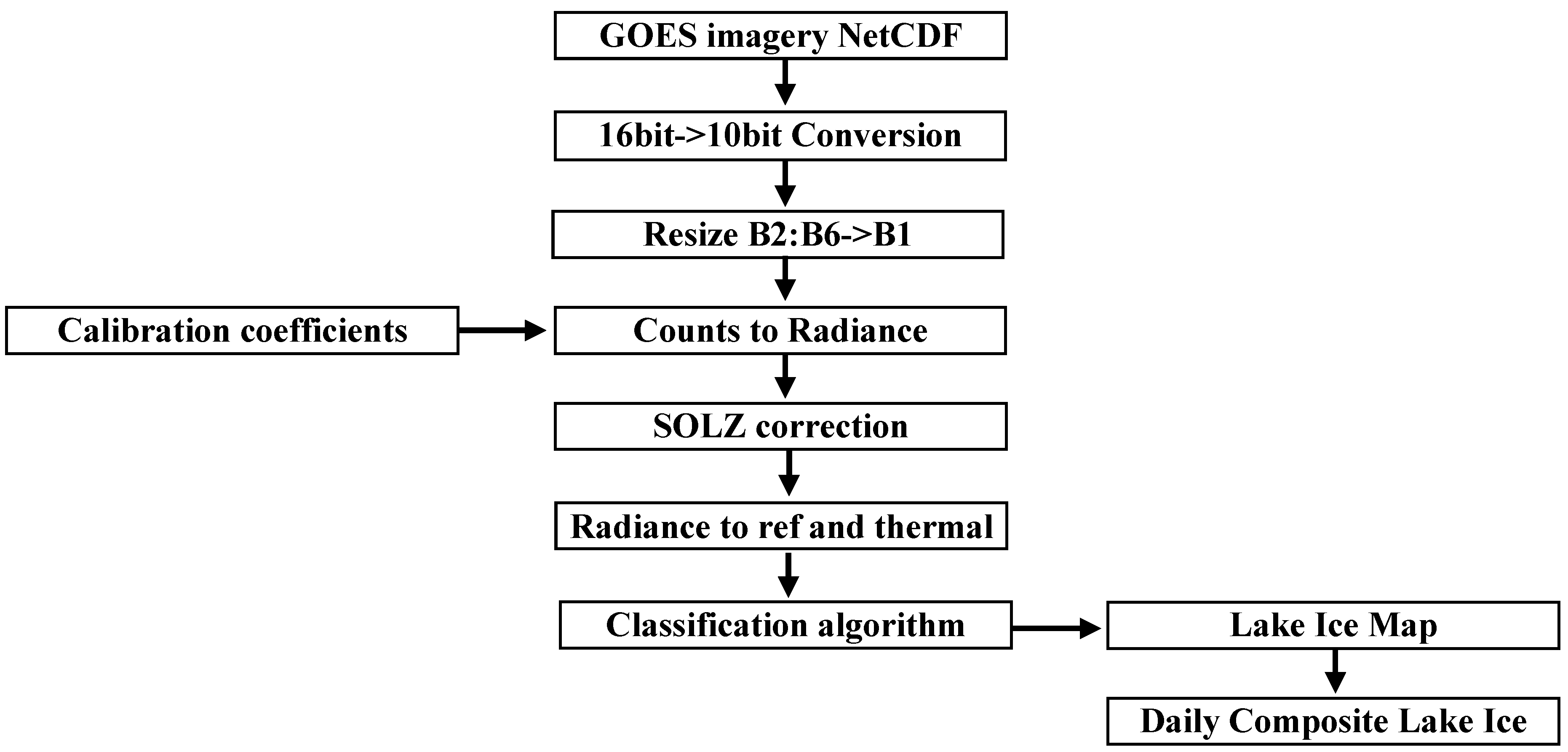
All channels except channel 3 are used in this study. GOES imagery is obtained from the NOAA Comprehensive Large Array-data Stewardship System (CLASS). The GOES imager GVAR (GOES Variable Format) sensor counts are stored as 10-bit. The data is downloaded as a netCDF file. The original 10-bit data were converted to 16-bit to be stored as netCDF (netCDF data is stored as 16-bit). A conversion is therefore made from 16-bit back to the original 10-bit. Data from channels 2 through 6 were resized to 1 km resolution to fit the spatial resolution of channel 1 data. Bicubic interpolation was applied in the transformation. Counts were converted to radiance using the calibration procedure provided by NOAA’s Office of Satellite and Product Operations (OSPO).
In order to build a robust ice classification model, it is vital that frequent observations are made throughout the day; thereby increasing the chance of obtaining cloud-free pixels. A daily composite image with significant reduction in cloud contamination can then be built. Data acquisition times are every half-hour from 1600 UTC to 2030 UTC. These are the times that GOES-13 is in the continental US (CONUS) extended scan mode with the exclusion of near 18:00 UTC which is during the time GOES-13 is operating in full disc mode. These times also correspond to daytime conditions over the eastern half of the North American continent.

2.2. Approach and Algorithm Development

The approach used in the algorithm development includes image classification. The classification is based on specific spectral criteria. Thick ice and snow will have relatively high reflectivity in the VIS, but noticeably lower reflectivity in the MIR. It is these specific differences in spectral signatures that are the physical basis for identifying and discerning between thin and or broken ice and thicker ice. Incorporating this identification scheme may allow researchers to use historical GOES data to construct past ice classification maps.

2.2.1. VIS and MIR Reflectance

GOES-13 channels 1 and 2, VIS (0.62 µm) and MIR (3.9 µm), are used in the development of MISI. Both snow and clouds have high reflectance values in the visible, with generally higher values for snow. Snow, thick ice, and cloud reflectances decrease with increasing wavelength in the VIS to SWIR spectrum; this decrease in reflectance is more significant with snow near 1.5 µm. The GOES imager does not operate in the 1.6 µm band; however, it does in the MIR 3.9 µm band. The daytime 3.9 µm band contains contributions from both solar reflection and thermal emission. A significant challenge in this study is to derive the 3.9 µm solar reflective component.
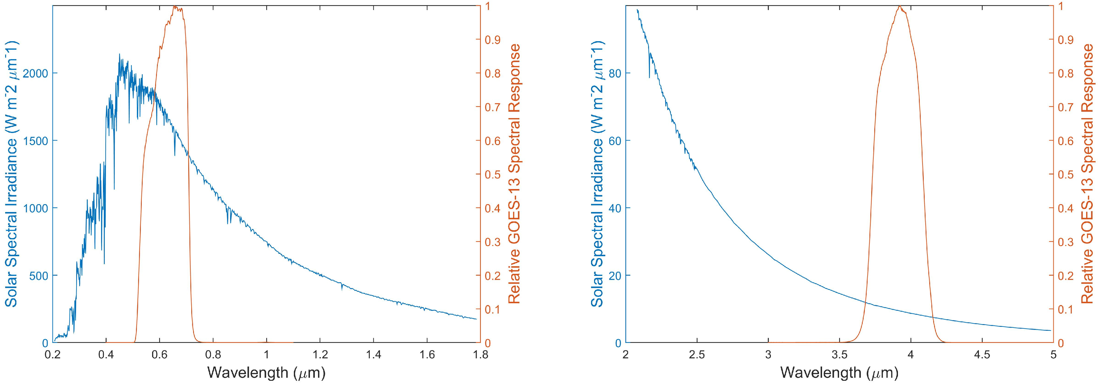
Figure 2 is a comparison of GOES-13 channel spectral response for the VIS (left) and MIR (right) channels with solar spectral irradiance. The incident radiance for a particular channel is the solar spectral irradiance averaged over the spectral response for that channel:
R i = λ m i n λ m a x S λ W λ   d λ λ m i n λ m a x W λ   d λ ,
where R i is the incident radiance (Watts/meter2) on the channel, S λ is the solar spectra irradiance, and W λ is the spectral response, or weighting function of the channel’s imaging sensor. The limits are determined by W λ . For the GOES-13 VIS channel, [λmin, λmax] = [0.399, 1.099 µm] and for the MIR channel, [λmin, λmax] = [2.99, 4.99 µm].
From the data as visualized in Figure 2, R i = 1656 W/m2 for the VIS and R i = 9.3 W/m2 for the MIR. These values are an approximation using Matlab (version)’s trapezoidal numerical integration method. R i for the VIS is in good agreement with NOAA’s OSPO value of 1657 W/m2 for the GOES-13 VIS channel. The calculated R i for the MIR has not been verified, as a means of validation has not been reached; however, this value for R i is used in this study.
R i is the incident solar radiance within the sensor spectral band. The outgoing radiance observed by the satellite sensor is attenuated and requires a geometric correction in the VIS, which accounts for solar altitude, and atmospheric absorption correction for the MIR, which accounts for CO2 absorption. The data has been processed with these corrections.
First the correction for the solar zenith angle is applied to VIS using a correction formula:
ρ = R   d 2 R i cos ( θ ) ,
where R is the scene radiance as calculated from the imager data and calibration coefficients, θ is the solar zenith angle, ρ is the corrected reflectance value, and d is the Earth–Sun distance in Astronomical Units (AU). Even though this distance changes slightly throughout the year, for simplicity in this study, d = 1 . In the remainder of this paper, ρ for VIS will be referred to as R1.
It should be apparent from Figure 2 that R i of MIR is significantly smaller than that of the VIS. Any useful information from this R i is more susceptible to both noise in the algorithm, a result of approximation methods, and signal noise in the sensor.
In order to derive the channel 2, 3.9 µm reflectance, the emitted component has been subtracted from the measured radiation through Planck’s relation, using the channel 4, 10.7 µm, brightness temperature (BT) [14]. The full implementation of this procedure in this study is a multistep process.
The conversion of the thermal component of the MIR to radiance is:
R 3.9 t h e r m a l = C 1 λ 3 ( e c 2 / λ T 1 ) ,
The spectral radiance is a function of wavelength ( λ ) and the surface temperature ( T ). T is the BT10.7 as derived from the inverse Planck function using the conversion coefficients of IR3.9. C 1 and C 2 are constants, 1.19 × 10⁻⁵ (mW/m2 sr cm−4) and 1.44 (K cm), respectively.
As was mentioned previously, some of the radiance in the 3.9 µm band may be lost to atmospheric absorption by the time it reaches the sensor. The primary absorber in this particular band is CO2. Since both the reflective and thermal IR3.9 components contribute to the radiance, a CO2 corrective coefficient is applied to both components. The CO2 correction in the thermal may be estimated from the brightness channels of the 10.7 and 13.3 µm bands:
R 3.9 c o r r = [ B T 10.7 0.25 ( B T 10.7 B T I R 13.3 ) ] 4 ( B T I R 10.7 ) 4 ,
With the correction applied:
R 3.9 t h e r m a l = R 3.9 t h e r m a l   R 3.9 c o r r ,
Unlike thermal radiation, which is attenuated from surface to satellite, the radiation contributing to solar reflection is attenuated in both sun to surface and surface to satellite. This correction is estimated from the following:
α = e ( 1 R 3.9 c o r r )   e ( 1 R 3.9 c o r r )   cos ( θ ) cos ( ϕ )   ,
The first term is the CO2 attenuation from surface to satellite and the second term is the CO2 attenuation from sun to surface, where θ is the solar zenith angle and ϕ is the satellite zenith angle.
Therefore, the top of atmosphere (TOA) reflectance with the CO2 correction is:
T O A C O 2 _ c o r r = R i π cos ( θ )   α .
Finally, the reflective component of the MIR channel is:
ρ = R 3.9 R 3.9 t h e r m a l T O A C O 2 _ c o r r   R 3.9 t h e r m a l .
In the remainder of this paper, ρ for MIR will be referred to as R2. Equations (4)–(8) have been adopted from the European Organization for the Exploitation of Meteorological Satellites (EUMETSAT) Meteosat conversion algorithms [18].
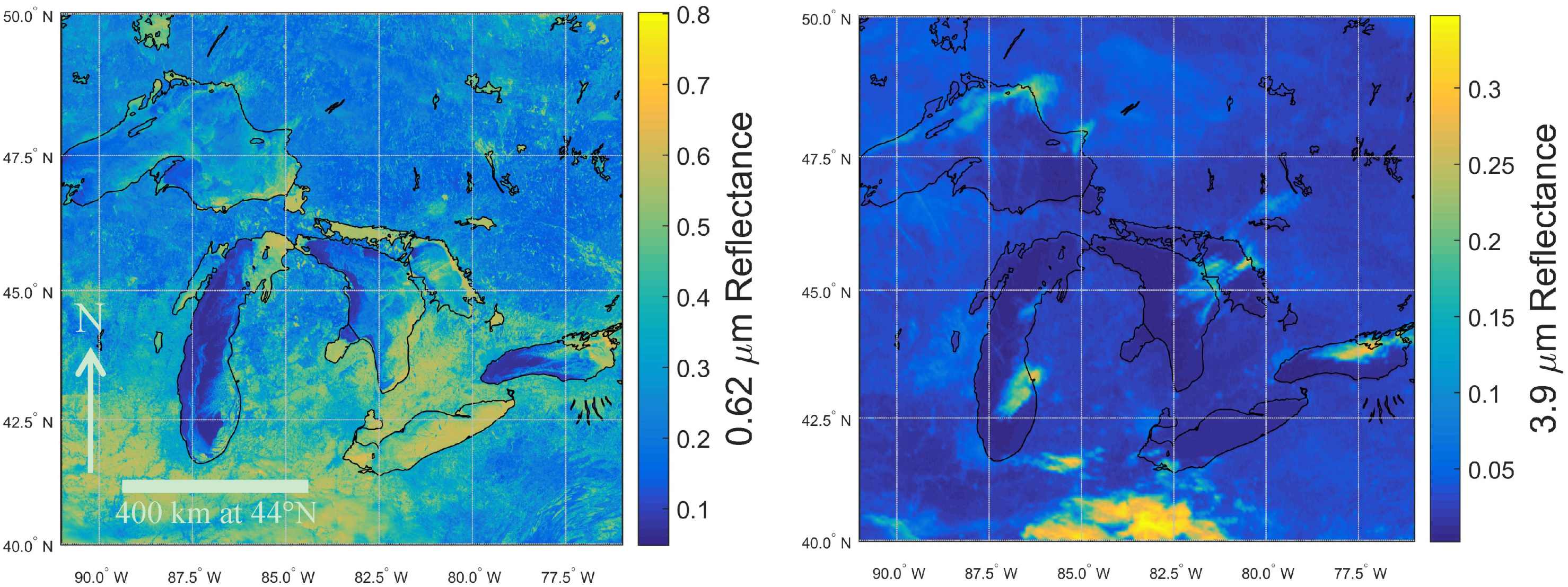
Figure 3 presents an example of GOES Imager corrected images in VIS and MIR. Yellow areas on the Great Lakes in the 0.62 µm band image are indicative of the high reflective values of snow, thick ice, and clouds. Even though a cloud mask has not been applied, it is apparent that Lake Erie is partially ice covered. Some ice can also be seen on eastern Lake Superior, northern Lake Michigan, parts of Lake Huron, and eastern Lake Ontario. Blue indicates lower reflective values of water and thin/broken ice. The right side is the derived 3.9 µm reflective. Comparison of the two images reveals a clear contrast of clouds and snow/ice. In the R2, clouds are yellow and snow/ice is deep blue.
The use of R2 in cloud identification has aided in the selection of a scene with minimal cloud contamination. This is evident in Figure 4 which shows the middle image, on February 28, to have less cloud contamination over the Great Lakes. As such, February 28 was selected for algorithm development.

2.2.2. Skin Temperature

A single channel method is used to estimate the temperature of the emitting surface, or “skin” temperature (ST). In the absence of clouds or atmospheric attenuation, and with a surface emissivity near unity, the brightness temperature should approximately equal to the skin temperature. Data from the GOES 13 channel 4 (10.7 µm) has been acquired and processed. Within the scope of this paper, no form of atmospheric attenuation for water vapor absorption has been applied. The results of the uncorrected brightness temperature are expected to at best be marginally cooler than the actual ST.
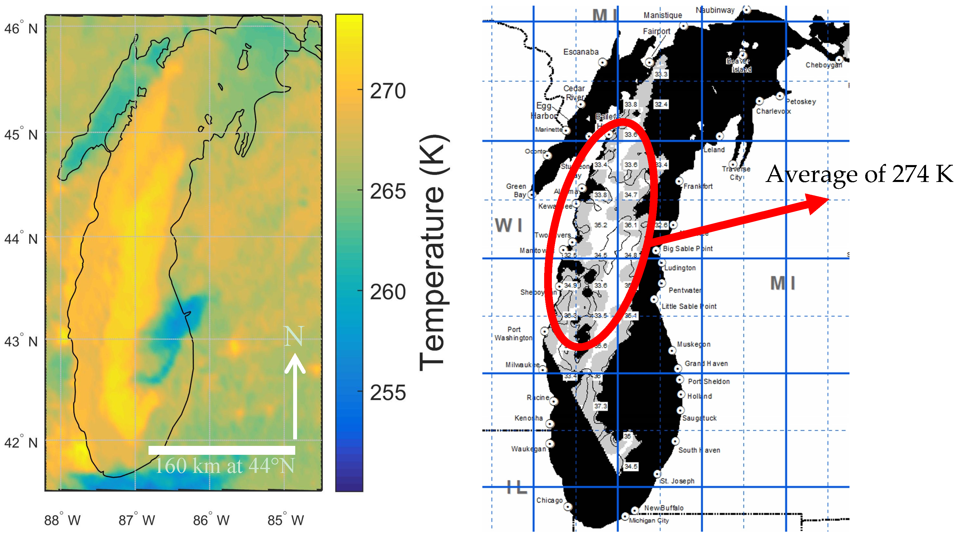
Figure 5 illustrates the single channel method of approximating ST for Lake Michigan from GOES (left). The right figure is a surface temperature map from Michigan State University (MSU) [19]. The MSU estimates are generated from satellite sensors. The area circled on the MSU map encapsulates temperatures between 273 and 275 K. A visual comparison of these two figures shows reasonable agreement. The assumption that is made from this simple qualitative validation is that, for cold water bodies with low presence of water vapor, the single-channel method will produce a reasonable indicator of ST for classification purposes.
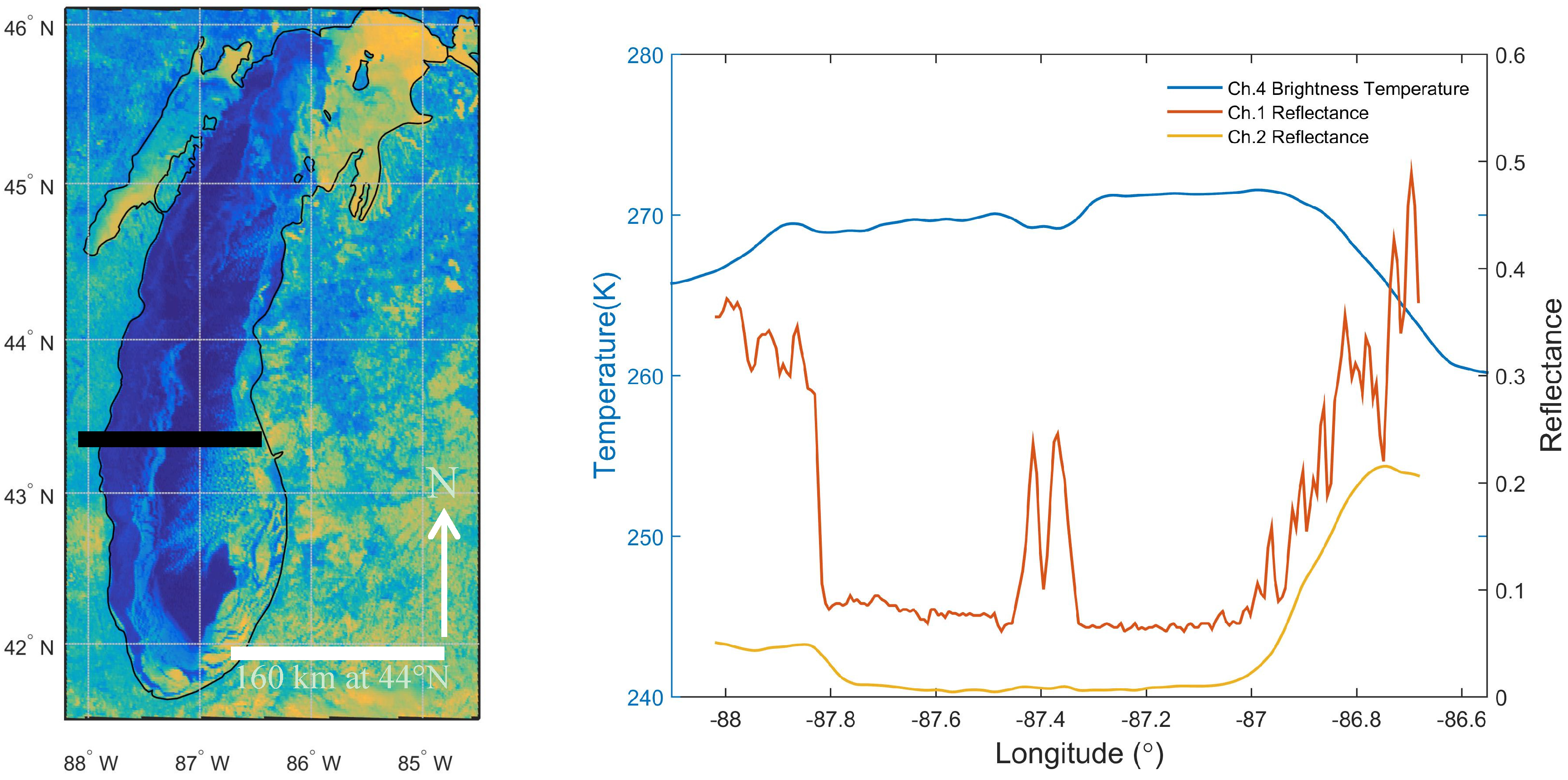
Figure 6 shows a visible image of Lake Michigan and a west-east cross-section profile of R1, R2, and ST (channel 4 brightness temperature) from the west shore until cloud coverage (approaching the east edge). A number of features are captured in this sampling: land snow, lake ice, liquid water, and cloud. The sampling is represented in the left figure by a black bar stretching from about 88° to 86.7° west longitude. The temperature for ice/liquid water is near 271 K, which is to be expected from the single-channel method. Snow land appears colder than lake ice, whereas cloud is the coldest feature in this scene.
Water/gray ice appears along a stretch from about 88° to 87.5°, with thick ice and/or snow cover centered near about 87.4°, and again water/gray ice from 87.3° to 87°. The spectral properties of liquid water, gray ice, and “thick” ice are similar in 3.9 µm. The reflectance in the 3.9 µm is near 0.05. In the 0.62 µm channel, the reflectance of gray ice and water is just under 0.1, whereas thick ice/snow exceeds 0.1. Using a temperature threshold of 271 K to distinguish between liquid water and ice, it may also be reasonable to conclude that gray ice is more likely to be near 87.6° and liquid water near 87.2°. A more robust method to derive skin temperature should provide a value closer to 273 K. In turn, this may also help to recover some of the information lost in R2 during the approximations. It is interesting to note that the reflectivity of R1 for gray ice approaches R2. From the above profile it is evident that R1/R2 >> 1.0 for snow or thick ice and that R1/R2 may be approaching unity for gray ice.

2.2.3. Snow Index

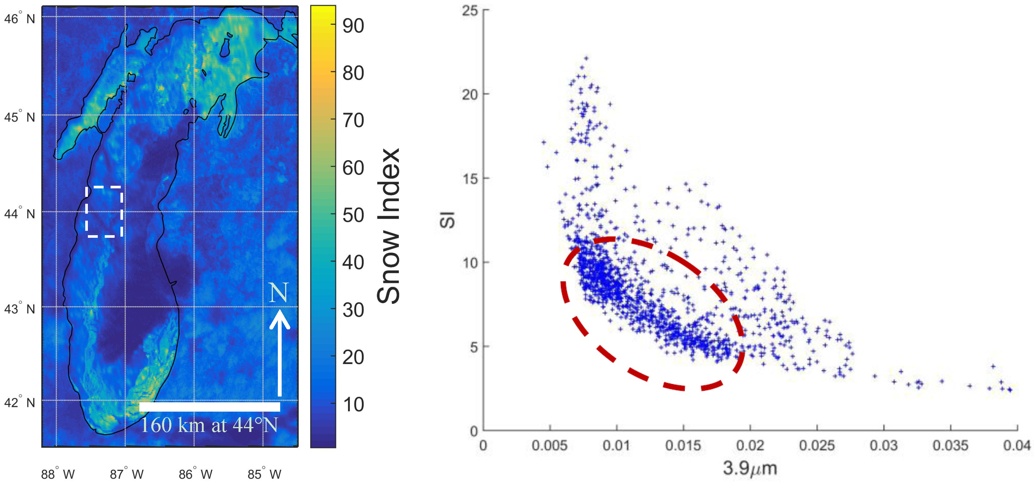
GOES NDSI using the 3.9 µm reflectance will vary within a small range close to unity. An alternative is the ratio of R1 to R2, called the snow index (SI = R1/R2) [10]. A demonstration of this is given in Figure 7. Figure 7 (left) is the snow index for Lake Michigan. The right figure is a scatter plot of the snow index and R2. The pixel sampling region (32 × 42) is indicated by the white box in the left figure. It is assumed that the sample is a mixture of water, ice, and snow. The greatest density in the scatter plot (indicated by the red oval) appears when the SI is between about 4 and 12. The sample plot appears asymptotic, with the lowest SI (R1/R2) value approaching 2.4 at a relatively high value of R2.
The application of SI for lake (or sea) ice mapping is a goal of this study. Therefore, the ratio of R1/R2 as it relates to sea and lake ice mapping is referred to as MISI. The algorithm proposed in this study is a variation to the one proposed by Romanov [10]. In that study, the SI for snow > 4.5. This seems to be in agreement with the above scatter plot, if it is assumed that the pixels encapsulated by the red circle are snow or thick ice; this dense region appears to begin near 4.5. Key relationships are the following: R1gray ice < R1ice, R2gray ice ~ R2ice and MISIgray ice < MISIice. “Ice” as opposed to “gray ice” refers to thick ice with or without snow cover. Unlike the MISI for snow or thick ice which will have values significantly greater than unity, MISI values of gray ice may have values approaching unity.

2.2.4. Threshold Determination

The distinction between the many surface types in a scene comes from the variation in spectral properties. Here we use various thresholds in the classification scheme. The snow index and R1 thresholds were determined through a visual inspection of the reflectance for a sampling of pixels from southern Lake Michigan. The sampling consists of a mixture of water and ice pixels. Fifty water pixels and 50 ice pixels were identified. The data are best fit to a normal distribution, as illustrated in Figure 8 for R1 and MISI. The means and standard deviations are provided in the figures. Blue is water, and red is ice. The distributions show a clear distinction in the mean values between water and ice. The ambiguity occurs where both distributions overlap. The overlap indicates that a pixel has a probability of being water or ice. For the scope of this paper, the point of intersection is chosen as a threshold value [20]. All data values above this point are classified as ice and all data values below this point are classified as water. A scatterplot for R2 did not prove useful as both ice and water distributions almost completely overlap. This is to be expected as the R2 values for ice and water are similar (Figure 6).

2.2.5. Classification Algorithm

A decision tree routine has been employed on a pixel-by-pixel basis. Figure 9 illustrates the flowchart of the developed decision tree algorithm. Ice, gray ice, water, and cloud pixels are classified.
All pixels are first evaluated for “thick ice”. The low threshold for R1 helps to insure that all forms of ice are captured (indicated by the blue arrow) prior to being evaluated for gray ice. Gray ice can be thin and or broken ice. The major criteria in discriminating between “thicker” ice from gray ice at this stage of the algorithm is based on the comparison in R1 reflectance (R1ice > R1gray ice) and the R1/R2 ratio (MISI). Pixels with smaller than the threshold values of MISI are classified as gray ice. Ice pixels with the MISI value larger than the threshold are classified as thick ice. All other pixels that are not cloud, water, ice, or gray ice are unclassified. The particular threshold values for R1 and MISI in this example have been estimated from the PDFs as presented in Figure 8. It should be noted that an evaluation of data at other times, which corresponds to different solar elevations, will likely produce different thresholds. An evaluation of thresholds across all acquisition times is recommended for future work. In addition, a MISI threshold of 4.5 to delineate thick ice/gray ice was initially evaluated in the algorithm which did result in some delineation; however, there were a substantial number of unclassified pixels left in the scene. Figure 10 is a flowchart of the entire data processing method.

3. Results

Figure 11 shows lake ice maps from 1600 UTC to 2030 UTC at half-hour increments (with the exception of 1800 UTC). The model produces four classes: water, gray ice, ice, and cloud. Unclassified pixels remain black. There are a substantial number of unclassified pixels in northwestern Lake Superior. This may be due in part to supervised threshold monitoring for this study only occurring for Lake Michigan. The thresholds were obtained from the sampling of pixels in Lake Michigan (PDF is shown in Figure 8) and simply applied to all five Great Lakes. Future work is suggested to partition the data and obtain an individual threshold for each of the Great Lakes.
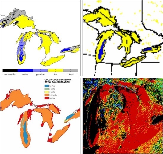
Figure 12 (left) is the final daily composite lake ice map. Compared with the mapping above, the daily composite map has far fewer unclassified pixels, which is clearly evident in Lake Superior. During the classification compositing process, pixels that are classified as ice or water persist. This map has been compared with the IMS snow and ice map and shows good agreement. In addition to thick ice, the model developed in this study includes gray ice.
The middle right image compares the lake ice map with the National Ice Center (NIC) ice concentration. The interpretation of gray ice is to be inclusive of thin and/or broken ice. The bottom right image compares the lake ice map with the MODIS snow and ice product. The model generally agrees with MODIS. Compared to the MODIS product, the model includes both gray and thick ice classification. Both products appear to reveal thick ice or snow extending North–South near the center of Lake Michigan, as indicated by the circles. Unlike MODIS, the model reveals gray ice along the east coast of Lake Huron, also indicated by circles. There is some discrepancy in water and ice pixels, most noticeably in Lake Michigan.
A detailed quantitative validation will be required for a more complete evaluation of the ice mapping system, including additional test scenes. Additional time-dependent threshold values for R1 and MISI are also recommended. An issue that comes up with the current version of the algorithm is that pixel classification may be overwritten during the iteration. This may be solved by implementing a binary response method in determining a particular classification for each pixel at each time. At the end of the iteration, the algorithm can simply compare the number of positive responses for each “possible” classification of each pixel and assign that pixel the classification that received the majority of positive responses.

4. Conclusions

Comparison of the final products with the Interactive Multisensor Snow and Ice Mapping System (IMS) maps show that the proposed model has high potential in lake ice mapping with a higher spatial resolution than IMS. While the MODIS snow product has even higher resolution, the temporal resolution of GOES-13 allows for better cloud contamination resilience. The model also demonstrates a more comprehensive product in that it includes both gray ice and thick ice. The mid-infrared sea and lake ice index (MISI) is the primary method for identifying gray and thick ice. MISI is the ratio of the visible reflectance to the derived reflective component of the mid-IR. From cross sectional profiles of the visible and in the mid-IR reflectance that were analyzed, thick ice and/or snow cover consistently showed higher than unity values, whereas gray ice shows values approaching unity.
One of the principle motivations of this project is to contribute to the GOES-R satellite research and product development. GOES-R, which launched in November 2016, has increased temporal and spatial resolution and includes not only the 1.6 µm band currently used in traditional NDSI snow mapping, but also a 3.9 µm band, which has been the focus of this paper for lake ice mapping. The algorithm may open up a new era in the capabilities of ice mapping systems and climate studies using historical GOES imagery data and other satellite sensors that do not have a 1.6-µm channel.

Acknowledgments

This work was funded by Rowan University and NOAA. The views, opinions, and findings contained in this report are those of the author(s) and should not be construed as an official National Oceanic and Atmospheric Administration or U.S. Government position, policy, or decision. We want to express our gratitude to the undergraduate students at Rowan University: Matthew Grosmick, Godfrey Joyner, and Andrew Plucinsky for assisting with data collection.

Author Contributions

Peter Dorofy designed the research, collected the data, implemented the data analysis, and wrote the manuscript. Rouzbeh Nazari advised the whole study and made revisions to the manuscript. Peter Romanov and Jeffrey Key provided additional scientific advisement and made revisions to the manuscript.

Conflicts of Interest

The authors declare no conflict of interest.

References

  1. National Snow and Ice Data Center. Available online: https://nsidc.org/cryosphere/seaice/characteristics/formation.html (accessed on 1 September 2016).
  2. Zeng, Q.; Cao, M.; Feng, X.; Liang, F.; Chen, X.; Sheng, W. A study of spectral reflection characteristics for snow, ice and water in the north of China. Hydrol. Appl. Remote Sens. Remote Data Transm. 1984, 145, 451–462. [Google Scholar]
  3. Salisbury, J.W.; D’Aria, D.M.; Wald, A. Measurements of thermal infrared spectral reflectance. J. Geophys. Res. 1994, 99, 24235–24240. [Google Scholar] [CrossRef]
  4. Perovich, D.K. The Optical Properties of Sea Ice; No. MONO-96–1; Army Cold Regions Research and Engineering Lab: Hanover, NH, USA, 1996; pp. 8–9.
  5. Perovich, D.K. The Optical Properties of Young Sea Ice; No. SCIENTIFIC-17; Washington Univ Seattle Dept of Atmospheric Sciences: Seattle, WA, USA, 1979; p. 71. [Google Scholar]
  6. Perovich, D.K.; Roesler, C.S.; Pegau, W.S. Variability in Arctic sea ice optical properties. J. Geophys. Res. Ocean. 1998, 103, 1193–1208. [Google Scholar] [CrossRef]
  7. Valovcin, F.R. Snow/Cloud Discrimination; No. AFGL-TR-76–0174; Air Force Geophysics Lab, Hanscom AFB: Bedford, MA, USA, 1976; p. 13.
  8. Kyle, H.L.; Curran, R.J.; Barnes, W.L.; Escoe, D. A cloud physics radiometer. In Proceedings of the 3rd Conference on Atmospheric Radiation, Boston, MA, USA, 28–30 June 1978; pp. 107–109.
  9. Dozier, J. Spectral signature of alpine snow cover from the Landsat Thematic Mapper. Remote Sens. Environ. 1989, 28, 9–22. [Google Scholar] [CrossRef]
  10. Hall, D.K.; Riggs, G.A.; Salomonson, V.V. Development of methods for mapping global snow cover using moderate resolution imaging spectroradiometer data. Remote Sens. Environ. 1995, 54, 127–140. [Google Scholar] [CrossRef]
  11. Liu, Y.; Key, J.; Mahoney, R. Sea and freshwater ice concentration from VIIRS on Suomi NPP and the future JPSS satellites. Remote Sens. 2016, 8, 523. [Google Scholar] [CrossRef]
  12. Riggs, G.; Hall, D.K. Snow mapping with the MODIS Aqua instrument. In Proceedings of the 61st Eastern Snow Conference, Portland, ME, USA, 9–11 June 2004.
  13. Haq, M.A.; Jain, K.; Menon, K.P.R. Development of new thermal ratio index for snow/ice identification. Int. J. Soft Comput. Eng. 2012, 1, 2231–2307. [Google Scholar]
  14. Allen, R.C., Jr.; Durkee, P.A.; Wash, C.H. Snow/cloud discrimination with multispectral satellite measurements. J. Appl. Meteorol. 1990, 29, 994–1004. [Google Scholar] [CrossRef]
  15. Key, J.; Barry, R.G. Cloud cover analysis with Arctic AVHRR data: 1. Cloud detection. J. Geophys. Research Atmos. 1989, 94, 18521–18535. [Google Scholar] [CrossRef]
  16. Romanov, P.; Gutman, G.; Csiszar, I. Automated monitoring of snow cover over North America with multispectral satellite data. J. Appl. Meteorol. 2000, 39, 1866–1880. [Google Scholar] [CrossRef]
  17. Lee, J.; Chung, C.; Ou, M. Evaluation of the Geostationary Satellite Based Snow and Sea Ice Detection Algorithm; Gisangcheong-gil 45; National Institute of Meteorological Research/Korea Meteorological Administration: Seoul, Korea, 2015.
  18. European Organization for the Exploitation of Meteorological Satellites (EUMETSAT). MSG Channels. Available online: http://oiswww.eumetsat.org/WEBOPS/msg_interpretation/msg_channels.php (accessed on 1 September 2016).
  19. Michigan Sea Grant Coastwatch. Lake Michigan Surface Temperature. Available online: http://www.coastwatch.msu.edu/michigan/archive/m/Feb28/2015_Feb28_1254EDT.gif (accessed on 1 September 2016).
  20. Ghedira, H.; Khanbilvardi, R.; Romanov, P. Development of an advanced technique for mapping and monitoring sea and lake ice for the future GOES-R Advanced Baseline Imager (ABI). In Proceedings of the 2007 IEEE International Geoscience and Remote Sensing Symposium, Barcelona, Spain, 23–28 July 2007.
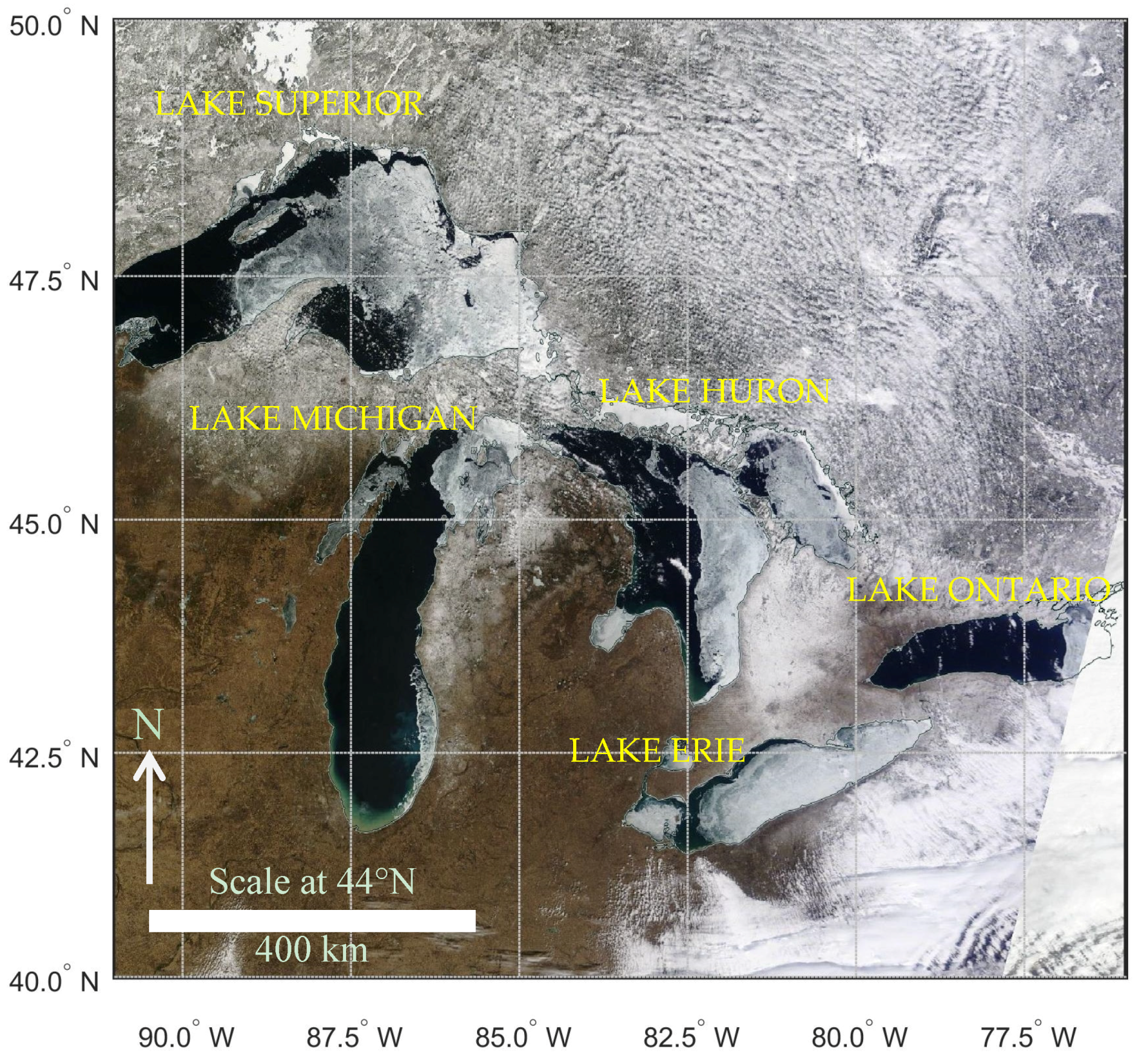
Figure 1. Ice cover on the Great Lakes. Image acquired on 17 March 2015 (NASA).
Remotesensing 08 01015 g001
Figure 2. GOES channel spectral response and solar spectral irradiance: (left) 0.62 channel; (right) 3.9 channel.
Remotesensing 08 01015 g002
Figure 3. (Left) 28 February 2015 0.62 µm reflectance at 1830 UTC; (right) 3.9 µm reflective component.
Remotesensing 08 01015 g003
Figure 4. 3.9 µm reflective at 1830 UTC for 27 February–1 March 2015. Bright yellows are high R2 values indicative of clouds.
Remotesensing 08 01015 g004
Figure 5. ST of Lake Michigan on 28 February 2015: (left) ST at 1730 UTC; (right) surface temperature map at 1754 UTC from Coastwatch at Michigan State University.
Remotesensing 08 01015 g005
Figure 6. (Left) 0.62 µm image of Lake Michigan at 1830 UTC on 28 February 2015; (right) the R1, R2, ST profile along the cross section indicated by the black line on the left figure.
Remotesensing 08 01015 g006
Figure 7. (Left) Snow Index (SI) for 1830 UTC on 28 February 2015; (right) scatter plot of the snow index to the 3.9 µm. The pixel sampling region (32 × 42) is indicated by the white box in the left figure.
Remotesensing 08 01015 g007
Figure 8. Probability distribution functions of water (blue) and ice (red) at 1830 UTC on 28 February 2015: (left) distribution of reflectance; (right) distribution of snow index.
Remotesensing 08 01015 g008
Figure 9. GOES snow/ice detection algorithm.
Remotesensing 08 01015 g009
Figure 10. Data processing flow.
Remotesensing 08 01015 g010
Figure 11. Lake ice maps at half-hour acquisition times (with the exception of 1800 UTC).
Remotesensing 08 01015 g011
Figure 12. (top, left) Lake ice daily composite map; (top, right) IMS Snow map: white is snow, yellow is ice, blue is water; (bottom, left) National Ice Center ice concentration: blue is ice-free, red is fast ice; (bottom, right) MODIS snow and ice cover: red is more, yellow is less.
Remotesensing 08 01015 g012
Table 1. GOES-13 imager channels.
GOES-13 Imager
Channel #1 (VIS)2 (MIR)3 (Moisture)4 (IR1)6 (IR2)
Wavelength Range (µm)0.54–0.713.73–4.085.90–7.2810.19–11.1813.00–13.71
Central Wavelength (µm)0.623.906.5410.713.34
Instantaneous Field of View (IFOV), km14444