Controlling Interfacial Adhesion of Self-Assembled Polypeptide Fibrils for Novel Nanoelectromechanical System (NEMS) Applications

Abstract
: The relative adhesion of two genetically engineered polypeptides termed as H6-(YEHK)x21-H6 and C6-(YEHK)X21-H6 has been investigated following growth and self-assembly on highly oriented pyrolytic graphite (HOPG), SiO2, Ni, and Au substrates to study covalent surface attachment via histidine (H) and cysteine (C) groups incorporated in the polypeptides. Both polypeptides formed predominantly bilayer fibrils upon deposition, in agreement with previous studies. The relative adhesion of polypeptide fibrils to the substrate, as well as intra-fibril cohesion, was examined via a forced-scanning method employing contact mode atomic force microscopy (AFM). H6-(YEHK)x21-H6 polypeptide fibrils were observed to detach from Ni, Au, SiO2, and HOPG substrates at normal tip forces of 106 ± 10 nN, 21 ± 3 nN, 22 ± 3 nN, and 3 ± 1 nN, respectively. C6-(YEHK)x21-H6 polypeptide fibrils were seen to detach from Au substrates at a normal spring force of 90 ± 10 nN. It is concluded that the H6-(YEHK)x21-H6 and C6-(YEHK)x21-H6 polypeptide fibrils are covalently attached to, respectively, Ni and Au substrates, which has important implications for the use of these materials for NEMS fabrication. The structural stability of deposited polypeptide fibrils was also evaluated by using normal tip forces less than those required for fibril detachment. H6-(YEHK)x21-H6 polypeptide fibrils on Ni substrates were the most structurally stable compared to C6-(YEHK)x21-H6 polypeptide fibrils on Au substrates. Controlled delayering of bilayer fibrils was also detected for sub-detachment normal forces.1. Introduction
Biologically-inspired materials offer great potential for use in a range of nano-electromechanical systems (NEMS), including invasive biodevices such as biosensors and nano-syringes, as well as for structural applications that take advantage of the unique mechanical and electrical properties of such materials. Moreover, these materials can be fabricated inexpensively in large quantities using well-controlled genetic engineering techniques, thus allowing atomic scale control over the size and form factor of the structure [1,2].
From a nanomaterials perspective, β-sheet polypeptides offer intriguing potential as one-dimensional nanostructures that can serve as nanoscaffolds supporting a variety of functional groups. With their precise, one-dimensional structure and predictable self-assembly, they represent potential building blocks for bottom-up fabrication and, conceivably, devices in so-called ‘bio-chips’. In the work presented herein, a genetic engineering approach has been applied to the synthesis of polypeptides [3,4]. These polypeptides have the propensity to form linear and predominantly bilayer fibrils [5], with the resulting nanostructures being able to potentially serve as mechanical supports, nanoprobes, nanowires, and/or templates for nanowires [6,7].
Understanding the interaction of these polypeptide-based nanostructures with metallic substrates, with emphasis on immobilization or attachment for NEMS applications is central to their technological viability. One approach considered for metallic attachment of peptide structures includes the use of histidine end groups. The dissociation constant (pKa) of histidine (also noted as (His)6 or H6) is 6.0–6.5 [8] and, at a pH of 7.0, the imidazole rings of the H6 are deprotonated, which allows the lone pair of electrons on the double bonded nitrogen of the imidazole ring to bind to divalent metals. Therefore, the hexahistidinal tract present at the end of the polypeptide molecules considered herein possesses an affinity towards divalent metal ions such as nickel (II) and copper (II), wherein a dative bond can be formed between the nitrogen atom on the imidazole ring and a Ni2+ or Cu2+ ion. However, due to factors including surface oxidation, the adhesion of such polypeptide molecules to nickel substrates is not well understood. Such an understanding clearly needs to be established for such fibrillar structures to be used in a practical fabrication process.
Adsorption of (S)-histidine molecules to Cu and oxygen modified Cu has been previously studied [9]. Due to steric considerations, the histidine groups studied in Reference 9 formed dative bonds with copper via the pyrrole-type nitrogen lone electron pair of the imidazole ring. The oxygen-modified copper surface favored the hydrogen bond between the local positive charge on the N-H functional group of the imidazole ring and the negative anionic charge on surface oxygen. Similar bonding mechanisms can be envisaged for nickel. In fact, Ni (II) ion chelation by nitriloacetic acid (NTA) is used to selectively bind polypeptides containing histidine residues to Ni-containing materials in chromatography. In the latter, a sequence of six histidine residues is commonly attached to the primary polypeptide sequence to isolate them from crude lysate by means of the Ni-NTA functionalized chromatographic matrix, and to immobilize them on biosensors [10]. Such an attachment is reversible and determined by the solution pH.
Histidine-tagged polypeptides have also been immobilized on gold surface via thiol-gold binding using thioalkane chains with a chelating group at the other end [11]. Consequently, an investigation of the nanoscale mechanics of direct immobilization of histidine-tagged (His-tagged) polypeptides on nickel is not only scientifically interesting, but technologically relevant.
Direct attachment of His-tagged polypeptides covalently coupled to fluorescent microspheres has been studied on glass, nitrocellulose, gold, unoxidized copper, and nickel substrates [12]. High-velocity laminar flow testing has been used to evaluate the adhesion strength of these his-tagged microspheres to the substrates. Adhesion strength with nickel was reported to be the highest, with the shear force required to remove 66% of His-tagged microspheres being greater than 160 nN, compared to 41 nN, 53 nN, and 150 nN for, respectively, gold, glass and copper. However, this work did not isolate adhesion associated with individual molecules.
Nanoscale molecular adhesion can be measured by atomic force microscopy (AFM) in force calibration mode [13-15]. AFM has been used to evaluate the bond strength of the His-tag to various substrates. In this technique the tip is functionalized with a ligand incorporating a His-tag (e.g., His-tagged polypeptide). The tip is brought in contact with the substrate and retracted at various speeds. The force at which the molecular bond to the surface ruptures is recorded from the force curves. Significantly different binding strengths between histidine and Ni-NTA have been reported by different groups (38 pN, 180 pN, 240 pN and 500 pN) [16-19]. Bond rupture forces have been measured between His-tags and various substrates including Ni-NTA (pH: 6.0), Ni-NTA (pH: 7.2), Ni, and Au. Although single molecule adhesion can be measured with this technique, the latter is limited in its ability to develop an understanding of more complex (multiple) interactions of polypeptides or protein based nanostructures with specific substrates as it relates to absolute adhesion measurements.
Manipulation force microscopy (MFM) is another atomic force microscope based technique to measure the adhesion of proteins and living cells to surfaces [20-23]. In this technique, a protein is adsorbed on a rigid microsphere (polystyrene, silica) which is then displaced laterally against a cantilever held at a tilt of 30 degrees to the substrate surface normal. The cantilever deflection is noted optically. Displacement force and time are recorded. Protein adhesion force dynamics and single adhesion events have been measured in this fashion. Similar to the molecular adhesion techniques described above, manipulation force microscopy faces some limitations in exploring more general substrate geometries.
Instead, the current investigators employ an AFM-based approach similar to a generalized ‘scratch test’ for adhesion evaluation of His-tagged polypeptides on Ni substrates to specifically measure nanoscale adhesion of individual molecular assemblies. In this ‘forced-scanning’ method, an AFM is used in contact mode on an appropriately prepared surface with self-assembled polypeptide nanofibrils. The normal cantilever tip force required to displace the polypeptide material completely from the scan region on a substrate is recorded to compare the interfacial adhesion of the polypeptide nanostructures on different substrates. The structural stability of deposited polypeptide fibrils was also evaluated for normal tip forces less than that required for fibril detachment. H6-(YEHK)x21-H6 polypeptide fibrils on Ni substrates were the more structurally stable compared to C6-(YEHK)x21-H6 polypeptide fibrils on Au substrates. Controlled delayering of bilayer fibrils was also observed for sub-detachment normal forces.
2. Results and Discussion
2.1. Results
Polypeptides are known to predominantly assemble into bilayer fibrils. Tapping mode AFM topography and TEM analyses of these fibrils have already been published [5]. Due to tip contact and convolution effects, the lateral dimensions measured via contact-mode AFM—as applied herein for adhesion measurements—are generally larger than their AFM tapping mode counterparts.
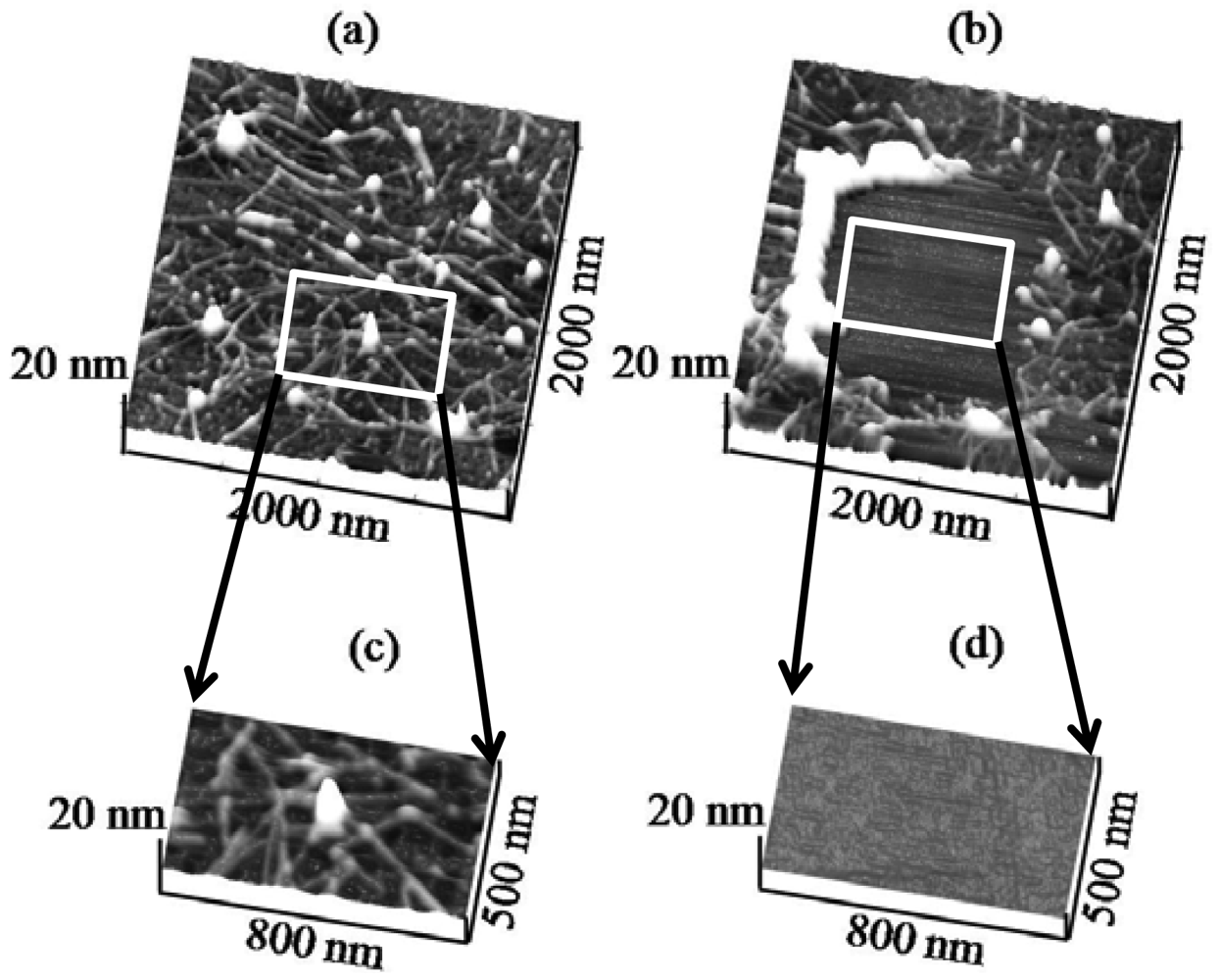
To this end, Figure 1a shows a contact mode AFM (CM-AFM) topography image of H6-(YEHK)x21-H6 bilayer fibrils on a HOPG substrate (2 μm × 2 μm scan size) acquired using a cantilever with a spring constant of 0.08 N/m. The size and conformation are consistent with earlier reports [5]. The normal force between the tip and the substrate was minimized for stable contact-mode imaging. Subsequently, the cantilever was scanned in the 1 μm × 1 μm central region at successively larger tip normal forces, in steps of 0.5 nN. Furthermore, Figure 1(b) indicates that for sufficiently high force values, the polypeptide fibrils were removed from the scan area [Figure 1(b)]. Additionally, Figure 1(c,d) shows a 500 nm × 800 nm region scanned at, respectively, zero force and at a normal tip force of 3 ± 1 nN. For the latter, the polypeptide material is completely displaced to the edges of the scan region. Only the cleared HOPG surface is apparent in the image. These measurements were repeated using a cantilever with spring constant of 0.58 N/m. Similarly, polypeptide material was completely removed from the scan area at 5 ± 2 nN.
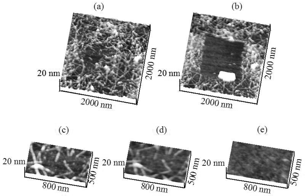
The adhesion of H6-(YEHK)x21-H6 to Ni substrates was similarly investigated. Figure 2(a) shows contact-mode topography images of H6-(YEHK)x21-H6 fibrils on a nickel substrate using a 0.58 N/m spring constant cantilever at zero force. AFM contact imaging at successively larger tip normal forces completely removed the fibrils from the scan region at a normal spring force of 106 ± 10 nN [Figure 2(b)]. In this context, Figure 2(c-e) shows the progression of polypeptide displacement from a 500 nm × 800 nm scan region. Figure 2(c) represents the topography imaged at zero normal tip force. Figure 2(d) shows the topography of the same region after scanning at a normal tip force of 40 nN, while Figure 2(e) depicts the total removal of polypeptide material from the scan region at a normal spring force exceeding 106 nN.
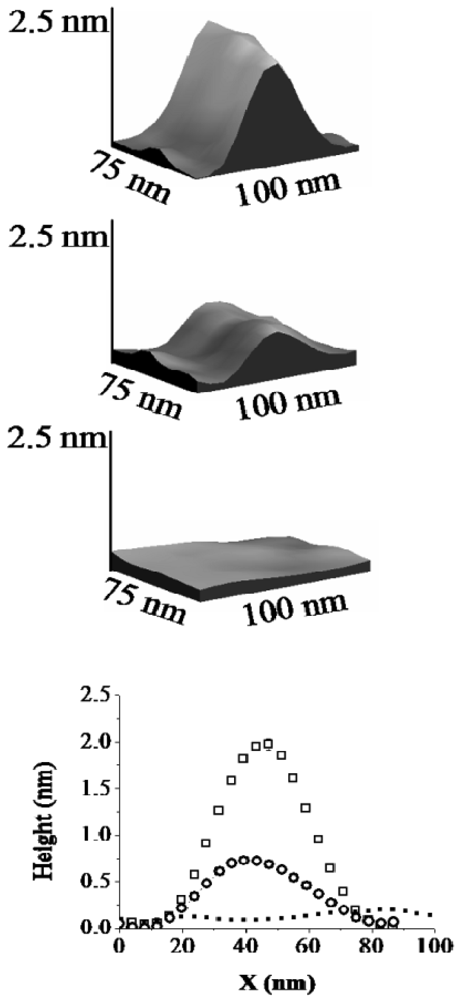
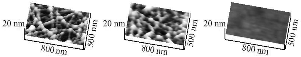
For H6-(YEHK)x21-H6 fibrils deposited on Ni substrates, the lateral configuration of the fibrils displayed only minor changes up to normal tip forces of approximately 70 nN. However, the measured thickness of selected fibrils was modified. This observation is illustrated in Figure 3 and Figure 4. Figure 3 shows a high-resolution 3D topographic image of an individual fibril taken at the zero normal tip force. The measured fibril thickness (∼2 nm) is consistent with a bilayer structure. As the normal tip force is increased to 40 ± 5 nN the lateral position of the H6-(YEHK)x21-H6 fibril remains unchanged, but the height is reduced to approximately 1 nm (Figure 3). Noticeable distortion in the stable polypeptide features on Ni surface was observed at normal tip forces near 70 nN. As the normal tip force is increased to 106 ± 10 nN the fibril is completely displaced from the scan area.
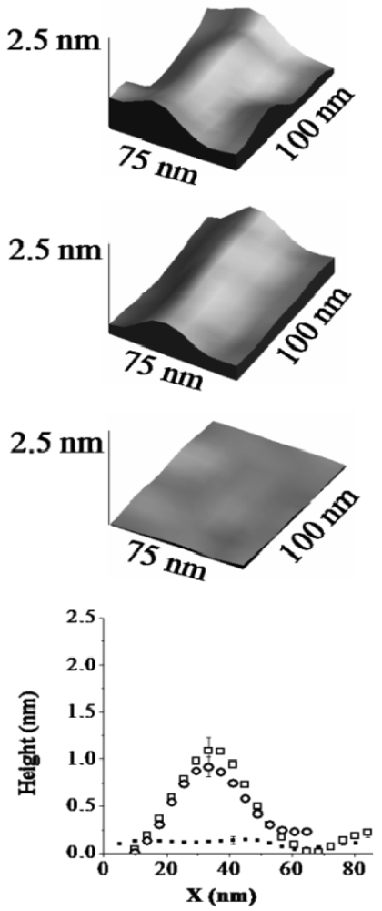
In a separate region of the sample, a monolayer H6-(YEHK)x21-H6 fibril was identified at zero force scanning (Figure 4). As the normal tip force is increased to approximately 40 nN for this monolayer fibril, no substantial change was seen in its lateral position or thickness. Upon scanning at 106 nN, the monolayer fibril was completely displaced from the scan area. The data in Figure 4 supports the conclusion that the change in fibril height seen in the data from Figure 3 corresponds to the removal of the top H6-(YEHK)x21-H6 layer by the tip. It also implies that the adhesive force between the bottom H6-(YEHK)x21-H6 layer and the substrate is more than double the cohesive strength of the bilayer.
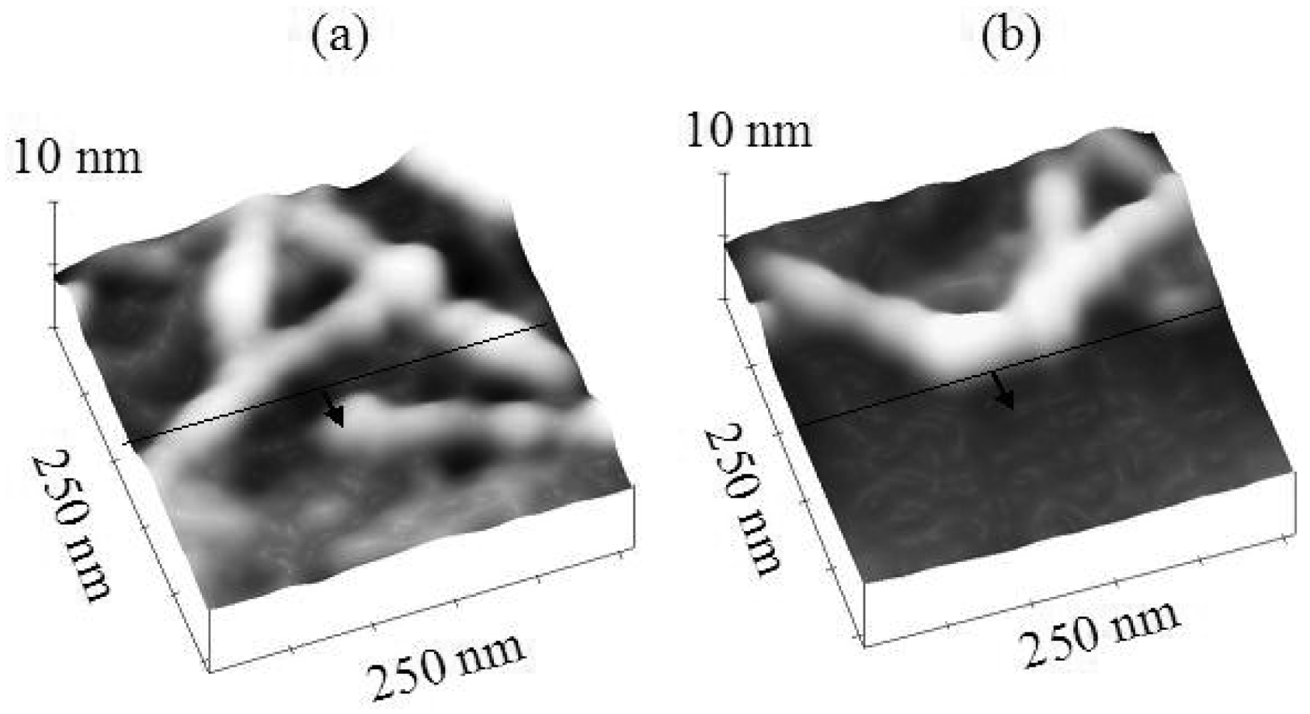
Figure 5 compares the topology changes of polypeptide features at the scan edges for Ni and HOPG substrates at a normal tip force of 40 nN. The black line drawn in the images represents the scan edge. The region below the line (denoted by the arrow) is the scan region. It is clear that the H6-(YEHK)x21-H6 polypeptide fibrils on nickel maintain their continuity across the scan edge during tip scanning at 40 nN. On HOPG, in contrast, the tip easily displaces (fractures) H6-(YEHK)x21-H6 fibrils at normal tip forces below 5 nN.
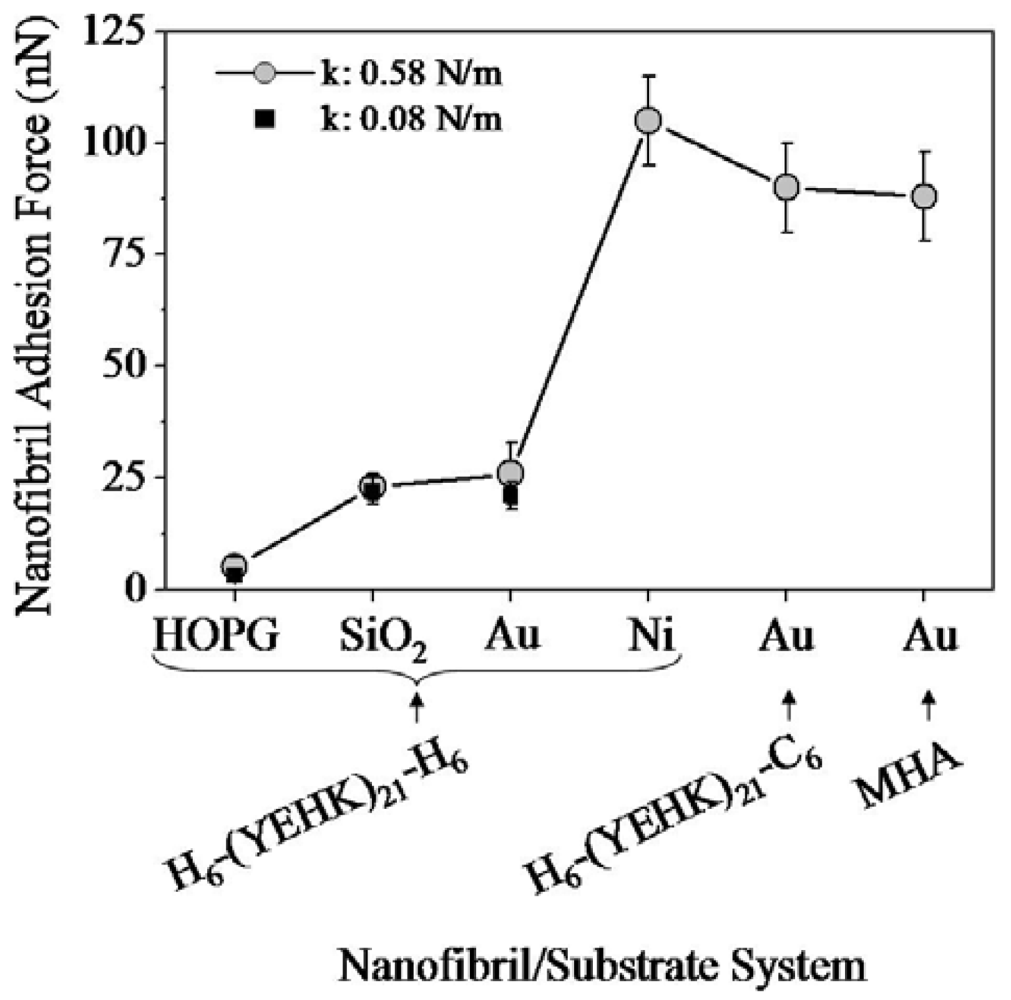
As a comparison with the results for adhesion of H6-(YEHK)x21-H6 on Ni substrates, forced-scan adhesion measurements were also carried out for the fibrils deposited on Au and SiO2 substrates, employing cantilevers with 0.08 N/m and 0.58 N/m spring constants as previously described. The low and high spring-constant tips resulted in the removal of polypeptide fibrils on Au substrates from the scan region at normal tip forces of, respectively, 21 ± 3 nN and 26 ± 7 nN. The same cantilevers applied to fibrils deposited on SiO2 resulted in their removal from the scan region at normal tip forces of, respectively, 22 ± 7 nN and 24 ± 3 nN. Although higher than the tip forces required for removal of fibrils from HOPG, these observations imply no adhesion differences of the H6-(YEHK)x21-H6 fibril to Au and SiO2 substrates, in clear contrast to the findings for Ni substrates.
The results above imply the existence of chemical bonding of H6-(YEHK)x21-H6 fibrils to the Ni substrate through the terminal hexahistidine groups and is discussed in more detail below. For purposes of comparison, a similar polypeptide was synthesized in which one hexahistidine group was replaced with a hexacysteine (“C6”) group (C6-(YEHK)x21-H6) to specifically gauge the resulting impact on adhesion to Au substrates due to the well-established Au-cysteine bond through the constituent thiol group. These polypeptides were observed to form linear fibrils similar to those of H6-(YEHK)x21-H6 (Figure 6). Forced-scan adhesion measurements were undertaken employing a cantilever with spring constant 0.58 N/m. All the C6-(YEHK)x21-H6 polypeptide material was displaced from the scan region at a normal tip force of 90 ± 10 nN (Figure 6). In contrast to the adhesion behavior of H6-(YEHK)x21-H6 polypeptide fibrils on nickel, forced-scanning at normal tip forces near 40 nN resulted in substantial deformation and displacement of C6-(YEHK)x21-H6 polypeptide fibrils on gold (Figure 6). Similar experiments were repeated with a lower spring constant cantilever (0.08 N/m). The onset of C6-(YEHK)x21-H6 deformation/displacement was observed at a normal tip force of 36 ± 4 nN.
For purposes of comparison and the establishment of quantitative conclusions regarding chemical bonding of polypeptide fibrils to individual substrates, a series of force-scan adhesion measurements were undertaken on self-assembled monolayers of 16-mercaptohexadecanoic acid (MHA). Figure 7 shows the topography resulting from forced scan imaging of the MHA monolayer on Au substrates (upper image in the figure). The right-hand side of the 3D topography image corresponds to the scan region. The MHA material from the scan region was displaced and accumulated at the scan edge. There is a relative height differential of 2 ± 0.3 nm between the scanned region and the non-scanned region (lower panel of Figure 7). This differential corresponds well to the expected thickness of 2.1 nm for a self-assembled MHA film for constituent molecules in an all-trans orientation [24]. Employing a cantilever with spring constant of 0.58 N/m, the MHA monolayer in the scan region was completely removed at a normal tip force of 88 ± 10 nN.
Figure 8 summarizes the normal tip forces required to completely displace H6-(YEHK)x21-H6 polypeptides fibrils on HOPG, SiO2, Au, and Ni substrates; C6-(YEHK)x21-H6 polypeptide fibrils on Au substrates; and MHA monolayer on Au substrates. This data is representative of the maximum adhesion for each material to a specific substrate. The square and circle symbols correspond to measurements resulting from cantilevers with spring constant of 0.08 N/m. and 0.58 N/m respectively. The maximum adhesion data acquired with the two cantilevers were consistent for cases of H6-(YEHK)x21-H6 polypeptide fibrils on HOPG, SiO2, and Au substrates where the normal spring force required to remove the material from the scan region was in the range of maximum applicable force by cantilever of spring constant 0.08 N/m. Data points for H6-(YEHK)x21-H6 and C6-(YEHK)x21-H6 polypeptides on Ni and Au substrates (square symbols in Figure 8) represent measurements using the high spring constant cantilever only, as the low spring constant cantilever could not be applied with sufficient normal tip force to completely displace the fibrils from the scan area.
2.2. Discussion
The adhesion of the H6-(YEHK)x21-H6 polypeptide to HOPG substrates was the weakest among all the materials/substrates studied, with a maximum normal tip force for molecular displacement below 5 nN. This result was not surprising, as the hydrophobic HOPG surface is relatively chemically inert and polypeptide materials bind to such surfaces via non-covalent interactions. In this context, His-tagged H6-(YEHK)x21-H6 polypeptides exhibited the strongest adhesion to Ni surfaces, as compared to other substrates, with normal tip forces in excess of 100 nN required to displace the fibrils—i.e., adhesion of such fibrils to Ni substrates is 20–30 times stronger than to HOPG substrates. The relative adhesion of H6-(YEHK)x21-H6 to Au and SiO2 substrates, although substantially larger than for HOPG, was small compared to Ni in agreement with previously published results for His-tagged polypeptides on gold and glass [6]. C6-(YEHK)x21-H6 and MHA layers exhibited relative adhesion strength on the order of that for H6-(YEHK)x21-H6 (Figure 8). This is consistent with the expected covalent bonding of the constituent thiol groups in those molecules to Au surfaces. Based on these comparisons, it is reasonable to conclude that the H6-(YEHK)x21-H6 fibrils were covalently bonded to the Ni substrates, most likely through Ni-N dative bonding mediated via the lone electron pair associated with the nitrogen atom in one or more histidine imidazole groups.
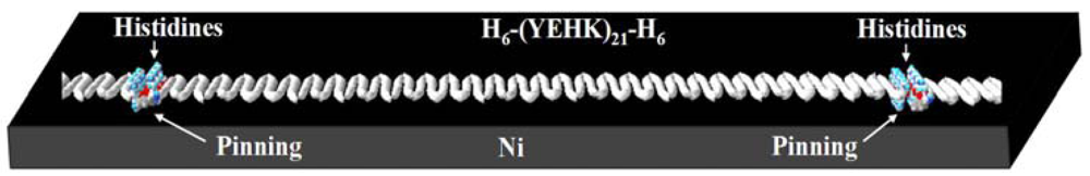
The force-scan adhesion data presented above can also shed some light on the configuration of the covalent bonding between the H6-(YEHK)x21-H6 fibrils and the Ni substrate. First, the AFM imaging data in Figures 3 and 4 indicate tip-induced ‘delayering’ of the bilayer H6-(YEHK)x21-H6 fibril. Bilayer fibrils are presumably formed via non-covalent hydrophobic interactions between the facially amphiphilic β-sheets [5]. Fibril formation results from His-His interactions between the individual polypeptides, and from the interaction along the histidine-tyrosine edges of the β-sheet polypeptides. The histidine-tyrosine edges are relatively hydrophobic amino acids compared to the relatively polar lysine-glutamic acid edges. Complete tip-induced delayering without displacing the β-sheets at the substrate interface, as observed in Figures 3 and 4, requires covalent bonding at multiple points along the fibril, if not at every hexahistidine group. This bonding configuration is schematically shown in Figure 9.
This bonding configuration is supported by force-scan imaging data for C6-(YEHK)x21-H6 fibrils. As shown in Figure 6, substantial deformation and reorientation of C6-(YEHK)x21-H6 fibrils on Au substrates was observed during forced scans with normal tip forces of 38 nN. Similar normal tip forces were insufficient to displace bonded H6-(YEHK)x21-H6 fibrils on Ni, although it was sufficient for fibril ‘delayering’ (Figures 2–4). The relative ease with which the AFM tip reoriented—but did not completely displace—the C6-(YEHK)x21-H6 fibrils on Au is consistent with cysteine-only substrate bonding.
To extract a more quantitative understanding of the relative adhesion measurements presented above between the polypeptide and MHA films, it is necessary to consider the relative interaction of the AFM tip with these materials. The forced-scan measurement methodology yielded a collective or average measure of molecular or nanostructural adhesion and not information specific to single bonding sites. The interaction volume between the tip and the polypeptide or MHA molecules depends on the tip-substrate contact area. The contact radius, a, of the tip under the range of applied normal tip forces has been estimated using the Hertz model for elastic deformation between sphere and plane: where F is the tip force, R is the tip radius, E is the Young's modulus of the relevant material, and n is the Poisson's ratio of the relevant material [25,26]. Based on a nominal tip radius of approximately 20 nm, the average contact radius between the tip and the substrate is approximately 2.5 nm for tip loads of approximately 100 nN on Ni or Au. The distance between two sulfur atoms in a dense packed MHA film is close to 0.6 nm [30]. The closest separation between two histidine nitrogen atoms or two cysteine sulfur atoms on polypeptide terminals is also of the order of 0.6 nm. Therefore, the number of Ni-N or S-Au bonds along the front half of the tip-substrate contact perimeter in the scan direction is likely to be approximately the same (∼12–15). Consequently, if the tip interacts with a single polypeptide-polypeptide link involving 12 histidines or cysteines, the normal tip force necessary to completely displace the polypeptide would, in principle, possess a similar magnitude to the normal tip force required to displace a region of a self-assembled MHA monolayer, presuming similar scan parameters. Therefore, the observation that similar tip forces were needed for complete removal of both MHA and C6-(YEHK)x21-H6 materials from the Au substrate implies collective and characteristic measurement of thiol-gold interactions. Now, noting that the histidine-Ni2+ binding energy is in the range of 67–128 kJ/mol [31] and the cysteine-Au (111) binding energy is in the range of 71–130 kJ/mol [29] similar normal tip forces would be expected to enable complete displace, in agreement with the data above.
3. Experimental Section
3.1. Polypeptide Synthesis and Structure
A block copolymer approach has been developed and reported by Topilina et al. [3] for the construction of DNA coding sequences for the expression and subsequent purification of polypeptides based on an alanine-glycine repeating backbone sequence incorporating sequential tyrosine (Y), glutamic acid (E), histidine (H), and lysine (K) beta-turn groups. The YEHK monomer unit of these polypeptides is {(AG)3YG(AG)3EG(AG)3HG(AG)3KG}. Based on this YEHK repeat structure, two distinct polypeptides were synthesized and purified for the work presented here. The first, denoted H6-(YEHK)x21-H6 consisted of 21 repeats of the YEHK structure with hexahistidine (H6) groups located at each terminus. The second, denoted C6-(YEHK)x21-H6, likewise consisted of 21 repeats of the YEHK structure with a hexahistidine group at one terminus and a hexacysteine group at the other. Previous studies have confirmed beta-sheet folding for H6-(YEHK)x21-H6 in addition to bilayer fibril formation [4-6].
3.2. Substrates and Polypeptide Deposition
Substrates used for polypeptide adhesion measurements included Ni, Au, silicon oxide, and highly-oriented pyrolytic graphite (HOPG). HOPG substrates consisted of 10 mm × 10 mm square, 1 mm thick pieces purchased from Veeco Instruments. Ni substrates consisted of a Ni (20nm)/Cr (5nm) stack deposited via e-beam deposition on a SiO2-coated Si wafer (200 mm diameter, (100) orientation). The Cr layer served to promote Ni adhesion to the SiO2. Au substrates were fabricated using a transfer technique. A 20 nm thick gold film was deposited on a mica substrate via e-beam evaporation. A section of a SiO2-coated Si wafer substrate was bonded to the Au film using cyanoacrylate adhesive and the mica was peeled off leaving an atomically-flat Au surface. SiO2 substrates consisted of 100 nm thick thermally-grown silicon oxide on 200 mm-diameter (100) p-type Si wafers (Silicon Quest International). All substrates were characterized using AFM. The average root-mean-square (RMS) surface roughness of the SiO2, Au, and HOPG samples was less than 0.2 ± 0.1 nm. The average RMS roughness of the Ni substrate was less than 0.4 ± 0.2 nm. Following synthesis, aqueous solutions of both polypeptide materials were prepared at a concentration of 0.12 mg/mL (determined using UV-visible spectroscopy) at a pH of 7.0 [1-3]. For polypeptide deposition 50 μL of the aqueous solution was dropped onto a given substrate via a micropipette and incubated at room temperature for 30 minutes to allow for polypeptide surface-directed assembly. The solution droplet was then removed by a micropipette and the surface was dried with a slow stream of nitrogen. AFM imaging and adhesion measurements commenced immediately after drying. Self-assembled monolayer films of 16-mercaptohexadecanoic acid (MHA) were deposited for purposes of comparison and calibration with polypeptide measurements on Au substrates due to its thiol-Au bonding. MHA was obtained from Aldrich. The mechanical strength of an individual thiol-Au interaction has been reported to be 1.4 ± 0.3 nN [27].
3.3. AFM ‘Forced-Scan’ Adhesion Measurements
Forced-scan adhesion measurements were carried out using a Veeco MultiMode AFM (Nanoscope IIIa controller) in contact imaging mode. Two different silicon nitride cantilevers were used: OTR4-35, (Veeco Instruments) with a spring constant of 0.08 N/m and tip radius is 15 nm; and NP-20, (Veeco Instruments) with a spring constant of 0.58 N/m and tip radius is 20 nm. The lower spring-constant cantilever was suitable for stable contact mode imaging of weakly adsorbed polypeptide materials. The higher spring-constant cantilever was used for scans of strongly bonded polypeptide or MHA materials requiring higher normal tip contact forces for adhesion measurement. The deflection sensitivity of the cantilever with spring constant 0.08 N/m was measured at 39.0 ± 3.0 nm/V. The deflection sensitivity of the cantilever with spring constant 0.58 N/m was 30.6 ± 1.8 nm/V.
‘Forced scans’ used relatively large normal tip contact forces. These scans alternated with ‘zero-force’ contact mode AFM scans to image molecular displacement of deformation due to prior ‘forced scans’. For zero-force contact mode scanning, the cantilever deflection setpoint was adjusted with the help of an acquired force curve to minimize the force between the cantilever tip and the sample to achieve a stable contact-mode image without polypeptide or MHA film deformation. The minimum force typically occurred for a negative set-point voltage between −0.3 volt and −0.1 volt consistent with a small (≤1 nN) overall attractive force between the tip and sample due to the presence of the water meniscus. For purposes of adhesion measurements, this minimum force is designated as a relative zero-point for the normal tip force and was referred to as a ‘zero-force’ scan throughout the present report.
Forced-scan adhesion measurements were carried out as described in what follows. For each polypeptide or MHA film adhesion evaluation, an initial zero-force AFM image is captured with a scan size of 2 μm. This step was followed by a series of 1 μm × 1 μm scans at successively larger normal tip contact forces until the molecular material is completely removed from the scan area. The deflection setpoint was typically increased in steps of 0.5 volt (corresponding to approximately 1.5 nN and 9 nN steps with 0.08 N/m and 0.58 N/m spring-constant cantilevers, respectively). After each scan at an increased setpoint, the sample region was re-imaged using zero-force scans to evaluate molecular deformation or displacement. All scanning was performed such that the fast scan direction was parallel to the long axis of the cantilever to minimize torsional tip deflection.
For each polypeptide or MHA sample, adhesion measurements were repeated at three different points. The errors in normal tip force calculation included errors in the measured deflection sensitivity and voltage setpoint. For all measurements the scan rate was kept constant at 2 μm/s in the fast scan direction and 3.9 nm/s in the slow scan direction. A single pair of cantilevers was used in all measurements without significant tip modification. Ni, Au, HOPG and SiO2 substrates without polypeptide or MHA showed no modification due to contact-mode AFM scanning over the tip-contact forces. The AFM images were flattened when necessary. No further image processing was performed.
It is worth noting that the total normal force in a contact mode AFM measurement in air includes the externally applied normal tip force and local adhesion forces from the adsorbed water meniscus force and tip-sample Van der Waals force [28-31]. Also, a lateral viscous force is present while scanning. Van der Waals forces are significant for smaller tip-sample separations (roughly 0.5–2 nm) and the meniscus force operates at tip-sample separations up to that required to break the meniscus (roughly 5–20 nm). In the forced-scan method adopted in the present measurements, the tip was kept in direct contact with the organic film or substrate. Hence, the Van der Waals force and normal tip force are believed to be dominant in the disruption of the polypeptide nanostructures. Since the Van der Waals force depends primarily on the tip radius and the separation, it can be assumed constant in all cases under investigation here. Therefore, measurement of the normal spring force required to displace the polypeptide materials or MHA from different substrates should provide a fairly accurate representation of the relative adhesion strength of molecular bonding to the substrate.
4. Conclusions
Employing an atomic force microscopy based forced scan methodology, the relative adhesion strength of histidine- and cysteine-tagged polypeptides was measured on HOPG, nickel, gold, and silicon oxide substrates. The forced scanning method has been used to reduce bilayer fibrils to monolayer fibrils without significantly modifying the fibril integrity or lateral displacement. In the case of histidine tagged polypeptide-based fibrils, the interaction between the histidine and nickel results in the pinning of the polypeptide fibrils at regular intervals of about 30 nm (length of each polypeptide molecule) along the fibril. The lack of end-end pinning is consistent with the poor mechanical stability of C6-(YEHK)x21-H6 polypeptide fibrils on gold [32]. In this case, the cysteine end of the polypeptide unit in the fibril binds strongly to the gold substrate but not the histidine end. His-tagged polypeptide nanostructures exhibited strong binding to nickel and weak binding to other inorganic surfaces including silicon oxide, HOPG and gold. The experiments provided a useful understanding regarding the adhesion of peptide-based nanofibrils to relevant substrate surfaces. This understanding is expected to be important for the demonstration of utility of these nanostructures for NEMS applications.
The findings above support the ability of the forced scan method to measure the relative adhesion strength of organic monolayers and nanostructures. The method does not represent an absolute measure of adhesion. Instead, it provides collective information for the polypeptide nanostructure adhesion to the substrates. However, employing the same method on a standard system such as thiol-gold can offer a correlation between the measured relative adhesion strengths to single binding events. A detailed study comprising the effect of parameters such as scan rate, scan area, surface coverage of molecular material, and tip radius, is required to further explore the characteristics and features of this method.


Acknowledgments
The authors acknowledge the support of the Interconnect Focus Center, one of five research centers funded under the Focus Center Research Program, a DARPA and Semiconductor Research Corporation program, as well as Focus Center-New York, under the New York State Foundation for Science, Technology and Innovation (NYSTAR).
References and Notes
- Bhushnan, B. Nanotribology and nanomechanics of MEMS/NEMS and BioMEMS/BioNEMS materials and devices. Micro. Eng. 2007, 84, 387–412. [Google Scholar]
- Arlett, J.; Paul, M.; Solomon, J.; Cross, M.; Fraser, S.; Roukes, M. BioNEMS: Nanomechanical Systems for Single-Molecule Biophysicsin. Proceedings of Controlled Nanoscale Motion in Biological and Artificial Systems (Nobel Symposium 131), Skåne, Sweden, 31 August 2005.
- Higashiya, S.; Ngo, S.C.; Bousman, K.S.; Jin, X.; Welch, J.T.; Cunningham, R.P.; Eisenbraun, E.T.; Geer, R.E.; Kaloyeros, A.E. Efficient biological construction of repetitive polypeptides for interconnect applications by block copolymerization. Ame. Chem. Soc. Div. Polymer Chem. 2003, 44, 679–680. [Google Scholar]
- Higashiya, S.; Ngo, S.C.; Bousman, K.S.; Welch, J.T.; Rana, N.; Carlsen, A.; Eisenbraun, E.; Geer, R.E.; Kaloyeros, A.E. Preparation and characterization of repetitive polypeptides for molecular interconnect applications. Polym. Mater. Sci. Eng. 2003, 89, 466–467. [Google Scholar]
- Topilina, N.I.; Higashiya, S.; Rana, N.; Ermolenkov, V.V.; Kossow, C.; Carlsen, A.; Ngo, S.C.; Wells, C.C.; Eisenbraun, E.T.; Dunn, K.; Lednev, I.K.; Geer, R.E.; Kaloyeros, A.E.; Welch, J.T. Bilayer fibril formation by genetically engineered polypeptides: Preparation and characterization. Biomacromolecules 2006, 7, 1104–1111. [Google Scholar]
- Scheibel, T.; Parthasarathy, R.; Sawicki, G.; Lin, X.M.; Jaeger, H.; Lindquist, S.L. Conducting nanowires built by controlled self-assembly of amyloid fibers and selective metal deposition. Proc. Natl. Acad. Sci. 2003, 100, 4527–4532. [Google Scholar]
- Rochefort, A.; Martel, R.; Avouris, P. Electrical switching in π-resonant 1D intermolecular Channels. Nano Lett. 2002, 2, 877–880. [Google Scholar]
- Stryer, L. Biochemistry, 4th ed.; W.H. Freeman and Company: New York, NY, USA, 1995. [Google Scholar]
- Marti, M.E.; Methivier, C; Dubot, P.; Pradier, C.M. Adsorption of (S)-histidine on Cu(110) and oxygen-covered Cu(110), a combined Fourier transform reflection absorption infrared spectroscopy and force field calculation study. J. Phys. Chem. B 2003, 107, 10785–10792. [Google Scholar]
- Crowe, J.; Döbeli, H.; Gentz, R.; Hochuli, E.; Stüber, D. Methods in Molecular Biology; Humana Press: Totowa, NJ, USA, 1994; Volume 31, pp. 371–387. [Google Scholar]
- Kröger, D.; Liley, M.; Schiweck, W.; Skerra, A.; Vogel, H. Immobilization of histidine-tagged proteins on gold surfaces using chelator thioalkanes. Biosens. Bioelectron. 1999, 14, 155–161. [Google Scholar]
- Soong, R.K.; Stelick, S.J.; Bachand, G.D.; Montemagno, C.D. Evaluating adhesion strength of biological molecules to nanofabricated substrates. Technical proceedings of the Second International Conference on Modeling and Simulation of Microsystems, San Juan, Puerto Rico, 1999; pp. 95–98.
- Bhushan, B. Principles and Applications of Tribology; Wiley: New York, NY, USA, 1999. [Google Scholar]
- Bhushan, B. Introduction to Tribology; Wiley: New York, NY, USA, 2002. [Google Scholar]
- Bhushan, B. Handbook of Micro/Nanotribology, 2nd ed.; CRC Press: Boca Raton, FL, USA, 1999. [Google Scholar]
- Schmitt, L.; Ludwig, M.; Gaub, H.E.; Tampe, R. A metal-chelating microscopy tip as a new toolbox for single-molecule experiments by atomic force microscopy. Biophys. J. 2000, 78, 3275–3285. [Google Scholar]
- Conti, M.; Falini, G.; Samori, B. How strong is the coordination bond between a histidine tag and Ni–nitrilotriacetate? An experiment of mechanochemistry on single molecules. Angew. Chem. Int. Ed. 2000, 112, 221–224. [Google Scholar]
- Lévy, R.; Maaloum, M. Specific molecular interactions by force spectroscopy: From single bonds to collective properties. Biophys. Chem. 2005, 117, 233–237. [Google Scholar]
- Keinberger, F.; Kada, G.; Gruber, H.J.; Pastushenko, V.P.; Schindler, H.; Hinterdorfer, P. Recognition force spectroscopy studies of the NTA-His6 bond. Single Mol. 2000, 1, 59–65. [Google Scholar]
- Sagvolden, G. Protein adhesion force dynamics and single adhesion events. Biophys. J. 1999, 77, 526–532. [Google Scholar]
- Sagvolden, G.; Giaever, I.; Feder, J. Manipulation force microscopy. Rev. Sci. Instrum. 1999, 70, 2769–2775. [Google Scholar]
- Sagvolden, G.; Giaever, I.; Pettersen, O.; Feder, J. Cell adhesion force microscopy. Proc. Natl. Acad. Sci. 1999, 96, 471–476. [Google Scholar]
- Sagvolden, G.; Giaever, I.; Feder, J. Characteristic protein adhesion forces on glass and polystyrene substrates by atomic force microscopy. Langmuir 1998, 14, 5984–5987. [Google Scholar]
- Samori, P. Scanning probe microscopies beyond imaging. J. Mater. Chem. 2004, 14, 1353–1366. [Google Scholar]
- Bhushan, B. Adhesion and stiction: mechanisms, measurement techniques and methods for reduction. J. Vac. Sci. Technol. B 2003, 21, 2262–2296. [Google Scholar]
- Ruan, J.A.; Bhushan, B. Atomic-scale friction measurements using friction force microscopy: Part II-Application to magnetic media. Trans. ASME 1994, 116, 378–388. [Google Scholar]
- Blackman, G.S.; Mate, C.M.; Philpott, M.R. Interaction forces of a sharp tungsten tip with molecular films on silicon surfaces. Phys. Rev. Lett. 1990, 65, 2270–2273. [Google Scholar]
- Burnham, N.A.; Colton, R.J. Measuring nanomechanical properties using an AFM. J. Vac. Sci. Technol. A 1989, 7, 2906–2913. [Google Scholar]
- Lahann, J.; Mitragotri, S.; Tran, T.N.; Kaido, H.; Sundaram, J.; Choi, I.S.; Hoffer, S.; Somorjai, G.A.; Langer, R. A reversibly switching surface. Science 2003, 299, 371–374. [Google Scholar]
- Geer, R. Encyclopedia of Nanoscience and Nanotechnology; Nalwa, H.S., Ed.; American Scientific Publishers: Stevenson Ranch, CA, USA, 2006; pp. 1–26. [Google Scholar]
- Johnson, K.L.; Kendall, K.; Roberts, A.D. Surface Energy and the Contact of Elastic Solids. Proceedings of the Royal Society of London, Series A, Mathematical and Physical Sciences, London, UK, 1971; 324, pp. 301–313.
- Felice, R.D.; Selloni, A.; Molinari, E. DFT Study of cysteine adsorption on Au(111). J. Phys. Chem. B 2003, 107, 1151–1156. [Google Scholar]
© 2011 by the authors; licensee MDPI, Basel, Switzerland. This article is an open access article distributed under the terms and conditions of the Creative Commons Attribution license (http://creativecommons.org/licenses/by/3.0/).
Share and Cite
Rana, N.; Kossow, C.; Eisenbraun, E.T.; Geer, R.E.; Kaloyeros, A.E. Controlling Interfacial Adhesion of Self-Assembled Polypeptide Fibrils for Novel Nanoelectromechanical System (NEMS) Applications. Micromachines 2011, 2, 1-16. https://doi.org/10.3390/mi2010001
Rana N, Kossow C, Eisenbraun ET, Geer RE, Kaloyeros AE. Controlling Interfacial Adhesion of Self-Assembled Polypeptide Fibrils for Novel Nanoelectromechanical System (NEMS) Applications. Micromachines. 2011; 2(1):1-16. https://doi.org/10.3390/mi2010001
Chicago/Turabian StyleRana, Narender, Christopher Kossow, Eric T. Eisenbraun, Robert E. Geer, and Alain E. Kaloyeros. 2011. "Controlling Interfacial Adhesion of Self-Assembled Polypeptide Fibrils for Novel Nanoelectromechanical System (NEMS) Applications" Micromachines 2, no. 1: 1-16. https://doi.org/10.3390/mi2010001