
A Micro Saddle Coil with Switchable Sensitivity for Local High-Resolution Imaging of Luminal Tissue †

Abstract
:
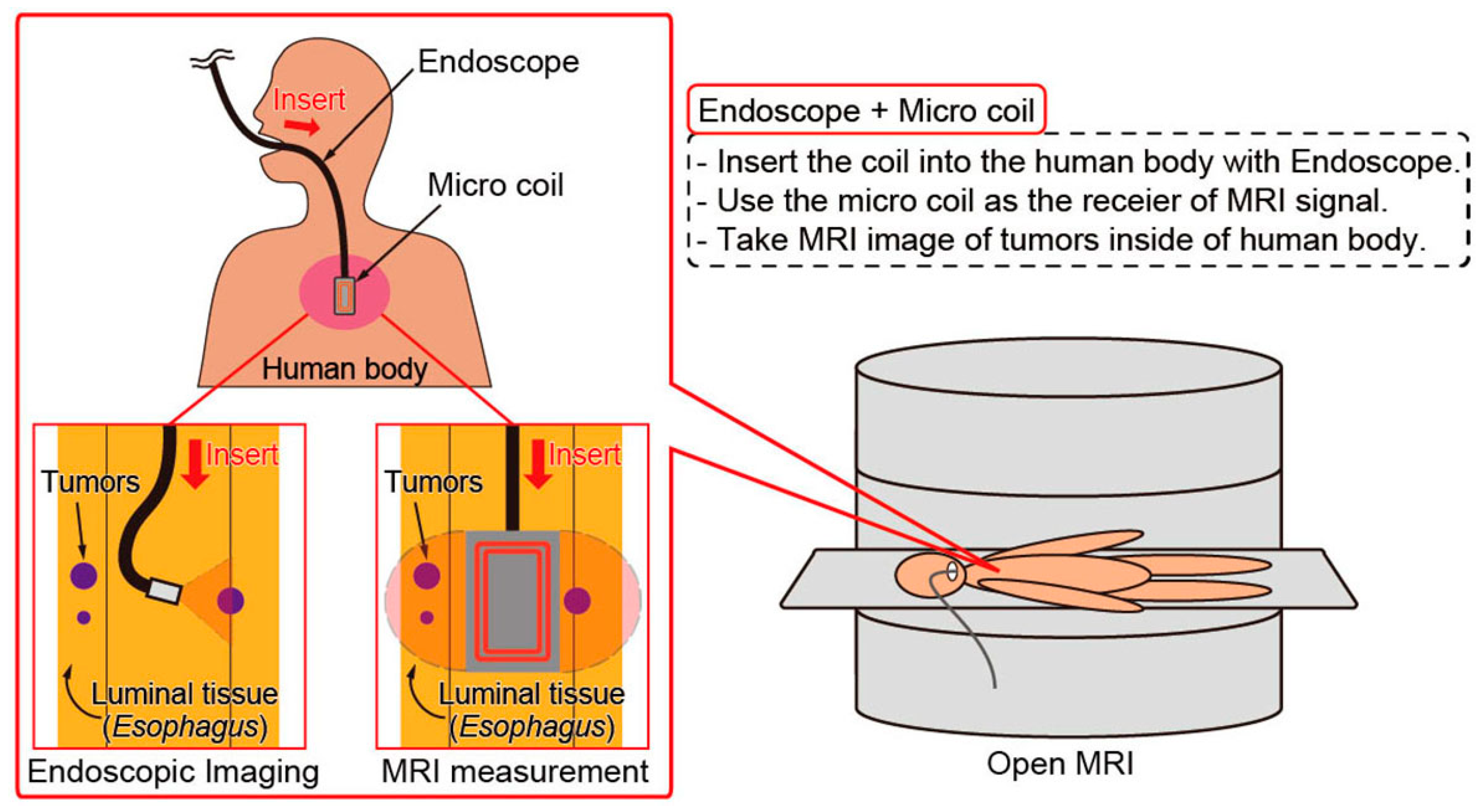
1. Introduction
2. Concept and Fabrication
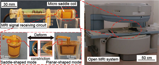
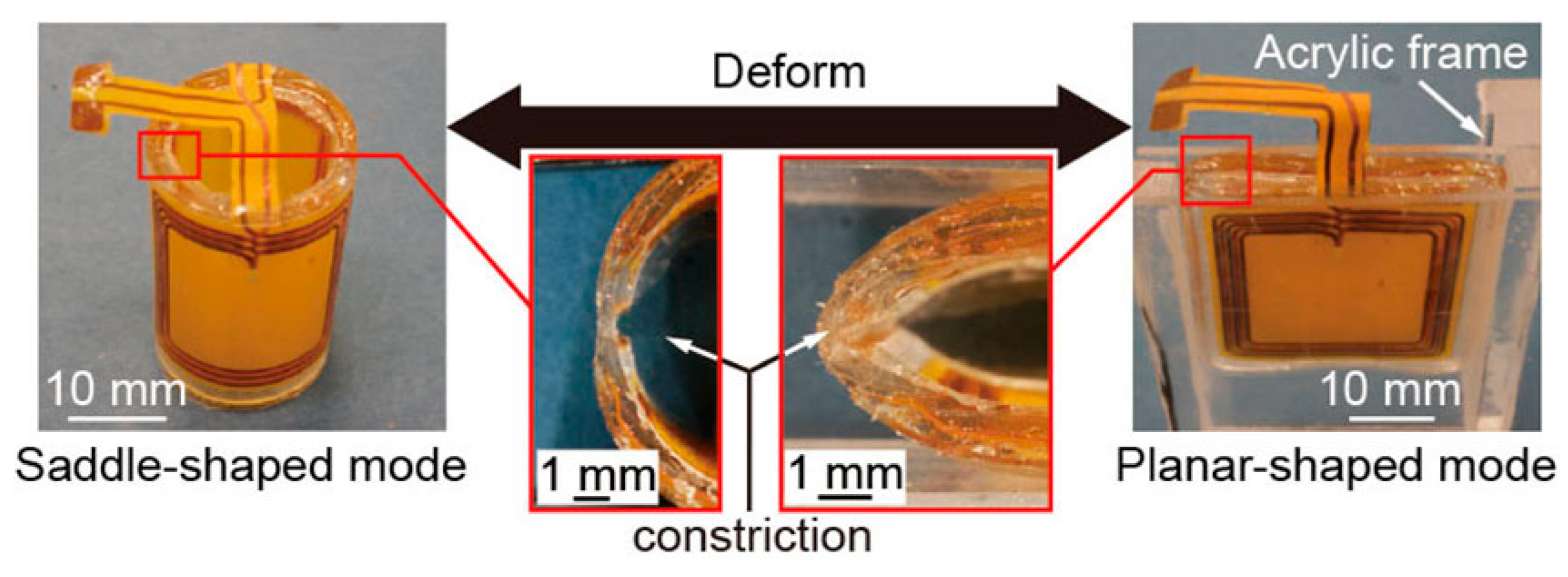
2.1. Concept of the Micro Saddle Coil
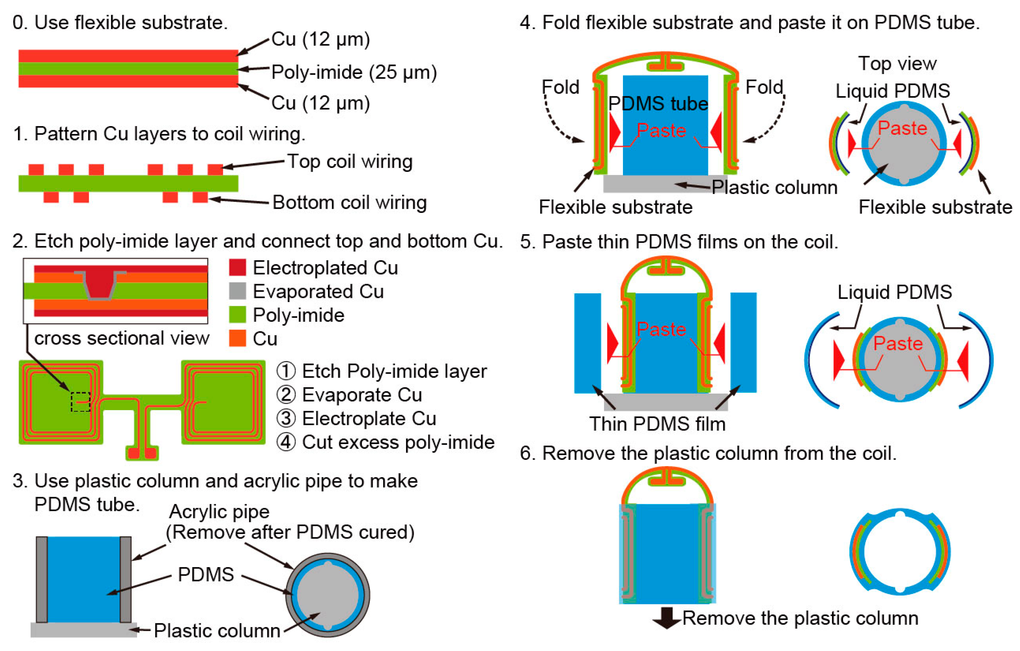
2.2. Fabrication Process
3. Experiment
3.1. Electrical Characteristics of the Coil
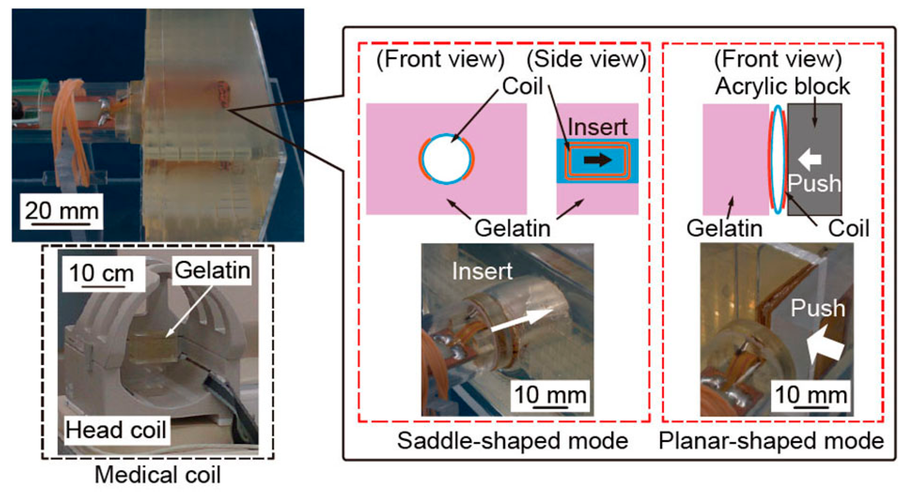
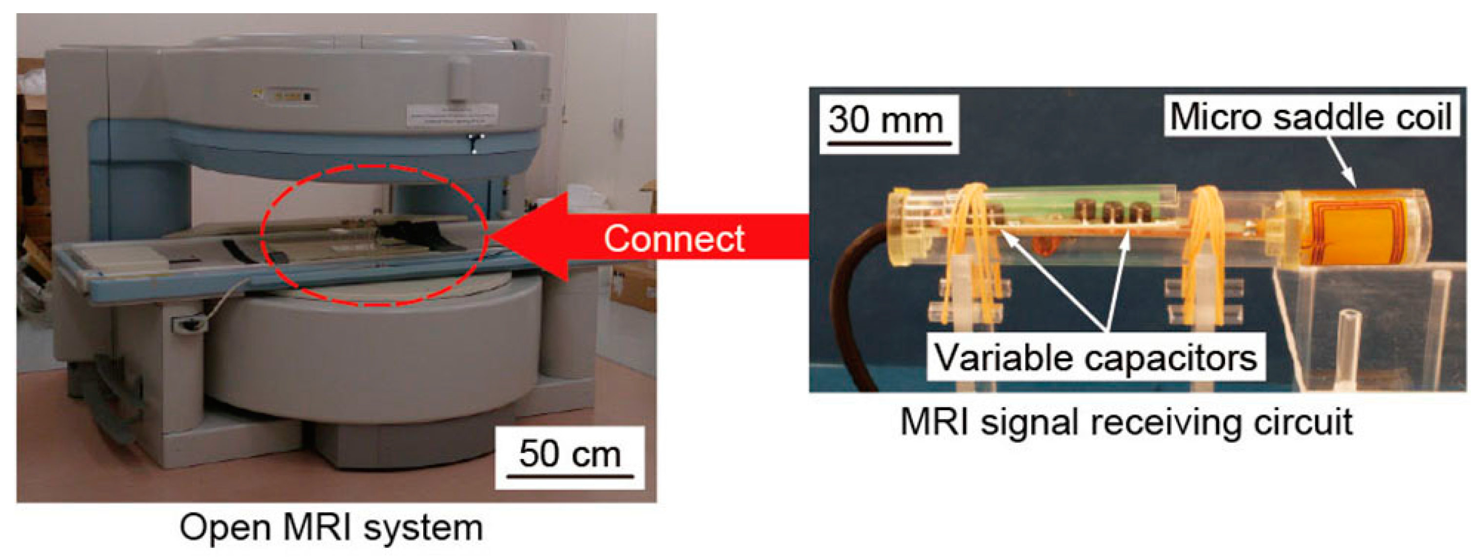
3.2. Experimental Setup for Taking MRI Images
3.3. SNR Measuring Experiment
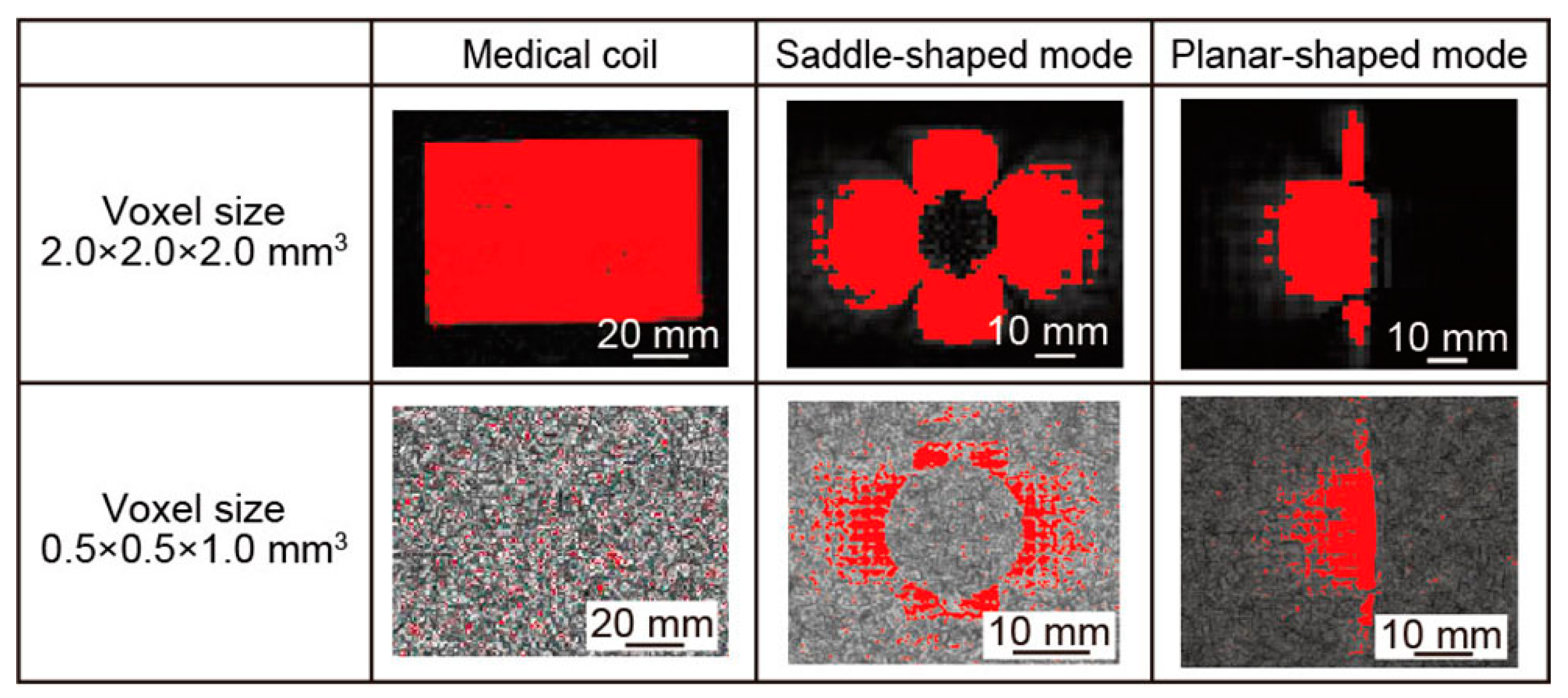
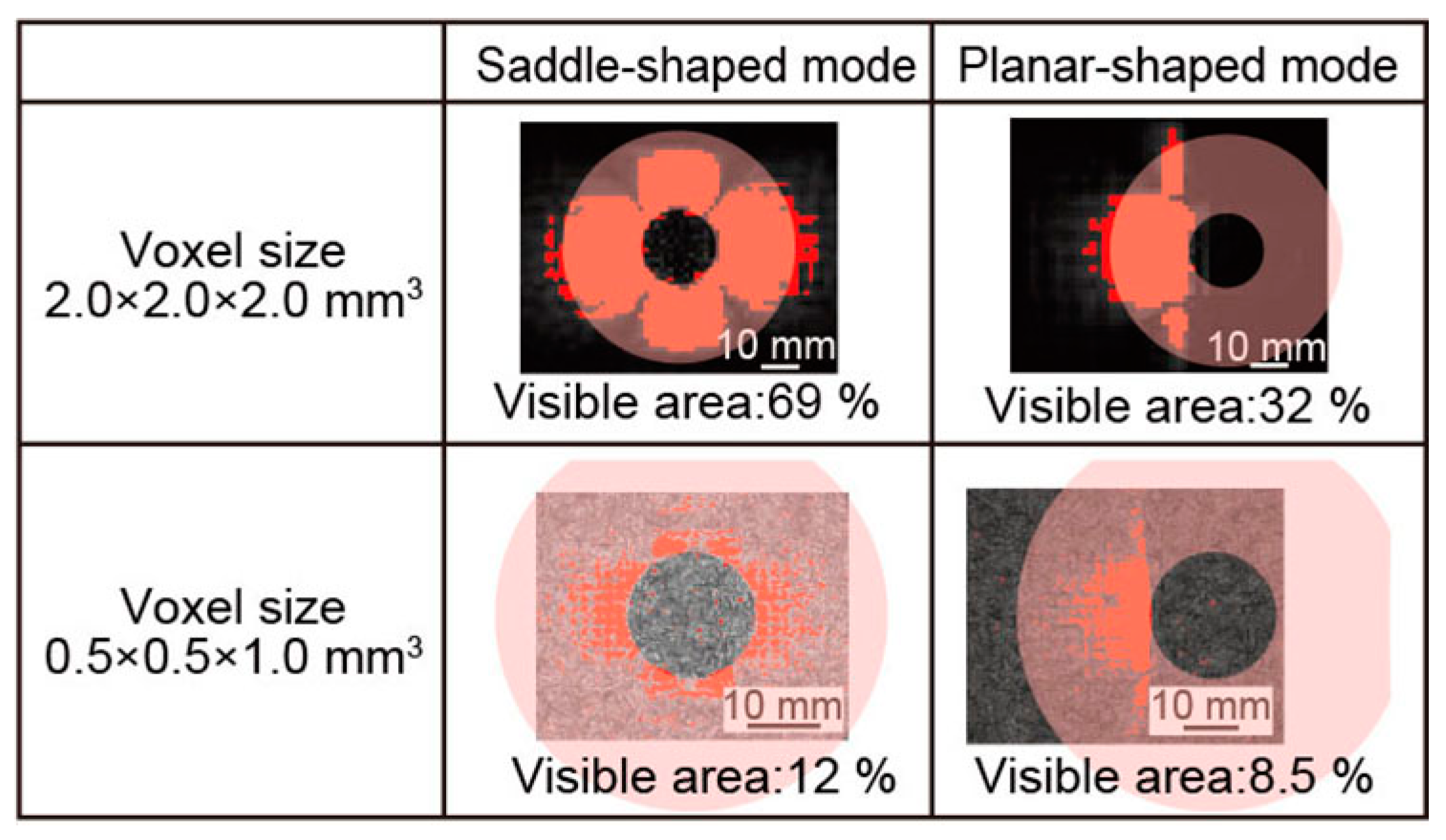
3.4. Visible Area Measuring Experiment
4. Discussion
4.1. SNR Improvement of the MRI Images Taken by Micro Saddle Coil
4.2. Comparison of Visible Area of MRI Images
5. Conclusions
Acknowledgments
Author Contributions
Conflicts of Interest
References
- Black, P.M.; Moriarty, T.; Alexander, E.; Stieg, P.; Woodard, E.J.; Gleason, P.L.; Martin, C.H.; Kikinis, R.; Schwartz, R.B.; Jolesz, F.A. Development and implementation of intraoperative magnetic resonance imaging and its neurosurgical applications. Neurosurgery 1997, 41, 831–845. [Google Scholar] [CrossRef] [PubMed]
- Iseki, H.; Muragaki, Y.; Nakamura, R.; Ozawa, N.; Tabuguchi, H.; Hori, T.; Takakura, K. Intelligent operation theater using intraoperative open-MRI. Magn. Reson. Med. Sci. 2005, 4, 129–136. [Google Scholar] [CrossRef] [PubMed]
- Wirtz, C.R.; Bonsanto, M.M.; Knauth, M.; Tronnier, V.M.; Albert, F.K.; Staubert, A.; Kunze, S. Intraoperative magnetic resonance imaging to update interactive navigation in neurosurgery: Method and preliminary experience. Comput. Aided Surg. 1997, 2, 172–179. [Google Scholar] [CrossRef] [PubMed]
- Inui, K.; Nakazawa, J.; Yoshino, J.; Ukai, H. Endoscopic MRI. Pancreas 1998, 16, 413–417. [Google Scholar] [CrossRef] [PubMed]
- Umakant, R.D.; Andreanna, D.W.; Jason, A.W.; Zahir, A.; David, J.G.; David, J.L.; Mark, R.T.; Simon, D.T.; Nandita, M.S. Esopageal cancer staging with endoscopic MR imaging: Pilot study. Radiology 2004, 230, 281–286. [Google Scholar]
- Goto, S.; Matsuoka, T.; Kuroda, K.; Esashi, M.; Haga, Y. Development of High-Resolution Intraluminal and Intravascular MRI Probe Using Microfabrication on Cylindrical Substrates. In Proceedings of IEEE 20th International Conference on Micro Electro Mechanical Systems (MEMS 2007), Kobe, Japan, 21–25 January 2007; pp. 329–332.
- Murashige, K.; Dohi, T. The micro saddle coil with switchable sensitivity for magnetic resonance imaging. In Proceedings of IEEE 28th International Conference on Micro Electro Mechanical Systems (MEMS 2015), Estoril, Portugal, 18–22 January 2015; pp. 674–677.
- Takahishi, H.; Dohi, T.; Matsumoto, K.; Shimoyama, I. A micro planar coil for local high resolution magnetic resonance imaging. In Proceedings of IEEE 20th International Conference on Micro Electro Mechanical Systems (MEMS 2007), Kobe, Japan, 21–25 January 2007; pp. 549–552.
- Massin, C.; Vincent, F.; Homsy, A.; Ehrmann, K.; Boero, G.; Besse, P.A.; Daridon, A.; Verpoorte, E.; Rooji, N.F.; Popovic, R.S. Planar microcoil-based microfluidic NMR probes. J. Magn. Reson. 2003, 164, 242–245. [Google Scholar] [CrossRef]
- Massin, C.; Eroglu, S.; Vincent, F.; Gimi, B.S.; Besse, P.A.; Magin, R.L.; Popovic, R.S. Planar microcoil-based magnetic resonance imaging of cell. In Proceedings of IEEE 12th International Conference on Solid-State Senseors, Actuators and Microsystems (Transducers 2003), Boston, MA, USA, 8–12 June 2003; pp. 967–970.
- Renaud, L.; Armenean, M.; Berry, L.; Kleimann, P.; Morin, P.; Pitaval, M.; O’Brien, J.; Brunet, M.; Saint-Jalmes, H. Implantable planar rf microcoils for NMR microspectroscopy. Sens. Actuators A Phys. 2002, 99, 244–248. [Google Scholar] [CrossRef]
- Meier, R.C.; Hofflin, J.; Badilita, V.; Wallrabe, U.; Korvink, J.G. Microfluidic integration of wirebonded microcoils for on-chip applications in nuclear magnetic resonance. J. Micromech. Microeng. 2014, 24, 244–248. [Google Scholar] [CrossRef]
- Dohi, T.; Kuwana, K.; Matsumoto, K.; Shimoyama, I. A standing micro coil for a high resolution MRI. In Proceedings of IEEE 14th International Conference on Solid-State Sensors, Actuators and Microsystems (Transducers 2007), Lyon, France, 10–14 June 2007; pp. 1313–1315.
- Inamura, T.; Dohi, T. Cone-shaped micro coil for magnetic resonance imaging. In Proceedings of IEEE IEEE 26th International Conference on Micro Electro Mechanical Systems (MEMS 2013), Taipei, Taiwan, 20–24 January 2013; pp. 335–338.
- Hoult, D.I.; Richards, R.E. The signal to noise ratio of the nuclear magnetic resonance. J. Magn. Reson. 1976, 24, 71–85. [Google Scholar] [CrossRef]
- David, J.; Andreanna, D.W.; Umakant, D.; Nandita, M.S. An inductively-coupled, detachable receiver coil system for use with magnetic resonance compatible endoscope. J. Magn. Reson. Imaging 2003, 18, 131–135. [Google Scholar]
- Syms, R.R.A.; Young, I.R.; Wadsworth, C.A.; Taylor-Robinson, S.D.; Rea, M. Magnetic Resonance Imaging Duodenoscope. IEEE Trans. Biomed. Eng. 2013, 60, 3458–3467. [Google Scholar] [CrossRef] [PubMed]
- Ginsberg, D.M.; Melchner, M.J. Optimum Geometry of Saddle Shaped Coils for Generating a Uniform Magnetic Field. Rev. Sci. Instrum. 1970, 42, 122–123. [Google Scholar] [CrossRef]
- Syms, R.R.A.; Floume, T.; Young, I.R.; Solymar, L.; Rea, M. Flexible magnetoinductive ring MRI detector: Design for invariant nearest neighbour coupling. Metamaterials 2010, 4, 1–14. [Google Scholar] [CrossRef]


| Coil Shape | Saddle-Shaped Mode | Planar-Shaped Mode |
|---|---|---|
| Inductance (μH) | 2.45 | 3.07 |
| Resistance (Ω) | 3.31 | 3.92 |
| Q-factor (–) | 39.9 | 42.9 |
| Self-resonant frequency (MHz) | 44.8 | 39.5 |
| Voxel Size | SNRs of MRI Images | Increase Rate from Saddle-Shape to Planar-Shape | ||
|---|---|---|---|---|
| Medical Head Coil | Saddle-Shaped Mode | Planar-Shaped Mode | ||
| 2.0 × 2.0 × 2.0 (mm3) | 41.7 | 194.9 | 505.9 | 259% |
| 0.5 × 0.5 × 1.0 (mm3) | 3.5 | 11.7 | 37.4 | 319% |
| Voxel Size | Medical Head Coil | Saddle-Shaped Mode | Planar-Shaped Mode |
|---|---|---|---|
| 2.0 × 2.0 × 2.0 (mm3) | 37,268 mm2 | 5188 mm2 | 1196 mm2 |
| 0.5 × 0.5 × 1.0 (mm3) | 41.5 mm2 | 987.5 mm2 | 320.3 mm2 |
© 2016 by the authors. Licensee MDPI, Basel, Switzerland. This article is an open access article distributed under the terms and conditions of the Creative Commons by Attribution (CC-BY) license ( http://creativecommons.org/licenses/by/4.0/).
Share and Cite
Dohi, T.; Murashige, K. A Micro Saddle Coil with Switchable Sensitivity for Local High-Resolution Imaging of Luminal Tissue. Micromachines 2016, 7, 67. https://doi.org/10.3390/mi7040067
Dohi T, Murashige K. A Micro Saddle Coil with Switchable Sensitivity for Local High-Resolution Imaging of Luminal Tissue. Micromachines. 2016; 7(4):67. https://doi.org/10.3390/mi7040067
Chicago/Turabian StyleDohi, Tetsuji, and Kousuke Murashige. 2016. "A Micro Saddle Coil with Switchable Sensitivity for Local High-Resolution Imaging of Luminal Tissue" Micromachines 7, no. 4: 67. https://doi.org/10.3390/mi7040067