Analytical, Numerical and Experimental Study of a Horizontal Electrothermal MEMS Microgripper for the Deformability Characterisation of Human Red Blood Cells


Abstract
:1. Introduction
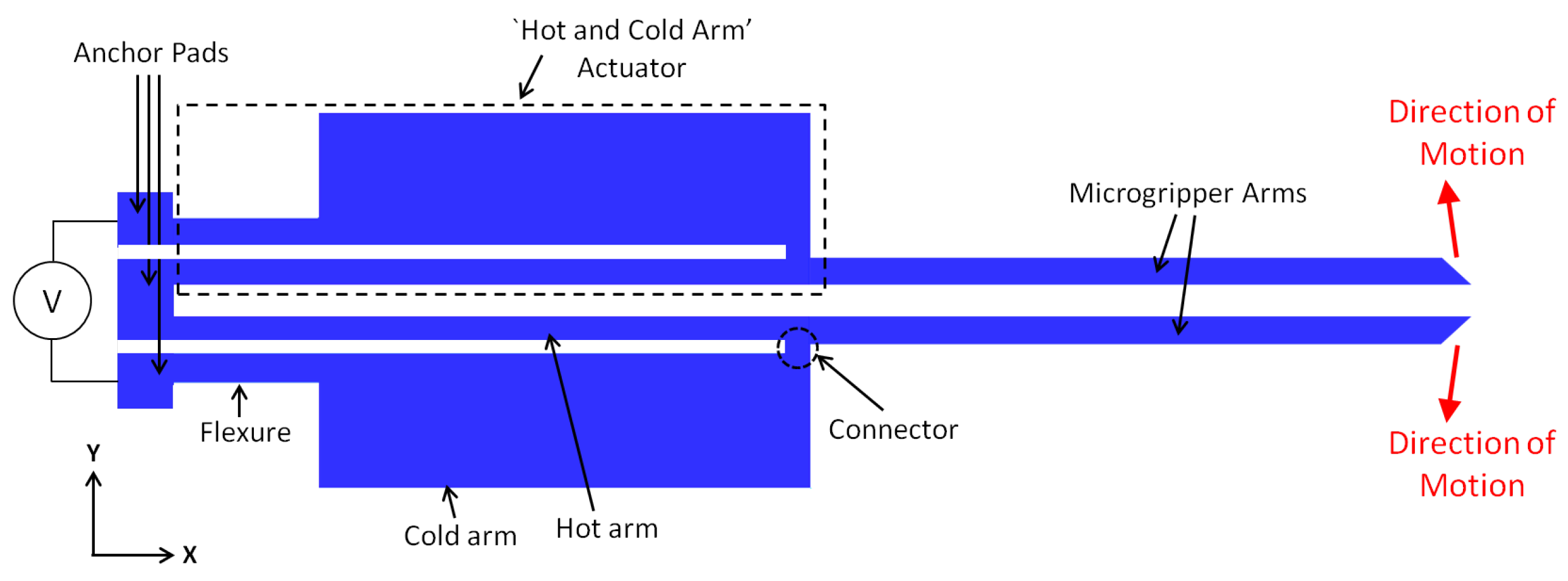
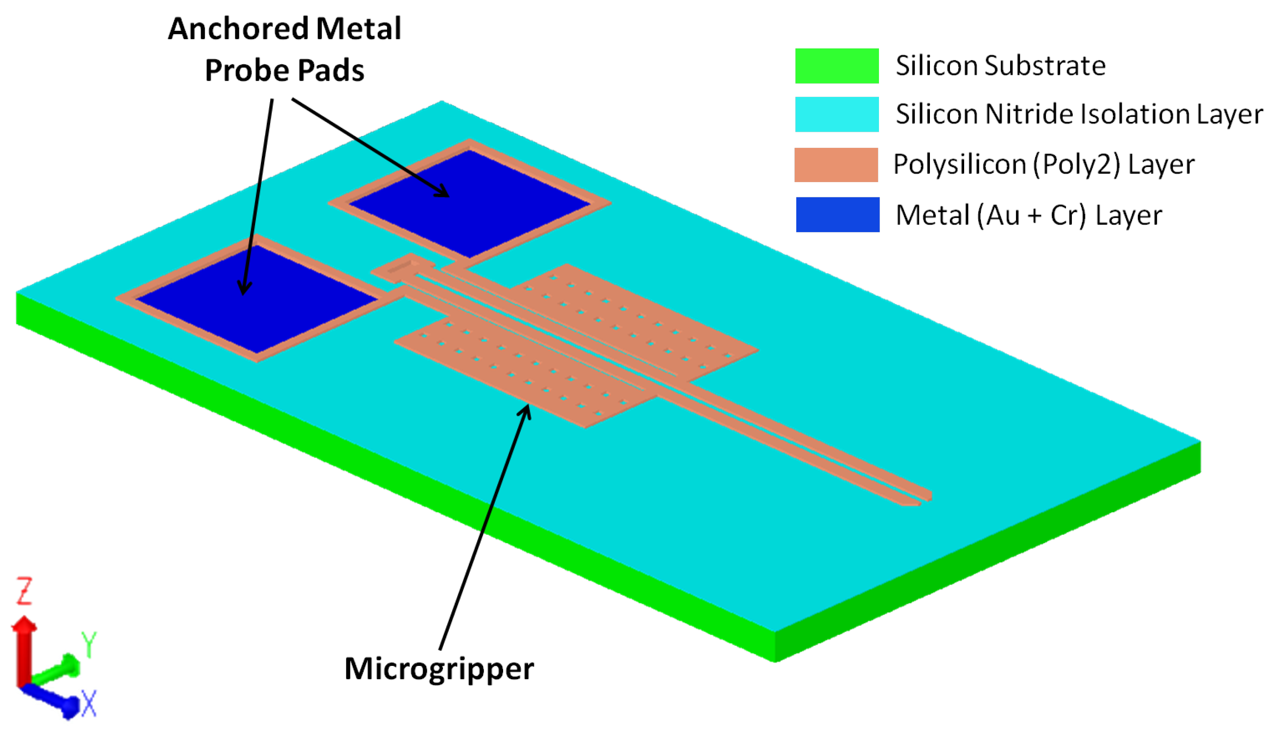
2. Microgripper Design and Operating Principle
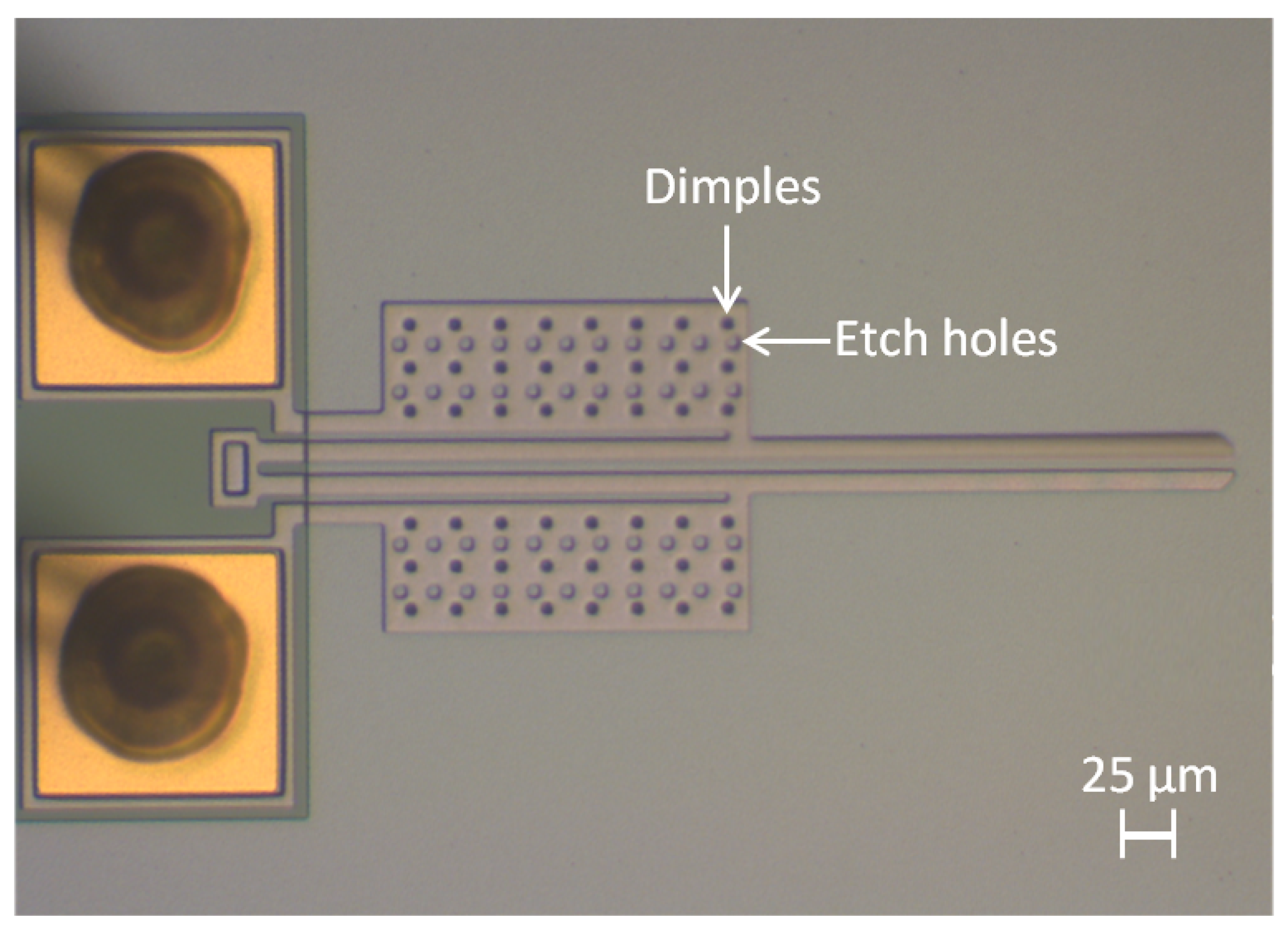
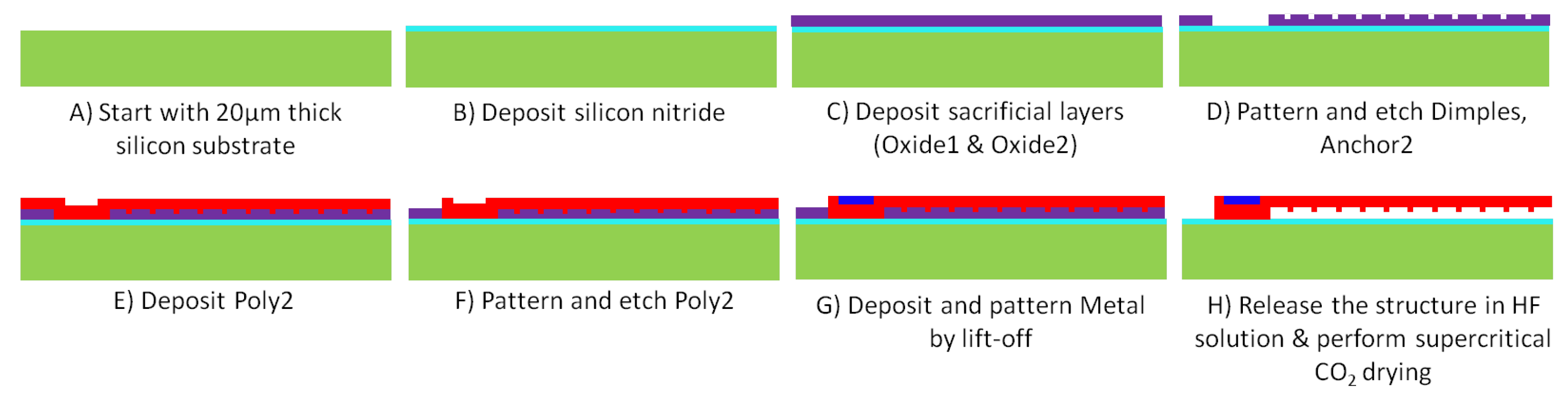
3. Fabrication Process
4. Analytical Model
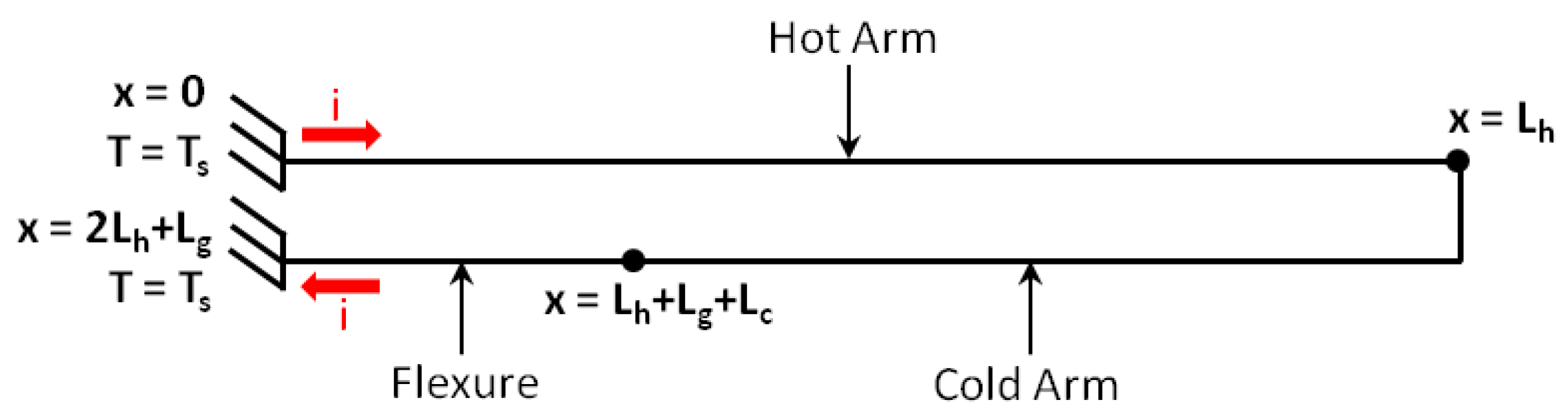
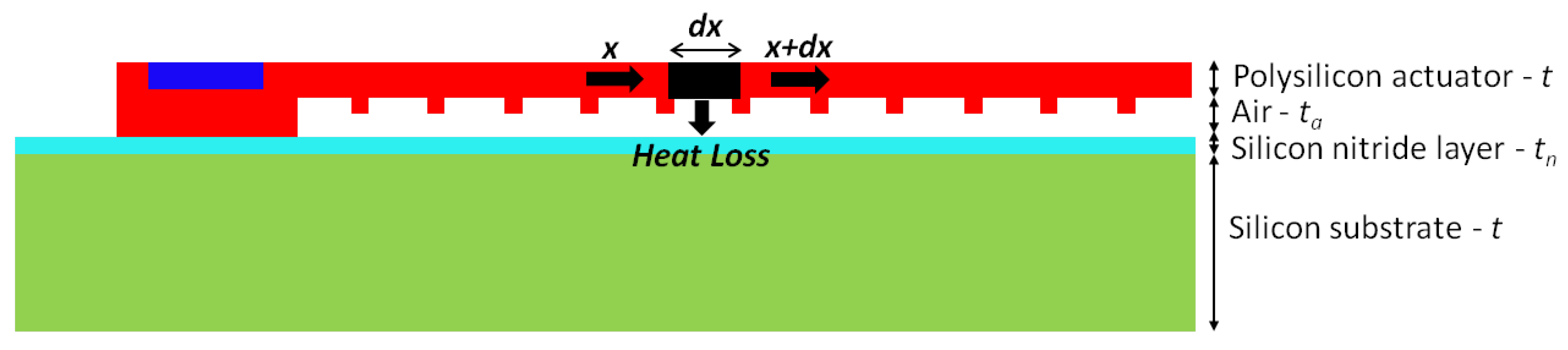
4.1. One-Dimensional Model
4.2. Electrothermal Analysis
- At =
- At , =
- At ++, =
- At +, =
- At , =
- At ++, =
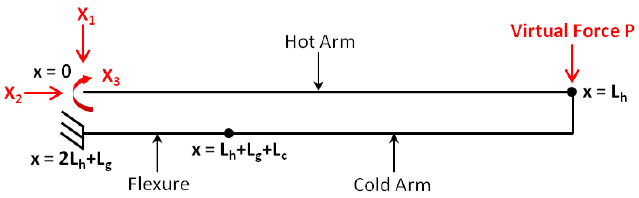
4.3. Thermomechanical Analysis
5. Numerical Model
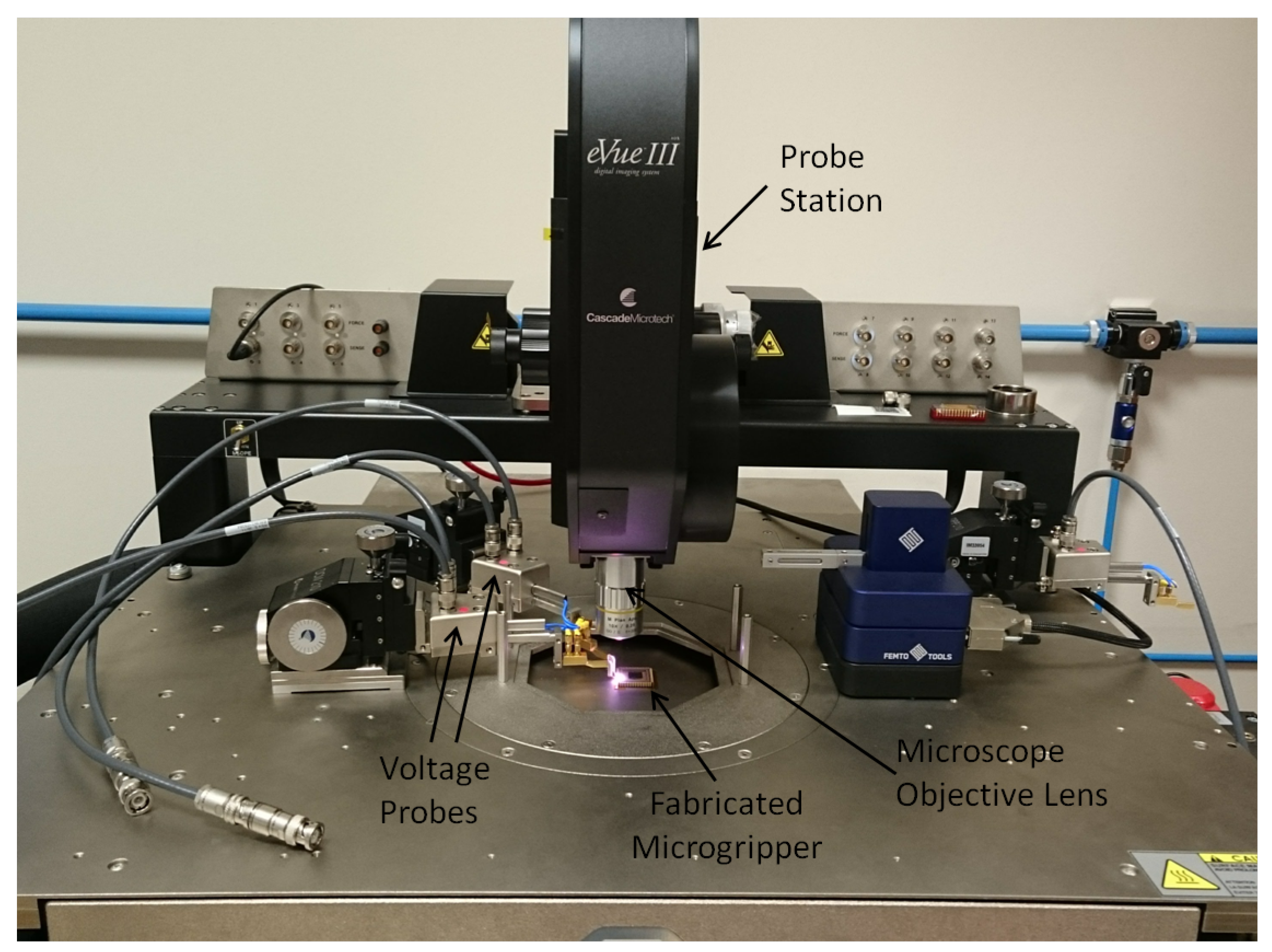
6. Experimental Setup
7. Results
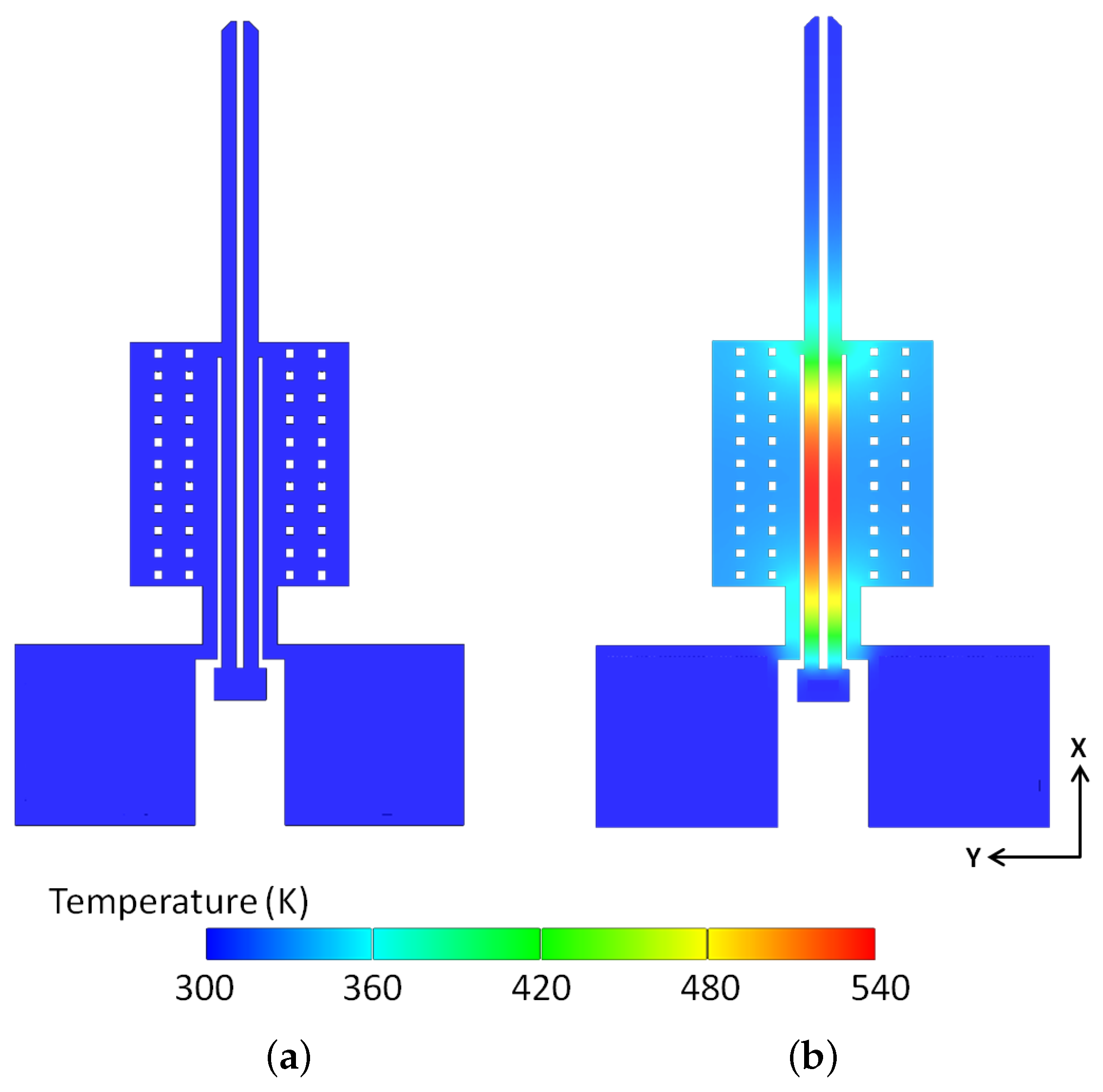
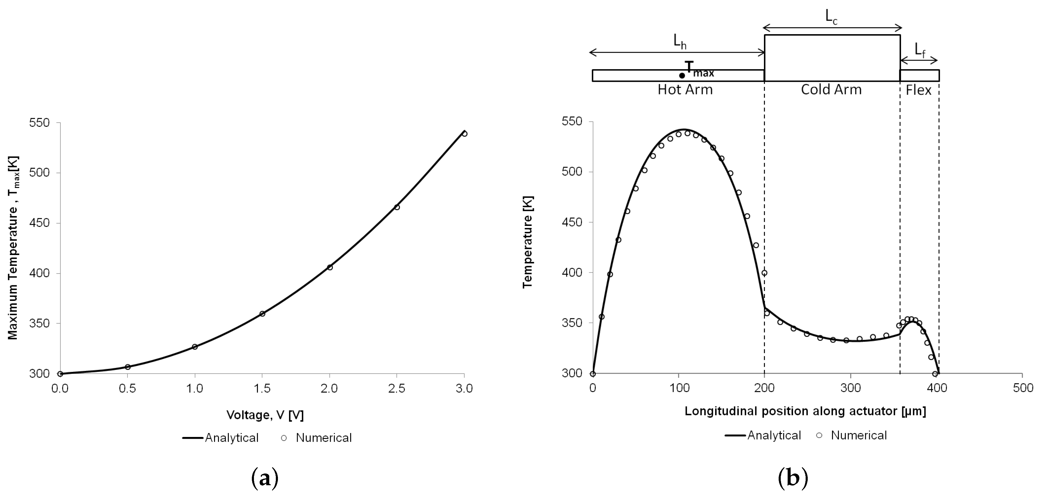
7.1. Thermal Analysis
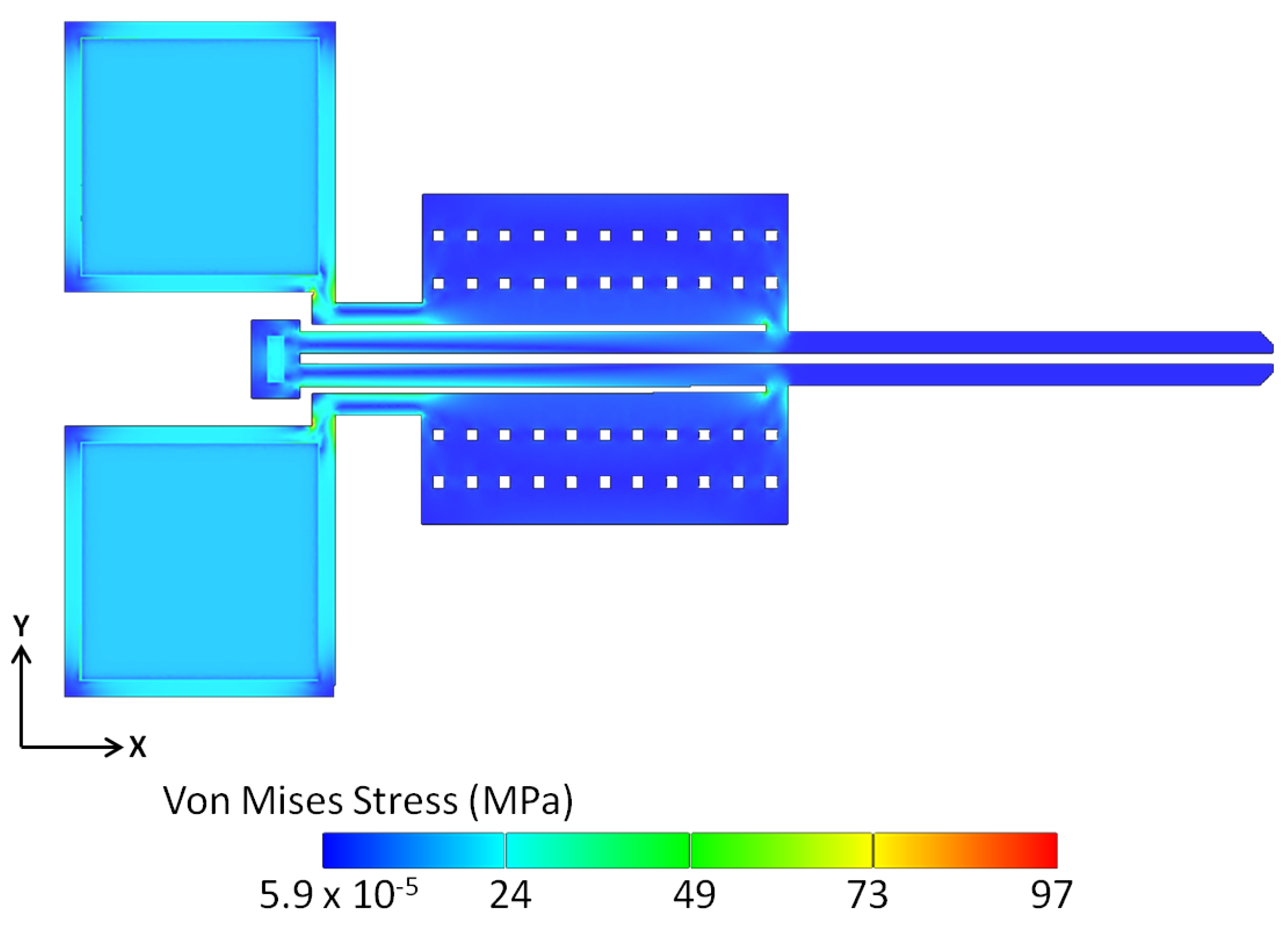
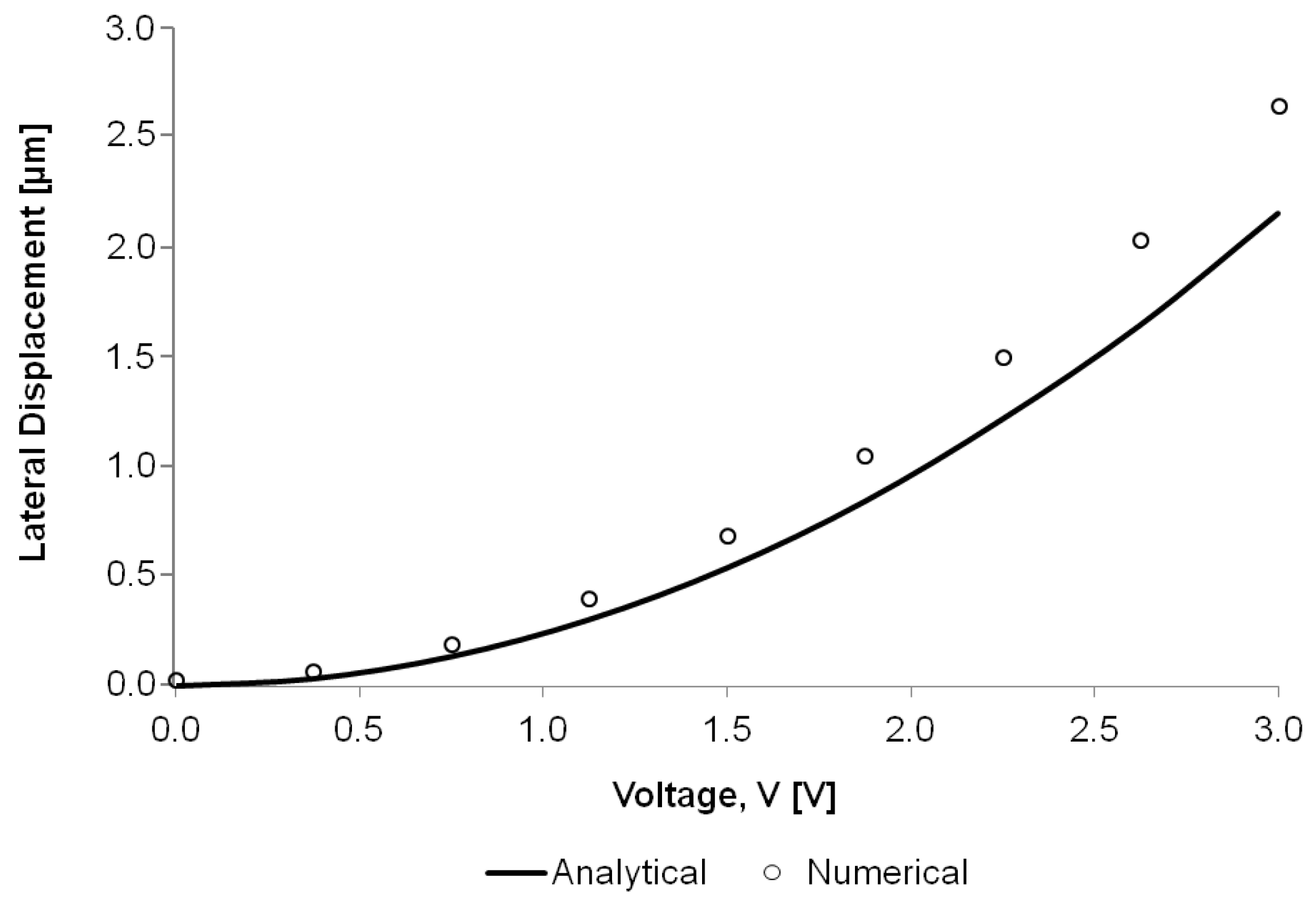
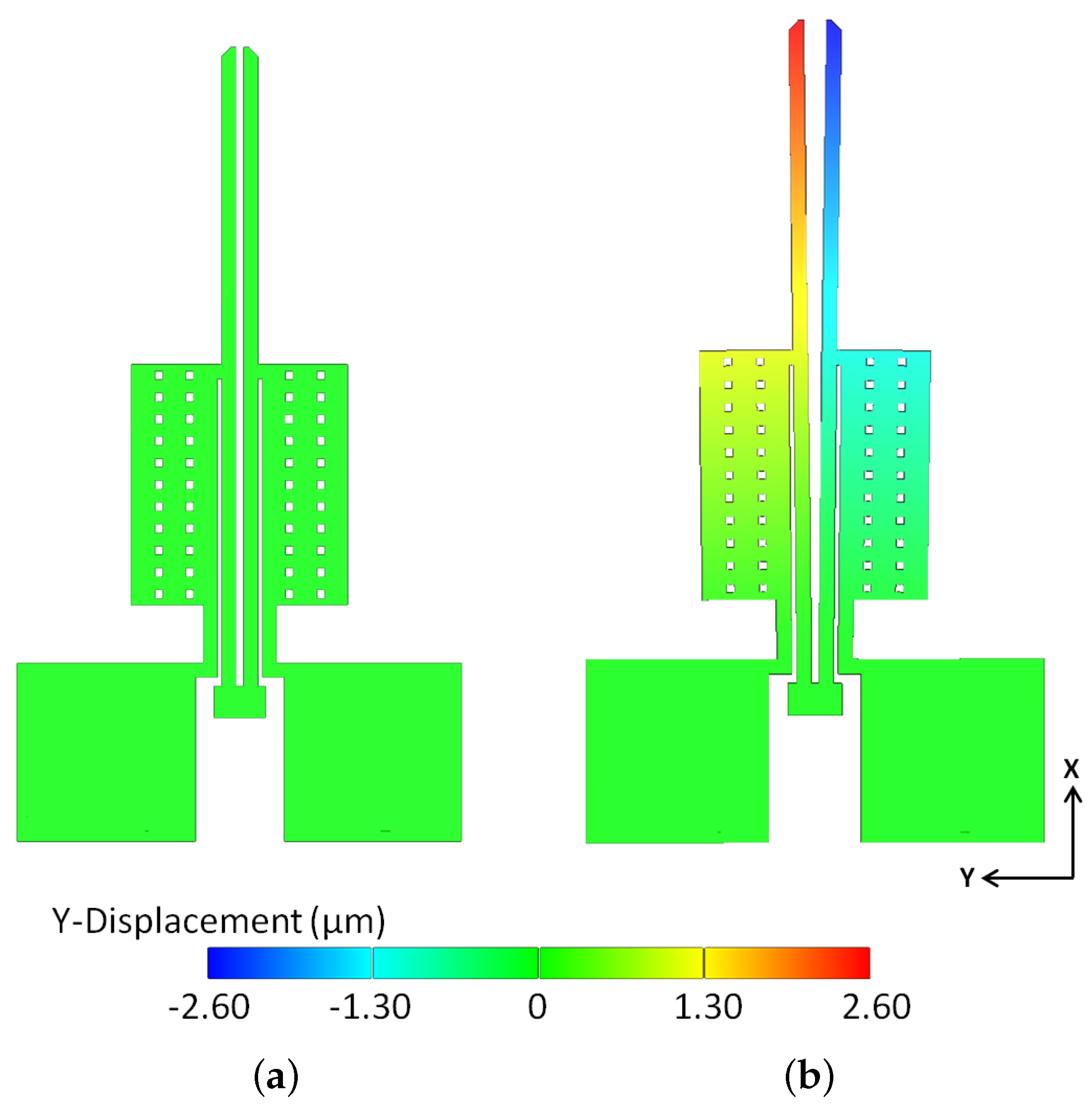
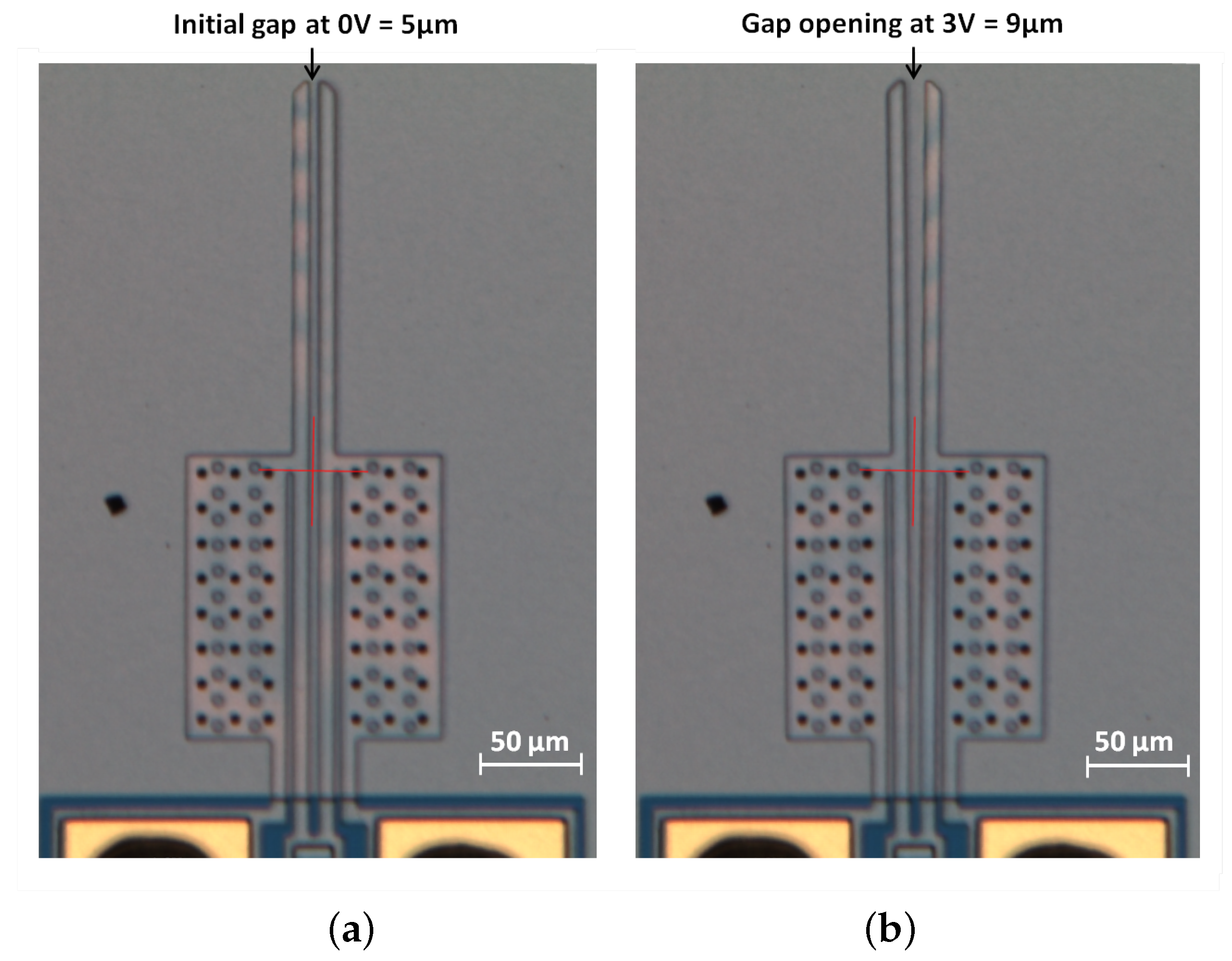
7.2. Structural Analysis
8. Conclusions
Acknowledgments
Author Contributions
Conflicts of Interest
References
- Ivanova, K.; Ivanov, T.; Badar, A.; Volland, B.E.; Rangelow, I.W.; Andrijasevic, D.; Sümecz, F.; Fischer, S.; Spitzbart, M.; Brenner, W.; et al. Thermally driven microgripper as a tool for micro assembly. Microelectron. Eng. 2006, 83, 1393–1395. [Google Scholar] [CrossRef]
- Zhang, Y.; Chen, B.K.; Liu, X.; Sun, Y. Autonomous robotic pick-and-place of microobjects. IEEE Trans. Robot. 2010, 26, 200–207. [Google Scholar] [CrossRef]
- Zhang, R.; Chu, J.; Wang, H.; Chen, Z. A multipurpose electrothermal microgripper for biological micro-manipulation. Microsyst. Tech. 2013, 19, 89–97. [Google Scholar] [CrossRef]
- Verotti, M.; Dochshanov, A.; Belfiore, N.P. A comprehensive survey on microgrippers design: Mechanical structure. J. Mech. Des. 2017, 139, 060801. [Google Scholar] [CrossRef]
- Dochshanov, A.; Verotti, M.; Belfiore, N.P. A comprehensive survey on microgrippers design: Operational strategy. J. Mech. Des. 2017, 139, 070801. [Google Scholar] [CrossRef]
- Nguyen, N.-T.; Ho, S.-S.; Low, C.L. A polymeric microgripper with integrated thermal actuators. J. Microelectromech. Syst. 2004, 14, 969–974. [Google Scholar] [CrossRef]
- Kim, C.-J.; Pisano, A.P.; Muller, R.S. Silicon-processed overhanging microgripper. J. Microelectromech. Syst. 1992, 1, 31–36. [Google Scholar] [CrossRef]
- Bagolini, A.; Ronchin, S.; Bellutti, P.; Chistè, M.; Verotti, M.; Belfiore, N.P. Fabrication of novel MEMS microgrippers by deep reactive ion etching with metal hard mask. J. Microelectromech. Syst. 2017, 26, 7920329. [Google Scholar] [CrossRef]
- Wierzbicki, R.; Houston, K.; Heerlein, H.; Barth, W.; Debski, T.; Eisinberg, A.; Menciassi, A.; Carrozza, M.C.; Dario, P. Design and fabrication of an electrostatically driven microgripper for blood vessel manipulation. Microelectron. Eng. 2006, 83, 1651–1654. [Google Scholar] [CrossRef]
- Xu, Q. Design, Fabrication, and testing of an MEMS microgripper with dual-axis force sensor. IEEE Sens. J. 2015, 15, 7150331. [Google Scholar] [CrossRef]
- Chronis, N.; Lee, L.P. Electrothermally activated SU-8 microgripper for single cell manipulation in solution. J. Microelectromech. Syst. 2005, 14, 857–863. [Google Scholar] [CrossRef]
- Jia, Y.; Xu, Q. MEMS microgripper actuators and sensors: The state-of-the-art survey. Recent Patents Mech. Eng. 2013, 6, 132–142. [Google Scholar] [CrossRef]
- Guckel, H.; Klein, J.; Chtistenson, T.; Skrobis, K.; Laudon, M.; Lovell, E. Thermo-magnetic Metal Flexure Actuators. In Proceedings of the Technical Digest, Solid State Sensors and Actuators Workshop, Hilton Head, SC, USA, 13–16 June 1992; pp. 73–75. [Google Scholar]
- Comtois, J.H.; Bright, V.M. Surface micromachined polysilicon thermal actuator arrays and applications. Proceedings of Solid-State Sensors and Actuators Workshop, Hilton Head Island, SC, USA, 3–6 June 1996; pp. 174–177. [Google Scholar]
- Yang, S.; Xu, Q. A review on actuation and sensing techniques for MEMS-based microgrippers. J. Micro-Bio Robot. 2017, 13, 1–14. [Google Scholar] [CrossRef]
- Verotti, M.; Dochshanov, A.; Belfiore, N.P. Compliance synthesis of CSFH MEMS-based microgrippers. J. Mech. Des. Trans. ASME 2017, 139, 022301. [Google Scholar] [CrossRef]
- Di Giamberardino, P.; Bagolini, A.; Bellutti, P.; Rudas, I.J.; Verotti, M.; Botta, F.; Belfiore, N.P. New MEMS tweezers for the viscoelastic characterization of soft materials at the microscale. Micromachines 2017, 9, 15. [Google Scholar] [CrossRef]
- Kim, K.; Liu, X.; Zhang, Y.; Sun, Y. Nanonewton force-controlled manipulation of biological cells using a monolithic MEMS microgripper with two-axis force feedback. J. Micromech. Microeng. 2008, 18, 055013. [Google Scholar] [CrossRef]
- Kim, K.; Liu, X.; Zhang, Y.; Cheng, J.; Yu, W.X.; Sun, Y. Elastic and viscoelastic characterization of microcapsules for drug delivery using a force-feedback MEMS microgripper. Biomed. Microdevices 2009, 11, 421–427. [Google Scholar] [CrossRef] [PubMed]
- Hannon, B.; Ruth, M. Malaria and Sickle Cell Anemia. In Dynamic Modeling of Diseases and Pests; Springer: New York, NY, USA, 2009; pp. 63–81. [Google Scholar]
- Tomaiuolo, G. Biomechanical properties of red blood cells in health and disease towards microfluidics. Biomicrofluidics 2014, 8, 051501. [Google Scholar] [CrossRef] [PubMed]
- Zaitsev, B.N. Blood Cells Study. NT-MDT Spectrum Instruments; State Research Center of Virology and Biotechnology VECTOR: Koltsovo, Novosibirsk Oblast, Russia, 2015.
- Cauchi, M.; Mollicone, P.; Grech, I.; Mallia, B.; Sammut, N. Design and analysis of a MEMS-based electrothermal microgripper. Proceedings of International CAE Conference 2016, Parma, Italy, 17–18 October 2016. [Google Scholar]
- Cowen, A.; Hardy, B.; Mahadevan, R.; Wilcenski, S. Polymumps Design Handbook; MEMSCAP Inc.: Durham, NC, USA, 2011. [Google Scholar]
- Coutu, R.A.; LaFleur, R.S.; Walton, J.P.K.; Starman, L.A. Thermal management using mems bimorph cantilever beams. Exp. Mech. 2016, 56, 1293–1303. [Google Scholar] [CrossRef]
- Lin, L.; Chiao, M. Electrothermal responses of lineshape microstructures. Sens. Actuators A Phys. 1996, 55, 35–41. [Google Scholar] [CrossRef]
- Hickey, R.; Kujath, M.; Hubbard, T. Heat transfer analysis and optimization of two-beam microelectromechanical thermal actuators. J. Vac. Sci. Technol. Vac. Surf. Films 2002, 20, 971–974. [Google Scholar] [CrossRef]
- Yan, D.; Khajepour, A.; Mansour, R. Modeling of two-hot-arm horizontal thermal actuator. J. Micromech. Microeng. 2013, 13, 312. [Google Scholar] [CrossRef]
- Kennedy, J.B.; Madugula, M.K.S. Elastic Analysis of Structures: Classical and Matrix Methods; Harper & Row: New York, NY, USA, 1990; Chapters 7–9. [Google Scholar]
- Kapels, H.; Aigner, R.; Binder, J. Fracture strength and fatigue of polysilicon determined by a novel thermal actuator [MEMS]. IEEE Trans. Electron Devices 2000, 47, 1522–1528. [Google Scholar] [CrossRef]


| Parameter | Value | Unit |
|---|---|---|
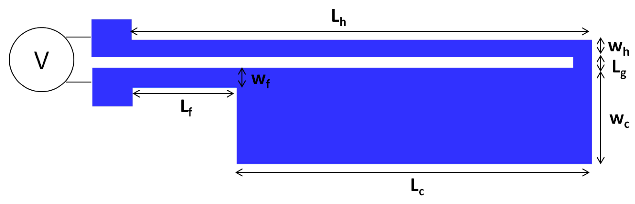
| Length of hot arm, | 200 | m |
| Length of cold arm, | 154 | m |
| Length of flexure, | 46 | m |
| Length of connector, | 3 | m |
| Length of gripping arm, | 203 | m |
| Width of hot arm, | 9 | m |
| Width of cold arm, | 55 | m |
| Width of flexure, | 9 | m |
| Width of gripping arm, | 9 | m |
| Thickness of silicon substrate | 20 | m |
| Thickness of silicon nitride | 0.6 | m |
| Thickness of air gap | 2.75 | m |
| Thickness of dimples | 2 | m |
| Thickness of Poly2 | 1.5 | m |
| Thickness of Metal | 0.5 | m |
| Property | Value | Unit |
|---|---|---|
| Density of polysilicon | 2.23 | g/(cm) |
| Young’s modulus of polysilicon, E | 158 | GPa |
| Poisson’s ratio of polysilicon, | 0.22 | - |
| Thermal expansion coefficient of polysilicon, | 2.80 | m/mK |
| Specific heat capacity of polysilicon, c | 100 | J/kgK |
| Thermal conductivity of polysilicon, | 32 | W/mK |
| Thermal conductivity of air, | 0.0262 | W/mK |
| Thermal conductivity of silicon nitride, | 25 | W/mK |
| Electrical resistivity of polysilicon | 30 | m |
© 2018 by the authors. Licensee MDPI, Basel, Switzerland. This article is an open access article distributed under the terms and conditions of the Creative Commons Attribution (CC BY) license (http://creativecommons.org/licenses/by/4.0/).
Share and Cite
Cauchi, M.; Grech, I.; Mallia, B.; Mollicone, P.; Sammut, N. Analytical, Numerical and Experimental Study of a Horizontal Electrothermal MEMS Microgripper for the Deformability Characterisation of Human Red Blood Cells. Micromachines 2018, 9, 108. https://doi.org/10.3390/mi9030108
Cauchi M, Grech I, Mallia B, Mollicone P, Sammut N. Analytical, Numerical and Experimental Study of a Horizontal Electrothermal MEMS Microgripper for the Deformability Characterisation of Human Red Blood Cells. Micromachines. 2018; 9(3):108. https://doi.org/10.3390/mi9030108
Chicago/Turabian StyleCauchi, Marija, Ivan Grech, Bertram Mallia, Pierluigi Mollicone, and Nicholas Sammut. 2018. "Analytical, Numerical and Experimental Study of a Horizontal Electrothermal MEMS Microgripper for the Deformability Characterisation of Human Red Blood Cells" Micromachines 9, no. 3: 108. https://doi.org/10.3390/mi9030108