Controllability of the nanopositioning platform is a challenging and difficult matter due to various problems associated with the platform; hence, a combination of different controllers is required. The initial approach to controlling the platform is to use a suitable damping controller for resonance, and a well-designed tracking controller. The damping controller used in this paper is the Integral Resonant Controller (IRC), and the tracking controllers are Integral (I) and Proportional and Integral (PI)-like Fuzzy Logic Controller (FLC). In this section, the traditional and proposed schemes to control the piezo-driven stage (nanopositioning platform) are explained.
4.1. Traditional Control Strategy
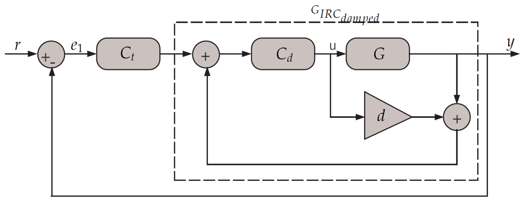
Considering the feedback configuration scheme in
Figure 6, the figure illustrates the method by which the tracking and damping controllers are combined and used together. Controlling the nanopositioning platform is achieved through the use of single-loop feedback. In nanopositioning, the classical tracking controllers are generally either Proportional Integral (PI) or Integral (I). The damping controller that is used in this paper is the IRC. The conventional tracking controller that is used in conjunction with IRC is a simple integrator.
The IRC controller is an effective and successful scheme for vibration damping, and it is used in a wide range of nanopositioner applications [
23]. This also has the desirable property of not exciting the higher frequency dynamics [
24]. The transfer-function of tracking controller and the damped system are given by:
The IRC can provide the appropriate damping to the system without providing tracking performance. The IRC scheme consists of a feed-through term and integral in the feedback, as is clear in
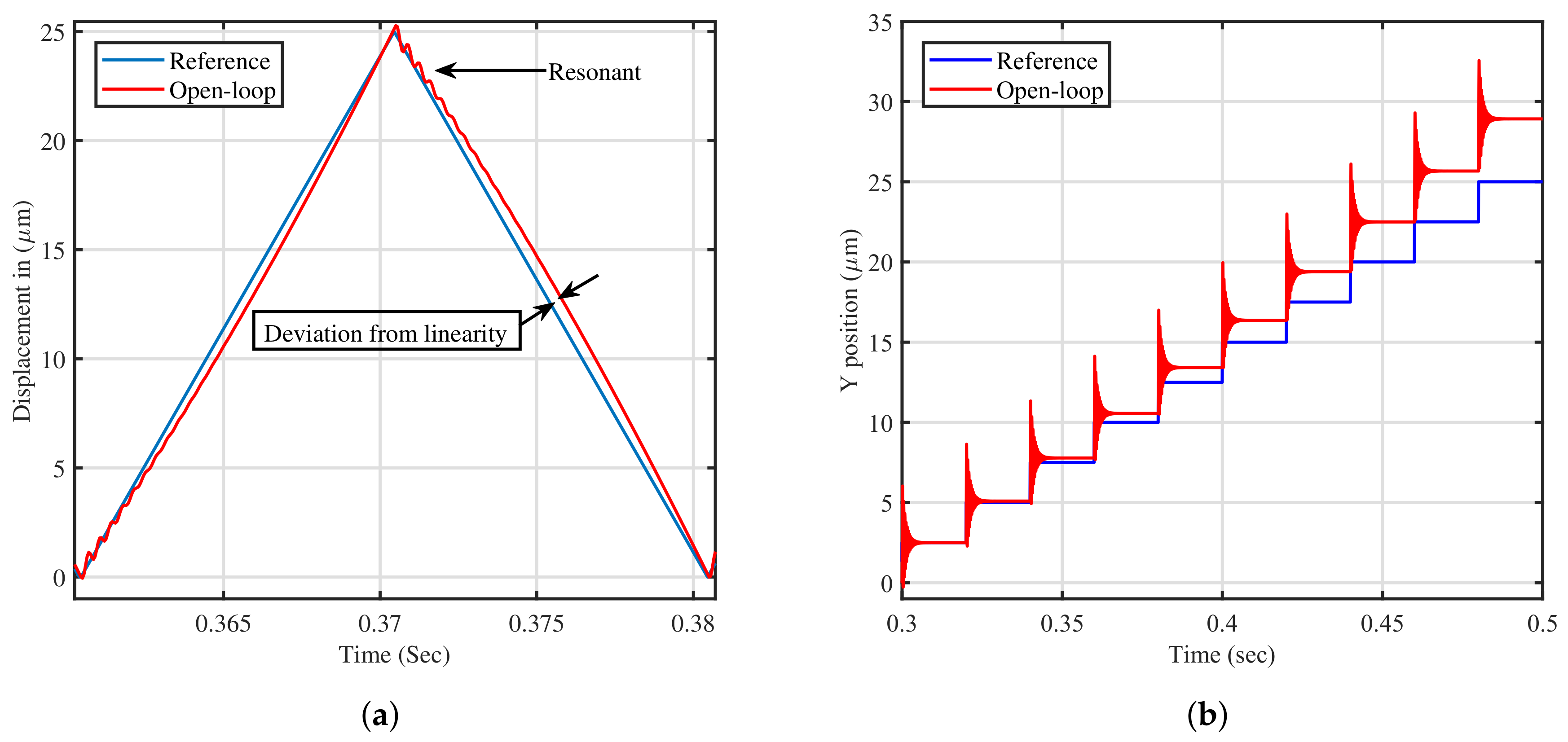
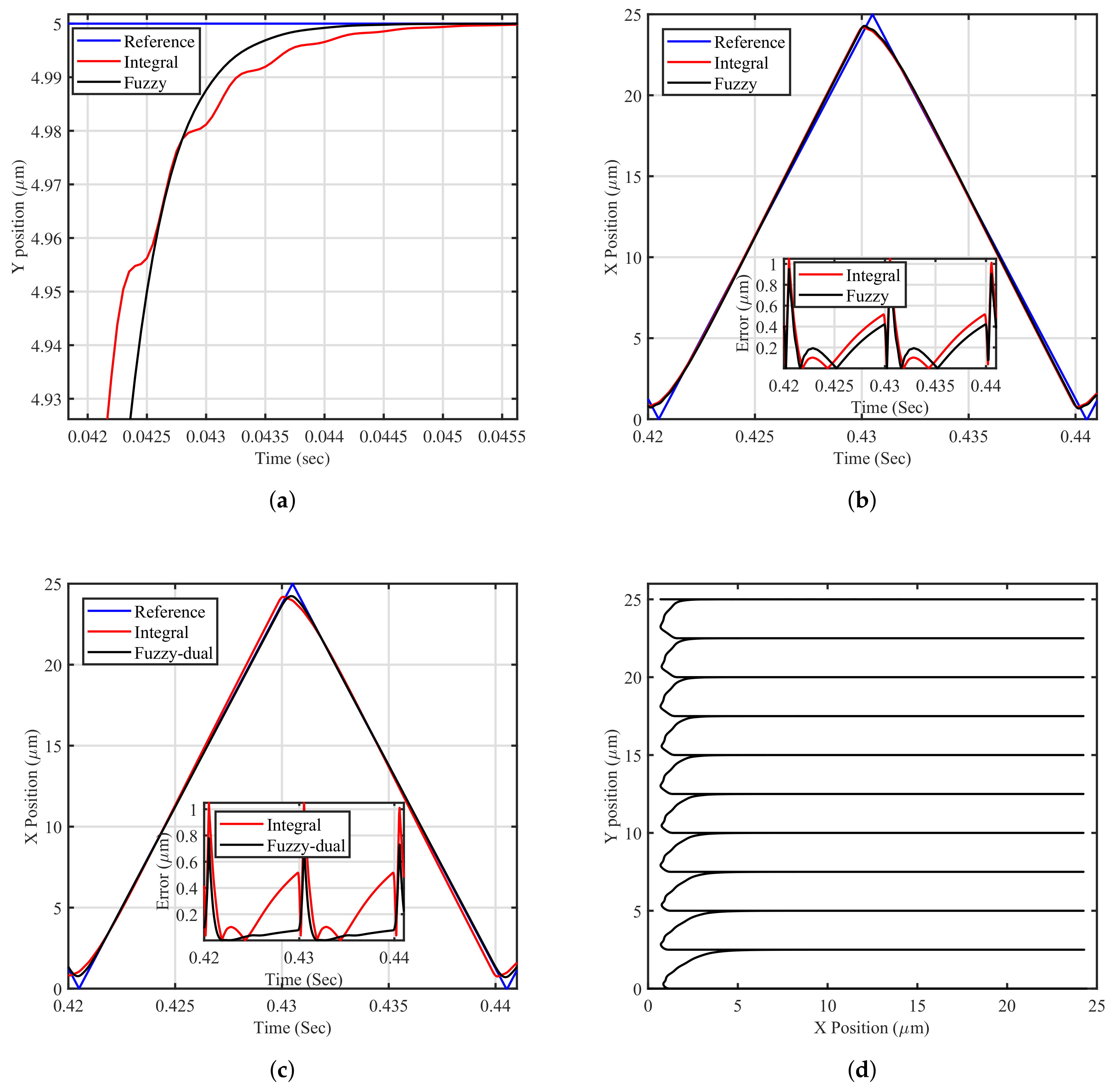
Figure 6. As will be illustrated in this paper, the traditional approach has clear limitations in tracking the reference signal. Tracking the staircase signal is challenging due to the resonant nature of the platform during sudden changes in the reference signal. Furthermore, tracking the triangular waveform is very difficult as it has high-frequency components and contains all the odd harmonics of its fundamental frequency [
5]. In order to track triangular trajectories with zero-error, the double-integral action is warranted. Employing a double-integral action through the traditional scheme is not directly applicable due to the phase profile of the integral action and stability issues in the nanopositioning platform.
4.2. Proposed Control Strategy
This work has thus far focused on linear controllers; however, nonlinear controllers have begun to be implemented in many studies. This research will investigate a nonlinear control strategy for better performance. The FLC will be used as a tracking controller to mimic the integral action, as will become clear in this section. The FLC is used in conjunction with the IRC instead of conventional (PI) or (I) tracking controllers in a single- and dual-loop fashion, as is clear in
Figure 7a,b.
The control algorithm of the FLC in
Figure 7a is mimicking the first-order integral action. As mentioned above, the closed-loop phase profile of the damped system does not furnish sufficient phase margin to allow for the implementation of a second-order integrator. Therefore, this paper proposes the implementation of a second tracking loop and it evaluates whether any improvement in positioning performance is achievable, as is clear from
Figure 7b. It could be argued that the FLC as tracking can be used in the inner-loop feedback. Use of this in the inner-loop, however, has yet to be justified due to improvement in phase shift profile if it is used in the outer-loop. The overall control algorithm in
Figure 7b consists of two first-order integral tracking controllers:
and
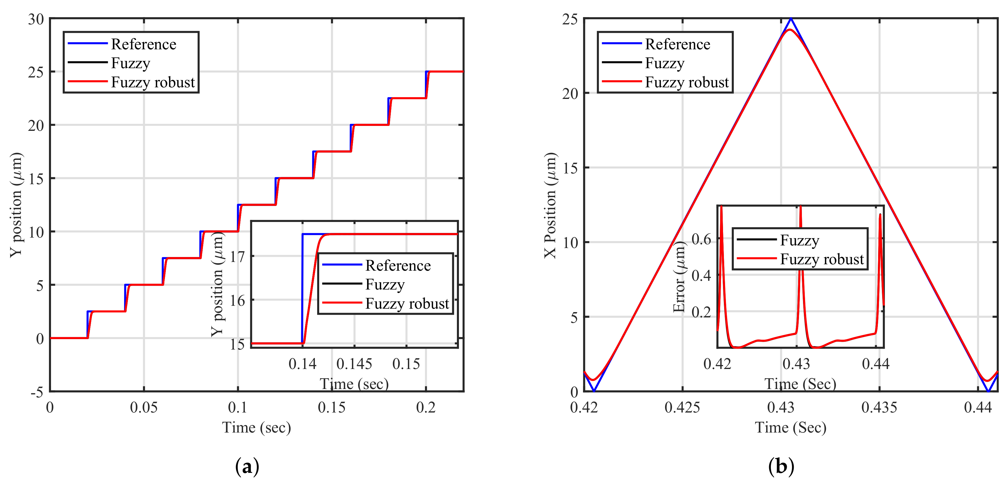
(mimicking). The FLC is preferred as opposed to the traditional controller in nanopositioning systems. This is due to the fact the system (piezo-driven stage) experiences the resonant mode inherently, and so the classical control will have clear limitations in damping the transient resonant mode, particularly given the fast response of the piezoelectric dynamics characteristics. The transient resonant mode will cause vibrations in terms of overshoot at any sudden change in the input signal, which will lead to inaccuracy in nanopositioning applications. The FLC can improve the dynamic characteristics in terms of reducing the overshoot. Below, the FLC components are described first, and the stability analysis of the proposed methods is then presented.
4.3. Fuzzy System Components
The fuzzy system is knowledge-based, and human experience can be incorporated into its design by mimicking expert knowledge via the fuzzy rules [
25]. The fuzzy rules are linguistic rules characterised by and linked with conditional statements of ’If-then’. These sets of linguistic conditional statements represent the control situations. The behaviour of the FLC is highly restricted by its control table decisions, which contain the fuzzy rules. In
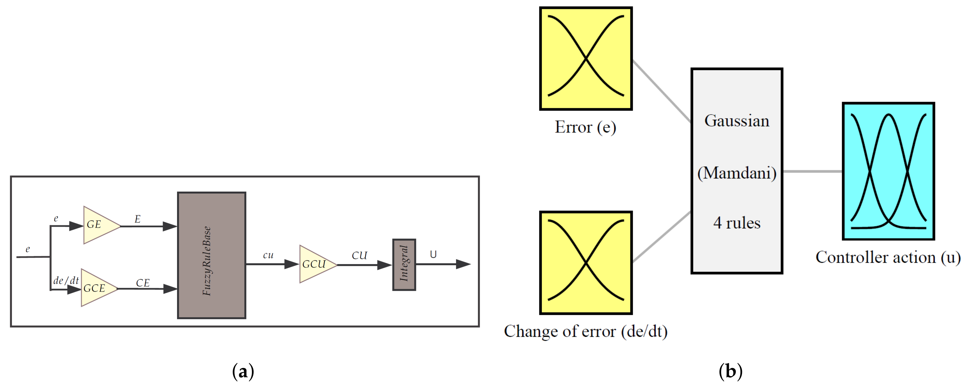
Figure 8a, a clear illustration of the FLC incremental gains’ distribution is presented. It can be seen from
Figure 8b that the proposed controller is formed using four rules in order to make it simple.
The control input variables (crisp inputs) must be fuzzified before applying them to the control algorithm of the FLC. Normally, inputs to the FLC (state variables) include the error and change of error, as is clear from
Figure 8b. In order for the controller to continuously account for the universe of discourse, a functional definition can be used to clarify the membership function of a fuzzy set. There are several types of membership function used in this regard, such as triangular, trapezoidal and bell-shaped functions. These membership functions are the most popular types of many engineering applications [
26].
A Gaussian wave is used in this design, as can be seen in
Figure 8. The proposed membership function is a plot of the function
versus
, where the horizontal
x-axis represents the universe of discourse that covers the entire range of possible values for a chosen variable, and the vertical
y-axis represents the membership value of the fuzzy set (certainty). In the fuzzy logic, membership is a matter of degree; it varies from 0 to 1 depending on the percentage allocated to each control situation. When implementing the membership function, the universe of discourse (crisp values) for the FLC is normalised within [−1,1] for the leftmost and rightmost, respectively. Gaussian membership functions are fuzzy membership functions that represent the linguistic terms; these functions are relatively popular in the fuzzy system literature and the output is very smooth. Hence, in this design, the Gaussian membership function is used to achieve a smoother control action and avoid an abrupt change in the controller action. The reason for this is that the Gaussian membership functions are smooth and non-zero at all points; therefore, no discontinuities in their derivatives are present.
The overlap of the membership is considered to be 25%, and the membership function at the overlap is equal to 0.5; this will keep the control action smooth in the case of a sudden change. The implementation of the membership function for the error and change of error is based on using two linguistic descriptions (
N and
P). Three linguistic descriptions are used to quantify the control action (
N,
Z and
P), as is clear in the
Table 1. It is important to note here that the membership functions for error, the rate of error and control action are selected to be the same (Gaussian).
In this research, the FLC is proposed as a tracking controller, not as a damping controller. Therefore, the fuzzy rules are designed based on the damped system dynamics using simulation. Using the simple logic, the control rules that make sense are set. The statement error is P, or N can represent the situation where the response of the system is at a significant distance from the setpoint. The statement error is Z, and this can represent the situation where the output response is the very close set point, or the system is reaching equilibrium and the error is null. The following rules are defined:
If the error is P and rate of error is P then the control action is P,
If the error is N and rate of error is N then the control action is N,
If the error is P and rate of error is N then the control action is Z,
If the error is N and rate of error is P then the control action is
The Mamdani inference and centroid defuzzification are used in this work. Here, error (the difference between set point and actual process value) and change in error (the difference between current and past error) are the inputs to the fuzzy system. In the case of the fuzzy rule, the conditions can be satisfied (as opposed to crisp rules) smoothly; this has the desired effect of being able to interpolate between two rule conditions. This results in a smooth transition from one state to the other in the induced fuzzy control surface because of the Gaussian membership function.
With reference to
Figure 8a, scaling factors are important parameters to tune into the FLC as they can scale the universe of discourse. Changing the scaling factors will affect the meaning of the linguistics that forms the basis of the fuzzy logic controller definition because it is redefining the horizontal axis. It can be concluded that scaling factors play a similar role to the gains of the conventional controller, as will become clear in the following section; they can also be a source of oscillation problems. Although the selection of suitable values of scaling factors is based on using the trial and error method, this is ruled out, and the relationship between scaling factors and their conventional counterpart is derived in the following section.
4.4. Stability Analysis of the Proposed FLC
In this paper, the rules are designed based on an analogy with the classical control system modelling. The dynamic characteristics of the proposed control system are considered as the fuzzy model, and the linguistic description of the dynamic characteristics can be used to obtain a set of fuzzy rules. The conventional PI control law is given by:
where
is the error as function of time,
is the integral gain,
is the control output as function of time,
is proportional gain and
is an integral constant. By deriving the control law of the conventional controller, it can be obtained that:
The derivation of the control action means the trend and which can be referred to as
u. The derivation of the error can also be referred to as ▽
e, and Equation (
6) can thus be written as follows:
An incremental controller adds a change in control signal
u to the current control signal. The incremental FLC is a type of fuzzy logic control systems where the controller output is not the control action “
u”, but the controller output is the change of the control action
u. The FLC incremental
u is normalised and scaled as the linear non-invariant function of normalised error and normalised change of error and can be expressed as follows:
where GE, GCE and GCU are the scaling factors of error, change in error and incremental output variable, respectively. The function
f is the input–output map of the normalised FLC incremental depends on many variables. From Equation (
8), the FLC incremental
u can be written as follows:
The relationship between the scaling factors for the FLC and the conventional controller is derived based on an analogy of the conventional controller by comparing Equations (
7) with (
9) as is clear below:
where
F is an operation for fuzzification and
D for defuzzification. From Equation (
10), it is found that
multiplied by
is equivalent to
. In this paper, the FLC is mimicking the integral action only and this can be done by setting the value of GCE to a small value. As noted from Equation (
10), the proportional gain
is dependent on GCE. Hence, as
, the effect of the proportional gain is almost negligible. Therefore, the effect of the zero added by the FLC is tiny.
Referring to
Figure 7a, the overall transfer function of the system can now be determined as follows:
Thus, the characteristics equation of the proposed single-loop fuzzy control strategy is given by:
As the value of
is usually small, it can be safely neglected in the overall analysis. The adequate feed-through term is independent of the parameters of the FLC and adequate value can be determined as in the following equation for the proposed single-loop fuzzy control strategy:
In order to preserve stability and to increase the bandwidth, the values of the damping and tracking gains must obey the following quantities:
Therefore, tuning of the scaling factors (GCU and GE) is important in designing the FLC. Referring to
Figure 7b, the overall transfer function of the system can now be determined as follows:
Thus, the characteristics equation of the proposed dual-loop fuzzy feedback scheme is given by:
Overall stability is examined for the proposed control scheme by applying the Routh–Hurwitz stability criterion. The characteristics equation of the proposed scheme is further analysed to determine the range of
,
,
and
d required for closed-loop stability. For this characteristic polynomial to have all roots with negative real parts, the coefficients of all the “
s” terms must be positive. Noting that
,
and
are positive results in the following inequality to be a necessary condition for stability. Similar to the single-loop fuzzy, the adequate feed-through term is independent of the parameters of the FLC. The adequate feed-through term
d, the damping gain
and the tracking controller gains
and
are obtained. They are presented in Equations (
17)–(
19) to demonstrate that the relationship between the scaling factors for the FLC and the conventional controller is known. For simplicity purposes in this design, the normalisation factors are distinctively separated from the scaling factors:
Although tuning the control action scaling factor alone can result in satisfactory behaviour, it is found that, in some cases, it can produce oscillation, whilst tuning the error scaling factor in conjunction with the control action scaling factor can result in less vibration and at the same time it can mimic the classical integral action. The selection of scaling factors is undertaken in a fashion to imitate the conventional integral controller. The main advantages of the proposed FLC are smooth control, removing the steady-state error, and better tracking performance, as will become clear in the following section. However, the limitation of the proposed FLC is the increase in the delay of the system using the dual-loop control strategy. Stability boundaries are determined using the trial and error methods to tune the scaling factors, in order to mimic the integral action that is a limitation of the proposed method.
