Article

Photocatalytic Properties of a Novel Keratin char-TiO2 Composite Films Made through the Calcination of Wool Keratin Coatings Containing TiO2 Precursors

1
Research Centre for Functional Textile Materials, School of Textile Science and Engineering, Xi’an Polytechnic University, Xi’an 710048, China
2
Key Laboratory of Functional Textile Material and Product of Ministry of Education, Xi’an Polytechnic University, Xi’an 710048, China
3
School of Design, University of Leeds, Leeds LS2 9JT, UK
*
Author to whom correspondence should be addressed.
Catalysts 2021, 11(11), 1366; https://doi.org/10.3390/catal11111366
Submission received: 28 October 2021 / Revised: 11 November 2021 / Accepted: 11 November 2021 / Published: 13 November 2021
(This article belongs to the Special Issue Environmental Catalysis for Water Remediation)

Abstract

:
In this study, the photocatalytic properties of novel keratin char-TiO2 composite films, made through the calcination of wool keratin coatings containing TiO2 precursors at 400 °C, were investigated for the photodegradation of organic contaminants under visible light irradiation. Its structural characteristics and photocatalytic performance were systematically examined. It was shown that a self-cleaning hydrophobic keratin char-TiO2 composite film containing meso- and micro-pores was formed after the keratin—TiO2 precursors coating was calcined. In comparison with calcinated TiO2 films, the keratin char-TiO2 composite films doped with the elements of C, N, and S from keratins resulted in decreased crystallinity and a larger water contact angle. The bandgap of the char-TiO2 composite films increased slightly from 3.26 to 3.32 eV, and its separation of photogenerated charge carriers was inhibited to a certain degree. However, it exhibited higher photodegradation efficiency to methyl blue (MB) effluents than the pure calcinated TiO2 films. This was mainly because of its special porous structure, large water contact angle, and high adsorption energy towards organic pollutants, confirmed by the density functional theory calculations. The main active species were 1O2 radicals in the MB photodegradation process.

Graphical Abstract

1. Introduction

The semiconductor TiO2 can be used in a wide range of applications such as paints, cosmetics, photoelectric sensors, energy conversion and storage, air and water purifications, and removal of organic pollutants [1]. With respect to photocatalysis, it is considered one of the most excellent photocatalytic materials due to its low cost, less toxicity, good physical and chemical stabilities, and high photocatalytic activities [2]. In general, TiO2 has three phase structures, namely rutile, anatase and brookite, and anatase and rutile TiO2 can be applied in the field of photocatalysis [3]. The theoretical band gaps are 3.2 eV for anataseTiO2, and 3.0 eV for rutileTiO2, and their corresponding absorption edges are separately located at 388 nm and 414 nm [4]. In comparison with rutile TiO2, anatase TiO2 exhibits stronger photocatalytic activity due to its high local state density, abundant surface hydroxyl radicals, and long lifetime photogenerated charge carriers [5]. However, both can only be excited by ultraviolet rays [6], and their photocatalytic activities are impaired to some degree due to the rapid recombination of photogenerated electron-hole pairs [7]. However, the decreased particle size of TiO2 particles can lead to the agglomeration phenomenon, which will hinder the incidence of light into the active center [8]. In addition, the separation, recovery, and reuse of nano-scaled TiO2 photocatalysts pose many environmental, health, and safety problems in practical application [9].
Doping TiO2 with metal or non-metal elements is regarded as an effective and feasible strategy for enhancing light harvesting and minimizing the energy band gap of TiO2 [10]. It broadens the photo-response range towards visible light or infrared, thereby inhibiting the recombination of photogenerated electron-hole pairs [11]. Many efforts have been devoted to improving the photocatalytic activity of TiO2 by using metal or non-metal elements doping, core-shell structure constructing, and heterogeneous composition. Compared with metal ions doping, the non-metal elements doping into TiO2 have the benefits of simple doping process, high photocatalytic stability, and activity [12]. It is demonstrated that non-metal elements like N, C, S, and P can efficiently improve the photocatalytic activity of TiO2 [13]. The C element possesses high thermal stability, which can promote the adsorption of organic molecules on the TiO2 surface and produce a hybrid orbital over the valence level of TiO2, thereby enhancing the separation of electron and hole pairs [14]. Likely, the interstitial or substitutional N element doping can lead to the red-shift of the absorption edge of N-doped TiO2, which results in the formation of oxygen vacancies because its atomic size is very close to that of oxygen [15]. The band gaps of N-doped [16] and W, N co-doped [17] anatase TiO2 are reduced from around 3.2 eV to 2.20 eV. The co-doping of N and S elements is beneficial to increase the electronic conductivity of N, S co-doped TiO2 by creating localized states in its band gap structure [18].
TiO2 film is endowed with unique mechanical, physical, and chemical features, including tunable band gap, high refractive index, large surface area, and enhanced photocatalytic activity [19]. It can be applied to various substrates instead of granular materials, which greatly saves costs, prevents secondary pollution, and is widely used in sensors, sunscreen, environmental purification, water decomposition, self-cleaning and antibacterial materials [20]. The technique for preparation of TiO2 film includes chemical vapor deposition, spray, sputtering, liquid deposition, and sol-gel methods. The sol-gel spin-coating process is the simplest and most favored procedure to fabricate TiO2 film due to its high efficiency, uniformity, and reliability, which can be performed at room temperature without using special equipment [19].In this process, the precursor of metal alcohol oxygen compound or inorganic metal salt is first hydrolyzed and then polycondensed to form a TiO2 colloidal suspension, and finally deposited on a support substrate via the dip coating or spin coating to construct a film with a certain thickness [21]. It is reported that the thickness of TiO2 film influences the photodegradation performance [22]. By controlling the concentration and viscosity of the sol-gel solution, photocatalytic films with different porosities and textures can be obtained [23]. The substitutional and interstitial N doping into rutile (110) orientated TiO2 films can induce reverse rutile to anatase phase transition at high temperature [24].
It is known that wool is primarily made of 95% keratin proteins, consisting of 7–20 mol% cysteine residue and around 0.1% lipid and 0.5% minerals [25]. Wool keratin is a kind of polypeptide that is constituted by different amino acids. These amino acids are cross-linked by the inter-molecular bonding resultant from the disulfide cysteine amino acid and the inter-and intra-molecular bonding resultant from polar and nonpolar acids [26]. Besides, wool keratin is stabilized by other bonds, including hydrophobic, hydrogen, and ionic bonds [26]. Wool fibers are a kind of natural protein textile material having unique properties, which depend upon its chemical composition and morphological characteristics [27]. The water insolubility, chemical resistance, biodegradability, and good mechanical properties of wool fibers are mainly determined by the disulfide bond of keratin [28]. However, under the action of alkaline, or hydrolytic enzymes, or reducing/oxidizing chemical reagents, the disulfide bonds can be broken, thereby leading to the hydrolysis of wool keratin [29]. It is confirmed that the C, N, O, and S co-doping from wools can enhance the photocatalytic activity of rutile TiO2 particles [30]. The primary reactive radical of TiO2 modified wool powders are holes and •O2, 1O2, and •OH also take part in the photodegradation of MB dyes under visible light irradiation [31]. Porous wool keratin film can be applied for filtration, air purification, and tissue engineering [32]. However, TiO2 nanoparticles doped with wool keratins might be prone to alkaline effluents due to the nature of keratin. It is envisaged that keratin char-TiO2 nanoparticle composite catalysts could still be doped with the elements of C, N, S from keratin and might still have higher efficiency while resistant to harsh alkaline effluents conditions. The keratin hydrogel-TiO2 composites have been developed for the high-efficiency adsorption and photodegradation of trimethoprim under UV and visible light irradiation [33]. TiO2 particles are dispersed in polylactic acid (PLA) solution in the presence of feather keratin and clay to prepare the keratin/PLA/TiO2/clay nanofibers. The as-prepared nanofibers not only adsorb and remove the MB dye from the aqueous solution but also degrade the MB dye under UV irradiation [34]. Currently, neither keratin char-TiO2 nanoparticle composite films have been investigated, nor have the porous films composed of TiO2 nanoparticles doped with the elements C, N, and S from keratins char been reported.
In the present work, a novel type of keratin char-TiO2 composite films doped with C, N, and S elements from wool keratins was prototyped through the calcination of keratin coatings containing TiO2 precursors. The photocatalytic structures and properties of the keratin char-TiO2 composite films were investigated, and its photodegradation efficiency to MB under visible light irradiation was reported. Wool keratin was extracted from wool fibers firstly using reducing agents. A spin-coating technique was then alternatively applied to deposit wool keratin and TiO2 precursors films on quartz glass substrates, followed by annealing at 400 °C. The morphology, surface roughness, phase structure, microstructure, chemical bonding state, hydrophilic properties, energy band structures, and separation of photoinduced charge carriers of the as-prepared keratin char-TiO2 composite films were analyzed. The photocatalytic mechanism of its photodegradation to MB dyes was elucidated. The role of wool keratin’s C, N, and S elements on the photocatalytic properties of keratin char-TiO2 composite films were verified by density functional theory (DFT) calculations.

2. Results and Discussion

2.1. Molecular Weight of Wool Keratins

The electrophoretic mobilities of wool keratins and marker proteins were compared to estimate the molecular mass of as-prepared wool keratins [35]. The electrophoretic separation patterns of standard and wool keratins are depicted in Figure 1. The molecular weight from 14 to 97 kDa was applied to line a of Figure 1 for calibration. The electrophoretic patterns of wool keratin (lines 1 and 2) indicated that the broad dull bands with a low molecular weight of 31–14.4 kDa were ascribed to the high sulfur proteins of wool keratin. In contrast, the high molecular weight bands (66.2–43 kDa) correlated with the wool cortex’s low-sulfur intermediate filaments proteins having a typical α-helix secondary structure [28].

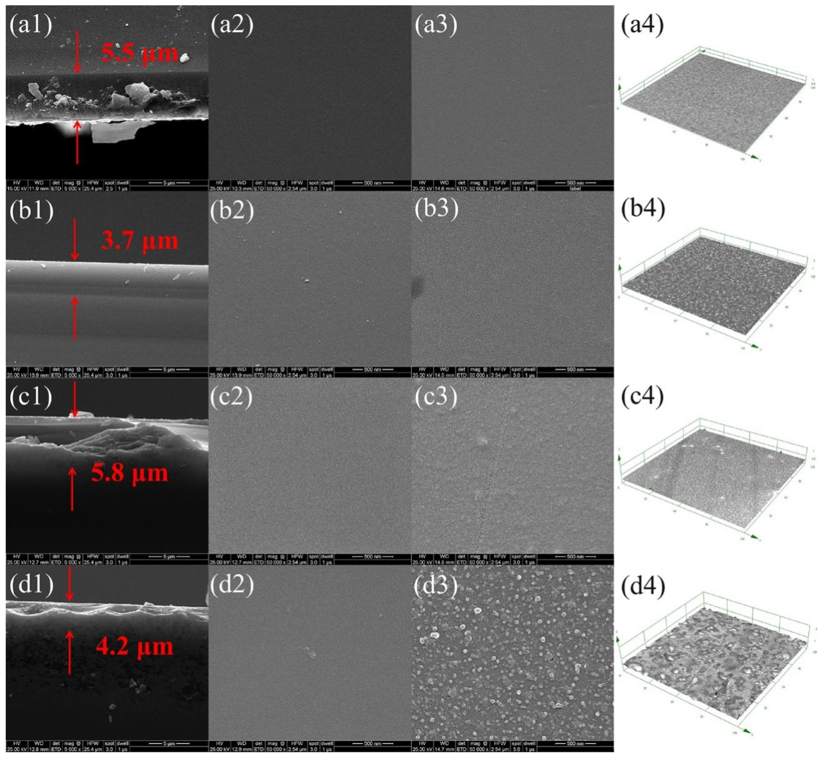
2.2. Morphology and Surface Roughness of As-Prepared Keratin char-TiO2 Films

The FESEM and laser microscopy images of the TiO2 films and keratin char-TiO2 composite films before and after calcination are displayed in Figure 2. It was noticed that a compact coating was homogeneously deposited on the glass substrate for all four films. After calcination, the surface roughness increased from 1.0 to 3.2 nm for the TiO2 films and from 3.2 to 9.7 nm for the keratin char-TiO2 composite films with spot-like features. This was because of the crystallization growth of TiO2 grains with phase changes from amorphous to anatase at 400 °C [36]. The surface roughness of the keratinchar-TiO2 composite films was larger than that of the TiO2 ones, suggesting the macromolecular chains of wool keratin could lead to the agglomeration of TiO2. The annealing treatment accelerated the crystal growth and agglomeration of TiO2 nanoparticles with improved crystallinity [20], contrary to the previous reports [37]. The cross-section FESEM images showed that the thicknesses of the TiO2 films and keratin char-TiO2 composite films were in the sub-micrometer range with good adherence to the substrate. The magnified FESEM images of their cross-sections and surfaces demonstrated that many meso- and micro-porous holes existed in both the internal and surface of all the four films, which was in agreement with TiO2 film generated from the sol-gel process [38]. After calcination, more pores were produced in the keratin char-TiO2 composite film.

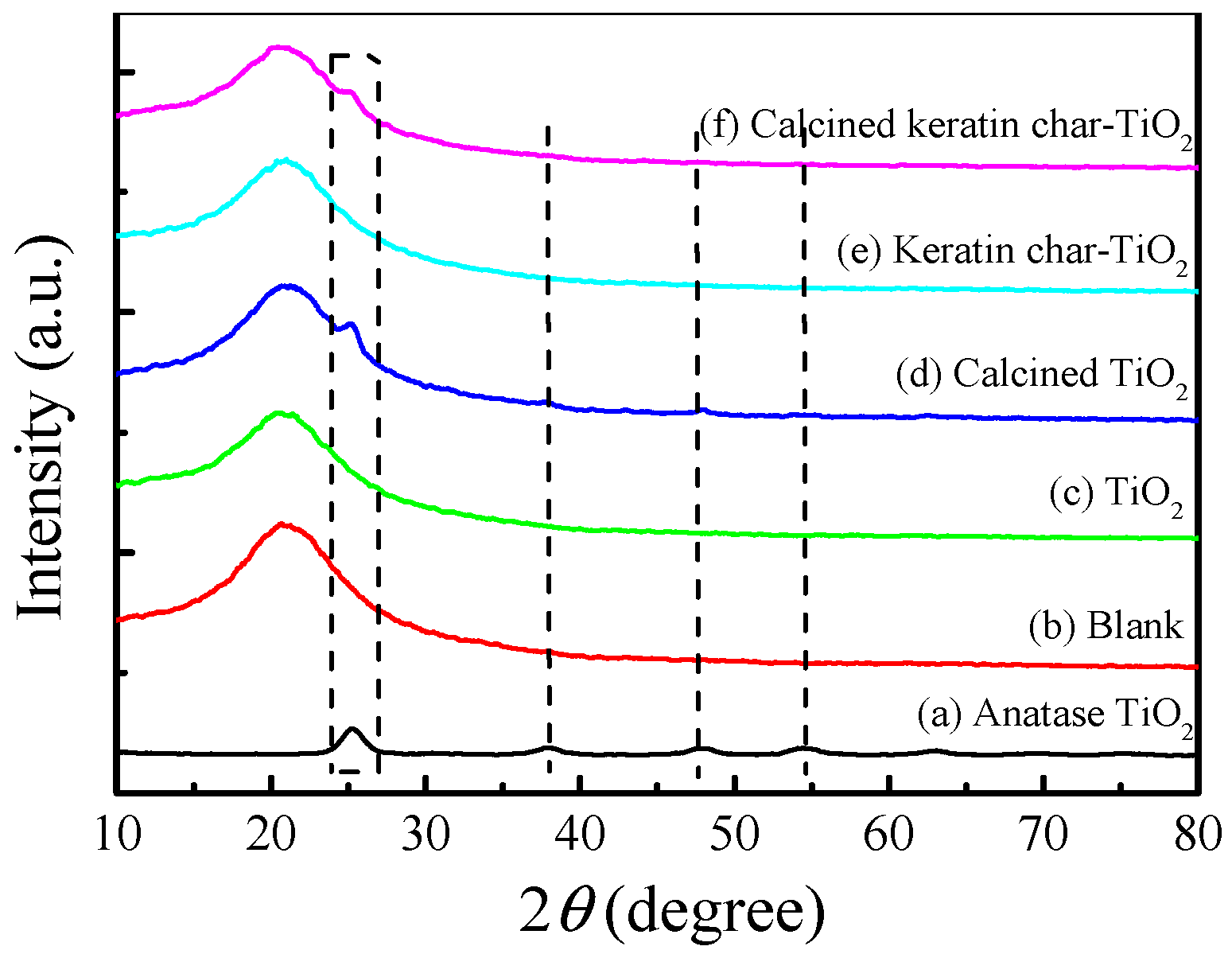
2.3. Crystal Structures

The XRD patterns of the TiO2 films and keratin char-TiO2 composite films before and after calcination, as well as TiO2 particles, are manifested in Figure 3. The broad diffraction peak at around 2θ = 22° in the XRD patterns for all the films belonged to the characteristic peak of quartz glass [39]. Prior to annealing, no diffraction peak could be found in the patterns of the TiO2 and keratin char-TiO2 films, implying TiO2 was an amorphous structure. After calcination, a relatively weak diffraction peak at 25.1° was detected in the patterns of the calcined films because of the low loading of TiO2. This was attributed to the (101) crystal plane of anatase phase TiO2 (JCPDS No. 21-1272). The peak intensity of the calcined TiO2 film was stronger than that of the calcined keratin char-TiO2 composite film along the preferred (101) plane growth orientation. Thus, the incorporation of wool keratin into TiO2 affected the crystallization of TiO2 to a certain degree. For comparison, the XRD pattern of pure TiO2 nanoparticles indicated that the characteristic diffraction peaks at 25.1°, 37.8°, 47.8°, 54.2°, 55.4°, 62.4°, and 75.3° were well matched with the (101), (004), (200), (105), (211), (204), (116), (220), and (215) crystal planes of tetragonal anatase TiO2 [40]. According to the Scherrer formula [41], the mean crystal size of pure TiO2 nanoparticles was calculated to be 9.6 nm by measuring the diffraction peak widths of (101), (004), and (200) crystal planes.

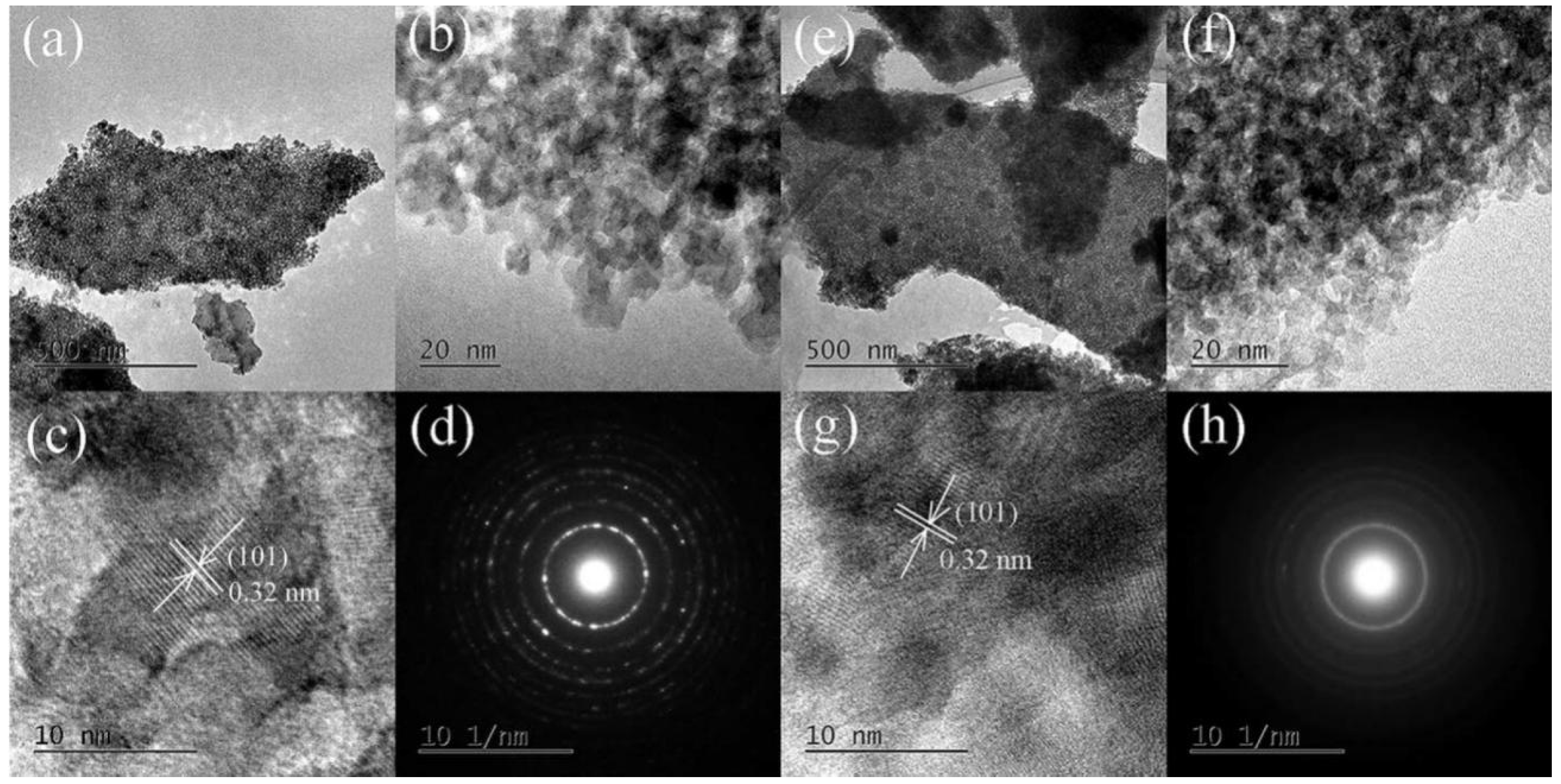
2.4. Microstructures of the Calcined Films

The TEM images and selected area electron diffraction (SAED) patterns of the calcined TiO2 film and calcined keratin char-TiO2 composite film are presented in Figure 4. It was seen that after calcination, the crystalline TiO2 particles were formed, and the particle sizes for both films were less than 10 nm with a uniform distribution, which were well consistent with the calculated values from XRD. The crystal lattice spacing in high-resolution TEM images were estimated to be 0.32 nm for both the calcined TiO2 film and calcined keratin char-TiO2 composite film, which were close to 0.35 nm of anatase TiO2 [42]. Moreover, the crystalline TiO2 nanoparticles were surrounded by disordered carbon layers. The carbon-type structure was in-situ formed in the TiO2 films calcined at 400 °C because of the oxidation of hydrocarbon compounds in air. However, the lattice spacing of carbon was not found primarily because the calcination temperature was not high enough to produce the crystal structure of carbon [43]. As shown in SAED patterns, the intensities of the diffraction rings of calcined TiO2 nanoparticles were stronger than those of the calcined keratin char-TiO2 ones. This implied that the crystallinity of the calcined TiO2 nanoparticles in keratin char-TiO2 composite film was not as great as pure TiO2 particles. Namely, the smaller crystallinity was probably caused by a mixture of TiO2 and amorphous char/carbon structures. As a result, the in-situ hybridization of C with TiO2 for both the calcined films might improve the separation of photoinduced electron and hole pairs via the electronic interaction between C and TiO2 crystals in the films. Besides, the N and S doping with TiO2 could further enhance the separation of photoinduced charge carriers in the calcined keratin char-TiO2 composite film [30].

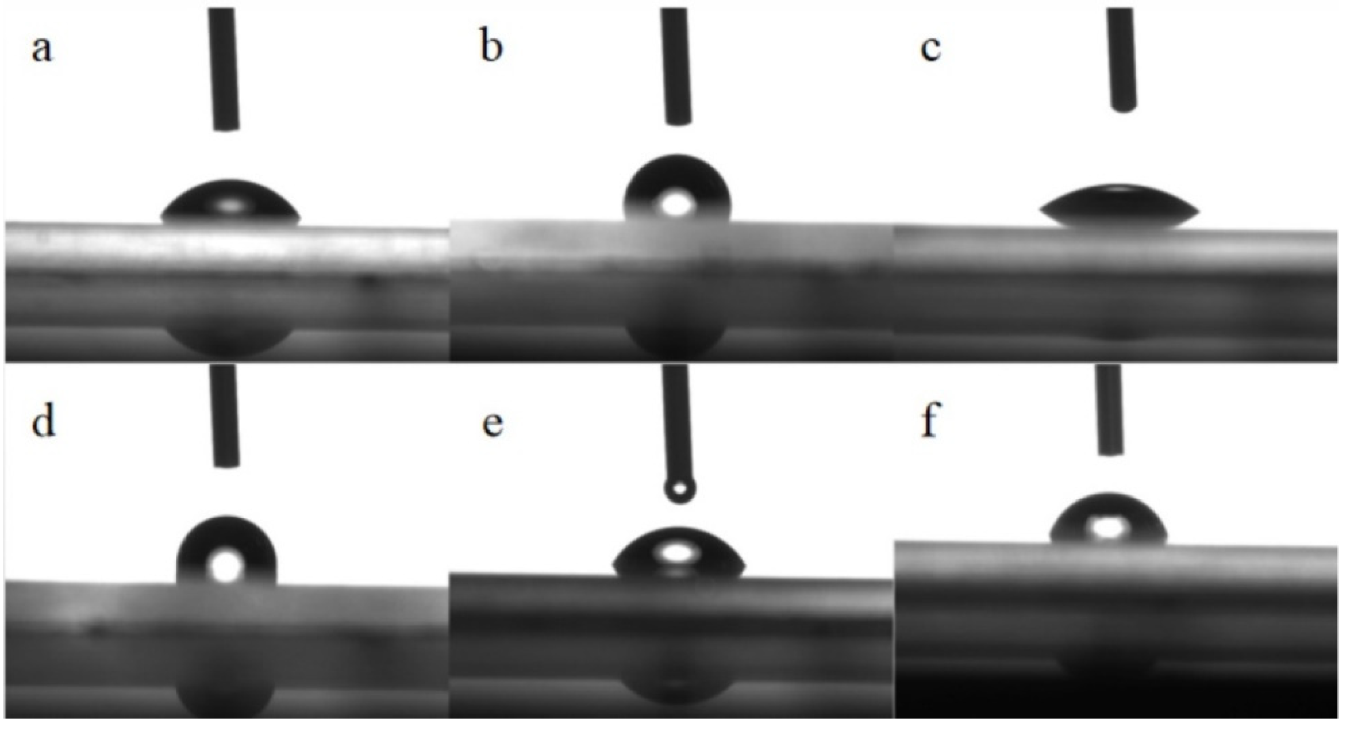
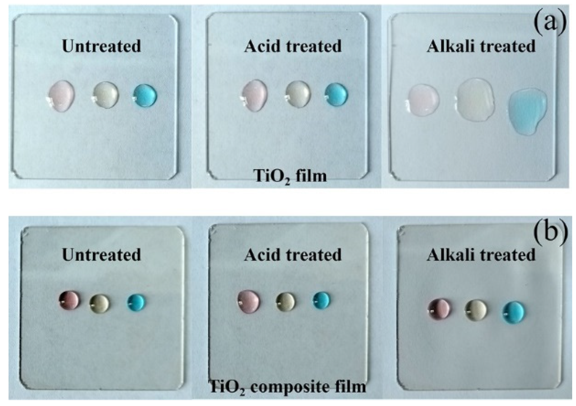
2.5. Surface Contact Angles

The optical images of the water contact angles for all the films are represented in Figure 5. The water contact angle of the blank quartz glass was 58.0°. The hydrophilicity of the calcined TiO2 film became better, and its contact angle decreased to 36.2° from 90.2° after calcination at 400 °C. The hydrophilic surface might be due to the removal of organic components, the structure change from amorphous to anatase phase, and the increased hydroxyl groups [44]. When wool keratin was introduced into TiO2, the contact angle of the keratin char-TiO2 composite film increased to 96.6° because of the hydrophobic features of wool keratin and the special topography of film [45]. However, the UV irradiation could improve the keratin char-TiO2 composite film’s hydrophilicity to some extent with a water contact angle of 72.3°. The water contact angle of the calcined keratin char-TiO2 composite film decreased to 61.7°, implying the limited enhanced wettability. Therefore, the hydrophilic behavior of the films played a positive role in the photodegradation of the MB dye solution [44].

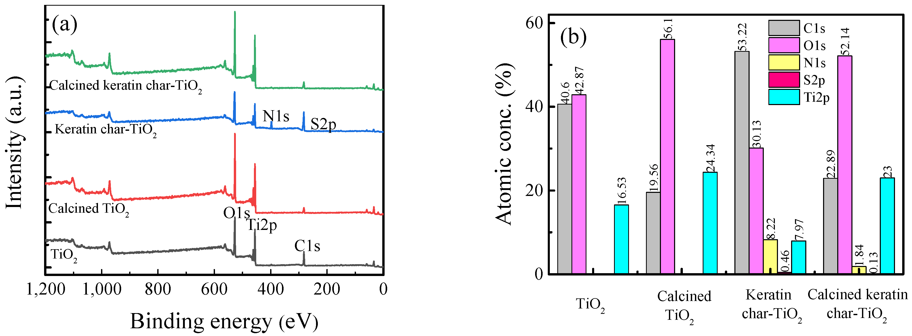
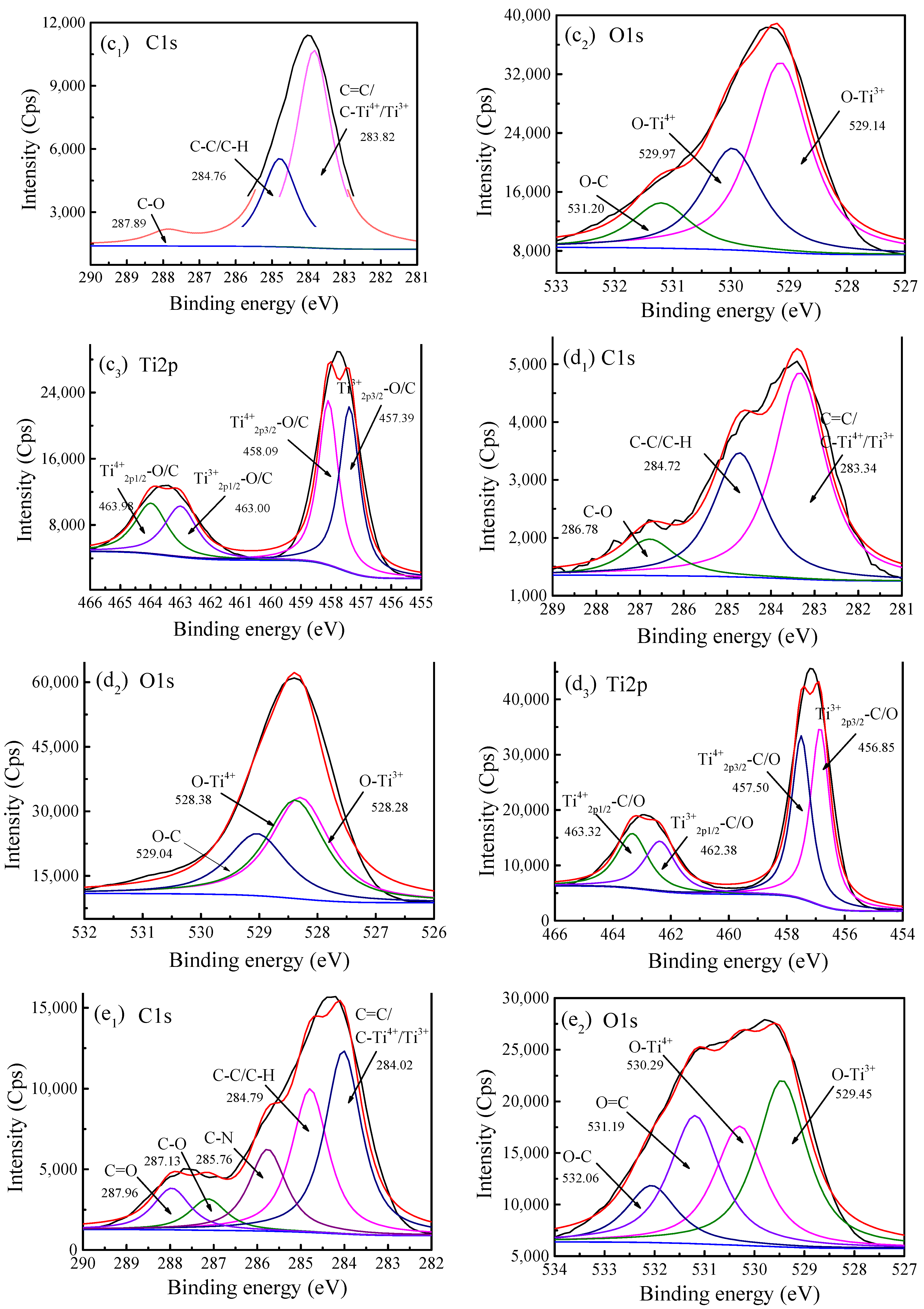
2.6. Chemical Bonds and Element Analyses

The XPS spectra of the TiO2 films and keratin char-TiO2 composite films before and after calcination are revealed in Figure 6. The XPS survey spectra and chemical elements confirmed the doping of N and S elements of keratins withTiO2. The relatively high contents of the C element in both the uncalcined films (TiO2 40.60%, keratin-TiO2 53.22%) suggested that the organic carbon layers acting as the photosensitizer existed in the boundaries of TiO2 grains, which would result in the interstitial carbon doping into TiO2 [46]. The intensities of Ti and O elements in the TiO2 films and keratin char-TiO2 composite films were distinctly enhanced after calcination owing to the loss of organic substances at high temperatures. For the stoichiometric formation of TiO2,after calcination, the atomic concentration ratios of O to Ti were reduced from 2.59 to 2.30 for the TiO2 films and from 3.78 to 2.27 for the keratin char-TiO2 composite films. The corresponding atomic concentrations of the C element decreased to 19.56% for the TiO2 films and 22.80% for the keratin char-TiO2 composite films.
The high-resolution XPS spectra indicated that C=C (carbide)andC-Ti4+/Ti3+, C-C/C-H, and C-O groups existed in the C1s spectra of all the films. The number of active sites might be increased because of the introduction of C element into the lattice of TiO2, which was caused by the oxidation and decomposition of organic matter at 400 °C [47]. It meant the Ti-C or Ti-O-C bonds between the Ti of the TiO2 and carbon content were formed at this annealing temperature [48]. Hence, C doping could enhance the photocatalytic properties of TiO2 film. The groups of O-Ti3+ (lattice oxygen), O-Ti4+ (TiO2), and O-C (caused by organic components from isopropyl alcohol, acetic acid, and TTIP) presented in the O1s spectra of all the films. Additionally, Ti3+2p3/2-O/C, Ti3+2p1/2-O/C, Ti4+2p3/2-O/C, and Ti4+2p1/2-O/C groups were fitted in the Ti2p spectra of all the films [17]. Ti3+ acting as an active site for oxygen desorption was assigned to the partial substitution of O atoms by C atoms in TiO2, promoting the separation of photogenerated electron and hole pairs [13].
In the cases of the keratin char-TiO2 composite films, besides the above-mentioned fitted subpeaks in the C1s, O1s, and Ti2p spectra, C-N and C=O groups were fitted in the C1s spectra, and the corresponding O=C group was deconvoluted in the O1s spectra. Likely, the N1s XPS spectrum could be deconvoluted into N-C and N-Ti4+/Ti3+ (substitutional and interstitial states of N atom in TiO2 lattice) [46], and the S2p spectrum was fitted into S-S, S-H, and S-Ti4+/Ti3+ [49]. After calcination, the S-H group disappeared, but the other two S-S and S-Ti4+/Ti3+ were identified. Furthermore, the fitted groups of Ti3+2p3/2-O/C/N/S, Ti3+2p1/2-O/C/N/S, Ti4+2p3/2-O/C/N/S, and Ti4+2p1/2-O/C/N/S were well consistent with the high-resolution XPS spectra of C1s, O1s, N1s, S2p, and Ti2p. Consequently, the multi-element doping of C, N, and S elements in carbon layers was realized in the keratin char-TiO2 composite films, and the calcination treatment was helpful for the crystallization growth of C, N, and S co-doped TiO2 grains while the structure was changed from amorphous to anatase phase [50]. In comparison with S-doped TiO2, the C-doped TiO2 possessed a higher photocatalytic activity in the dye degradation process [13].

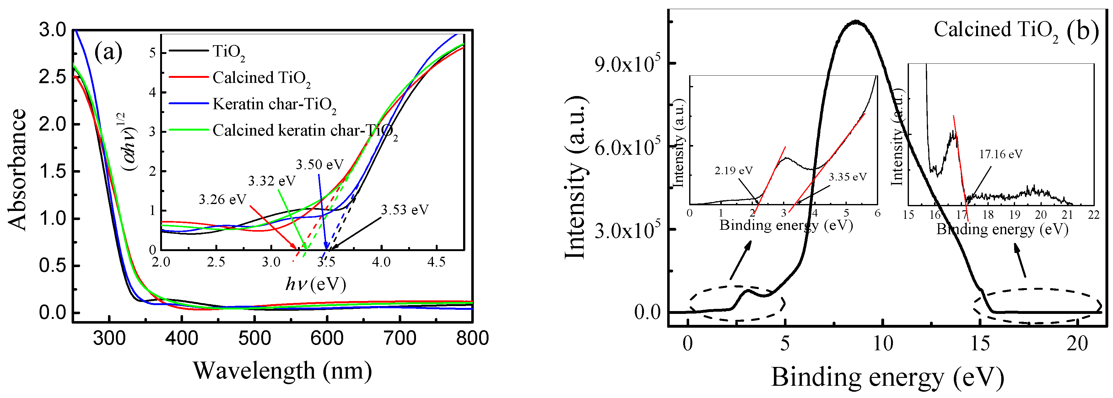
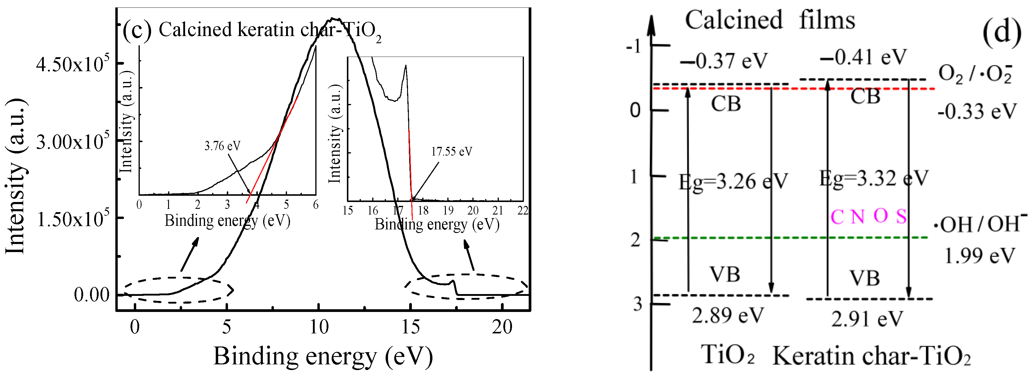
2.7. Energy Band Gap Structures

The transmission spectra inserted with the plots of (αhν)1/2 versus in the 200–800 nm range, the UPS spectra, and the corresponding band structures of the TiO2 films and keratin char-TiO2 composite films are illustrated in Figure 7. The transmittances for all the films sharply decreased at the light absorption edge around 300 nm. The excitation of electrons induced the strong absorption in UV region from its valence band to the conduction band of TiO2. After calcination, the absorption edges of the calcined TiO2 film and keratin char-TiO2 composite film were shifted towards longer wavelengths. This was attributed to the structure change from amorphous to anatase phase for both films, the C doping for the TiO2 film and the C, N, and S co-doping for the keratin char-TiO2 composite film [51]. All the films exhibited good transmittance in visible light wavebands.
The band gap energies of the TiO2 films and keratin char-TiO2 composite films were estimated to be 3.53 and 3.50 eV which were reduced to 3.26 and 3.32 eV after the calcination, respectively. The band gap of the calcined TiO2 film was very close to the theoretic value 3.2 eV of anatase TiO2. The narrowed band gap was ascribed to the crystallization of TiO2 under high-temperature conditions [20]. The C, N, and S co-doping could broaden the band gap of keratin char-TiO2 composite film. However, the band gap of rutile TiO2 modified wool powders was slightly reduced compared with the pure rutile TiO2 particles [30]. The difference in the band gaps between the keratin char-TiO2 composite film and TiO2 film might be attributed to their different structures, crystallite sizes, electron mobility abilities, and activation energies [52].
The cutoff energies of the calcinedTiO2 film and keratin char-TiO2 composite film were separately estimated to be 15.49 and 17.52 eV by extrapolating the straight portion of the UPS curve at high binding energy region to zero. It was demonstrated that the work function of semiconductors could be calculated by subtracting the cutoff energy from the photon energy of the He I light source (21.2 eV) [53]. Thus, the work functions of thecalcinedTiO2 film and calcined keratin char-TiO2 composite film were 5.71 and 3.68 eV with respect to the vacuum level. The Fermi energies of thecalcinedTiO2 film and calcined keratin char-TiO2 composite film were −5.71 and −3.68 eV under vacuum conditions, respectively. Moreover, the valence band energy was estimated by extrapolating the straight line of the UPS curve at the low binding energy region to zero, which was lower than its Fermi energy. The valence band energies versus vacuum level were respectively calculated to be 2.19 and 4.02 eV for thecalcinedTiO2 film and calcined keratin char-TiO2 composite film. The valence bands of the calcinedTiO2 film and calcined keratin char-TiO2 composite film were −7.90 and −7.70 eV with respect to vacuum level, respectively. Considering the band gaps obtained from Tauc’s plot, the corresponding conduction band energies were −4.64 eV for the calcinedTiO2 film and −4.38 eV for the calcined keratin char-TiO2 composite film with respect to the vacuum level. As a result, the valence band and conduction band energies were respectively3.40 and 0.14 eV for thecalcinedTiO2 film and 3.20 and −0.12 eV for the calcined keratin char-TiO2 compositefilm versus the normal hydrogen electrode (NHE).

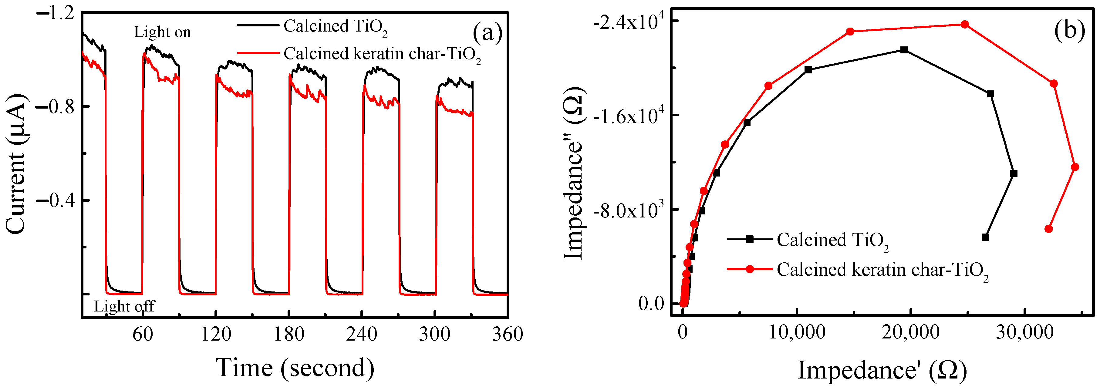
2.8. Separation Efficiency of Photogenerated Electron–Hole Pairs

The photocurrent-time curves and EIS plots of the calcined TiO2 film and calcined keratin char-TiO2 composite film are exhibited in Figure 8 to judge the separation and transfer efficiencies of photogenerated electron-hole pairs using the amperometric method. As the light turned on and off, the photocurrent responses were detected in both films which were derived from the photogenerated electron and hole separation. The photocurrent density of the calcined TiO2 film was larger than that of the calcined keratin char-TiO2 composite film. Hence, incorporating wool keratins into TiO2 might hinder the separation and transfer of photoinduced charge carriers in TiO2 [54]. As the light on/off cycle increased, the photocurrent intensity decreased slightly because of the recombination of photogenerated electron and hole pairs in the photo-response process [55].
The EIS Nyquist plots indicated that both the semicircle arcs of the calcined films were very close in the high-frequency region, implying there was no significant difference in the charge-transfer resistance for the calcined TiO2 film and calcined keratin char-TiO2 composite film [54]. However, in the low-frequency region, the calcined keratin char-TiO2 composite film’s arc radius was larger than the calcined TiO2 film, suggesting the diffusion process of photogenerated charge carriers was inhibited in the calcined keratin char-TiO2 composite film. The impedance of the calcined keratin char-TiO2 composite film was larger than that of the calcined TiO2 film. This was probably attributed to the fact that the calcined keratin char-TiO2 composite film had the elements of N and S, although the C content (20.89% in atomic conc.) of the calcined keratin char-TiO2 composite film was slightly larger than that (19.56% in atomic conc.) of the calcined TiO2 film.

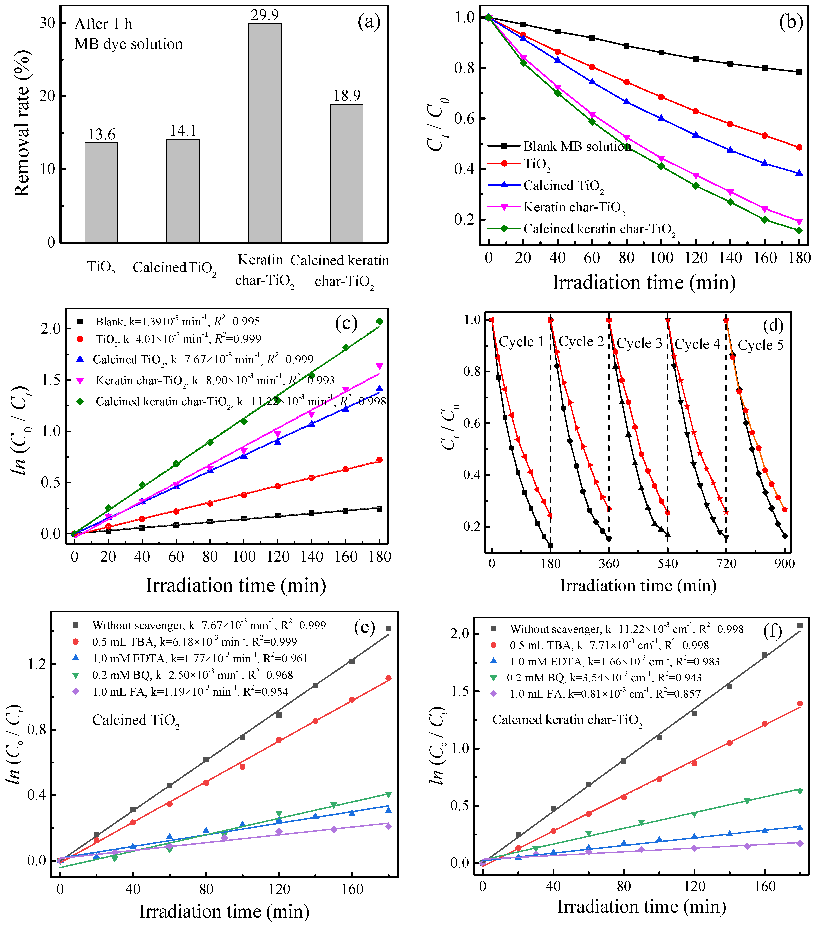
2.9. Photocatalysis Performance

The adsorption ability (in the dark), photocatalytic degradation, cycle stability, and trapping experiments of MB dye solutions by the TiO2 films and keratin char-TiO2 composite films under visible light irradiation are described in Figure 9. It was evident that after 1 h of adsorption in the dark, the removal rate of MB dye from the aqueous solution by the keratin char-TiO2 film (29.9%) was much larger than that of the TiO2 film (13.6%). The removal rate of MB dye by the calcined keratin char-TiO2 composite film was reduced to 18.9% but larger than that of the calcined TiO2 film (14.1%). As compared with the calcined TiO2 film, the strong adsorption ability of the calcined keratin char-TiO2 composite film towards the MB dye was verified by the following DFT theoretical calculations. The k value for the blank MB dye solution was calculated to be 1.39 × 10⁻³ min−1 (R2 = 0.995), indicating the visible light had a little effect on the photodegradation of the MB due to the photosensitization of MB molecules [56]. With respect to the uncalcined films, when wool keratin was doped with TiO2, after 180 min visible light illumination, the degradation rate and k value of the keratin char-TiO2 composite films increased from 51.4% and 4.01 × 10⁻³ min−1 (R2 = 0.999) to 80.6% and 8.90 × 10⁻³ min−1 (R2 = 0.993), respectively. This was probably because the wool keratin sulfhydryl group (-SH-) had a strong complexing property and promoted the contact between TiO2 and MB molecules [57]. After the films were calcinated, the k values of the calcined TiO2 film and calcined keratin char-TiO2 composite film separately increased to 7.67 × 10⁻³ min−1 (R2 = 0.999) and 11.22 × 10⁻³ min−1 (R2 = 0.998). It meant that the high-temperature treatment resulted in the incorporation of C, N, and S elements of wool keratin into TiO2 lattice and the crystallization of TiO2 as confirmed by XPS and XRD results. Thus the electron energy band structures and the hydrophilic abilities of the calcined TiO2 film and calcined keratin char-TiO2 composite film were changed. The separation and transfer of photogenerated electron and hole pairs were improved accordingly. It was confirmed that the non-metal element doping could introduce the O2 sites in TiO2 to mediate its valence band and reduce its band gap. At the same time, the catalyst density, the specific surface area, the concentration of valence surface oxygen, and the surface reaction sites increased to some extent, which further promoted the photocatalytic activity of TiO2 [12].
The photodegradation stability results indicated that after five successive MB photodegradation, the degradation rates decreased slightly from 75.7% to 73.4% for the calcined TiO2 film and from 87.4% to 83.6% for the calcined keratin char-TiO2 composite film. The long-term light irradiation might degrade the C-C bonds, decompose the protein compositions, and increase the carbon defects in the calcined keratin char-TiO2 composite film during the photocatalytic process [58]. Hence, the photocatalytic activities of both the calcined films were well maintained for the photodegradation of the MB solution under visible light irradiation.
To detect the reactive species of h+, 1O2, •OH, and •O2, the trapping experiments of the calcined films were conducted by adding the scavengers of EDTA, FA, TBA, and BQ in MB solutions under visible light, respectively. Obviously, after being added with EDTA, FA, TBA, and BQ individually, the k values decreased to different extents. Both the calcined films follow the same order: FA > EDTA > BQ > TBA, and thereby 1O2 played a decisive role in the MB photodegradation process. The k values were reduced to 1.19 × 10⁻³ min−1 (R2 = 0.954) and 0.81 × 10⁻³ min−1 (R2 = 0.857) for the calcined TiO2 film and calcined keratin char-TiO2 composite film, respectively. At the same time, h+, •O2 and •OH also affected the MB photodegradation process. The reactive order of radical species was not in agreement with the previous studies [31]. Therefore, the doping of wool keratin had no influence on the radical species of calcined TiO2 film in the MB photodegradation process under visible light irradiation.

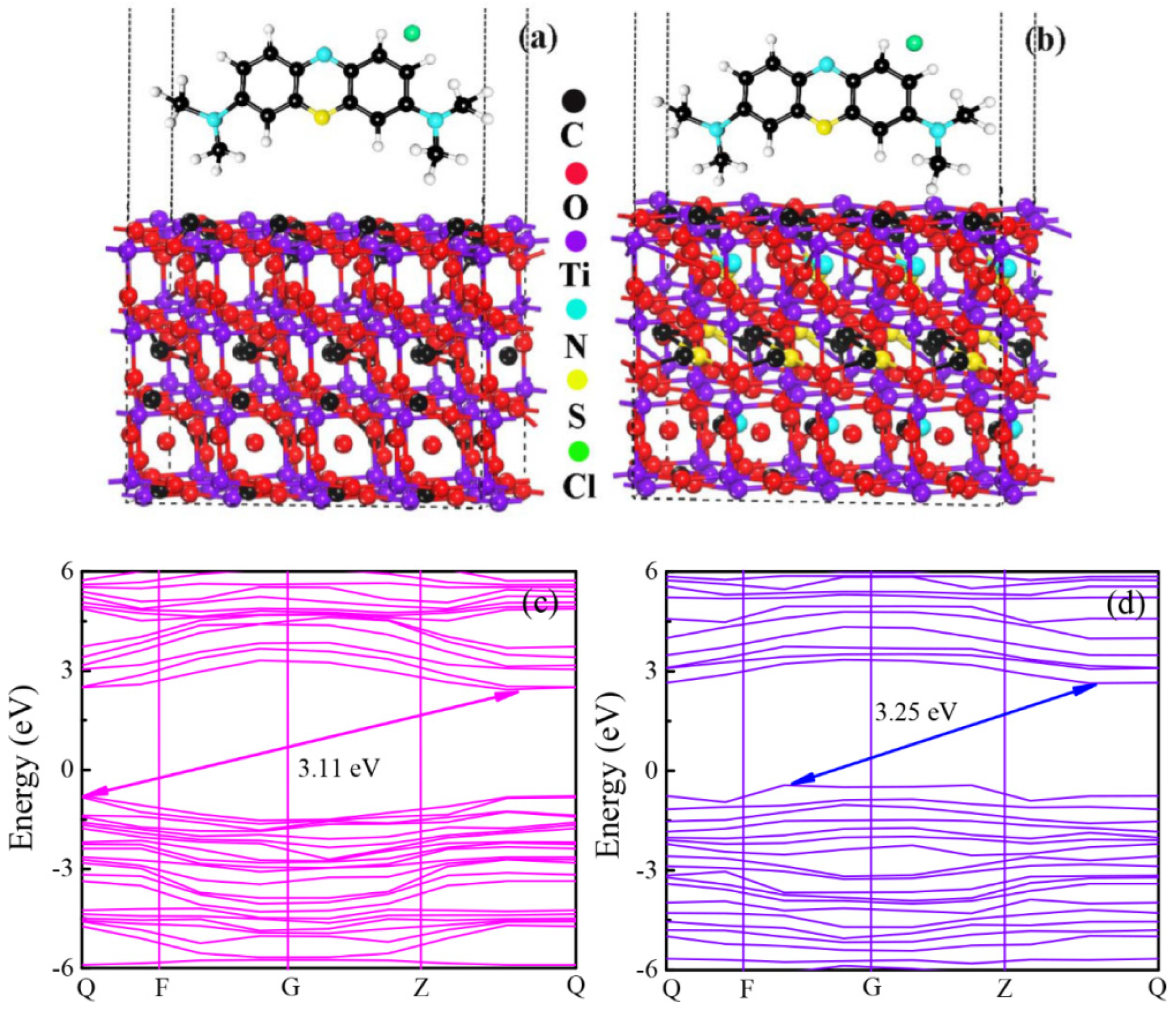
2.10. DFT Theoretical Calculations

The schematic constructions of adsorption energy and energy band structures for the calcined TiO2 film and calcined keratinchar-TiO2 composite film were simulated using the DFT calculations, as displayed in Figure 10. As shown in Figure 10a,b, the relaxed atom structures of an MB molecule were separately adsorbed on the calcined TiO2 (C-doped TiO2) and calcined keratin char-TiO2 (C, N and S co-doped TiO2). According to Equation (5), the Eads values were calculated to be −0.514 eV for the C-doped TiO2 and −0.891 eV for the C, N, and S co-doped TiO2 [59]. The higher Eads of −0.891 eV implied that the adsorption of the MB molecules on the calcined keratin char-TiO2 composite film occurred more easily. Thus, the co-doping of C, N, and S elements of keratin into anatase TiO2 was a benefit for the adsorption of MB on the calcined keratin char-TiO2 composite film. This was a vital process for photocatalytic degradation. Although the calcined keratin char-TiO2 composite film’s band gap increased slightly compared to the calcined TiO2 film, the photocatalytic degradation performance of the calcined keratin char-TiO2 composite film did not become deteriorated. The strong adsorption of MB on the composite film played a privileged role in the MB photocatalytic degradation process [60].
The energy band structures along the high symmetry directions were calculated to investigate the underlying electronic properties of calcined TiO2 film and calcined keratin char-TiO2 composite film. As shown in Figure 10c,d, because the calculated conduction band minima and valence band maxima for both the calcined films were located at different high symmetry points, they had indirect band gaps. Generally, the photogenerated charge carriers cannot recombine directly for the indirect band gap semiconductors, which is favorable for the photocatalytic reaction [61]. The calculated band gaps were 3.11 and 3.25 eV for the calcined TiO2 film and calcined keratin char-TiO2 composite film, which were slightly smaller than the experimental results as shown in Figure 7d (3.26 eV for the calcined TiO2 film and 3.32 eV for the calcined keratin char-TiO2 composite film), respectively. Therefore, it was concluded that the band gap of the calcined keratin char-TiO2 composite film increased when the C, N, and S elements of wool keratins were doped into anatase TiO2.

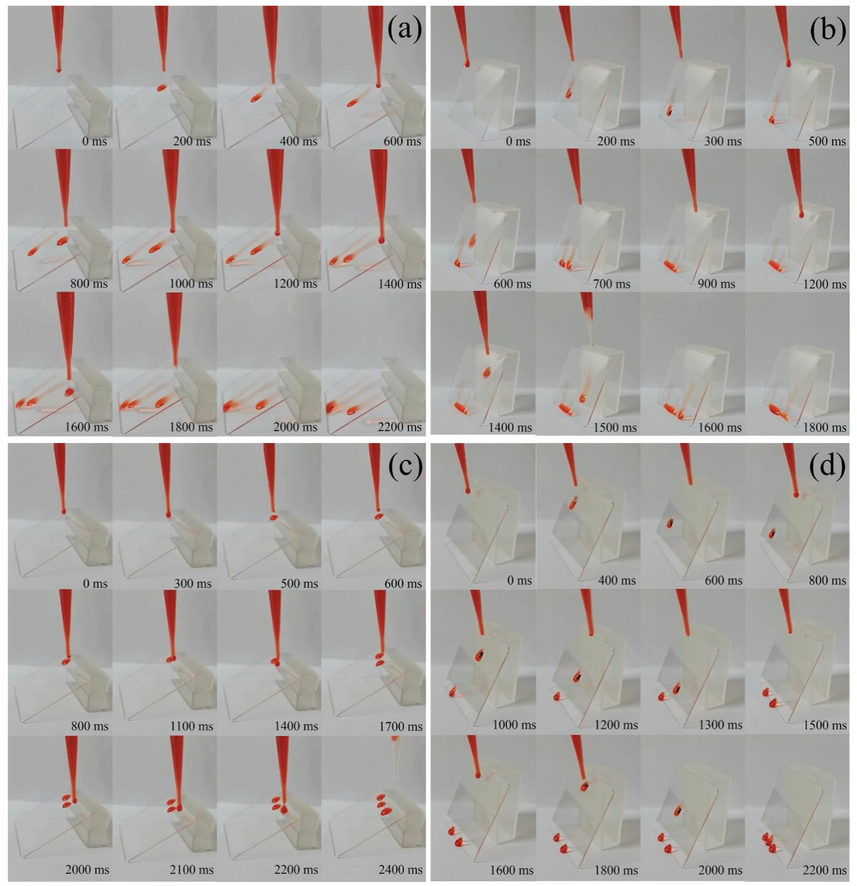
2.11. Hydrophobic Behaviors

The time-sequence photographs of water droplets (Congo red was used for better showing) sliding process on the surfaces of the calcined TiO2 film and calcined keratinchar-TiO2 composite film at different sliding angles were shown in Figure 11. It was found that no matter what the film tilt angle was, the water droplets could spread out and slip off on the calcined TiO2 film leaving their marks (Figure 11a,b). On the contrary, the water droplets were adhered to the surface of the calcined keratinchar-TiO2 composite film and were about to roll off when the film tilt angle was smaller than 30°.Once the inclination angle of the composite film was larger than 45°, the water droplets quickly rolled off from its surface without any residual liquid left. This was due to the large water contact angle and rough surface of the calcined keratin char-TiO2 composite film [62]. Hence, the C, N, and S elements co-doping with TiO2 could significantly improve the hydrophobicity of the calcined keratinchar-TiO2 composite film.
It is known that the hydrophobic self-cleaning film cannot be resistant to acid and alkali corrosion, resulting in poor waterproof and decontamination performance [63]. Here, the hydrophobicity of the films was further assessed by acid and base immersion tests, as illustrated in Figure 12. The calcined TiO2 film and calcined keratinchar-TiO2 composite film were separately immersed in 10% HCl and 10% alkaline aqueous solution at 30 °C for 24 h and then washed with deionized water to remove the residual chemicals. No change of water droplets state was observed on both acid- and alkali-treated keratinchar-TiO2 composite films, exhibiting better corrosion resistance. However, the hydrophilicity of the alkali-treated TiO2 film was improved to some degree. This was caused by the increased surface free energy resultant from OH groups and small water contact angle [64].

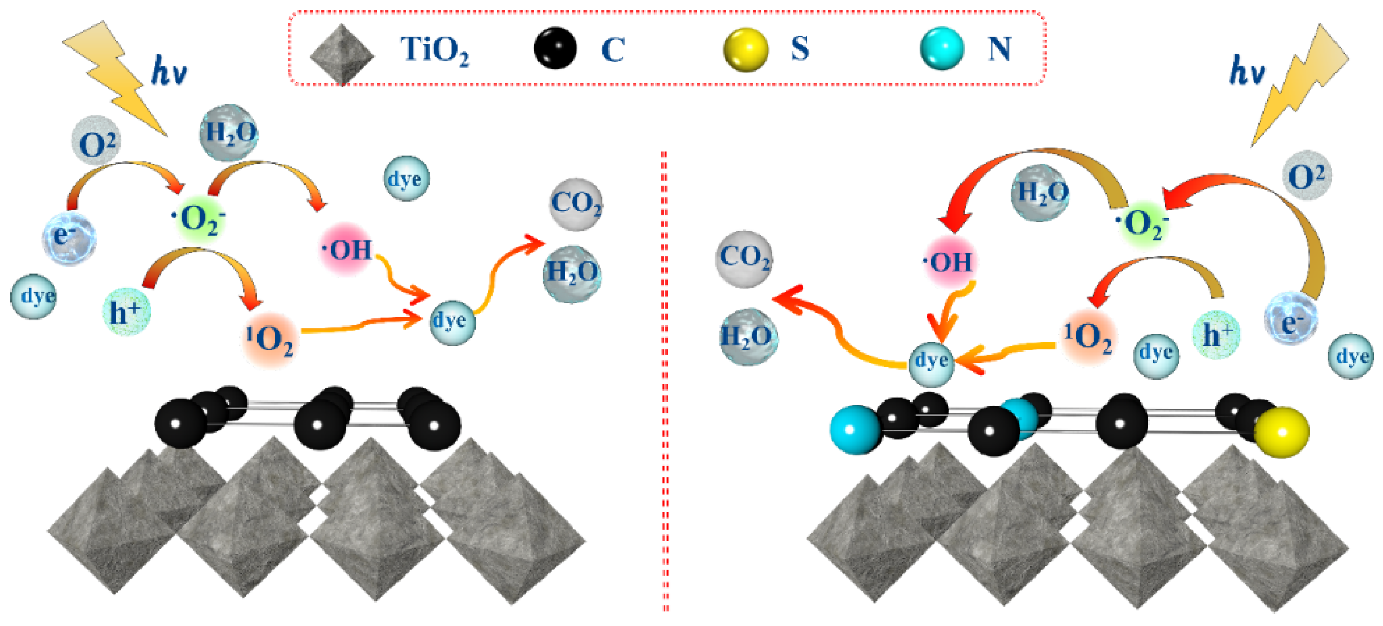
2.12. Photocatalytic Reaction Mechanism

Based on the above characterization analysis and DFT calculations, the photocatalytic mechanisms for the MB photodegradation by the calcined TiO2 film and calcined keratin char-TiO2 composite film are explicated in Figure 13. The atom mass ratios (in percent) of C1s to Ti2p were 19.56:24.34 for the calcined TiO2 film and 22.89:23.00 for the calcined keratin char-TiO2 composite film. Thus, the amount of keratin char layer was less than the amount of TiO2; a certain amount of TiO2 nanoparticles could be exposed to the air in both films. For both the calcined films, the valence band potentials were more positive than the redox potential of OH/•OH (1.99 eV vs. NHE) couples, meanwhile, the conduction band potentials were more negative than the redox potential of O2/•O2 (−0.33 eV vs. NHE) couples. Thus, the photogenerated holes could oxidize H2O to generate OH radicals, meanwhile, the photogenerated electrons could reduce dissolved O2 to produce O2 radicals. Because the absolute value of the adsorption energy (−0.891 eV) of calcined keratin char-TiO2 composite film was larger than that (−0.514 eV) of the calcined TiO2 film, the MB dye molecules were closely adsorbed on the calcined keratin char-TiO2 composite film. The photoinduced active species like 1O2, h+, •O2 and •OH could easily/quickly react with the dye molecules. Thus, the calcined keratinchar-TiO2 composite film containing N and S could result in enhanced photocatalytic activities. Due to the presence of carbon layer in both films, as demonstrated by TEM and XPS analyses, the photogenerated electrons were prone to transfer to the carbon layer. In contrast, the photogenerated holes would stay on TiO2.Hence, the recombination of photogenerated electron and hole pairs in both the calcined films could be effectively inhibited. As confirmed by the trapping experiments, the photogenerated electrons could react with dissolved O2 to produce •O2 radicals, which further reacted with the photogenerated h+ to generate 1O2 radicals. The formation rate of 1O2 radical was faster than that of OH radical because the reaction route of 1O2 was shorter than that of OH. Thus, the main active species was 1O2 radicals in the MB photodegradation process. In addition, the calcined TiO2 film and calcined keratin char-TiO2 composite film had many meso- and micro-pores as confirmed by FESEM, which might facilitate the adsorption of MB dyes molecules. Hence, the adsorption capacities for both films were a benefit for the removal of dyes from the solution.

3. Experimental Section

3.1. Materials and Reagents

Wool fibers were obtained from a local textile mill, and the fineness was in the range from 21.6 to 23.0 μm. All chemical reagents used in the present work were analytical grade, including absolute ethanol (C2H6O), petroleum ether (CAS No.8032-32-4), sodium pyrosulfite (Na2S2O5), urea (CH4N2O), sodium dodecyl sulfonate (SDS, C12H25SO4Na), sulphuric acid (H2SO4), hydrogen peroxide (H2O2), 3-aminopropyltrimethoxysilane (APES, C6H17NO3Si), titanium isopropoxide (TTIP, C12H28O4Ti), acetic acid (CH3COOH), isopropyl alcohol (IPA, (CH3)2CHOH), methylene blue (MB, C16H18ClN3S), tert-butyl alcohol (TBA, C4H10O), benzoquinone (BQ, C6H4O2), furfuryl alcohol (FA, C5H6O2), and ethylenediaminetetraacetic acid (EDTA, C10H16N2O8). Deionized water was applied for the preparation of the solutions.

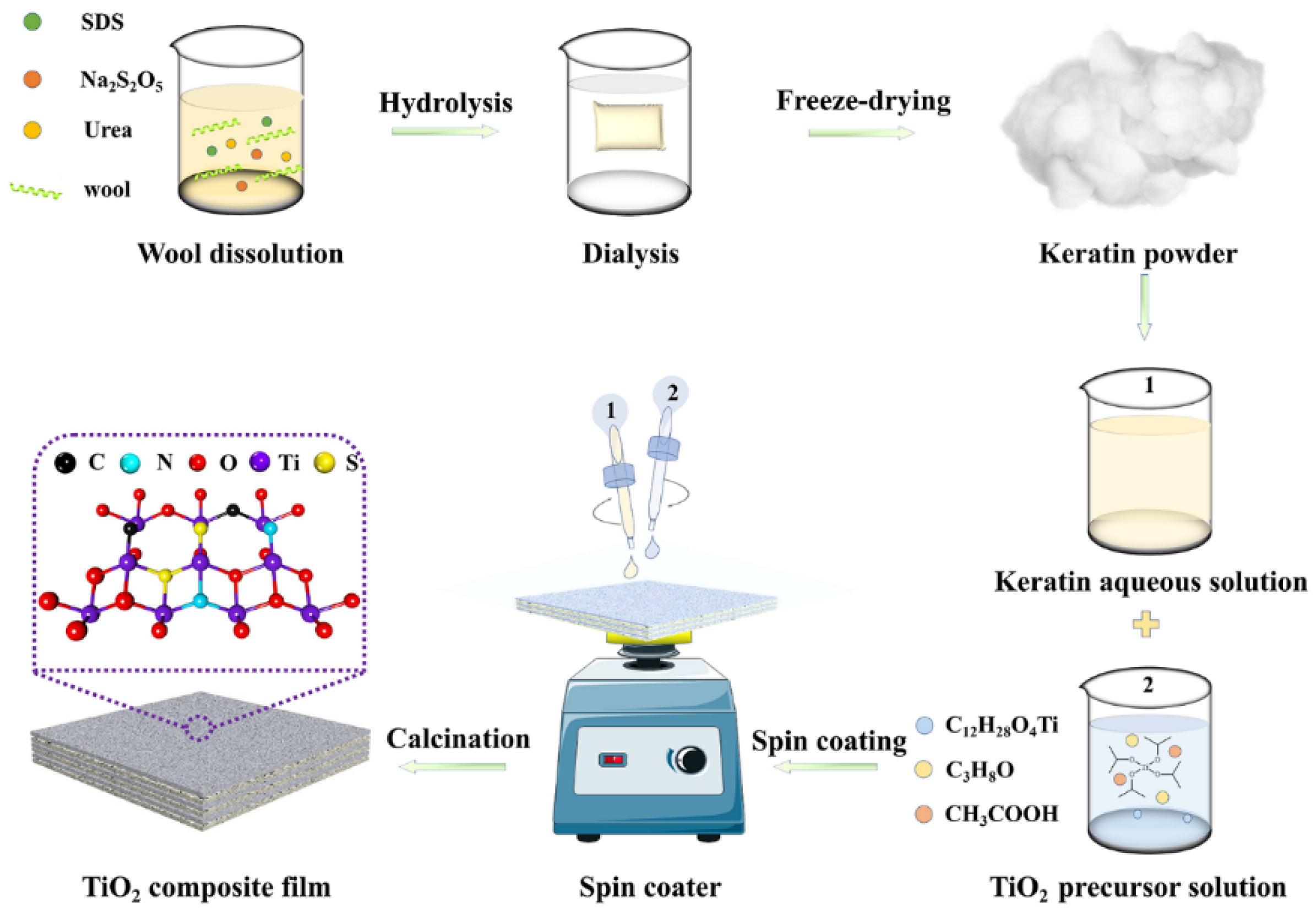
3.2. Preparation of Keratin char-TiO2 Composite Films

The procedure for the preparation of keratin char-TiO2 composite films is shown in Figure 14. Firstly, wool keratins were obtained from cleaned wool fibers using the chemical reduction technique. Next, the wool keratin-TiO2 composite films were prepared by alternatively spin-coating of keratin aqueous solution and TiO2 precursor solution on quartz glass slides. Lastly, the wool keratin-TiO2 composite films were calcined at 400 °C in an air environment to obtain the keratin char-TiO2 composite films.

3.2.1. Extraction of Wool Keratins

The as-obtained wool fibers were first degreased on a Soxhlet apparatus using petroleum ether as the solvent to remove the lipids and impurities of wools at 80 °C for 12 h [65], then successive washed with absolute ethanol and deionized water, and lastly dried at 60 °C overnight. The degreased wool fibers (0.1 g) were cut into snippets with less than 5 mm length and then immersed in 10 mL of mixture solution containing0.5 M Na2S2O5, 8 M urea, and 0.2 M SDS based on a chemical reduction method [66]. The mixture solution was heated to 100 °C and treated at a constant temperature for 2 h under continuous magnetic stirring. After that, 40 mL deionized water was poured into the mixture solution, filtered with a400-mesh stainless-steel mesh screen with a diameter of 0.037 mm to remove the insoluble substances. The filtrate was dialyzed against deionized water using a cellulose tube with a cutoff of 3500 Da for 3 days at room temperature. During the dialysis procedure, the deionized water was changed every 6 h. The resultant aqueous solution was condensed with a lyophilizer to obtain the pristine wool keratin powders.

3.2.2. Spin-Coating and Calcinations of Wool Keratin-TiO2 Composite Films

The wool keratin-TiO2 composite films were deposited on quartz glass slides based on a sol-gel spin-coating technique [67]. Prior to spin-coating, the glass slides were cleaned with piranha solution (H2O2:H2SO4 = 1:3 in volumes) to remove any organic contaminants and native oxide layer on the substrate [68]. A thin layer of APES was first spin-coated on the clear glass slide with 2 vol% APES absolute ethanol solution to improve the binding ability between wool keratin and glass substrate. Next, 0.142 g TTIP and 0.2 mL acetic acid were slowly added into 100 mL isopropyl alcohol under stirring to obtain the TTIP precursor solution. Meanwhile, 3 mg of wool keratin powders was added in 10 mL deionized water to obtain the keratin solution, which was spin-coated on the glass slide at a speed of 4000 rpm for 30 s. The glass slide was immediately heated at 80 °C for 1 min. The TTIP precursor solution was subsequently spin-coated on the keratin-coated slide at 4000 rpm for 30 s twice and then treated at 100 °C for 10 min. The quartz glass slide was alternately spin-coated with wool keratin and TTIP precursor solutions for 50 cycles to obtain the wool keratin-TiO2 composite films. The TiO2 films were also fabricated by the spin-coating method only with the TTIP precursor solution. Lastly, the spin-coated quartz glass slides were subjected to annealing at 400 °C for 1 h and cooled down naturally.

3.3. Characterization Methods

According to the Bradford protein assay method [69], the molecular weight distribution of as-prepared wool keratins was determined on the Mini-Protean system by the SDS–polyacrylamide gel electrophoresis (PAGE). The wool keratin powders were dissolved in a buffer solution containing Tris/HCl (1.25 mM, pH 6.8), SDS (500 mg), bromophenol blue (25 mg), and glycerin (2.5 mL) to form a 6 mg/mL keratin gel solution. The resultant gel solution was running at a constant voltage of 180 V. The molecular weights of keratin proteins could be calibrated by Coomassie Brilliant Blue G250 staining using a kit of molecular weight markers (Shanghai Institute of Biochemical Cell, Chinese Academy of Sciences, Shanghai, China) containing phosphorylase-b (97.4 kDa), serum albumin (66.2 kDa), actin (43 kDa), carbonic anhydrase (31 kDa), trypsin inhibitor (20.1 kDa) and R-lactalbumin (14.4 kDa).
The morphologies of as-prepared films were examined on a Quanta-450-FEG+X-MAX50 field emission scanning electron microscope (FESEM, FEI Company, Hillsboro, OR, USA). The specimens were sprayed with conductive gold coating under vacuum prior to testing.
The surface roughness of the films was investigated on a Laser electron microscope (Carl Zeiss AG, Oberkochen, Germany).
The crystal structures of the films were analyzed on a 7000S X-ray diffractometer (Shimazu Corp., Kyoto, Japan) operated at 40 kV and 30 mA at a scanning rate of 8°/min. The Cu Kα1 X-ray source (λ = 0.154056 nm) was used. The crystallinity size (D) was calculated according to the Scherrer Equation (1) [70] as below.
D = /βcosθ,
where k, λ, β and θ were a constant (0.89), X-ray wavelength, full width at half maximum (FWHM), and Bragg angle, respectively.
The microstructures of the calcined films were observed on a JEM-3010 transmission electron microscope (TEM, JEOL Ltd., Tokyo, Japan).
The static water contact angleof the films was conducted on an OCA25 contact angle meter (Data Physics Instruments, Filderstadt, Germany) according to the drop method.
The chemical bonding states of the films were carried out on an Axis Ultra electron spectrometer (Kratos Analytical Ltd., Manchester, UK) operated at 10 kV and 10 mA at the vacuum below 10−8 Torr. The monochromatic Al Kα (1486.68 eV) radiation was used, and the binding energies were calibrated through the 284.8 eV C1s peak.
The diffuse reflectance spectra of the films were recorded on a Lambda 950 spectrophotometer (PerkinElmer Inc., Waltham, MA, USA) equipped with a 150 mm integrating sphere. The barium sulfate was applied to calibrate the 100% reflectance. The band gap energy (Eg) was deduced from the intersection of the extrapolation of (αhv)1/2 versus hv according to the Tauc Equation (2) [38] as below:
A(hvEg)n/2 = αhv,
where α was the absorption coefficient, ν was the light frequency, h was the Planck constant, A was a constant which was determined by the nature of allowed transition (n = 1/2 for direct and 2 for indirect).
The calcined films’ ultraviolet photoelectron spectroscopy (UPS) was performed on the Escalab 250 Xi UV photoelectron spectroscope (Thermo Fisher Scientific Inc., Waltham, MA, USA).
The photocurrent response curves and electrochemical impedance spectroscopy (EIS) Nyquist plots of the calcined films were measured on a CHI760E electrochemical workstation (Shanghai Chenhua Instrument Co., Ltd. Shanghai, China) based on the three-electrode system. A 300 W Xenon lamp was used to simulate visible lights along with a 420 nm cutoff filter. The Pt foil and saturated calomel electrode (SCE) were used as the counter and reference electrodes. The working electrode was prepared by spin-coating wool keratin and/or TTIP precursor solutions on an indium-tin-oxide (ITO) glass substrate with a size of 2 × 1 cm2. The photocurrent-time curves were collected under visible lights by turning on/off cycles at 0.5 V vs. SCE. The electrolyte was 0.5 M Na2SO4 aqueous solution at the pH value of 7, and the experimental equipment ran for 30 s firstly, and then each illumination time was 30 s. The frequency for EIS measurements was from 0.1 to 100,000 Hz at an alternating current voltage amplitude of 5 mV under open-circuit conditions.

3.4. Measurements of Photocatalytic Properties

The photocatalytic properties of the as-prepared films were assessed by measuring the photodegradation of model MB dye under visible light irradiation. In a typical experiment, the film specimen (4 × 4 cm2) was put in a glass petri dish (ϕ = 90 mm) containing 50 mL of 1.0 mg/L MB solution. The pH of the MB solution was 6.8. Prior to illumination, the dye solution with the film was placed in the dark for 60 min to reach an adsorption−desorption equilibrium. After that, a 30 W LED lamp was applied on the dye solution, and the illuminance of the light was 45,000 Lux. At a given time interval t, 3 mL solution was extracted from the dye solution. The absorbance At was recorded on a VIS-7220 visible light spectroscope (Beijing Beifen-Ruili Analytical Instrument Co. Ltd., Beijing, China) at 664 nm. The concentration Ct was calculated according to the MB calibration curve (At = 0.0107 + 0.1767Ct, R2 = 0.99). The degradation rate D (%) was calculated according to Equation (3) as below:
D (%) = (1 − Ct/C0) × 100%,
where C0 and Ct were respectively the MB concentration at the initial time and time t. To quantitatively identify the photodegradation of MB solution, the reaction kinetic data were fitted based on the Langmuir–Hinshelwood model [71]. The pseudo-first-order apparent rate constant k (min−1) was calculated by Equation (4) as below:
ln(C0/Ct) = kt,
In addition, the oxidized MB dye solution was replaced by the fresh MB solution, and the cycle photodegradation of MB solution was measured under the same visible light irradiation condition. The active species of h+, 1O2, •OH, and •O2 in the photocatalytic solutions were identified by adding 1.0 mM EDTA, 1.0 mL FA [72], 0.5 mL TBA, and 0.2 mM BQ [73] as the scavengers, respectively.

3.5. Theoretical Calculation Method

The DFT calculations were implemented using the Vienna Ab Initio Package [74,75] program based on the Perdew–Burke–Ernzerhof generalized gradient approximation [76]. The ionic cores were described by the projected augmented wave potentials [77,78], and the valence electrons were considered. For the plane-wave basis set, an energy cutoff of 450 eV was used. The Gaussian smearing techniquewith0.05 eV width was applied to optimize the partial occupancies of the Kohn−Sham orbitals. Provided that the energy change was less than 10−4 eV, self-consistent electronic energy was realized. When the force change was below 0.05 eV/Å, the geometry optimization was supposed to be convergent. The empirical dispersion correction methodology [79] was employed to explicate the dispersion interactions.
The Brillouin zone sampling with a 10 × 10 × 4 Monkhorst-Pack k-point grid was used to optimize the equilibrium lattice constants of TiO2 unit cell. A super cell Graphene model was constructed in the x and y directions. The 3 × 3 × 1 Monkhorst–Pack k-point grid was used for the Brillouin zone sampling for the C, N and S atoms doping in the super cell TiO2 structure in the structural optimization process. Thus, the adsorption energy(Eads) could be calculated according to Equation (5) as below:
Eads = Ead/sub − Ead − Esub,
where Ead/sub was the total energies of the optimized adsorbate/substrate system, Ead was the adsorbate energy of the structure, and Esub was the energy of the clean substrate.

4. Conclusions

The hydrophobic self-cleaning keratin char-TiO2 composite films were made from the calcination of keratin-TiO2 films for the photocatalytic degradation of dye pollutants. The incorporation of TiO2 precursors in the wool keratin film led to the formation of anatase TiO2 nanoparticles after calcination. The water contact angle and band gap of the calcined keratin char-TiO2 composite film were greater than the calcinated TiO2 film. Although the separation of photogenerated charge carriers was inhibited, the calcined keratin char-TiO2 composite film exhibited better photocatalytic performance in the MB degradation process and good hydrophobic behaviors to shield off water droplets. Both experiments and DFT calculations demonstrated that the high photocatalytic properties of the calcined keratin char-TiO2 composite film were mainly ascribed to its rough surface, particular porous structure, large water contact angle, and high adsorption energy, which were helpful for the contact of organic compounds with the composite film. 1O2 radicals were the dominant reactive species. Overall, the calcined keratin char-TiO2 composite film obtained could be used in the photocatalysis field.

Author Contributions

H.Z. conceptualized, designed, and administered the experiments. J.Z. contributed to the synthesis and characterization of materials. W.L., L.Y. and H.W. helped in collecting and analyzing data. N.M. helped to revise the grammar and gave conceptual advice. All authors analyzed and discussed the data. J.Z. and H.Z. wrote the manuscript. All authors have read and agreed to the published version of the manuscript.

Funding

This research was funded by the National Natural Science Foundation of China (No. 51873169), the International Science and Technology Cooperation Project of Shaanxi Province (2020KW-069), and the Sanqin Scholar Foundation (2017).

Conflicts of Interest

The authors declare no conflict of interest.

References

  1. Demirci, S.; Dikici, T.; Yurddaskal, M.; Gultekind, S.; Toparli, M.; Celik, E. Synthesis and characterization of Ag doped TiO2 heterojunction films and their photocatalytic performances. Appl. Surf. Sci. 2016, 390, 591–601. [Google Scholar] [CrossRef]
  2. Fang, W.F.; Xin, M.Y.; Zhang, J.L. Modifications on reduced titanium dioxide photocatalysts: A review. J. Photochem. Photobiol. C 2017, 32, 21–39. [Google Scholar] [CrossRef]
  3. Tung, W.S.; Daoud, W.A. Photocatalytic formulations for protein fibers: Experimental analysis of the effect of preparation on compatibility and photocatalytic activities. J. Colloid Interface Sci. 2008, 326, 283–288. [Google Scholar] [CrossRef]
  4. Komaraiah, D.; Radha, E.; Sivakumar, J.; Reddy, M.V.R.; Sayanna, R. Structural, optical properties and photocatalytic activity of Fe3+ doped TiO2 thin films deposited by sol-gel spin coating. Surf. Interfaces 2019, 17, 100368. [Google Scholar] [CrossRef]
  5. Perez, J.A.B.; Courel, M.; Pal, M.; Delgado, F.P.; Mathews, N.R. Effect of ytterbium doping concentration on structural, optical and photocatalytic properties of TiO2 thin films. Ceram. Int. 2017, 43, 15777–15784. [Google Scholar] [CrossRef]
  6. Anas, M.; Han, D.S.; Mahmoud, K.; Park, H.; Abdel, -W.A. Photocatalytic degradation of organic dye using titanium dioxide modified with metal and non-metal deposition. Mat. Sci. Semicon. Proc. 2016, 41, 209–218. [Google Scholar] [CrossRef]
  7. Datcu, A.; Mendoza, M.L.; del Pino, A.P.; Logofatu, C.; Luculescu, C.; Gyorgy, E. UV-visible light induced photocatalytic activity of TiO2/graphene oxide nanocomposite coatings. Catal. Today 2019, 321, 81–86. [Google Scholar] [CrossRef]
  8. Pant, B.; Saud, P.S.; Park, M.; Park, S.J.; Kim, H.Y. General one-pot strategy to prepare Ag-TiO2 decorated reduced graphene oxide nanocomposites for chemical and biological disinfectant. J. Alloys Compd. 2016, 671, 51–59. [Google Scholar] [CrossRef]
  9. Pant, B.; Pant, H.; Barakat, N.A.M.; Park, M.; Han, T.H.; Lim, B.H.; Kim, H.Y. Incorporation of cadmium sulfide nanoparticles on the cadmium titanate nanofibers for enhanced organic dye degradation and hydrogen release. Ceram. Int. 2014, 40, 1553–1559. [Google Scholar] [CrossRef]
  10. Basavarajappa, P.S.; Patil, S.B.; Ganganagappa, N.; Reddy, K.R.; Raghu, A.V.; Reddy, C.V. Recent progress in metal-doped TiO2, non-metal doped/codoped TiO2 and TiO2 nanostructured hybrids for enhanced photocatalysis. Int. J. Hydrogen Energy 2020, 45, 7764–7778. [Google Scholar] [CrossRef]
  11. Nasr, M.; Eid, C.; Habchi, R.; Miele, P.; Bechelany, M. Recent progress on titanium dioxide nanomaterials for photocatalytic applications. Chemsuschem 2018, 11, 3023–3047. [Google Scholar] [CrossRef]
  12. Nasirian, M.; Lin, Y.P.; Bustillo-Lecompte, C.F.; Mehrvar, M. Enhancement of photocatalytic activity of titanium dioxide using non-metal doping methods under visible light: A review. Int. J. Environ. Sci. Technol. 2018, 15, 2009–2032. [Google Scholar] [CrossRef]
  13. El, N.A.; Helmy, E.T.; Gomaa, E.A.; Eldafrawy, S.; Mousac, M. Photocatalytic and biological activities of undoped and doped TiO2 prepared by green method for water treatment. J. Environ. Chem. Eng. 2019, 7, 103385. [Google Scholar]
  14. Zhang, G.Z.; Teng, F.; Wang, Y.Q.; Zhang, P.; Gong, C.S.; Chen, L.L.; Zhao, C.H.; Xie, E.Q. Preparation of carbon-TiO2 nanocomposites by a hydrothermal method and their enhanced photocatalytic activity. RSC Adv. 2013, 3, 24644–24649. [Google Scholar] [CrossRef]
  15. Kisch, H.; Sakthivel, S.; Janczarek, M.; Mitoraj, D. A low-band gap, nitrogen-modified titania visible-light photocatalyst. J. Phys. Chem. C 2007, 111, 11445–11449. [Google Scholar] [CrossRef]
  16. Ananpattarachai, J.; Kajitvichyanukul, P.; Seraphin, S. Visible light absorption ability and photocatalytic oxidation activity of various interstitial N-doped TiO2 prepared from different nitrogen dopants. J. Hazard Mater. 2009, 168, 253–261. [Google Scholar] [CrossRef] [PubMed]
  17. Pandiyan, R.; Delegan, N.; Dirany, A.; Drogui, P.; El, K.M.A. Probing the electronic surface properties and bandgap narrowing of in-situ N, W and (W, N) doped magnetron-sputtered TiO2 films intended for electro-photocatalytic applications. J. Phys. Chem. 2016, 120, 631–638. [Google Scholar] [CrossRef]
  18. Fan, M.N.; Lin, Z.H.; Zhang, P.; Ma, X.D.; Wu, K.P.; Liu, M.L.; Xiong, X.H. Synergistic effect of nitrogen and sulfur dual-doping endows TiO2 with exceptional sodium storage performance. Adv. Energy Mater. 2021, 11, 2003037. [Google Scholar] [CrossRef]
  19. Khan, M.I.; KBhatti, A.; Qindeel, R.; Althobaiti, H.S.; Alonizan, N. Structural, electrical and optical properties of multilayer TiO2 thin films deposited by sol-gel spin coating. Results Phys. 2017, 7, 1437–1439. [Google Scholar] [CrossRef]
  20. Dahnoun, M.; Attaf, A.; Saidi, H.; Benatia, R.; Yahia, A.; Khelifi, C.; Saadi, A.; Attaf, N.; Ezzaouia, H.; Guerbous, L. High transparent titanium dioxide-anatase thin films deposited by spin coating technique: Effect of annealing temperature. J. Nanoelectron. Optoelectron. 2018, 13, 1359–1365. [Google Scholar] [CrossRef]
  21. Rajendra, K.; Senthil, K.V.; Anitha, R.K. Synthesis and characterization of immobilized activated carbon doped TiO2 thin films. Optik 2014, 125, 1993–1996. [Google Scholar] [CrossRef]
  22. Li, J.X.; Chen, Z.; Fang, J.F.; Yang, Q.; Yang, X.R.; Zhao, W.; Zhou, D.T.; Qian, X.X.; Liu, C.X.; Shao, J.Z. Facile synthesis of TiO2 film on glass for the photocatalytic removal of rhodamine B and tetracycline hydrochloride. Mater. Express 2019, 9, 437–443. [Google Scholar] [CrossRef]
  23. Varshney, G.; Kanel, S.R.; Kempisty, D.M.; Varshney, V.; Agrawal, A.; Sahle-Demessie, E.; Varma, R.S.; Nadagouda, M.N. Nanoscale TiO2 films and their application in remediation of organic pollutants. Coordin. Chem. Rev. 2016, 306, 43–64. [Google Scholar] [CrossRef]
  24. Breeson, A.C.; Sankar, G.; Goh, G.K.L.; Palgrave, R.G. Rutile to anatase phase transition induced by N doping in highly oriented TiO2 films. Phys. Chem. Chem. Phys. 2016, 18, 24722–24728. [Google Scholar] [CrossRef] [PubMed]
  25. Shavandi, A.; Carne, A.; Bekhit, A.A.; Bekhit, A.E.A. An improved method for solubilisation of wool keratin using peracetic acid. J. Environ. Chem. Eng. 2017, 5, 1977–1984. [Google Scholar] [CrossRef]
  26. Shavandi, A.; Silva, T.H.; Bekhit, A.A.; Bekhit, A.E. Keratin: Dissolution, extraction and biomedical application. Biomater. Sci. 2017, 5, 1699–1735. [Google Scholar] [CrossRef] [PubMed] [Green Version]
  27. He, J.H.; Xu, D.; Li, J.Y.; Li, L.F.; Li, W.B.; Cui, W.G.; Liu, K.S. Highly efficient extraction of large molecular-weight keratin from wool in a water/ethanol co-solvent. Text Res. J. 2019, 90, 1084–1093. [Google Scholar] [CrossRef]
  28. Wang, J.; Li, R.; Ma, J.H.; Jian, Y.K.; Che, J.N. Extracting keratin from wool by using L-cysteine. Green Chem. 2016, 18, 476–481. [Google Scholar] [CrossRef]
  29. Rajabinejad, H.; Zoccola, M.; Patrucco, A.; Montarsolo, A.; Rovero, G.; Tonin, C. Physicochemical properties of keratin extracted from wool by various methods. Text. Res. J. 2018, 8, 2415–2424. [Google Scholar] [CrossRef]
  30. Zhang, H.; Wang, D.; Han, Y.; Tang, Q.; Wu, H.L.; Mao, N.T. High photoactivity rutile-type TiO2 particles co-doped with multiple elements under visible light irradiation. Mater. Res. Express 2018, 5, 105015. [Google Scholar] [CrossRef] [Green Version]
  31. Gu, H.S.; Zhang, H.; Zhang, X.Y.; Guo, Y.N.; Yang, L.M.; Wu, H.L.; Mao, N.T. Photocatalytic properties of core–shell structured wool-TiO2 hybrid composite powders. Catalysts 2021, 11, 12. [Google Scholar] [CrossRef]
  32. Ruzgar, D.G.; Kurtoglu, S.A.; Bhullar, S.K. A study on extraction and characterization of keratin films and nanofibers from waste wool fiber. J. Nat. Fibers 2020, 17, 427–436. [Google Scholar] [CrossRef]
  33. Villanueva, M.E.; Puca, M.; Bravo, J.P.; Bafico, J.; Orto, V.C.D.; Copello, G.J. Dual adsorbent-photocatalytic keratin-TiO2 nanocomposite for trimethoprim removal from wastewater. J. Chem. 2020, 44, 10964–10972. [Google Scholar] [CrossRef]
  34. Siriorn, I.N.A.; Jatuphorn, W. Investigation of morphology and photocatalytic activities of electrospun chicken feather keratin/PLA/TiO2/clay nanofibers. E3S Web Conf. 2020, 141, 01003. [Google Scholar] [CrossRef]
  35. Vasconcelos, A.; Freddi, G.; Cavaco-Paulo, A. Biodegradable materials based on silk fibroin and keratin. Biomacromolecules 2008, 9, 1299–1305. [Google Scholar] [CrossRef] [PubMed] [Green Version]
  36. Timoumi, A.; Albetran, H.M.; Alamri, H.R.; Alamri, S.N.; Low, I.M. Impact of annealing temperature on structural, morphological and optical properties of GO-TiO2 thin films prepared by spin coating technique. Superlattices Microst. 2020, 139, 106423. [Google Scholar] [CrossRef]
  37. Chen, Q.Q.; Liu, Q.R.; Hubert, J.; Huang, W.D.; Baert, K.; Wallaert, G.; Terryn, H.; Delplancke, -O.M.P.; Reniers, F. Deposition of photocatalytic anatase titanium dioxide films by atmospheric dielectric barrier discharge. Surf. Coat. Technol. 2017, 310, 173–179. [Google Scholar] [CrossRef]
  38. Guayaquil, -S.F.; Serrano, -R.B.; Valades, -P.P.J.; de Lasa, H. Photocatalytic hydrogen production using mesoporous TiO2 doped with Pt. Appl. Catal. B-Environ. 2017, 211, 337–348. [Google Scholar] [CrossRef]
  39. Bsiri, N.; Ghrairi, N.; Rabha, M.B.; Bouaicha, M. Comparative study of TiO2 films prepared by EPD and sol-gel techniques and their use in DSSCs. Int. J. Nanotechnol. 2014, 11, 946–954. [Google Scholar] [CrossRef]
  40. Zhen, D.S.; Guo, M.; Li, X.F.; Bouaicha, M. Eu–TiO2 nanocomposite with high photoelectrochemical activity for enhanced photocatalysis of rhodamine B. J. Nanosci. Nanotechnol. 2019, 19, 7758–7763. [Google Scholar] [CrossRef] [PubMed]
  41. Vorokh, A.S. Scherrer formula: Estimation of error in determining small nanoparticle size. Nanosyst. Phys. Chem. Math. 2018, 9, 364–369. [Google Scholar] [CrossRef] [Green Version]
  42. Bao, T.; Ning, J.; Bolag, A.; Narengerile, N. Microstructure and optical and electrical properties of TiO2 nanotube thin films prepared by spin-coating method. Micro Nano Lett. 2019, 14, 1208–1212. [Google Scholar] [CrossRef]
  43. Lu, B.; Ma, X.G.; Pan, C.S.; Zhu, Y.F. Photocatalytic and photoelectrochemical properties of in situ carbon hybridized BiPO4 films. Appl. Catal. A-Gen. 2012, 435, 93–98. [Google Scholar] [CrossRef]
  44. Tang, B.W.; Niu, S.; Sun, C.; Li, Z.Q.; Su, X.H.; Wang, S. The superhydrophilicity and photocatalytic property of Zn-doped TiO2 thin films. Ferroelectrics 2019, 549, 96–103. [Google Scholar]
  45. Ferraris, S.; Prato, M.; Vineis, C.; Varesano, A.A.; di Confiengo, G.G.; Spriano, S. Coupling of keratin with titanium: A physico-chemical characterization of functionalized or coated surfaces. Sur. Coat. Technol. 2020, 397, 126057. [Google Scholar] [CrossRef]
  46. Spiridonova, J.; Katerski, A.; Danilson, M.; Krichevskaya, M.; Krunks, M.; Acik, I.O. Effect of the titanium isopropoxide: Acetylacetone molar ratio on the photocatalytic activity of TiO2 thin films. Molecules 2019, 24, 4326. [Google Scholar] [CrossRef] [PubMed] [Green Version]
  47. Joseph, A.I.J.; Thiripuranthagan, S.H. Non-metal doped titania photocatalysts for the degradation of neonicotinoid insecticides under visible light irradiation. J. Nanosci. Nanotechnol. 2018, 18, 3158–3164. [Google Scholar] [CrossRef] [PubMed]
  48. Akhavan, O.; Ghaderi, E. Photocatalytic reduction of graphene oxide nanosheets on TiO2 thin film for photoinactivation of bacteria in solar light irradiation. J. Phys. Chem. C 2009, 113, 20214–20220. [Google Scholar] [CrossRef]
  49. Khedr, T.M.; El, -S.S.M.; Hakki, A.; Ismail, A.A.; Badawy, W.A.; Bahnemann, D.W. Highly active non-metals doped mixed-phase TiO2 for photocatalytic oxidation of ibuprofen under visible light. J. Photochem. Photobiol. A 2017, 346, 530–540. [Google Scholar] [CrossRef]
  50. Zhang, H.; Yang, Z.W.; Zhang, X.T.; Mao, N.T. Photocatalytic effects of wool fibers modified with solely TiO2 nanoparticles and N-doped TiO2 nanoparticles by using hydrothermal method. Chem. Eng. J. 2014, 254, 106–114. [Google Scholar] [CrossRef]
  51. Wang, M.C.; Lin, H.J.; Yang, T.S. Characteristics and optical properties of iron ion Fe3+-doped titanium oxide thin films prepared by a sol–gel spin coating. J. Alloys Compd. 2009, 473, 394–400. [Google Scholar] [CrossRef]
  52. Mozaffari, N.; Elahi, S.H.; Parhizgar, S.S.; Mozaffari, N.; Elahi, S.M. The effect of annealing and layer numbers on the optical and electrical properties of cobalt-doped TiO2 thin films. Mater. Res. Express 2019, 6, 116428. [Google Scholar] [CrossRef]
  53. Peng, C.; Xie, X.; Xu, W.K.; Zhou, T.; Wei, P.; Jia, J.B.; Zhang, K.; Cao, Y.H.; Wang, H.J.; Peng, F.; et al. Engineering highly active Ag/Nb2O5@Nb2CT x (MXene) photocatalysts via steering charge kinetics strategy. Chem. Eng. J. 2021, 421, 128766. [Google Scholar] [CrossRef]
  54. Yi, S.S.; Yan, J.M.; Wulan, B.R.; Li, S.J.; Liu, K.H.; Jiang, Q. Noble-metal-free cobalt phosphide modified carbon nitride: An efficient photocatalyst for hydrogen generation. Appl. Catal. B-Environ. 2017, 200, 477–483. [Google Scholar] [CrossRef]
  55. Shi, H.Y.; Li, N.; Sun, Z.X.; Wang, T.Q.; Xu, L. Interface modification of titanium dioxide nanoparticles by titanium-substituted polyoxometalate doping for improvement of photoconductivity and gas sensing applications. J. Phys. Chem. Solids 2018, 120, 57–63. [Google Scholar] [CrossRef]
  56. Yang, H.; Yang, Z.; Han, C.; Li, Q.; Xue, X.X. Photocatalytic activity of Fe-doped diopside. Trans. Nonferr. Metal. Soc. 2012, 22, 3053–3058. [Google Scholar] [CrossRef]
  57. Leichner, C.; Steinbring, C.; Baus, R.A.; Baecker, D.; Gust, R.A. Bernkop-Schnürch, reactive keratin derivatives: A promising strategy for covalent binding to hair. J. Colloid Interf. Sci. 2019, 534, 533–541. [Google Scholar] [CrossRef]
  58. Akhavan, O.; Abdolahad, M.; Esfandiar, A.; Mohatashamifar, M. Photodegradation of graphene oxide sheets by TiO2 nanoparticles after a photocatalytic reduction. J. Phys. Chem. C. 2010, 114, 12955–12959. [Google Scholar] [CrossRef]
  59. Duan, X.G.; Ao, Z.M.; Zhou, L.; Sun, H.Q.; Wang, G.X.; Wang, S.B. Occurrence of radical and nonradical pathways from carbocatalysts for aqueous and nonaqueous catalytic oxidation. Appl. Catal. B-Environ. 2016, 188, 98–105. [Google Scholar] [CrossRef]
  60. Xue, G.; Liu, H.H.; Chen, Q.Y.; Hills, C.; Tyrer, M.; Innocent, F. Synergy between surface adsorption and photocatalysis during degradation of humic acid on TiO2/activated carbon composites. J. Hazard Mater. 2011, 186, 765–772. [Google Scholar] [CrossRef] [PubMed]
  61. Wang, Z.L.; Lv, J.L.; Zhang, J.F.; Dai, K.; Liang, C.H. Facile synthesis of Z-scheme BiVO4/porous graphite carbon nitride heterojunction for enhanced visible-light-driven photocatalyst. Appl. Surf. Sci. 2018, 430, 595–602. [Google Scholar] [CrossRef]
  62. Ran, M.H.; Yang, C.X.; Fang, Y.; Zhao, K.K.; Ruan, Y.Q.; Wu, J.; Yang, H.; Liu, Y.F. Model for rolling angle. J. Phys. Chem. C 2012, 116, 8449–8455. [Google Scholar]
  63. Hua, Y.W.; Huang, S.Y.; Liu, S.; Pan, W. A corrosion-resistance superhydrophobic TiO2 film. Appl. Sur. Sci. 2012, 258, 7460–7464. [Google Scholar] [CrossRef]
  64. Arumugam, M.K.; Hussein, M.A.; Adesina, A.Y.; Al, A.N. In vitro corrosion and bioactivity performance of surface-treated Ti-20Nb-13Zr Alloys for orthopedic applications. Coatings 2019, 9, 344. [Google Scholar] [CrossRef] [Green Version]
  65. Annalisa, A.; Giovanna, S.; Armida, T.; Guerrini, A.; Orlandi, V.T.; Corticelli, F.; Varchi, G. Methylene blue doped films of wool keratin with antimicrobial photodynamic activity. ACS Appl. Mater. Inter. 2015, 7, 17416–17424. [Google Scholar]
  66. Shavandi, A.; Bekhit, A.E.A.; Carne, A.; Bekhit, A. Evaluation of keratin extraction from wool by chemical methods for bio-polymer application. J.Bioact. Compat. Pol. 2017, 32, 163–177. [Google Scholar] [CrossRef]
  67. Bezir, N.C.; Evcin, A.; Kayali, R.; Ozen, M.K.; Balyaci, G. Comparison of pure and doped TiO2 thin films prepared by sol-gel spin-coating method. Acta Phys. Pol. A 2017, 132, 620–624. [Google Scholar] [CrossRef]
  68. Kumar, A.; Mondal, S.K.S. DLTS analysis of amphoteric interface defects in high-TiO2 MOS structures prepared by sol-gel spin-coating. AIP Adv. 2015, 5, 117122. [Google Scholar] [CrossRef] [Green Version]
  69. Laemmli, U.K. Cleavage of structural proteins during the assembly of the head of bacteriophage-T4. Nature 1970, 227, 680–685. [Google Scholar] [CrossRef] [PubMed]
  70. Zhao, Y.L.; Lin, C.P.; Bi, H.J.; Liu, Y.G.; Yan, Q.S. Magnetically separable CuFe2O4/AgBr composite photocatalysts: Preparation, characterization, photocatalytic activity and photocatalytic mechanism under visible light. Appl. Surf. Sci. 2016, 392, 701–707. [Google Scholar] [CrossRef]
  71. Ma, L.N.; Wang, G.H.; Jiang, C.J.; Bao, H.L.; Xu, Q.C. Synthesis of core-shell TiO2@g-C3N4, hollow microspheres for efficient photocatalytic degradation of rhodamine B under visible light. Appl. Sur. Sci. 2018, 430, 263–272. [Google Scholar] [CrossRef]
  72. Xu, S.B.; Jiang, L.; Yang, H.G.; Song, Y.Q.; Dan, Y. Structure and photocatalytic activity of polythiophene/TiO2 composite particles prepared by photoinduced polymerization. J. Catal. 2011, 32, 536–545. [Google Scholar] [CrossRef]
  73. Shu, J.X.; Wang, Z.H.; Xia, G.Q.; Zheng, Y.Y.; Yang, L.H.; Zhang, W. One-pot synthesis of AgCl@Ag hybrid photocatalyst with high photocatalytic activity and photostability under visible light and sunlight irradiation. Chem. Eng. J. 2014, 252, 374–381. [Google Scholar] [CrossRef]
  74. Kresse, G.; Furthmuller, J. Efficiency of ab-initio total energy calculations for metals and semiconductors using a plane-wave basis set. Comp. Mater. Sci. 1996, 6, 15–50. [Google Scholar] [CrossRef]
  75. Kresse, G.; Furthmuller, J. Efficient iterative schemes for abinitio total-energy calculations using a plane-wave basis set. Phys. Rev. B 1996, 54, 11169–11186. [Google Scholar] [CrossRef] [PubMed]
  76. Perdew, J.P.; Burke, K.; Ernzerhof, M. Generalized gradient approximation made simple. Phys. Rev. Lett. 1996, 77, 3865–3868. [Google Scholar] [CrossRef] [Green Version]
  77. Kresse, G.; Joubert, D. From ultrasoft pseudopotentials to the projector augmented-wave method. Phys. Rev. B 1999, 59, 1758–1775. [Google Scholar] [CrossRef]
  78. Blochl, P.E. Projector augmented-wave method. Phys. Rev. B 1994, 50, 17953–17979. [Google Scholar] [CrossRef] [PubMed] [Green Version]
  79. Grimme, S.; Antony, J.; Ehrlich, S.; Krieg, H. A consistent and accurate ab initio parametrization of density functional dispersion correction (DFT-D) for the 94 elements H-Pu. J. Chem. Phys. 2010, 132, 154104. [Google Scholar] [CrossRef] [Green Version]
Figure 1. The patterns of electrophoretic separation of standard (line a) and wool keratins (lines 1 and 2).
Catalysts 11 01366 g001
Figure 2. Images of FESEM and laser microscopy for the TiO2 films (a1a4) before and (b1b4) after calcination, and for the keratin char-TiO2 composite films (c1c4) before and (d1d4) after calcination (The numbers of 1, 2, 3 and 4 represent the cross-section, magnified cross-section and surface, and three-dimensional micrograph of the films, respectively).
Catalysts 11 01366 g002
Figure 3. XRD patterns of (a) TiO2 particles, (b) blank quartz glass, TiO2 films (c) before and (d) after calcination, keratin char-TiO2 composite films (e) before and (f) after calcination.
Catalysts 11 01366 g003
Figure 4. TEM and high-resolution TEM images and SAED patterns of the calcined TiO2 film (ad) and calcined keratin char-TiO2 composite film (eh).
Catalysts 11 01366 g004
Figure 5. The water contact angles of (a) blank, TiO2 films (b) before and (c) after calcination, keratin char-TiO2 composite films (d) before and (e) after calcination, and (f) uncalcined keratin char-TiO2 composite film exposure to UV rays.
Catalysts 11 01366 g005
Figure 6. The (a) XPS survey spectra, (b) comparison of elemental compositions, and high-resolution XPS spectra for the TiO2 films (c) before and (d) after calcination, and keratin char-TiO2 composite films (e) before and (f) after calcination (Note: the low corner codes of 1, 2, 3, 4 and 5 stand for the C1s, O1s, Ti2p, N1s, and S2p, respectively.).
Catalysts 11 01366 g006aCatalysts 11 01366 g006bCatalysts 11 01366 g006c
Figure 7. The (a) transmission spectra inserted with the plots of (αhν)1/2 versus of the TiO2 films and keratin char-TiO2 composite films before and after calcination, the (b,c) UPS spectra and (d) corresponding schematic of electron band gap structures of the calcined films.
Catalysts 11 01366 g007aCatalysts 11 01366 g007b
Figure 8. The (a) photocurrent-time curves and (b) EIS Nyquist plots of the calcined TiO2 film and calcined keratin char-TiO2 composite film.
Catalysts 11 01366 g008
Figure 9. The (a) removal rate of MB dye, (b) photocatalytic degradation and (c) pseudo-first-order kinetic fitting of MB dye solution by the TiO2 films and keratin char-TiO2 composite films; (d) cycle photocatalytic degradation of MB dye solution by the calcined TiO2 film and calcined keratin char-TiO2 composite film, and trapping experiments for the photodegradation of MB dye solution by the calcined (e) TiO2 film and (f) keratin char-TiO2 composite film under visible light irradiation.
Catalysts 11 01366 g009
Figure 10. The simulated schematic constructions for the adsorption structures of the calcined (a) TiO2 film and (b) keratin char-TiO2 composite film unit cell with an MB molecule, and for the energy band structures of the calcined (c) TiO2 film and (d) keratin char-TiO2 composite film obtained from DFT calculations.
Catalysts 11 01366 g010
Figure 11. Time-sequence photographs of water droplets sliding process on the surfaces of the (a,b) calcined TiO2 films and (c,d) calcined keratinchar-TiO2 composite films at different sliding angles.
Catalysts 11 01366 g011
Figure 12. Photographs of (a) the calcined TiO2 film and (b) the calcined keratinchar-TiO2 composite film treated with 10% HCl and 10% NaOH at 30 °C for 24 h.
Catalysts 11 01366 g012
Figure 13. The proposed photocatalytic reaction mechanism for the photodegradation of MB dyes by both the calcined TiO2 film and calcined keratin char-TiO2 composite film.
Catalysts 11 01366 g013
Figure 14. The schematic for the preparation of keratin char-TiO2 composite films.
Catalysts 11 01366 g014
Publisher’s Note: MDPI stays neutral with regard to jurisdictional claims in published maps and institutional affiliations.

