Article

Optimization of SnPd Shell Configuration to Boost ORR Performance of Pt-Clusters Decorated CoOx@SnPd Core-Shell Nanocatalyst

1
Department of Engineering and System Science, National Tsing Hua University, Hsinchu 30013, Taiwan
2
Department of Electrical Engineering and Electronics, University of Liverpool, Liverpool L69 3GJ, UK
3
Institute of Materials Science and Engineering, National Central University, Taoyuan 32001, Taiwan
4
Department of Materials and Mineral Resources Engineering, National Taipei University of Technology, Taipei 10608, Taiwan
5
Hierarchical Green-Energy Materials (Hi-GEM) Research Centre, National Cheng Kung University, Tainan 70101, Taiwan
*
Author to whom correspondence should be addressed.
These authors contributed equally to this work.
Catalysts 2022, 12(11), 1411; https://doi.org/10.3390/catal12111411
Submission received: 3 October 2022 / Revised: 4 November 2022 / Accepted: 8 November 2022 / Published: 11 November 2022

Abstract

:
Fuel cells are expected to bring change to the whole human race when commercialized, however, the sluggish kinetics of oxygen reduction reaction (ORR) severely hampers their commercial viability. Thus far, platinum (Pt) based catalysts are nearly inevitable due to the harsh redox environment of fuel cells. Thus, minimizing Pt metal loading and increasing Pt utilization is a paramount factor for realizing fuel cell technologies. In this context, herein, we developed a multi-metallic nanocatalyst (NC) comprising Pt-clusters (1 wt.%) decorated SnPd composite shell over cobalt-oxide core crystal underneath (denoted as CSPP). For optimizing the ORR performance of the as-prepared NC, we further modulated the configuration of the SnPd shell. In the optimum case, when the Sn/Pd ratio is 0.5 (denoted as CSPP 1005), the ORR mass activity (MA) is 3034.7 mA mgPt−1 at 0.85 V vs. RHE in 0.1 M KOH electrolyte, which is 45-times higher than the commercial Johnson Matthey-Pt/C (J.M.-Pt/C; 20 wt.% Pt) catalyst (67 mA mgPt−1). The results of physical inspections along with electrochemical analysis suggest that such high performance of CSPP 1005 NC can be attributed to the synergistic collaboration between Pt-clusters, PtPd nanoalloys, and adjacent SnPd domains, where Pt-clusters and PtPd nanoalloys promote the O2 adsorption and subsequent splitting, while the SnPd shell favours the OH relocation step. We believe that the obtained results will open a new avenue for further exploring the high-performance Pt-based catalysts with low Pt-loading and high utilization.

1. Introduction

The energy imbalance and proximate environmental issues are two pressing threats around the world that call for effective methods to achieve energy sustainability. Among existing technologies, fuel cells are favoured, owing to their environmentally benign nature, and are thus considered an ideal option to be widely used for portable, backup, transportation, and stationary power applications [1,2]. Despite their positive traits, the sluggish kinetics of the oxygen reduction reaction (ORR) is a key factor hindering fuel cells from the widespread market introduction [3,4]. The ORR is a performance-determining process in fuel cells and incurs the high energy barrier at the cathode side, hence, demanding highly efficient catalysts for lowering the energy barrier. Thus far, platinum (Pt)-based materials are benchmark catalysts for ORR [5,6], however, high cost and scarcity are major factors detaining Pt-based catalysts for a practical and scalable application [7,8]. On the other hand, considering the critical redox environment of fuel cells, the utilization of Pt-based catalysts is nearly inevitable to meet the operational power output for various real-life applications [9]. By keeping the afore-mentioned scenarios in view, it can be concluded that decreasing the Pt-loading, while simultaneously increasing the utilization in ORR catalysts is an urgent need for realizing their potential for fuel cell technologies.
Over the timeline, great efforts have been devoted to solving above discussed issues. For instance, alloying Pt with transition metals such Co, Cu, Ni, Sn, etc. (denoted as Pt-M alloys) effectively manipulates the electronic and geometric properties of Pt, therefore, significantly improving the ORR kinetics as compared to bare Pt nanoparticles (NP)s [10,11,12,13]. Previously published studies reported that the enhanced ORR performance of PtM alloys is mainly due to the ideal adsorption energy of intermediate ORR species [14]. However, non-uniformly distributed surface-active sites and poor structural longevity due to the leaching of transition elements in the critical redox environment are key factors in Pt-M alloys. Furthermore, for M-core@Pt-shell-structured catalysts with a proper steric conformation of active Pt-layer (shell), capping a low-electronegativity (EN) transition metal core crystal underneath seems to be a potential design for ORR catalysts [15,16]. In such materials, the coexistence of lattice strain (due to the lattice mismatch between core and shell atoms at the binary interface) and ligand effect (due to the EN difference between core and shell atoms) strongly reinforces the low EN transition metal core-crystal for supplying electrons to surface Pt-atoms (i.e., shell) for ORR facilitation [17,18]. In addition, the transition metal core is protected by the Pt capping layer and thus, the materials’ durability is improved. However, M-core@Pt-shell structures suffer from the minimum Pt-loading constraints due to the formation of at least a Pt monolayer over the transition metal core-crystal. Moreover, the similar chemical environment (i.e., only Pt atoms are exposed to reactants) and incomplete shell coverage (techniques for the fabrication of perfect core-shell materials are not developed yet), respectively, suppress the activity and durability of such materials. Recently, palladium (Pd) has emerged as a potential competitor to replace Pt in ORR catalysts, owing to nearly similar physiochemical properties to that of Pt (as both Pd and Pt are present in the same group of the periodic table) [19,20]. Nevertheless, a narrow gap between the ORR performance of Pd and Pt still exists. To this end, atomic scale Pt-species (clusters) decorated M-core@Pd-shell structured nanocatalysts (NC)s are demonstrated as efficient and economical materials for fuel cell applications. Our previous work has outlined that the decoration of Pt clusters with different dimensions on the surface of M@Pd (where M is Co, Cu, or Ni) structured NCs significantly improved the ORR performance as compared to bare Pd or M@Pd structures [21,22,23,24,25]. These studies provide a great understanding of the rational design and modifications of Pt-based ORR catalysts focusing on the intrinsic characteristics of materials.
Although M-core@Pd-shell structured NCs seem to be an efficient design for next-generation heterogeneous catalysts with reduced Pt-loading, the high metal loading of Pd is still a severe issue. Moreover, recent studies also demonstrated that NCs comprising multiple metal-to-metal oxides or metal-metal heterogeneous interfaces boost the catalytic performances in various applications [26]. By keeping such scenarios in view and inspired by previous studies, herein, we proposed a novel strategy for reducing the metal loading of noble metals (both Pt and Pd), while simultaneously enhancing their utilization. For doing so, we developed a multi-metallic NC comprising atomic scale Pt-clusters (1 wt.%) decorated CoOx@SnPd Core-Shell structure (denoted as CSPP) with multiple heterogeneous interfaces. Furthermore, the ORR performance of CSPP NCs is optimized by manipulating the configuration of the SnPd shell by changing the Sn/Pd ratio from 0.5 to 2.0. In the optimum case, the CSPP NC with Sn/Pd ratio 0.5 (denoted as CSPP 1005) delivers the mass activity (MA) of 3034.7 mA mgPt−1 at 0.85 V vs. RHE in 0.1 M KOH electrolyte, which surpasses the commercial Johnson Matthey-Pt/C (J.M.-Pt/C; 20 wt.% Pt) catalyst (67 mA mgPt−1) by 45 times. The cross-referencing results of physical characterizations along with electrochemical analysis suggest that such high performance of CSPP 1005 NC originates from the potential synergism between surface-anchored atomic Pt-clusters, sub-nanometer PtPd nanoalloys, and adjacent SnPd domains, where Pt-clusters and PtPd nanoalloys promote the adsorption and subsequent splitting of O2 molecules, while the SnPd shell favours the OH relocation step. We envision that the present study is a novel and constructive exploration for designing highly active and affordable ORR catalysts. Hopefully, our findings can serve as guidance, providing new insights into the practical and efficient utilization of metals for the improvement of ORR performance.

2. Results and Discussion

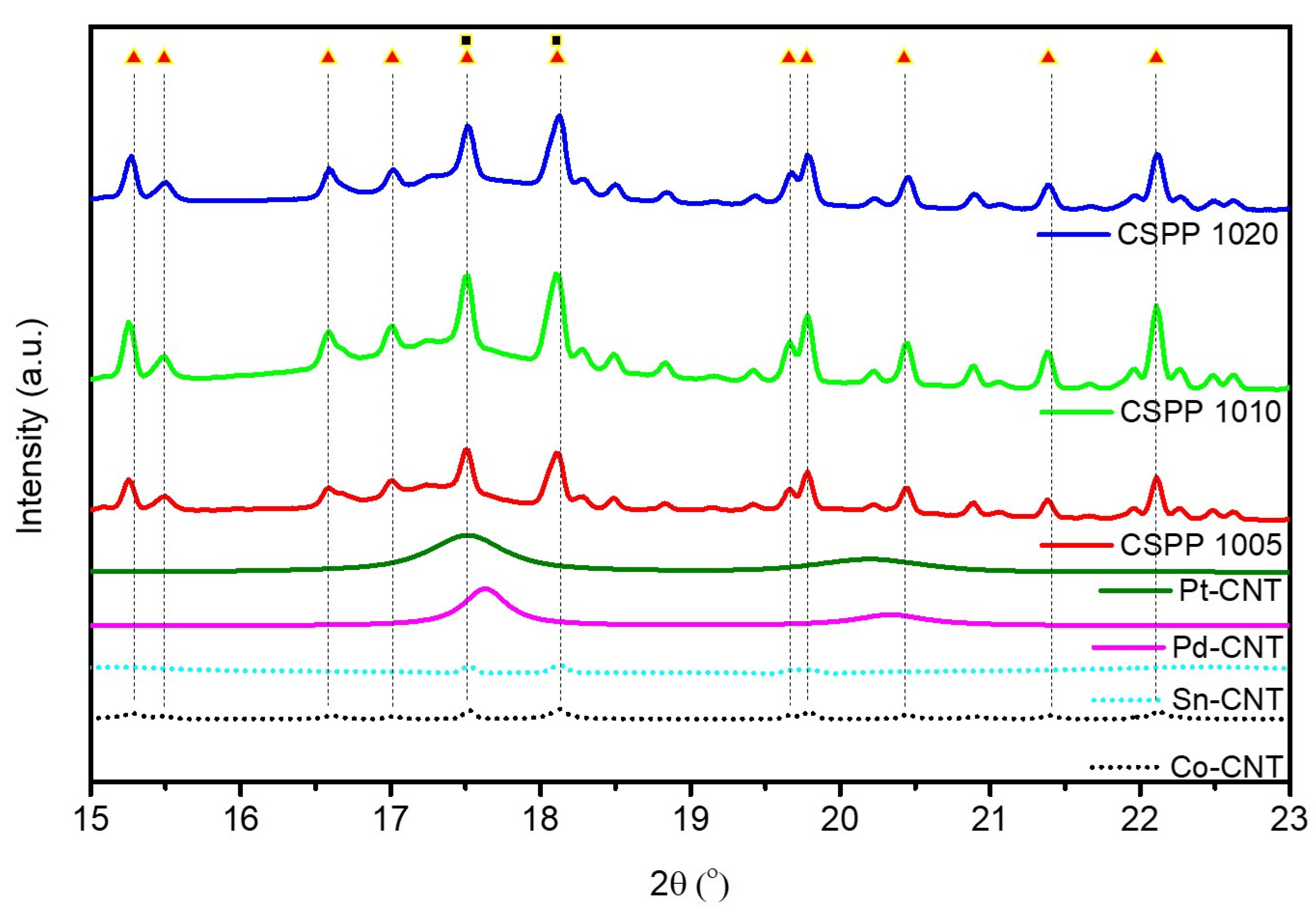
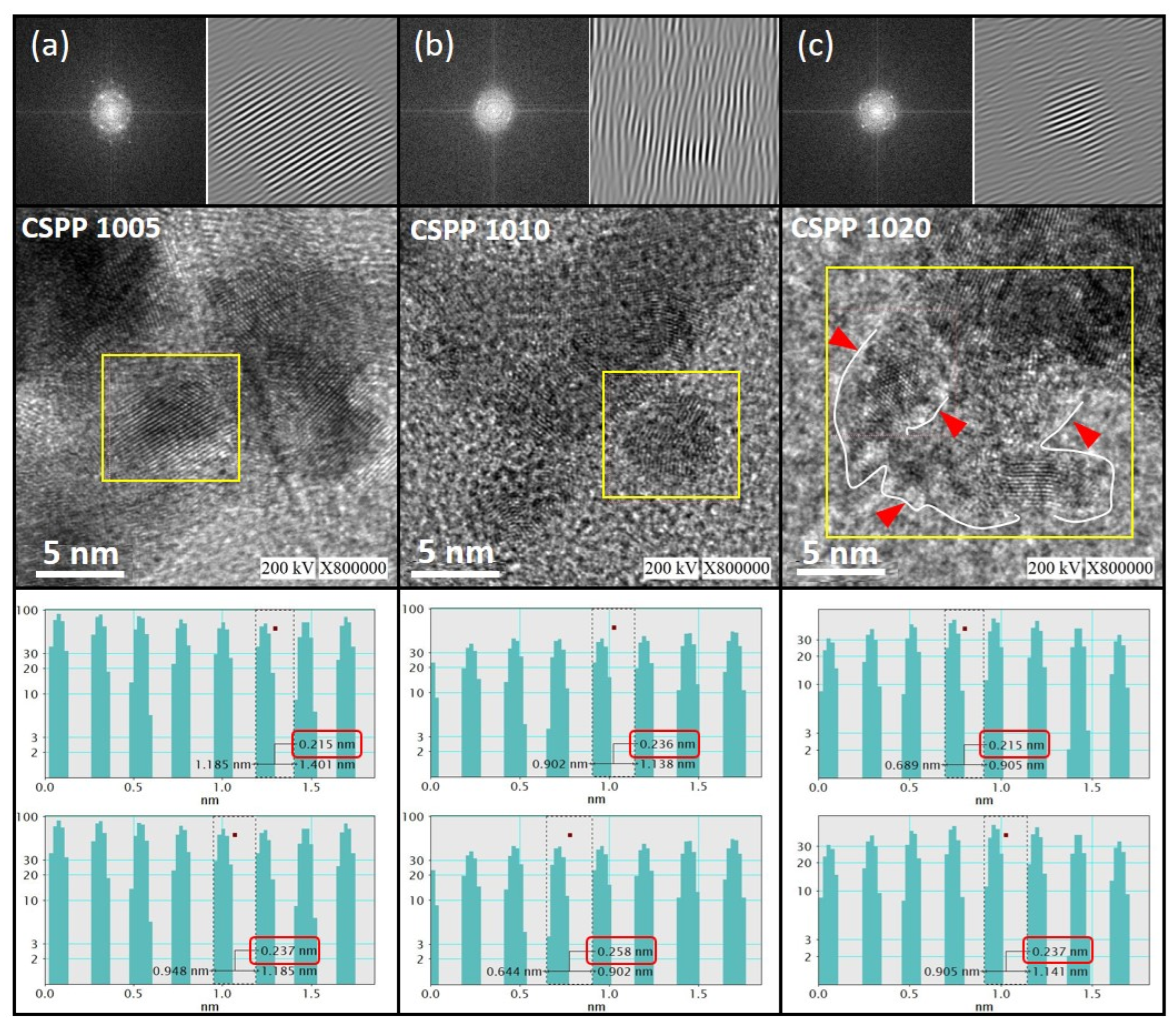
Surface Morphology and Crystal Structure

The surface morphology and crystal structure of the as-prepared CSPP NCs were disclosed by employing high-resolution transmission electron microscopy (HRTEM). The HRTEM images CSPP NCs with different Sn/Pd ratios are shown in Figure 1, whereas the corresponding Forward Fourier transformation (FFT) patterns (upper left corners) are utilized for more detailed analysis. Moreover, the Inverse Fourier Transform (IFT) images (upper right corners) and the line histograms (insets) of selected fringes are used to calculate the interplanar (d)-spacing. As shown in Figure 1, a significant variation in morphology and crystal structure is observed in CSPP NCs with variable Sn/Pd ratios and can be attributed to different extents of galvanic replacement reactions between high and low EN atoms. For a fair explanation, the HRTEM image of CoOx@SnPd (denoted as CSP; i.e., without Pt decoration) is shown in the supplementary information (Figure S1), where Pd atoms are agglomerated to form relatively larger nanoparticles with a particle size range of 20 nm (denoted by white dotted circles). In addition, a fuzzy capping layer (denoted by yellow triangles) is observed on the surface and can be assigned to the SnOx due to the relatively lower contrast. These observations integrally suggest that the SnOx-capped Pd nanoparticles are formed on the CoOx support in CSP NC. In this case, the surface-capped SnOx layer is expected to cover the Pd-reaction sites and thus, the ORR performance of CSP NC is suppressed. Furthermore, Figure 1a shows the HRTEM image of CSPP 1005 NC. Accordingly, a long-range ordered structure with clear lattice fringes confirms the presence of Pt and Pd domains on the surface of CSPP 1005 NC. Moreover, the CSPP 1005 NC exhibits a d-spacing of 0.215 nm and 0.237 nm, respectively, in the sub-surface and surface regions and can be attributed to the formation of SnPd and PdPt alloys on the sub-surface and surface region, respectively. In addition, the smooth surface of CSPP-1005 NC suggests that decorated Pt clusters are accommodated mostly in the defect regions of the SnPd composite shell. On the other hand, the CSPP 1010 NC (Figure 1b) exhibits a disordered structure (consistently proved with distorted lattice fringes in the IFT pattern (shown in the upper right corner)) with significantly increased d-spacing. These observations together confirm the exposure of SnOx on the surface of CSPP 1010 NC due to higher Sn loading (i.e., Sn/Pd ratio: 1.0). Further raising the Sn/Pd ratio to 2.0 leads to the increasing index of the galvanic replacement reaction between Pt4+ ←→ Sn0, therefore, exposure of SnOx to the surface and diffusion of Pt to the subsurface region is obvious. These scenarios are consistently shown in Figure 1c, where a thin layer of SnOx (denoted by white lines and red arrows) is formed on the surface of CSPP 1020 NC. Furthermore, the X-ray diffraction (XRD) analysis was employed for a more detailed crystal structure analysis (Figure 2 and Figure S2 in supplementary information), where the highest suppressed peaks corresponding to the Sn phase confirm that Sn domains are less exposed on the surface of CSPP 1005 NC. The exact atomic compositions of CSPP NCs have been determined by the Inductively coupled plasma-atomic emission spectrometer (ICP-AES) and are shown in Table S1.
X-ray absorption spectroscopy (XAS) at Pt L3-edge and Pd K-edge is employed to get more insights into the local atomic and electronic structure of CSPP NCs with varying Sn/Pd ratios. Figure 3a depicts the normalized X-ray absorption near edge spectra (XANES) of CSPP NCs and Pt-CNT at Pt L3-edge. The absorption edge (A) in the Pt L3-edge XANES spectra of CSPP NC reflects the electronic transition from 2p to 5d orbital, whereas the absorption edge intensity (HA) corresponds to the occupied/unoccupied density of Pt 5d orbital (i.e., the extent of electron transfer from neighbouring atoms to Pt-atoms) and the amount of surface chemisorption of oxygen species [27]. It is consistently reported in the literature that a higher density of occupied Pt d-orbitals is favourable for the ORR performance of electrocatalysts [24]. As shown in Figure 3a, the HA follows the trend CSPP 1020 > CSPP 1010 > CSPP 1005. Accordingly, the CSPP 1005 NC exhibits the lowest HA, suggesting the highest occupied density of the Pt d-orbital and can be attributed to the electron localization around the Pt clusters; therefore, the CSPP 1005 NC exhibits the highest ORR activity. Moreover, the identical position of inflection points for CSPP NCs to Pt-CNT confirms their similar metallic characteristics in all the samples. Furthermore, in the coordination environment around target atoms (Pt in this case), the extended X-ray absorption fine structure (EXAFS) analysis was used. Figure 3b shows the Fourier-transformed (FT)-EXAFS spectra of CSPP NCs with different Sn/Pd ratios and Pt-CNT at Pt L3-edge, whereas the corresponding structural parameters are listed in Table 1. Accordingly, CSPP 1005 NC shows the coordination numbers (CN)s of 3.86 and 0.842, respectively, for the Pt-Pt and Pt-Pd bond pairs, suggesting the formation of atomic-scale Pt-clusters with some extent of Pt-Pd heteroatomic intermixing (i.e., PtPd alloy formation). In addition, the CSPP 1005 NC exhibits the smallest CN for the Pt-Sn bond pair (CNPt-Sn = 0.955) among all samples, which can be attributed to the lowest extent of galvanic replacement reaction between Pt4+ ←→ Sn0 and can be attributed to the lowest Sn loading in CSPP 1005 sample. Further increasing the Sn/Pd ratio to 1.0 leads to the higher kinetics of galvanic replacement reaction between Pt4+ ←→ Sn0 and thus, the CN for the Pt-Sn bond pair (CNPt-Sn = 1.178) is increased. On the other hand, the CN for the Pt-Pd bond pair (CNPt-Pd = 0.286) in CSPP 1010 NC is decreased as compared to that of CSPP 1005 NC (CNPt-Pd = 0.842). These scenarios confirm that with increasing Sn metal loading, the Sn atoms tend to deposit on the surface of CSPP 1010 NC and thus, interaction between Pt and Pd domains is reduced. Such characteristics are further confirmed by the increased CN for the Pt-Pt bond pair in CSPP 1010 NC (CNPt-Pd = 4.351) as compared to that of CSPP 1005 NC (CNPt-Pt = 3.86). It is well-known fact that the metal nanoclusters tend to be better dispersed on a metal support instead of metal-oxide support. Herein, with the similar Pt loading, the lower CN for Pt-Pt bond pair in CSPP 1005 NC as compared to CSPP 1010 NC confirms their better dispersion. Accordingly, the CSPP 1005 NC comprises more Pd atoms on the surface, while CSPP 1010 NC contains SnOx on the surface. Additionally, the decreased CN for Pt-Pt, Pt-Pd and Pt-Sn bond pairs in CSPP 1020 NC, along with the existence of the Pt-O bond pair, implies the formation of Pt-clusters in the SnOx layer in the sub-surface region.
Results of Pd K-edge XANES analysis (Figure 3c) further reveal the afore-mentioned scenarios. In a Pd K-edge XANES spectra, the two absorption edges M and N, respectively, correspond to the oxide and metallic characteristics of Pd atoms [28]. Accordingly, with the intense peak N and the identical inflection point position of CSPP NC as that of Pd-CNT confirms the metallic characteristics of Pd atoms in all the samples. Moreover, the highest intensity of absorption edge N indicates the severe charge relocation from Pd to Pt in CSPP 1005 NC, which is consistent with former Pt L3-edge observations. Furthermore, Figure 3d show the EXAFS spectra of CSPP NCs and Pd-CNT at Pd K-edge, while the corresponding structural parameters are summarized in Table 1. Accordingly, the higher CNs for Pd-Pd and Pd-Sn bond pairs as compared to that of the Pd-Pt and Pd-Sn bond pairs confirms the formation of SnPd composite in all the NCs. In addition, with the absence of Pt-Co bond pairs, the existence of Pd-Co bond pairs in all the samples confirms the formation of CoOx@SnPd core-shell NCs with the surface decoration of Pt-clusters.
Further insights into the variations of the surface chemical environment of the CSPP NCs with different Sn/Pd ratios were obtained by cyclic voltammetry (CV) analysis. Figure 4 shows the CV curves of the CSPP NCs and the commercial J.M.-Pt/C catalyst. All the CV curves were measured in an N2-saturated 0.1 M KOH electrolyte solution at a scan rate of 20 mV/s. As shown in Figure 4, all the superimposed CV curves demonstrate three characteristic features (region), including: (i) the underpotential deposition region of hydrogen (UPD_H, highlighted in yellow) due to adsorption (reverse sweep)/desorption (forward sweep) of hydrogen (E < 0.40 V vs. RHE) followed by (ii) a double-layer region in between of 0.4 < E < 0.55 V vs. RHE and (iii) the oxide formation (in the forward sweep)/reduction (reverse sweep) region above 0.550 V vs. RHE. Accordingly, the existence of a pair of two peaks (EHdes-i and EHads-i) and (EHdes-ii and EHads-ii) corresponds to the hydrogen desorption (EHdes-i and EHdes-ii) and adsorption (EHads-i and EHads-ii) on the different facets of Pt-crystal, confirming the Pt nanoparticles in the commercial J.M.-Pt/C catalyst. For CSPP NCs, the CSPP 1005 NC exhibits relatively suppressed but similar peak profiles (denoted by red arrows) to that of the commercial J.M.-Pt/C catalyst in the UPD_H region. Previously published literature reported that such peaks in the UPD_H region refer to the strong hydrogen evolution activity by the surface atomic species [29]. These scenarios confirm the presence of Pt-clusters on the surface of CSPP 1005 NC. Besides, the CSPP 1010 and CSPP 1020 NCs show smeared peak profiles in the UPD_H region and can be attributed to the presence of more SnOx domains on the surface. In addition, the oxide reduction peak (i.e., EOdes) position in the reverse sweep refers to the energy barrier for the reduction of the oxide phase from the material’s surface and is directly related to the ORR Performance of NCs [30]. Accordingly, the oxide reduction peak (EOdes) for CSPP 1005 NC is shifted to the highest potential among all the NCs, implying the lowest energy for ORR facilitations and thus the highest ORR performance as compared to CSPP 1010 and CSPP 1020 NCs [29]. Herein, it is worth noticing that the onset potential of the commercial J.M.-Pt/C sample is lower when compared to CSPP-1005 NC, which is in good agreement with the linear sweep voltammetry (LSV) polarization curves (Figure 5a). These scenarios suggest that the high mass activity of CSPP 1005 NC should arise due to the high current in mixed kinetically and diffusion-controlled regions.
By cross-referencing the results of the above-discussed HRTEM, XAS and electrochemical inspections (CV), the atomic configurations of CSPP NCs with different Sn/Pd ratios are proposed and shown in Scheme 1. First, the long-range ordered atomic structure with clear lattice fringes in the HRTEM inspection along with the highest CN for Pt-Pd bond pair and the existence of sharp peaks in the underpotential deposition region of hydrogen confirms the presence of atomic Pt clusters and PtPd alloys on the surface of CSPP 1005 NC. Further raising the Sn/Pd ratios from 0.5 to 1.0 (i.e., CSPP 1010) leads to more exposure of SnOx domains to the surface and is consistently proven by the increased CN for the Pt-Sn bond pair and decreased CN for the Pt-Pd bond pair in CSPP 1010 NC. These scenarios are cross-referenced by the disordered atomic arrangements in the HRTEM image and smeared peak profile in the underpotential deposition region of hydrogen in CV curves. For CSPP 1020 NC, the surface SnOx layer capped polycrystalline structure can be observed in the HRTEM image. Moreover, the existence of CN for Pt-O bond pair confirms the formation of Pt clusters in the sub-surface region.
Inspired by the potential traits, the ORR performance of CSPP NCs with variable Sn/Pd ratios is determined by the linear sweep voltammetry (LSV) polarization in 0.1 M KOH electrolyte with continuously purging the oxygen. Figure 5a represents the LSV polarization curves of CSPP 1005, CSPP 1010, CSPP 1020 and the commercial J.M.-Pt/C catalyst, where the CSPP 1005 NC exhibits the highest half-wave potential (E1/2) (0.865 V) and onset potential (EOC) (0.922 V) among the NCs under investigation (Figure 5b), which is consistent with the oxide reduction peak position in CV curves. The E1/2 and EOC refer to the energy barrier for initiating the ORR on the surface of the NC and are directly correlated to the ORR performance of the NCs [31]. Consequently, the highest E1/2 and EOC indicate the lowest energy barrier for initiating the ORR on the surface of CSPP 1005 NC. Moreover, the LSV curves determined kinetic current densities (Jk) of the CSPP NCs are shown in Figure 5c and further normalized with respect to the Pt metal loading for obtaining the mass activities (MA)s. Consistent with the E1/2 and EOC, the CSPP 1005 NC shows the highest MA (3034.7 mA mgPt−1) among all NCs (Figure 5d). Additionally, as shown in Figure 5e, the Koutecky-Levich (K.L.) plots indicate that CSPP NCs follow the four-electron transfer pathway during ORR. Moreover, the CSPP 1005 NC exhibits the lowest Tafel slope (Figure 5f), suggesting the highest reaction kinetics. For clarifying the effects of decorated Pt clusters, the electrochemical results of Co@SnPd NC (i.e., without Pt decoration) have been shown in Figure S3 in the supplementary information.

3. Experimental Section

3.1. Materials and Methods

Pt-clusters decorated CoOx@SnPd core-shell nanocatalysts were prepared via a sequential, robust wet-chemical reduction method. The proposed sequential wet-chemical reduction method provides proper control of various parameters (impregnation temperature, impregnation time, and reagent inlet sequence) during crystal growth, which allows the preparation of material with the desired size, shape and morphology. In addition, this one-pot method is user-friendly, and owing to its easiness and mild requirements (magnetic stirring), it can easily be adopted in the industry. Before the synthesis of the nanocatalysts, the catalysts’ support (i.e., the carbon nanotube (CNT), Cnano Technology Ltd., Zhenjiang, China) was surface-functionalized via a previously reported protocol [32]. Subsequently, in the first step, 1200 mg of 5 wt.% CNT solution (in D.I. water; i.e., the actual amount of CNT support in 60 mg) was added into 1.28 g of 0.1 M CoCl3 (CoCl3·3H2O, 99%, Sigma-Aldrich Co., St. Louis, MO, USA) aqueous solution and stirred at 200 rpm for 6 h (solution A). In this step, the weight ratio of Co to CNT is 30 wt.%. After stirring, 0.0579 mg of NaBH4 (99%, Sigma-Aldrich Co.) was mixed with 5 mL D.I. water and instantly added to solution A (i.e., Co3+ads on CNT surface) to reduce the Co3+ ions and formation of Co@CNT (solution B). Then, after mixtures of Sn and Pd precursors were prepared in different ratios (Sn/Pd = 0.5, 1.0 and 2.0) and added to solution B for the formation of the SnPd composite shell over the CoOx core crystal underneath (i.e., formation of CoX@SnPd; denoted as CSP). In this step, the Sn and Pd precursors were reduced by the excessive amount of NaBH4 added in the previous step. Finally, the Pt precursor was added and reduced within 10 s to decorate the Pt clusters on the surface of the CSP NC. Prepared samples were cleaned with acetone, centrifuged, and dried at 120 °C overnight. Based on the Sn/Pd ratios, the as-prepared samples are referred to as CSPP 1005 (Pd/Sn = 1:0.5), CSPP 1010 (Pd/Sn = 1:1), and CSPP 1020 (Pd/Sn = 1:2), respectively.

3.2. Physical Characterization

The physical properties of the prepared samples were disclosed by the test results obtained from various electron microscopy and X-ray spectroscopy analyses. High-resolution transmission electron microscopy (HRTEM) characterizations were performed at the electron microscopy center of National Sun Yat-Sen University, Taiwan. For the preparation of the HRTEM samples, 200 mesh Cu mesh was used. In order to remove the contaminants on the surface of the samples, plasma treatment was conducted each time before loading the sample into the experimental chamber. The XRD results were obtained at the beamline of BL-01C2 in the National Synchrotron Radiation Research Center (NSRRC), Taiwan. The wavelength of incident X-rays during the experiment was 0.688 Å (18 keV). X-ray absorption spectroscopy (XAS) was carried out at beamlines BL-17C, 01C1, and BL-24A1 in NSRRC, Taiwan. To get high-quality usable data, each test was repeated at least twice and averaged for comparison. The raw data acquired directly from the XAS experiment was then processed and analyzed by using the software Athena and Artemis. For the extended X-ray absorption fine structure (EXAFS) analysis, the background was subtracted and normalized based on the edge jump obtained from the spectra. The normalized spectra were furthermore transformed from energy to k-space and then Fourier transformed to R-space to differentiate the contributions from different coordination shells. The FEFF8.0 code was used for the theoretical estimation of the backscattered amplitude and phase shift for specific atom pairs. The exact atomic compositions of the samples were acquired via ICP-AES (Jarrell-Ash, ICAP 9000, Waltham, MA, USA).

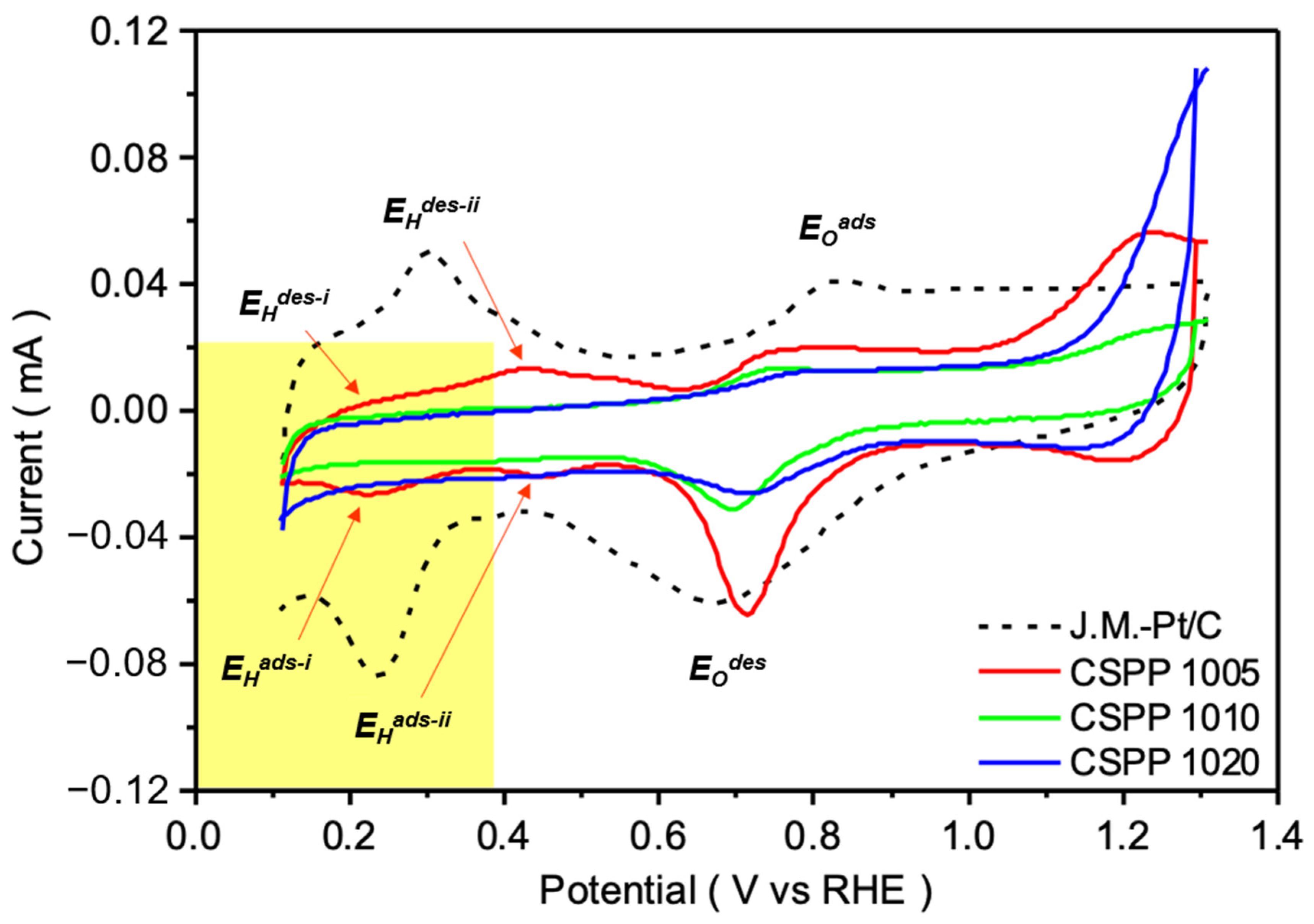
3.3. Electrochemical Analysis

Prior to the ORR test, the catalyst ink was made by dispersing 5 mg of as-prepared catalyst powder in a solution containing 1 mL of isopropanol and 50 μL of Nafion-117 (99%, Sigma-Aldrich Co.) and leaving it for ultra-sonication for 30 min (so the total volume of solution is 1050 μL). For conducting the ORR test, 10.0 μL of catalyst slurry was drop-cast and air-dried on a glassy carbon rotating disk electrode (RDE) (0.196 cm2 area) as a working electrode. All of the electrochemical experiments were conducted in a three-electrode system using a potentiostat (CHI Instruments Model 600B, Austin, TX, USA) to apply potentials and record current responses. The experiments were tested in the 0.1 M KOH (pH = 13) electrolyte. A rotation rate of 1600 rpm for the RDE was applied for linear sweep voltammetry (LSV). Nitrogen and oxygen were purged for cyclic voltammetry (CV) and LSV, respectively. A Hg/HgCl2 electrode and a platinum wire were used as the reference electrode and counter electrode, respectively.

3.4. Calculation for the ORR Activity Analysis

In this work, the ORR activity was evaluated according to their kinetic current density (JK) and mass activity (MA). The values were calculated by using the electrochemical results. JK was determined based on the Koutecký–Levich equation (shown in Equation (1)):
1 J = 1 J K + 1 J L = 1 J K + 1 B ω 0.5
where J is the measured current, JL is the mass transfer limited current density, ω is the angular velocity, and the coefficient B is as follows (shown in Equation (2)):
B = 0.62 n F C O 2 D O 2 2 3 ν 1 6
where n is the transferred electron number, F is the Faraday constant, C O 2 is the bulk concentration of O2, D O 2 is the diffusion coefficient, and ν is the kinematic viscosity of the electrolyte.
MA was determined via the calculation of JK and the catalyst loading on the glassy carbon electrode. The equation is shown below:
mass   activity   mA   mg 1 = J k × area mass   of   catalyst
where Jk is the kinetic current density (mA/cm2) and the area is the geometric area of the working electrode (0.196 cm2).

4. Conclusions

In this work, Pt-clusters decorated CoOx@SnPd core-shell (denoted as CSPP) NCs with different Sn/Pd ratios were prepared using the robust wet-chemical reduction method. Different physical characterizations and electrochemical tests were conducted to reveal the physical and chemical properties of the as-prepared samples. The results show that the modulation of the SnPd shell layer can greatly change the activity of CSPP core-shell NCs for ORR. For the optimum case, the CSPP NC with an Sn/Pd ratio of 0.5 (denoted as CSPP 1005) exhibits an outstanding MA of 3034.7 mA mgPt−1 at 0.85 V vs. RHE in 0.1 M KOH electrolyte, which significantly outnumbered the commercial J.M.-Pt/C catalyst. To sum up, a rational design of core-shell nanocatalysts to promote the ORR activity while reducing the preparation cost is demonstrated. This study verifies the possibility of preparing highly active and practical ORR catalysts that meet the industrial requirements, which is good guidance for the future development of fuel cells.

Supplementary Materials

The following supporting information can be downloaded at: https://www.mdpi.com/article/10.3390/catal12111411/s1, Figure S1: The HRTEM image of CSP nanocatalyst; Figure S2: X-ray diffraction patterns of control samples. All the spectra were measured under the incident X-rays of 18 keV; Figure S3: Electrochemical results of CSPP NCs. (a) LSV, (b) Onset potential (Voc)/half wave potential (E1/2), (c) kinetic current density and (d) ORR mass activity of CSPP NCs compared with reference sample (CSP); Table S1: The ICP-AES determined atomic composition of CSPP NCs; Table S2: Benchmark of catalysts in ORR application [29,32,33,34,35,36,37,38,39,40,41].

Author Contributions

Data curation, W.Y., A.B., C.Y. and P.-C.C.; Formal analysis, C.Y.; Funding acquisition, T.-Y.C.; Investigation, X.T.; Methodology, D.B. and T.-Y.C.; Project administration, T.-Y.C.; Resources, K.-W.W., P.-C.C. and T.-Y.C.; Supervision, T.-Y.C.; Writing—original draft, M.C.; Writing—review and editing, D.B. All authors have read and agreed to the published version of the manuscript.

Funding

This research was funded by the Ministry of Science and Technology, Taiwan (MOST 109-2923-E-007-005-, MOST 109-3116-F-007-001- and MOST 109-2112-M-007-030 -MY3).

Data Availability Statement

The data presented in this study are available on request from the corresponding author.

Acknowledgments

The authors express their gratitude to the staff of the National Synchrotron Radiation Research Center (NSRRC), in Hsinchu, Taiwan for the help in various synchrotron-based measurements.

Conflicts of Interest

The authors declare no conflict of interest.

References

  1. Jung, N.; Chung, D.Y.; Ryu, J.; Yoo, S.J.; Sung, Y.-E. Pt-based nanoarchitecture and catalyst design for fuel cell applications. Nano Today 2014, 9, 433–456. [Google Scholar] [CrossRef]
  2. Borup, R.L.; Kusoglu, A.; Neyerlin, K.C.; Mukundan, R.; Ahluwalia, R.K.; Cullen, D.A.; More, K.L.; Weber, A.Z.; Myers, D.J. Recent developments in catalyst-related PEM fuel cell durability. Curr. Opin. Electrochem. 2020, 21, 192–200. [Google Scholar] [CrossRef]
  3. Bhalothia, D.; Krishnia, L.; Yang, S.-S.; Yan, C.; Hsiung, W.-H.; Wang, K.-W.; Chen, T.-Y. Recent Advancements and Future Prospects of Noble Metal-Based Heterogeneous Nanocatalysts for Oxygen Reduction and Hydrogen Evolution Reactions. Appl. Sci. 2020, 10, 7708. [Google Scholar] [CrossRef]
  4. Sui, S.; Wang, X.; Zhou, X.; Su, Y.; Riffat, S.; Liu, C.-j. A comprehensive review of Pt electrocatalysts for the oxygen reduction reaction: Nanostructure, activity, mechanism and carbon support in PEM fuel cells. J. Mater. Chem. A 2017, 5, 1808–1825. [Google Scholar] [CrossRef]
  5. Ortiz-Herrera, J.C.; Cruz-Martínez, H.; Solorza-Feria, O.; Medina, D.I. Recent progress in carbon nanotubes support materials for Pt-based cathode catalysts in PEM fuel cells. Int. J. Hydrog. Energy 2022, 47, 30213–30224. [Google Scholar] [CrossRef]
  6. Zhao, X.; Sasaki, K. Advanced Pt-Based Core-shell Electrocatalysts for Fuel Cell Cathodes. Acc. Chem. Res. 2022, 55, 1226–1236. [Google Scholar] [CrossRef] [PubMed]
  7. Liu, M.; Zhao, Z.; Duan, X.; Huang, Y. Nanoscale Structure Design for High-Performance Pt-Based ORR Catalysts. Adv. Mater. 2019, 31, 1802234. [Google Scholar] [CrossRef]
  8. Wang, Y.; Wang, D.; Li, Y. A fundamental comprehension and recent progress in advanced Pt-based ORR nanocatalysts. SmartMat 2021, 2, 56–75. [Google Scholar] [CrossRef]
  9. Cruz-Martínez, H.; Rojas-Chávez, H.; Matadamas-Ortiz, P.T.; Ortiz-Herrera, J.C.; López-Chávez, E.; Solorza-Feria, O.; Medina, D.I. Current progress of Pt-based ORR electrocatalysts for PEMFCs: An integrated view combining theory and experiment. Mater. Today Phys. 2021, 19, 100406. [Google Scholar] [CrossRef]
  10. Qin, J.; Zhang, Y.; Leng, D.; Yin, F. The enhanced activity of Pt-Ce nanoalloy for oxygen electroreduction. Sci. Rep. 2020, 10, 14837. [Google Scholar] [CrossRef]
  11. Wang, Y.-J.; Zhao, N.; Fang, B.; Li, H.; Bi, X.T.; Wang, H. Carbon-Supported Pt-Based Alloy Electrocatalysts for the Oxygen Reduction Reaction in Polymer Electrolyte Membrane Fuel Cells: Particle Size, Shape, and Composition Manipulation and Their Impact to Activity. Chem. Rev. 2015, 115, 3433–3467. [Google Scholar] [CrossRef] [Green Version]
  12. Pan, L.; Ott, S.; Dionigi, F.; Strasser, P. Current challenges related to the deployment of shape-controlled Pt alloy oxygen reduction reaction nanocatalysts into low Pt-loaded cathode layers of proton exchange membrane fuel cells. Curr. Opin. Electrochem. 2019, 18, 61–71. [Google Scholar] [CrossRef]
  13. Kim, J.; Hong, Y.; Lee, K.; Kim, J.Y. Highly Stable Pt-Based Ternary Systems for Oxygen Reduction Reaction in Acidic Electrolytes. Adv. Energy Mater. 2020, 10, 2002049. [Google Scholar] [CrossRef]
  14. Li, H.; Dai, S.; Bhalothia, D.; Chou, J.-P.; Hu, A.; Chen, T.-Y. Collaboration between a Pt-dimer and neighboring Co-Pd atoms triggers efficient pathways for oxygen reduction reaction. Phys. Chem. Chem. Phys. 2021, 23, 1822–1834. [Google Scholar] [CrossRef] [PubMed]
  15. Weber, P.; Weber, D.J.; Dosche, C.; Oezaslan, M. Highly Durable Pt-Based Core-Shell Catalysts with Metallic and Oxidized Co Species for Boosting the Oxygen Reduction Reaction. ACS Catal. 2022, 12, 6394–6408. [Google Scholar] [CrossRef]
  16. Strasser, P.; Kühl, S. Dealloyed Pt-based core-shell oxygen reduction electrocatalysts. Nano Energy 2016, 29, 166–177. [Google Scholar] [CrossRef] [Green Version]
  17. Maiti, S.; Maiti, K.; Curnan, M.T.; Kim, K.; Noh, K.-J.; Han, J.W. Engineering electrocatalyst nanosurfaces to enrich the activity by inducing lattice strain. Energy Environ. Sci. 2021, 14, 3717–3756. [Google Scholar] [CrossRef]
  18. Deng, Y.-J.; Tripkovic, V.; Rossmeisl, J.; Arenz, M. Oxygen Reduction Reaction on Pt Overlayers Deposited onto a Gold Film: Ligand, Strain, and Ensemble Effect. ACS Catal. 2016, 6, 671–676. [Google Scholar] [CrossRef] [Green Version]
  19. Bhalothia, D.; Chen, P.-C.; Yan, C.; Wang, K.-W.; Chen, T.-Y. Heterogeneous NiO2-to-Pd Epitaxial Structure Performs Outstanding Oxygen Reduction Reaction Activity. J. Phys. Chem. C 2020, 124, 2295–2306. [Google Scholar] [CrossRef]
  20. Bhalothia, D.; Wang, S.-P.; Lin, S.; Yan, C.; Wang, K.-W.; Chen, P.-C. Atomic Pt-Clusters Decoration Triggers a High-Rate Performance on Ni@Pd Bimetallic Nanocatalyst for Hydrogen Evolution Reaction in Both Alkaline and Acidic Medium. Appl. Sci. 2020, 10, 5155. [Google Scholar] [CrossRef]
  21. Beniwal, A.; Bhalothia, D.; Yeh, W.; Cheng, M.; Yan, C.; Chen, P.-C.; Wang, K.-W.; Chen, T.-Y. Co-Existence of Atomic Pt and CoPt Nanoclusters on Co/SnOx Mix-Oxide Demonstrates an Ultra-High-Performance Oxygen Reduction Reaction Activity. Nanomaterials 2022, 12, 2804. [Google Scholar] [CrossRef] [PubMed]
  22. Bhalothia, D.; Chen, P.-C.; Yan, C.; Yeh, W.; Tsai, D.-L.; Chan, T.-S.; Wang, K.-W.; Chen, T.-Y. Heterogeneous assembly of Pt-clusters on hierarchically structured CoOx@SnPd2@SnO2 quaternary nanocatalysts manifesting oxygen reduction reaction performance. New J. Chem. 2020, 44, 9712–9724. [Google Scholar] [CrossRef]
  23. Bhalothia, D.; Dai, S.; Wang, S.-P.; Yan, C.; Huang, T.-H.; Chen, P.-C.; Hiraoka, N.; Wang, K.-W.; Chen, T.-Y. Sub-nanometer Pt cluster decoration enhances the oxygen reduction reaction performances of NiOx supported Pd nano-islands. Sustain. Energy Fuels 2020, 4, 809–823. [Google Scholar] [CrossRef]
  24. Bhalothia, D.; Lin, C.-Y.; Yan, C.; Yang, Y.-T.; Chen, T.-Y. H2 Reduction Annealing Induced Phase Transition and Improvements on Redox Durability of Pt Cluster-Decorated Cu@Pd Electrocatalysts in Oxygen Reduction Reaction. ACS Omega 2019, 4, 971–982. [Google Scholar] [CrossRef] [Green Version]
  25. Bhalothia, D.; Lin, C.-Y.; Yan, C.; Yang, Y.-T.; Chen, T.-Y. Effects of Pt metal loading on the atomic restructure and oxygen reduction reaction performance of Pt-cluster decorated Cu@Pd electrocatalysts. Sustain. Energy Fuels 2019, 3, 1668–1681. [Google Scholar] [CrossRef]
  26. Bhalothia, D.; Hsiung, W.-H.; Yang, S.-S.; Yan, C.; Chen, P.-C.; Lin, T.-H.; Wu, S.-C.; Chen, P.-C.; Wang, K.-W.; Lin, M.-W.; et al. Submillisecond Laser Annealing Induced Surface and Subsurface Restructuring of Cu–Ni–Pd Trimetallic Nanocatalyst Promotes Thermal CO2 Reduction. ACS Appl. Energy Mater. 2021, 4, 14043–14058. [Google Scholar] [CrossRef]
  27. Bhalothia, D.; Chou, J.-P.; Yan, C.; Hu, A.; Yang, Y.-T.; Chen, T.-Y. Programming ORR Activity of Ni/NiOx@Pd Electrocatalysts via Controlling Depth of Surface-Decorated Atomic Pt Clusters. ACS Omega 2018, 3, 8733–8744. [Google Scholar] [CrossRef] [Green Version]
  28. Hong, S.; Hwang, H.; Hwang, J.P.; Kim, J.W.; Lee, C.H.; Lee, J. The effect of morphological difference and hydride incorporation on the activity of Pd/C catalysts in direct alkaline formate fuel cell. Catal. Today 2021, 359, 28–34. [Google Scholar] [CrossRef]
  29. Dai, S.; Chou, J.-P.; Wang, K.-W.; Hsu, Y.-Y.; Hu, A.; Pan, X.; Chen, T.-Y. Platinum-trimer decorated cobalt-palladium core-shell nanocatalyst with promising performance for oxygen reduction reaction. Nat. Commun. 2019, 10, 440. [Google Scholar] [CrossRef] [Green Version]
  30. Huang, T.-H.; Bhalothia, D.; Dai, S.; Yan, C.; Wang, K.-W.; Chen, T.-Y. Bifunctional Pt-SnOx nanorods for enhanced oxygen reduction and hydrogen evolution reactions. Sustain. Energy Fuels 2021, 5, 2960–2971. [Google Scholar] [CrossRef]
  31. Bhalothia, D.; Fan, Y.-J.; Lai, Y.-C.; Yang, Y.-T.; Yang, Y.-W.; Lee, C.-H.; Chen, T.-Y. Conformational Effects of Pt-Shells on Nanostructures and Corresponding Oxygen Reduction Reaction Activity of Au-Cluster-Decorated NiOx@Pt Nanocatalysts. Nanomaterials 2019, 9, 1003. [Google Scholar] [CrossRef] [PubMed] [Green Version]
  32. Bhalothia, D.; Tsai, D.-L.; Wang, S.-P.; Yan, C.; Chan, T.-S.; Wang, K.-W.; Chen, T.-Y.; Chen, P.-C. Ir-oxide mediated surface restructure and corresponding impacts on durability of bimetallic NiOx@Pd nanocatalysts in oxygen reduction reaction. J. Alloys Compd. 2020, 844, 156160. [Google Scholar] [CrossRef]
  33. Luo, L.-M.; Zhan, W.; Zhang, R.-H.; Chen, D.; Hu, Q.-Y.; Guo, Y.F.; Zhou, X.-W. Ternary CoAuPd and binary AuPd electrocatalysts for methanol oxidation and oxygen reduction reaction: Enhanced catalytic performance by surface reconstruction. J. Power Sources 2019, 412, 142–152. [Google Scholar] [CrossRef]
  34. Feng, Y.; Shao, Q.; Ji, Y.; Cui, X.; Li, Y.; Zhu, X.; Huang, X. Surface-modulated palladium-nickel icosahedra as high-performance non-platinum oxygen reduction electrocatalysts. Sci. Adv. 2018, 4, 7. [Google Scholar] [CrossRef] [PubMed] [Green Version]
  35. Chen, H.-Y.T.; Chou, J.-P.; Lin, C.-Y.; Hu, C.-W.; Yang, Y.-T.; Chen, T.-Y. Heterogeneous Cu-Pd binary interface boosts stability and mass activity of atomic Pt clusters in the oxygen reduction reaction. Nanoscale 2017, 9, 7207–7216. [Google Scholar] [CrossRef] [PubMed]
  36. Jiang, J.; Gao, H.; Lu, S.; Zhang, X.; Wang, C.-Y.; Wang, W.-K.; Yu, H.-Q. Ni-Pd core-shell nanoparticles with Pt-like oxygen reduction electrocatalytic performance in both acidic and alkaline electrolytes. J. Mater. Chem. A 2017, 5, 9233–9240. [Google Scholar] [CrossRef]
  37. Wu, Y.; Wang, C.; Zou, L.; Huang, Q.; Yang, H. Incorporation of cobalt into Pd2Sn intermetallic nanoparticles as durable oxygen reduction electrocatalyst. J. Electroanal. Chem. 2017, 789, 167–173. [Google Scholar] [CrossRef]
  38. Cui, Z.; Chen, H.; Zhao, M.; DiSalvo, F.J. High-Performance Pd3Pb Intermetallic Catalyst for Electrochemical Oxygen Reduction. Nano Lett. 2016, 16, 2560–2566. [Google Scholar] [CrossRef]
  39. Holade, Y.; da Silva, R.G.; Servat, K.; Napporn, T.W.; Canaff, C.; de Andrade, A.R.; Kokoh, K.B. Facile synthesis of highly active and durable PdM/C (M = Fe, Mn) nanocatalysts for the oxygen reduction reaction in an alkaline medium. J. Mater. Chem. A 2016, 4, 8337–8349. [Google Scholar] [CrossRef]
  40. Kuttiyiel, K.A.; Sasaki, K.; Su, D.; Wu, L.; Zhu, Y.; Adzic, R.R. Gold-promoted structurally ordered intermetallic palladium cobalt nanoparticles for the oxygen reduction reaction. Nat. Commun. 2014, 5, 5185. [Google Scholar] [CrossRef] [Green Version]
  41. Lu, Y.; Jiang, Y.; Gao, X.; Wang, X.; Chen, W. Strongly Coupled Pd Nanotetrahedron/Tungsten Oxide Nanosheet Hybrids with Enhanced Catalytic Activity and Stability as Oxygen Reduction Electrocatalysts. J. Am. Chem. Soc. 2014, 136, 11687–11697. [Google Scholar] [CrossRef] [PubMed]
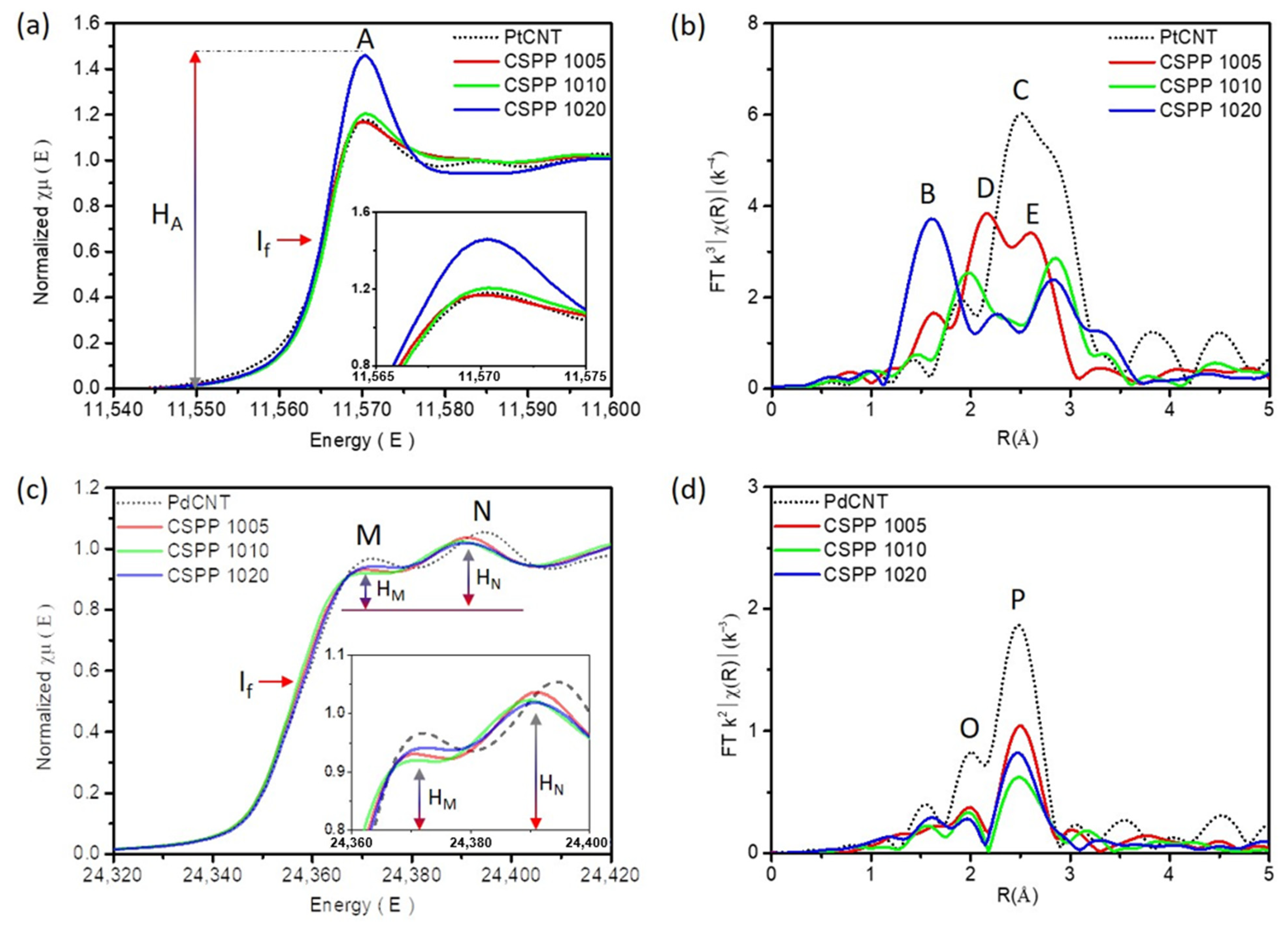
Figure 1. HRTEM images of CSPP NCs (a) CSPP 1005, (b) CSPP 1010, and (c) CSPP 1020. The d-spacing values of experimental NCs are calculated by using Inverse Fourier Transform (IFT) images (upper right corners) and their corresponding line histograms (insets). Fourier transformation (FFT) patterns of the selected area in the HRTEM images are shown in the upper left corners.
Catalysts 12 01411 g001
Figure 2. X-ray diffraction patterns of CSPP NCs and control samples. All the spectra were measured under the incident X-rays of 18 keV.
Catalysts 12 01411 g002
Figure 3. X-ray absorption spectroscopy of CSPP NCs and control samples. (a) XANES and (b) FT-EXAFS spectra of CSPP NCs at the Pt L3-edge, compared with the Pt-CNT. (c) XANES and (d) FT-EXAFS spectra of CSPP NCs at the Pd K-edge, compared with Pd-CNT.
Catalysts 12 01411 g003
Figure 4. Cyclic voltammetry (CV) plots of CSPP NCs compared with the commercial J.M.-Pt/C NC. All the CV curves were obtained in an N2-saturated 0.1 M KOH electrolyte.
Catalysts 12 01411 g004
Figure 5. Electrochemical results of CSPP NCs. (a) LSV, (b) Onset potential (Voc)/half wave potential (E1/2), (c) kinetic current density, and (d) ORR mass activity of CSPP NCs compared with the commercial J.M.-Pt/C NCs. (e) The Koutecky–Levich (K.L.) plots and (f) the Tafel slopes of CSPP NCs.
Catalysts 12 01411 g005
Scheme 1. Schematic illustration of the proposed structure of CSPP NCs.
Catalysts 12 01411 sch001
Table 1. Quantitative results of X-ray absorption spectroscopy model analysis at the Pt L3-edge and Pd K-edge of experimental NCs.
SamplePtL3-Edge
Bond PairCNR (Å)R-FactorΔE0χ
CSPP 1005Pt-Pt3.862.6720.00050.18968.23%
Pt-Pd0.8422.670 14.89%
Pt-Sn0.9552.587 16.88%
CSPP 1010Pt-Pt4.3512.7260.0242.87474.82%
Pt-Pd0.2862.689 4.92%
Pt-Sn1.1782.630 20.26%
CSPP 1020Pt-Pt3.9062.7270.0045.38557.07%
Pt-Pd0.2792.671 4.08%
Pt-Sn0.9702.633 14.17%
Pt-O1.6891.948 24.68%
SamplePd K-Edge
Bond PairCNR (Å)R-FactorΔE0χ
CSPP 1005Pd-Pd4.0502.7050.0003−1.66643.12%
Pd-Pt0.2342.746 2.49%
Pd-Sn4.5882.795 48.85%
Pd-Co0.5202.623 5.54%
CSPP 1010Pd-Pd3.5932.6990.0023−0.79050.85%
Pd-Pt0.3132.677 4.43%
Pd-Sn2.6612.795 37.66%
Pd-Co0.4992.713 7.06%
CSPP 1020Pd-Pd4.6622.6970.0011−2.73248.34%
Pd-Pt1.0152.670 10.53%
Pd-Sn3.3772.794 35.02%
Pd-Co0.5892.735 6.11%
Publisher’s Note: MDPI stays neutral with regard to jurisdictional claims in published maps and institutional affiliations.

