Article

The 3D-Printing Fabrication of Multichannel Silicone Microreactors for Catalytic Applications

Institute for Advanced Materials and Mathematics (InaMat2), Universidad Pública de Navarra (UPNA), Edificio Jerónimo de Ayanz, Campus de Arrosadia, 31006 Pamplona-Iruña, Spain
*
Authors to whom correspondence should be addressed.
Catalysts 2023, 13(1), 157; https://doi.org/10.3390/catal13010157
Submission received: 14 November 2022 / Revised: 31 December 2022 / Accepted: 7 January 2023 / Published: 9 January 2023

Abstract

:
Microstructured reactors (MSRs) are especially indicated for highly demanding heterogeneous catalysis due to the small channel dimensions that minimize diffusional limitations and enhance mass and heat transport between the fluid and the catalyst. Herein, we present the fabrication protocol of the fused filament 3D printing of silicone monolithic microreactors based on a multichannel design. Microchannels of 200 to 800 µm in width and up to 20 mm in length were developed following the scaffold-removal procedure using acrylonitrile butadiene styrene (ABS) as the material for the 3D-printed scaffold fabrication, polydimethylsiloxane (PDMS) as the building material, and acetone as the ABS removing agent. The main printing parameters such as temperature and printing velocity were optimized in order to minimize the bridging effect and filament collapsing and intercrossing. Heterogeneous catalysts were incorporated into the microchannel walls during fabrication, thus avoiding further post-processing steps. The nanoparticulated catalyst was deposited on ABS scaffolds through dip coating and transferred to the microchannel walls during the PDMS pouring step and subsequent scaffold removal. Two different designs of the silicone monolithic microreactors were tested for four catalytic applications, namely liquid-phase 2-nitrophenol photohydrogenation and methylene blue photodegradation in aqueous media, lignin depolymerization in ethanol, and gas-phase CO2 hydrogenation, in order to investigate the microreactor performance under different reaction conditions (temperature and solvent) and establish the possible range of applications.

Graphical Abstract

1. Introduction

Microstructured reactors (MSRs) have become a very important topic in research and development strategies for catalytic engineering. The inherent characteristics associated with their micrometric dimensions and their high surface-to-volume ratios, such as more efficient contact between reactants and catalysts, improved heat and mass transfer, and reduction in fabrication material consumption, have led to multiple benefits in numerous applications [1]. Microreactors having characteristic dimensions of the order of ten to several hundred micrometers greatly reduce diffusional transport limitations and show improved performances compared with conventional systems [2]. This approach to process intensification has been considered very promising in a variety of applications such as synthetic fuel production [3,4,5,6], where compact decentralized solutions are required, or in photocatalysis, where modularity is needed for optimal light distribution [7,8].
Microstructuration can be performed following different fabrication methods and techniques such as micromachining, lithography, extrusion, etc., and manufactured in a variety of materials, including metals, silicon, polymers, glass, or ceramics, resulting in a large collection of new MSR designs [9], ranging from multichannel monoliths with intricate porosity to flat interconnected microchannel reactors. Nowadays, 3D printing is facilitating easy and low-cost fabrication of structured microchannel reactors [10,11,12,13,14]. Versatility in terms of design and construction materials is currently available by selecting the appropriate additive manufacturing technique. Together with fabrication, the integration of catalysts into reactor walls is of key importance [15]. The functionalization of catalytic materials and surfaces and the preparation methods for thin films and coatings are essential for successful catalyst incorporation, homogeneity, and good adherence to the reactor walls [16]. While washcoating is the most common method for catalyst incorporation in MSRs, improving the process of adherence to the reactor wall to avoid any catalyst loss during reaction remains a challenging aspect of catalytic MSR fabrication [17].
Polydimethylsiloxane (PDMS) is one of the most frequently used materials for some microfluidic applications due to its biocompatibility, transparency, and ease of replication [18]. This silicone has been largely utilized for the development of biomedical microdevices and microreactors intended for operation under mild conditions. PDMS use in catalytic applications is limited by several factors such as its relatively low maximum operating temperature of 250 °C, although appropriate formulation and synthesis may extend this limit up to 350 °C [19]. Other drawbacks include its planar dimensions and that the conventional procedures of its use require clean room facilities, and sealing may be problematic. Notably, 3D printing as enabling technology has allowed many researchers to manufacture their own designs and prototypes without the need for large facilities or time-consuming training. Nowadays, it is possible to replace the typical photolithography-based mold with a 3D-printed mold with high accuracy using stereolithography (SLA) printers. Currently, 3D-printed sacrificial molds can be used to fabricate microchannels with complex flow paths. Saggiomo and Velders [20] proposed a sacrificial mold method to create MSRs without the necessity of sealing. Using a standard fused deposition modeling (FDM) printer, these authors fabricated ABS (acrylonitrile butadiene styrene) sacrificial molds that could be removed through dissolution in acetone, leading to the designed device in PDMS. A similar procedure can be followed using different sacrificial materials, such as polylactic acid (PLA) or polyglycolic acid (PGA), and removal agents to fabricate highly porous foams or intricate microchannels [21,22,23,24].
Herein, following the sacrificial mold method, we fabricated silicone monolithic microreactors with parallel microchannels similar to the well-known monoliths made of metal (stainless steel) or ceramics (cordierite). Scaffolds with a multirod design were 3D-printed in ABS, coated with four different nanoparticulated catalysts, and embedded in PDMS. During PDMS curing, the catalyst was transferred from the ABS scaffold to PDMS, and, by removing ABS with acetone, the final silicone multichannel monolith with the catalyst was integrated into the channel walls without the need for any post-treatment. Several microreactors were tested in a variety of applications to demonstrate their feasibility under different reaction conditions (temperature, irradiation, and solvents): photodegradation of methylene blue, photohydrogenation of 2-nitrophenol, lignin depolymerization, and CO2 methanation.

2. Results and Discussion

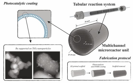
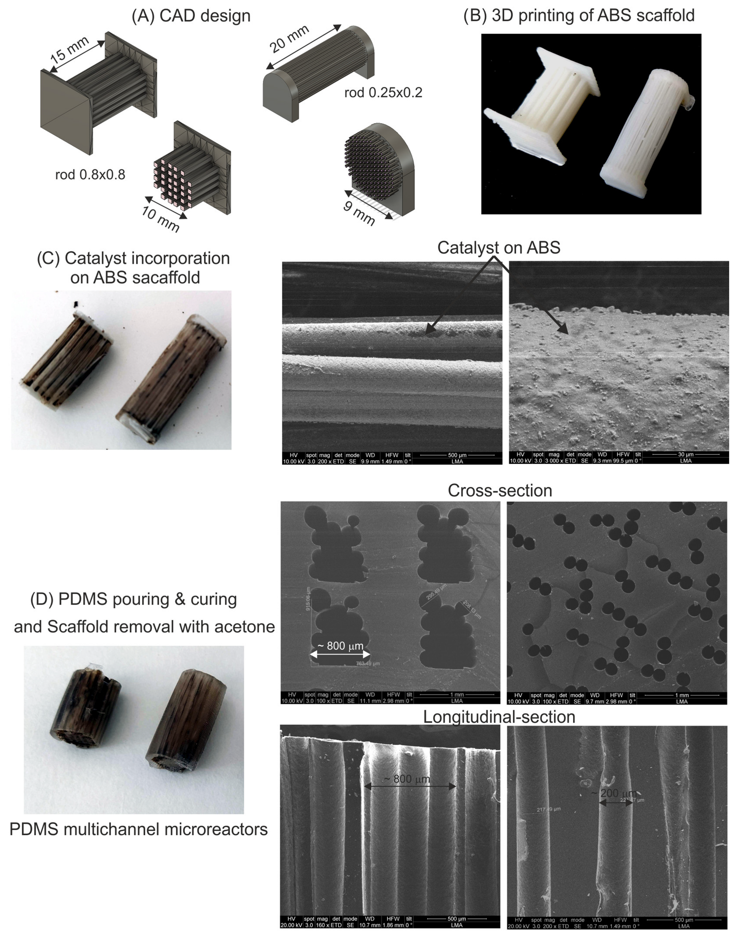
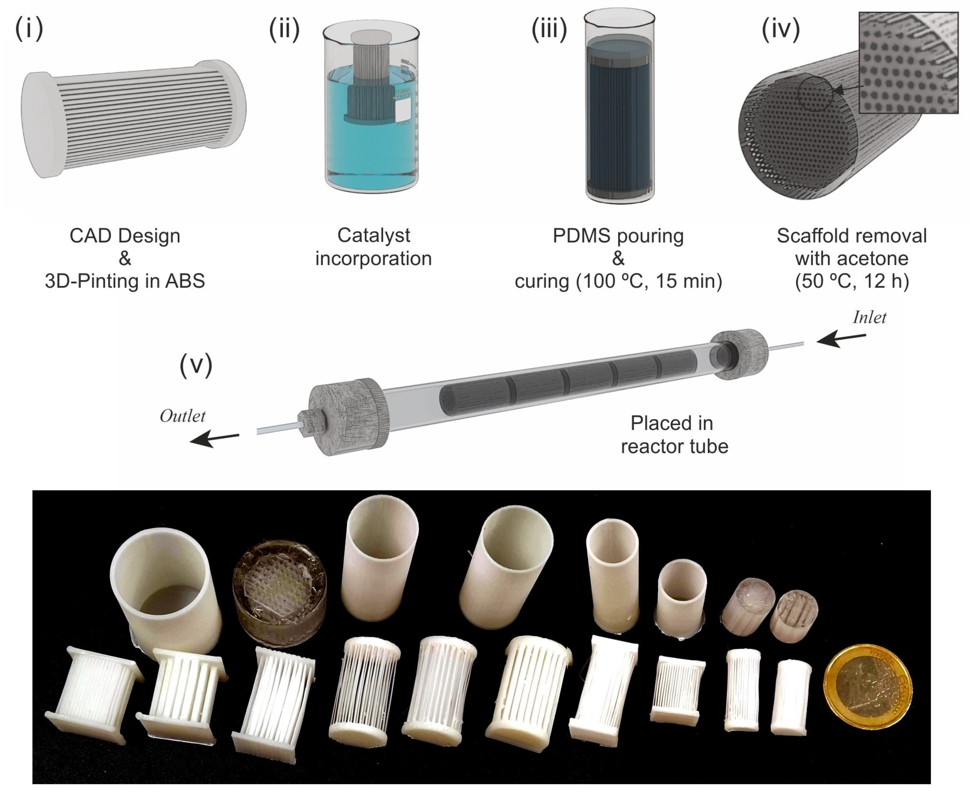
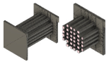
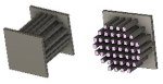
2.1. Multichannel Microreactor Fabrication

Multichannel scaffolds were designed as negative images of parallel rods with square sections and were printed in ABS with 0.25–1 mm in width and 10–20 mm in length. The scaffolds were assembled in a multirod configuration with different sizes according to the Ultimaker Cura laminator settings, and the nozzle was selected to optimize the finishing of the pieces according to the design dimensions. The extrusion parameters, mainly the printing temperature and velocity, are crucial to avoid bridging problems and rod collapsing, as well as to obtain uniformly shaped channels [24]. After preliminary tests, six designs were selected for further monolithic microreactor development. The main characteristics of the selected designs and the optimized printing parameters used for the fabrication of the ABS scaffolds are gathered in Table 1.
The two designs shown in Figure 1A,B were selected to be tested for the catalytic applications in order to determine their behavior under different reaction conditions (temperatures, light radiation, or solvents). One of the main advantages of this technique is the easy tuning of the resulting MSRs. Thus, the overall diameter of the mold can be adjusted to be held in reactor tubes of different diameters. Similarly, the number of rods of the device (density %) can be modified depending on the space–time (the relationship between the catalyst mass and the feed flow rate) required for each application. Nevertheless, achieving a good resolution and structural stability of the microreactor requires using a relatively low density of channels (<30%) defined as the fluidic volume divided by the reactor volume. The printing parameters were optimized to minimize bridging problems and avoid rod collapse during printing. For thinner rods, a 0.25 mm nozzle was selected, whereas a nozzle size of 0.4 mm was utilized for the rest. Nozzles as wide as 0.8 mm were discarded due to the poor resolution caused by ABS agglomeration and rod collapse.
Selected heterogeneous catalysts were incorporated into the ABS rods via dip coating. Previously, the wettability of the ABS surface was improved using an atmospheric plasma treatment through corona discharge, creating surface hydroxyl groups that promote the adhesion of the catalyst to ABS. Better adherence to the outer surface of the ABS rods was observed (see SEM images in Figure 1C) for all the catalytic nanoparticles considered in this study. The nanoparticles were also more effectively incorporated into the thicker rods, where the distance between rods was higher, and wettability was improved. This is attributed to the fact that the atmospheric plasma treatment applied did not allow the generated oxygen radicals to access the surface of the inner rods. As a result, a completely homogeneous catalyst layer could not be obtained all over the rod surface. Therefore, it would be desirable to explore the use of another surface functionalization system such as a vacuum plasma oven instead of atmospheric plasma.
After catalyst incorporation, the coated ABS molds were placed inside 3D-printed tubes of the same diameter as the selected reaction tube. Then, liquid PDMS was poured until the mold was fully submerged, and vigorous degasification was applied before the curing step to prevent the formation of defects due to the presence of bubbles. The resulting PDMS–ABS block was then immersed in a hot acetone bath (50 °C; 12 h). Especially for the thinner channel microreactors, and in order to facilitate ABS removal, fresh acetone was finally circulated through the channels using a syringe, and ultrasounds were applied several times [25]. The SEM images of the cross and longitudinal sections (Figure 1D) showed that ABS was completely removed from all devices, and the final multichannel monolith was released. Cross-sectional images displayed the typical shape resulting from the addition of the fused filament, which depends on the nozzle used and layer height. The presence of the catalyst on the PDMS walls was assessed via EDX analysis (Figure 2), monitoring their characteristic X-ray signals. Molybdenum lines were detected in the channels coated with the Mo2C catalyst, as well as titanium for the reactors loaded with the TiO2-supported catalysts. Unfortunately, the homogeneity achieved was not as good as the one in our previous work using a plain substrate [26], due to the limitations associated with the atmospheric plasma treatment described before.

2.2. Multichannel Microreactor Performance

The fabricated silicone microreactors were tested in several reactions to demonstrate their feasibility under different reaction conditions. The photocatalytic degradation of methylene blue was selected as a model of wastewater treatment under UV (365 nm) radiation; the photohydrogenation of 2-nitrophenol was chosen as a test for organic synthesis in aqueous media; lignin depolymerization was chosen as a reaction under harsh conditions (organic solvent (ethanol) and high temperature, 195 °C and pressure, 3.6 MPa-g), and CO2 methanation was chosen as an example of gas-phase reaction at high temperature (up to 300 °C).

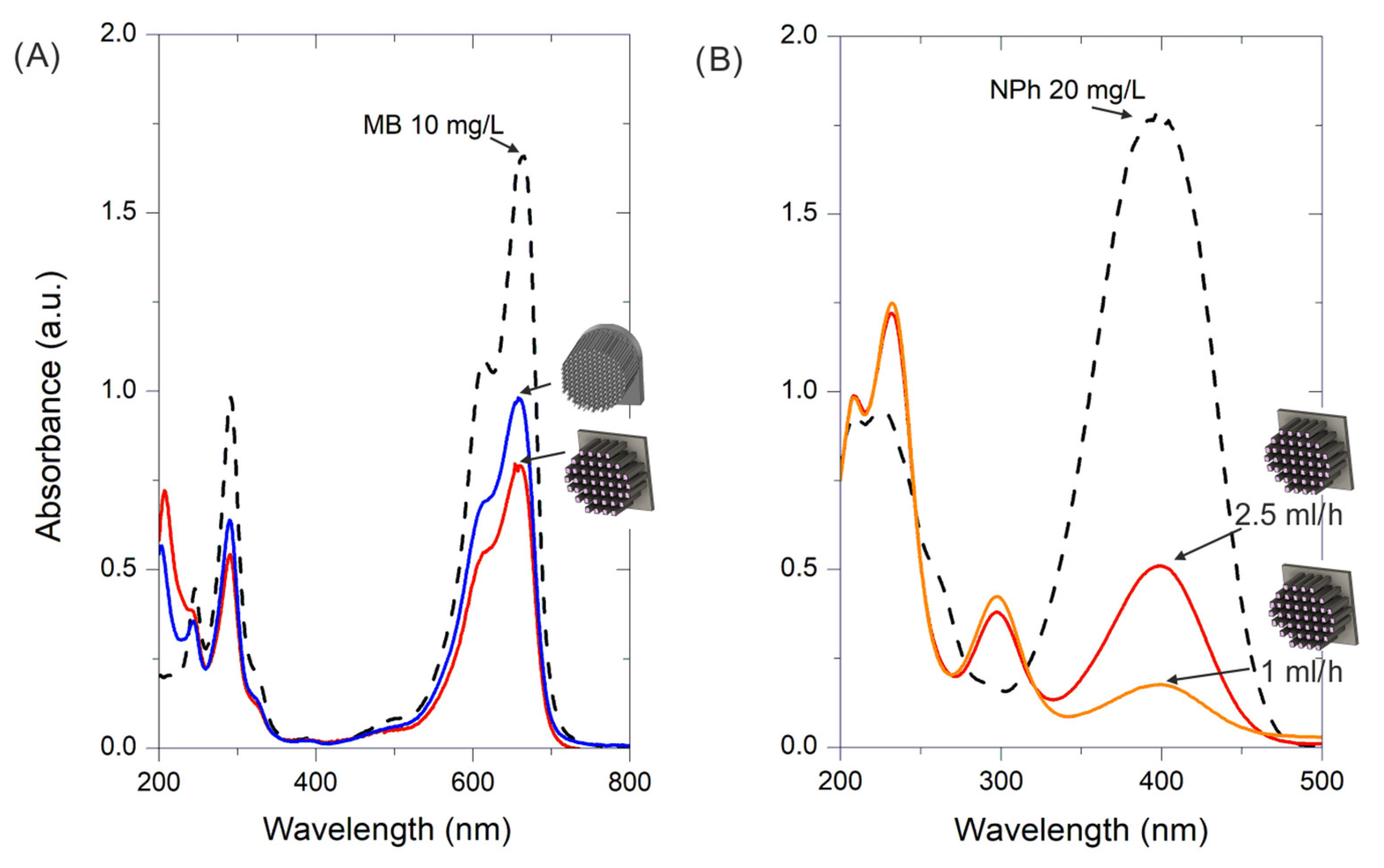
2.2.1. Photocatalytic Degradation of Methylene Blue (MB)

Following our previous experiences in photocatalytic applications for water pollutant removal, a 3 wt. % Cu (Cu0.03/TiO2) catalyst was selected for MB degradation [27]. The reactors loaded with about 20 mg of the Cu0.03/TiO2 catalyst on their microchannels of 0.8 × 0.8 mm and 0.25 × 0.20 mm were placed in reaction tubes with 12 mm inner diameters. Figure 3A shows the results of the MB degradation at a flow rate of 5 mL/h under steady-state conditions. The best performance, with a photodegradation rate of 1.25 mgMB·gcat−1·L−1 (50% MB degradation according to the absorption peak at λ = 656 nm), was exhibited by the microreactor with wider microchannels (0.8 × 0.8 mm). This can be explained by the much higher fluidic volume (Table 1) available in the reactor with rods of 0.8 × 0.8 mm (768 mm3) than in the one with 0.25 × 0.20 mm size rods (77 mm3). This led to a much higher residence time (tr) of 387 s (6.45 min), compared with 50 s (0.83 min), in favor of the microreactor with wider (and longer) microchannels, which explains its better performance. In addition, other effects cannot be discarded, such as the fact that, according to the SEM images, thicker channel reactors have more homogeneous catalyst layers. Last, but not least, a higher number of smaller microchannels can be also detrimental considering light penetration effects.
Similar Cu-doped TiO2 materials have been described in the literature [28,29] for photocatalytic MB removal but were tested in batch photoreactors. In those stirred reactors, 50% MB degradation was achieved between 5 and 12.5 min. The reaction times were of the same order as the result obtained with the 0.8 × 0.8 mm reactor (residence time 6.45 min), but with the disadvantage of having to separate and recover the catalyst and discontinuous operation. It must be highlighted that the performance of the microreactor with smaller (and shorter) microchannels (37% MB degradation) was also remarkable in spite of the low residence time employed (tr = 0.83 min). This can be attributed to the effect associated with its small dimensions that led to a surface-to-volume ratio (18 mm−1) 3.6 times higher than that of the reactor with larger microchannels (5 mm−1). A higher surface-to-volume ratio is beneficial from the point of view of diffusional mass transfer rate enhancement and irradiation efficiency.

2.2.2. 2-Nitrophenol (2NP) Photohydrogenation to 2-Aminophenol (2AP)

The photohydrogenation (or amination) of 2NP to 2AP was conducted in the microreactor with rods of 0.8 × 0.8 mm to favor light penetration. As shown in Figure 3B, the device that was coated with 30 mg of the 1 wt. % Au on the TiO2 catalyst achieved a 2NP conversion rate of about 90% at a feed flow rate of 1 mL/h in the steady-state condition. The conversion decreased to 75% when the flow rate was increased to 2.5 mL/h. Clearly, the change in conversion is due to the reduction in the hydraulic residence time. Comparing these results with those of our previous study carried out with flat serpentine-shaped microreactors [26], the conversions achieved in the multirod configuration were lower, which can be attributed to poorer accessibility to light in this case. In contrast, the tubular multirod design is more compact, easier to implement in conventional tube reactors, and makes it possible to connect the microreactors needed to achieve the required conversion for a given application using a series configuration.

2.2.3. Lignin Depolymerization

Lignin is a polymeric natural compound present in lignocellulosic materials such as wood. It is mainly produced as waste from paper manufacturing processes during some chemical treatments to obtain cellulose. Although a large part of lignin waste is used as a bioenergy source in the manufacturing process, nowadays, lignin has become an attractive by-product because its potential as feedstock for the production of high-value-added chemical precursors (aromatic building blocks of low molecular weight) through depolymerization for use in the bio-based chemical industry [30,31]. One of the main challenges of catalytic lignin depolymerization is the recovery of the catalyst from the final products. Therefore, separating the stages of lignin extraction and processing and using structured heterogeneous catalysts is very appealing. Table 2 includes the results obtained in this work using a microreactor with microchannels of 0.8 × 0.8 mm containing 9.2 mg of β-Mo2C/AC catalyst, or 300 mg of the catalyst arranged in a fixed bed of particles in series after the wood bed (see Section 2.2.4).
The yield of phenolic monomers resulting from the fresh catalysts was twice higher when using the microchannel reactor than in the fixed bed when the reaction was run at 195 °C and 3.6 MPa. Furthermore, given the very different amounts of catalyst used in each case, the yield per gram of catalysts was much higher (almost two orders of magnitude) when the silicone monolith was employed. However, the performance of the microreactor worsened after successive reaction cycles until it stabilized at a yield of 10%. After the fifth cycle, the microreactor was removed from the tube for examination and was found to be damaged due to the swelling effect induced by ethanol under harsh reaction conditions. This problem was not observed when ethanol was circulated at room temperature in the microreactor. A partial collapse of the fluidic structure took place, resulting in an important increase in the pressure drop. It is clear that, when using some organic solvents with PDMS, microreactor swelling effects have to be taken into account in MSR design [32]. Specific studies must be carried out to know the deformation that will occur for any solvent at the reaction temperature and consequently redesign the size of the channels to avoid blockages.

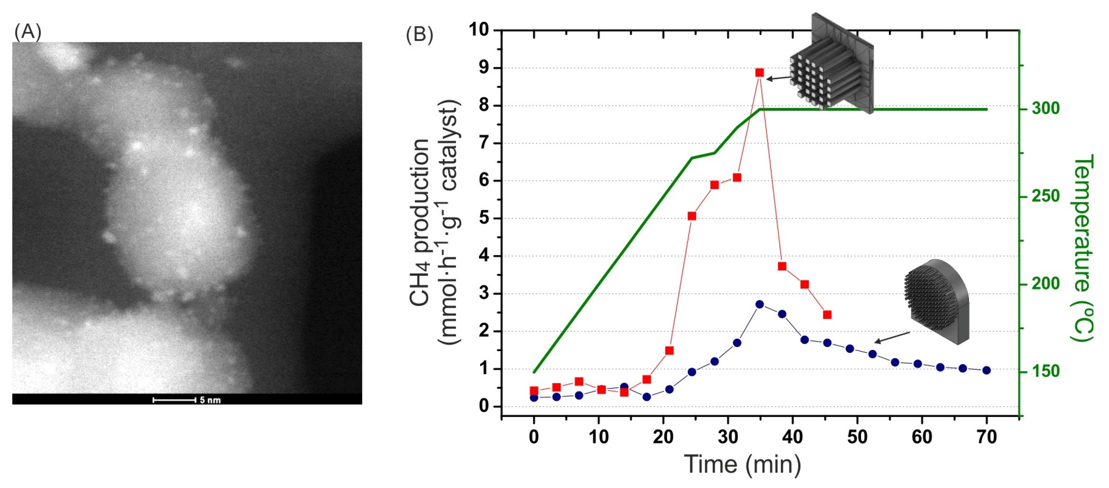
2.2.4. CO2 Hydrogenation to CH4

The direct hydrogenation of CO2 with hydrogen of renewable origin to produce fuels and/or chemicals with a low carbon footprint is a very interesting approach to mitigate global warming and favor the penetration of renewables in the energy mix [33]. Within this context, the Sabatier reaction, i.e., CO2 hydrogenation to CH4 (CO2 methanation) has gained a renewed interest [34]. Thermodynamic limitations dictate that CO2 methanation has to be carried out at relatively low temperatures (e.g., 300–350 °C); hence, a very active catalyst and a reactor allowing the full exploitation of its intrinsic activity are highly desirable. Therefore, MS reactors have a high potential to play an important role in CO2 hydrogenation processes, especially for decentralized CO2 valorization and CH4 production. In recent years, the use of hybrid CO2 methanation catalysts combining photo- and thermal activity is being thoroughly investigated with the aim of giving rise to a solar energy-driven process. The catalytic materials proposed for this purpose are based on Ni, Ru, or Rh nanoparticles highly dispersed on active supports such as semiconductor oxides (TiO2, CeO2, ZrO2) [35], perovskites [36], zeolites [37], MOF-derived materials [38], or graphene [39].
In the present work, 2 wt. % Ru on TiO2 was selected as the catalyst and incorporated into the silicone monolithic microreactors. Ru precursor salt was added to TiO2 and reduced following the amino acid method [40,41]. As can be seen in Figure 4A, the as-deposited Ru nanoparticles presented a narrow size distribution (1.5 ± 0.2 nm) and were homogeneously dispersed on the TiO2 support. Two microreactors with channels of 0.8 × 0.8 mm and 0.20 × 0.25 mm containing approximately 20 mg of catalyst were employed to conduct dynamic CO2 hydrogenation experiments at temperatures ranging from 150 °C to 300 °C, a feed flow rate of 5 N mL/min, and H2/CO2 molar ratios of 4 and 1 atm. Before the methanation tests, catalyst reduction treatment at 150 °C was conducted under a flow of H2. As depicted in Figure 4B, the performance of the microreactor with narrower channels was lower than the microreactor with channels of 0.8 × 0.8 mm that reached a CH4 production of 8.9 mmol h−1 gcatalyst−1 at 300 °C, with a CO2 conversion rate of 8% and CH4 selectivity of 85%. The CH4 production achieved for the best microreactor is slightly lower than the values reported in the literature for similar experiments [42,43]. As explained in Section 2.2.1, the different performances of the two microreactors can be due to the different residence times and the more homogeneous catalyst layer obtained in the widest microchannels, among other factors. As it can be clearly observed, the CH4 production markedly decreased with time on stream when the temperature was kept constant at 300 °C, which is attributed to catalyst deactivation. Although no physical damage to the reactor was observed with the naked eye after the 300 °C reaction, there is a possibility that the PDMS was partially degraded and poisoned the catalyst, thus causing deactivation. This would result in lower activity and a rapid decrease in CH4 production, as was observed. Metallic catalysts are very sensitive to deactivation through poisoning and carbon-species deposits that can be accentuated by the volatile compounds resulting from PDMS degradation [44,45]. This possibility is under consideration and must be carefully investigated through the post-analysis of the used catalyst.

3. Materials and Methods

3.1. Microreactor Fabrication Protocol

The procedure followed to fabricate the multichannel silicone microreactors was based on the scaffold-removal method described by Saggiomo and Velders [20], but with an additional step to incorporate the heterogeneous catalysts described in our previous work [26]. Briefly (see Figure 5), (i) a multirod negative mold was designed using CAD (Fusion 360), laminated (Cura Ultimaker), and 3D-printed (Ultimaker S3) in ABS (SMARTFIL® Natural ABS); (ii) catalytic nanoparticles were incorporated to the ABS mold through dip coating; (iii) the ABS mold was placed in a tubular holder of a suitable size, where PDMS (Sylgard 184 Dowsil) was poured and cured; (iv) the ABS–PDMS piece was demolded, and ABS scaffold was removed using warm acetone to release the channels microstructure; (v) finally, a multichannel reactor (or several of them) was placed in the experimental setup. The deposition of the nanoparticulated catalysts over the surface of the ABS molds was carried out through dip coating (ND-DC dip coater—Nadetech Innovations). A stable suspension was prepared by mixing the catalytic nanoparticles, propan-2-ol (Scharlab), and deionized H2O in a 1:50:50 (w/w/w) ratio, and via sonication for 10 min. Prior to coating, the ABS scaffold was subjected to plasma treatment (corona discharge—BD-20AC ElectroTechnic Products) for 1 min in order to improve its wettability. The mold was subsequently dip-coated into the colloidal suspension employing immersion and withdrawal rates of 100 mm min−1 and 10 mm min−1, respectively, and the mold was kept submerged for 10 s. After coating, the device was dried in an oven at 100 °C for 30 min, and the procedure was repeated several times until the desired catalyst load (around 20 mg per mold) was achieved.
Liquid PDMS was prepared by mixing a prepolymer (elastomer) and a curing agent (cross-linker) with a 5:1 (w/w) ratio and outgassing under vacuum (20 mmHg) until no bubble formation was observed. That formulation was selected in order to increase the thermal stability of PDMS up to 350 °C [19], which was needed for some of the selected test reactions. The ABS scaffold coated with the catalyst was placed in a container, and PDMS was poured until it was completely covered by the liquid. Degassing was repeatedly applied to assure that bubbles were completely removed. Afterward, PDMS was cured in an oven at 100 °C for 15 min, and the resulting block was peeled off from the container tube and cut to the final dimensions removing PDMS in excess. Finally, the ABS–PDMS block was submerged in acetone (Scharlab) at 50 °C for 12 h and sonicated several times to facilitate the dissolution of ABS while the microchannels were formed [25]. In order to assure the complete removal of ABS, fresh acetone was passed through the channels repeatedly, and a final vigorous cleaning with propan-2-ol and later with deionized water was applied.

3.2. Catalytic Materials and Experiments

Au, Cu, and Ru supported on titania and Mo2C were selected as catalytic materials to be integrated into the multichannel microreactors:
(i)
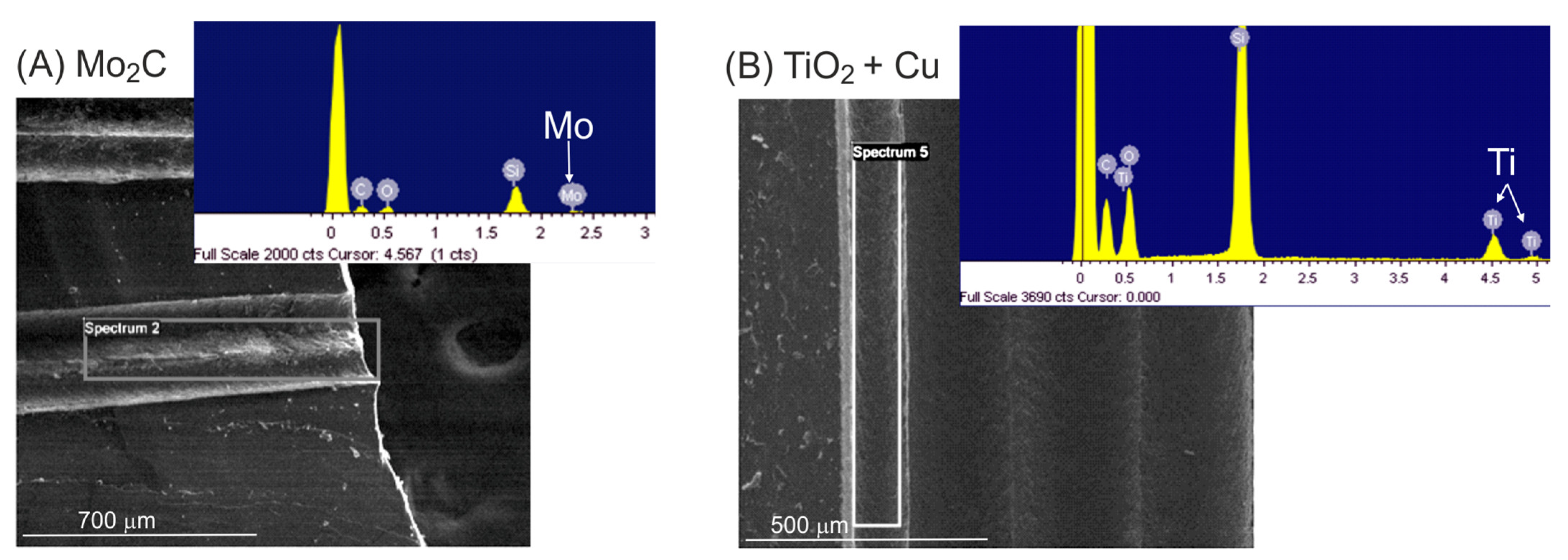
Cu (3 wt. %) on TiO2 was prepared via flame spray pyrolysis following the procedure described in a previous study [27] and was selected for the photocatalytic degradation of methylene blue (MB) in water (10 mg/L). The microreactors containing the catalyst were placed in a quartz reaction tube (10 mm inner diameter), and an aqueous MB dissolution was fed using a syringe pump at flow rates ranging from 0.5 mL/h to 5 mL/h at room temperature. Illumination was performed with two UV LEDs (1200 mW radiant flux, 365 nm, Engin LZ1-10U600) placed on opposite sides with the reactor in the middle at a distance of 1 cm from each LED. The liquid effluent was collected in a cuvette, and the MB degradation reaction was monitored via UV–Vis spectroscopy (Flame Ocean Optics) through the analysis of the characteristic absorption peak at a wavelength (λ) of 665 nm.
(ii)
Au (1 wt. %) on the TiO2 (TECNAN, Los Arcos, Spain) catalyst was prepared as described in a previous study, in which the photohydrogenation procedure of 2-nitrophenol (2NP) to 2-aminophenol (2AP) reaction was also reported [26]. An aqueous solution of 2NP (Aldrich, 20 mg/L) was treated with sodium borohydride (1 g/L) as a reducing agent. The experimental setup was the same as the one used for MB degradation, though the reaction evolution was monitored through the analysis of the characteristic absorption band at λ = 400 nm.
(iii)
β-Mo2C on activated charcoal (AC) was prepared through the incipient wetness impregnation of the support using aqueous ammonium heptamolybdate tetrahydrate until achieving a nominal Mo content of 35 wt. %, followed by carboreduction as described by Wu et al. [46]. Lignin depolymerization was carried out in a two-bed in-series tubular flow reactor (½ inch o.d. stainless steel tube with 10.0 mm i.d. and 100 mm of length). The first bed contained the solid Poplar sawdust feedstock (ca. 980 mg Populus sp., dp <500 μm), separated by glass wool from the second bed that was charged with β-Mo2C/AC particles (typically 300 mg) or with the microreactor containing the catalyst. The tube was placed inside a reaction oven (JASCO RO-4068), and ethanol was circulated at 9 mL/min using an HPLC pump (JASCO PU-1585). A back-pressure regulator (JASCO BP-1580-81) allowed for controlling the reaction pressure at 3.6 MPa-g. Liquid product collection was conducted at atmospheric pressure and room temperature, and its composition was analyzed via gas chromatography and HPLC as described elsewhere [47]. The reaction temperature was fixed at 195 °C, and the temperature inside the catalyst bed was monitored by means of a K-type thermocouple (1319 A, RS Amidata). In this way, the semicontinuous reductive catalytic fractionation (RCF) of lignin was divided into two separate processes: (1) the extraction of the polymer from the raw material with ethanol, and (2) subsequent lignin depolymerization in ethanol over β-Mo2C/AC catalyst.
(iv)
Ru (2 wt. %) on the TiO2 (P25 Evonik) catalyst was prepared following the amino-acid-based method described in [41] using RuCl3 (Aldrich) as the Ru precursor, NaBH4 (Aldrich) as the reducing agent, and aminobutyric acid (ABA) (Aldrich) as the capping agent to control the size of the Ru nanoparticles. The actual Ru content was 1.6 wt. %, as determined by using ICP-MS (inductively coupled plasma mass spectroscopy). High Ru dispersion was confirmed by the finding that CO chemisorption gave a value of 72.9%. Temperature-programmed reduction (TPR) patterns showed two reduction events, with a main peak at 90 °C corresponding to 71% of the H2 consumption and another peak at 140 °C. The overall degree of reduction was 20%. CO2 methanation experiments were carried out in a quartz tubular reactor (10 mm inner diameter) placed in a programmable oven with temperature control through a PT100 probe located in contact with the MS reactor. The experiments were carried out with a feed stream of 5 N-mL/min with a H2/CO2 molar ratio of 4 (1 atm). Prior to the reaction, the catalyst was activated through a reduction process in 150 °C flowing H2 (10 N-mL/min) at 1 atm.

4. Conclusions

Monolithic microreactors can be easily fabricated in PDMS following the scaffold-removal method. Different patterns can be printed and fabricated by adjusting the nozzle diameter and printing parameters (temperature and printing velocity). Microchannel dimensions of 0.2 mm diameter and 20 mm length can be achieved. Longer channels were found to have bridging problems and require a careful selection of the printing parameters. High channel densities (>30%) have the risk of channel intercrossing and weakness of the structure. The key feature of the reported fabrication procedure in this study is the incorporation of the catalyst into the ABS scaffold and its subsequent incorporation into the silicone walls. The atmospheric plasma treatment applied to improve wettability and improve catalyst adhesion showed limitations, so using a vacuum plasma treatment to apply an intermediate coating layer (i.e., colloidal silica) is recommended.
Catalytic tests showed that, in the case of photocatalytic applications, good microreactor performance was found, though designs with small channel dimensions led to worse results, probably due to both inefficient illumination and heterogeneous catalyst incorporation. Hence, the performance of the microdevice relies on the trade-off between dimension and density of the channels, which must be optimize for each application. The chemical stability of PDMS is another important issue, as demonstrated in the case of lignin depolymerization. Although the catalytic performance of the microreactor was initially satisfactory in comparison with a fixed-bed reactor, the PDMS swelling caused by ethanol at a high temperature damaged the fluidic structure. Finally, as for a gas-phase application such as CO2 hydrogenation, no physical degradation was observed after operation at 300 °C, for which the possibility of catalyst deactivation caused by the PDMS substrate has to be investigated.
In summary, the proposed silicone monolith microreactors fabricated by using the scaffold-removal method are available for reactions under very different conditions, although under some limitations such as the use of organic solvents and high reaction temperature. For reactions under organic solvents, PDMS swelling must be taken into account to redesign the channel’s dimension to avoid blockage, and in the case of high-temperature applications (up to 300 °C), the degradation of the PDMS can influence the results. PDMS MSRs are best suited for soft conditions involving aqueous media and low temperatures, for example, in advanced wastewater treatments, or when considering PDMS biocompatibility, these kinds of reactors could be useful in enzymatic catalysis [48,49].

Author Contributions

Conceptualization and methodology, I.P., F.B., A.C. and L.M.G.; investigation and data curation, A.I.-d.-G., M.I., M.M., F.A., D.S. and I.P.; writing—review and editing, F.A., I.P., F.B., A.C. and L.M.G.; funding acquisition, I.P. and L.M.G. All authors have read and agreed to the published version of the manuscript.

Funding

Financial support was received from Spanish Agencia Estatal de Investigación and Spanish Ministerio de Ciencia e Innovación MCIN/AEI/10.13039/501100011033/ and FEDER “Una manera de hacer Europa” (grants PID2019-106687RJ-I00/AEI/10.13039/501100011033 and PID2021-127265OB-C21) as well as from Plan de Recuperación, Transformación y Resiliencia and NextGenerationEU (grants PLEC2022-009221 and TED2021-130846B-100), and Gobierno de Navarra grant PC091-092 FOREST2+ which are gratefully acknowledged. The Spanish Ministerio de Universidades fellowship FPU 18/01877 was granted to M.I. The Universidad Pública de Navarra predoctoral fellowship was granted to M.M. L.M. Gandía thanks Banco de Santander and Universidad Pública de Navarra for their financial support under the “Programa de Intensificación de la Investigación 2018” initiative.

Acknowledgments

Authors acknowledge the use of instrumentation as well as the technical advice provided by the National Facility ELECMI ICTS, node Laboratorio de Microscopias Avanzadas (LMA) at Universidad de Zaragoza.

Conflicts of Interest

The authors declare no conflict of interest.

References

  1. Renken, A. Microstructured Reactors for Heterogeneous Catalytic Processes. Springer Ser. Chem. Phys. 2004, 75, 521–542. [Google Scholar]
  2. Jähnisch, K.; Hessel, V.; Löwe, H.; Baerns, M. Chemistry in Microstructured Reactors. Angew. Chem. Int. Ed. 2004, 43, 406–446. [Google Scholar] [CrossRef] [PubMed]
  3. Venvik, H.J.; Yang, J. Catalysis in Microstructured Reactors: Short Review on Small-Scale Syngas Production and Further Conversion into Methanol, DME and Fischer-Tropsch Products. Catal. Today 2017, 285, 135–146. [Google Scholar] [CrossRef]
  4. Kolb, G. Review: Microstructured Reactors for Distributed and Renewable Production of Fuels and Electrical Energy. Chem. Eng. Process. Process Intensif. 2013, 65, 1–44. [Google Scholar] [CrossRef]
  5. Reyero, I.; Moral, A.; Bimbela, F.; Radosevic, J.; Sanz, O.; Montes, M.; Gandía, L.M. Metallic Monolithic Catalysts Based on Calcium and Cerium for the Production of Biodiesel. Fuel 2016, 182, 668–676. [Google Scholar] [CrossRef]
  6. Almeida, L.C.; Echave, F.J.; Sanz, O.; Centeno, M.A.; Arzamendi, G.; Gandía, L.M.; Sousa-Aguiar, E.F.; Odriozola, J.A.; Montes, M. Fischer–Tropsch Synthesis in Microchannels. Chem. Eng. J. 2011, 167, 536–544. [Google Scholar] [CrossRef]
  7. Das, S.; Srivastava, V.C. Microfluidic-Based Photocatalytic Microreactor for Environmental Application: A Review of Fabrication Substrates and Techniques, and Operating Parameters. Photochem. Photobiol. Sci. 2016, 15, 714–730. [Google Scholar] [CrossRef]
  8. Yusuf, A.; Garlisi, C.; Palmisano, G. Overview on Microfluidic Reactors in Photocatalysis: Applications of Graphene Derivatives. Catal. Today 2018, 315, 79–92. [Google Scholar] [CrossRef]
  9. Suryawanshi, P.L.; Gumfekar, S.P.; Bhanvase, B.A.; Sonawane, S.H.; Pimplapure, M.S. A Review on Microreactors: Reactor Fabrication, Design, and Cutting-Edge Applications. Chem. Eng. Sci. 2018, 189, 431–448. [Google Scholar] [CrossRef]
  10. Zhang, L.; Zhu, Z.; Liu, B.; Li, C.; Yu, Y.; Tao, S.; Li, T. Fluorescent Fluid in 3D-Printed Microreactors for the Acceleration of Photocatalytic Reactions. Adv. Sci. 2019, 6, 1900583. [Google Scholar] [CrossRef]
  11. Anciaux, S.K.; Geiger, M.; Bowser, M.T. 3D Printed Micro Free-Flow Electrophoresis Device. Anal. Chem. 2016, 88, 7675–7682. [Google Scholar] [CrossRef] [PubMed]
  12. Neumaier, J.M.; Madani, A.; Klein, T.; Ziegler, T. Low-Budget 3D-Printed Equipment for Continuous Flow Reactions. Beilstein J. Org. Chem. 2019, 15, 558–566. [Google Scholar] [CrossRef] [PubMed] [Green Version]
  13. Castedo, A.; Mendoza, E.; Angurell, I.; Llorca, J. Silicone Microreactors for the Photocatalytic Generation of Hydrogen. Catal. Today 2016, 273, 106–111. [Google Scholar] [CrossRef] [Green Version]
  14. Saggiomo, V. 3D Printed Devices for Catalytic Systems. In Catalyst Immobilization; Wiley: Hoboken, NJ, USA, 2020; pp. 369–408. [Google Scholar]
  15. Munirathinam, R.; Huskens, J.; Verboom, W. Supported Catalysis in Continuous-Flow Microreactors. Adv. Synth. Catal. 2015, 357, 1093–1123. [Google Scholar] [CrossRef]
  16. Mehla, S.; Das, J.; Jampaiah, D.; Periasamy, S.; Nafady, A.; Bhargava, S.K. Recent Advances in Preparation Methods for Catalytic Thin Films and Coatings. Catal. Sci. Technol. 2019, 9, 3582–3602. [Google Scholar] [CrossRef]
  17. Almeida, L.C.; Echave, F.J.; Sanz, O.; Centeno, M.A.; Odriozola, J.A.; Montes, M. Washcoating of Metallic Monoliths and Microchannel Reactors. Stud. Surf. Sci. Catal. 2010, 175, 25–33. [Google Scholar]
  18. McDonald, J.C.; Whitesides, G.M. Poly(Dimethylsiloxane) as a Material for Fabricating Microfluidic Devices. Acc. Chem. Res. 2002, 35, 491–499. [Google Scholar] [CrossRef]
  19. Ren, K.; Zheng, Y.; Dai, W.; Ryan, D.; Fung, C.Y.; Wu, H. Soft-Lithography-Based High Temperature Molding Method to Fabricate Whole Teflon Microfluidic Chips. In Proceedings of the 14th International Conference on Miniaturized Systems for Chemistry and Life Sciences, 2010, MicroTAS, Groningen, The Netherlands, 3–7 October 2010; p. 554. [Google Scholar]
  20. Saggiomo, V.; Velders, A.H. Simple 3D Printed Scaffold-Removal Method for the Fabrication of Intricate Microfluidic Devices. Adv. Sci. 2015, 2, 1500125. [Google Scholar] [CrossRef]
  21. Yamashita, T.; Yasukawa, K.; Yunoki, E. Fabrication of a Polydimethylsiloxane Fluidic Chip Using a Sacrificial Template Made by Fused Deposition Modeling 3D Printing and Application for Flow-Injection Analysis. Anal. Sci. 2019, 35, 769–775. [Google Scholar] [CrossRef] [Green Version]
  22. Alkayyali, T.; Ahmadi, A. Fabrication of Microfluidic Chips Using Controlled Dissolution of 3D Printed Scaffolds. J. Appl. Polym. Sci. 2020, 137, 49524. [Google Scholar] [CrossRef]
  23. Montazerian, H.; Mohamed, M.G.A.; Montazeri, M.M.; Kheiri, S.; Milani, A.S.; Kim, K.; Hoorfar, M. Permeability and Mechanical Properties of Gradient Porous PDMS Scaffolds Fabricated by 3D-Printed Sacrificial Templates Designed with Minimal Surfaces. Acta Biomater. 2019, 96, 149–160. [Google Scholar] [CrossRef] [PubMed]
  24. Tang, W.; Liu, H.; Zhu, L.; Shi, J.; Li, Z.; Xiang, N.; Yang, J. Fabrication of Different Microchannels by Adjusting the Extrusion Parameters for Sacrificial Molds. Micromachines 2019, 10, 544. [Google Scholar] [CrossRef] [PubMed]
  25. Chen, P.C.; Chou, C.C. Fabrication of a Nonplanar Microfluidics by Using Sonication-Assisted Dissolution Technique. In Proceedings of the NEMS 2018—13th Annual IEEE International Conference on Nano/Micro Engineered and Molecular Systems, Singapore, 22–26 April 2018; Institute of Electrical and Electronics Engineers Inc.: Piscataway, NJ, USA, 2018; pp. 421–424. [Google Scholar]
  26. Pellejero, I.; Clemente, A.; Reinoso, S.; Cornejo, A.; Navajas, A.; Vesperinas, J.J.; Urbiztondo, M.A.; Gandía, L.M. Innovative Catalyst Integration on Transparent Silicone Microreactors for Photocatalytic Applications. Catal. Today 2022, 383, 164–172. [Google Scholar] [CrossRef]
  27. Cabrera, A.; Pellejero, I.; Oroz-Mateo, T.; Salazar, C.; Navajas, A.; Fernández-Acevedo, C.; Gandía, L.M. Three-Dimensional Printing of Acrylonitrile Butadiene Styrene Microreactors for Photocatalytic Applications. Ind. Eng. Chem. Res. 2020, 59, 20686–20692. [Google Scholar] [CrossRef]
  28. Mingmongkol, Y.; Trinh, D.T.T.; Phuinthiang, P.; Channei, D.; Ratananikom, K.; Nakaruk, A.; Khanitchaidecha, W. Enhanced Photocatalytic and Photokilling Activities of Cu-Doped TiO2 Nanoparticles. Nanomaterials 2022, 12, 1198. [Google Scholar] [CrossRef]
  29. Tichapondwa, S.M.; Newman, J.P.; Kubheka, O. Effect of TiO2 Phase on the Photocatalytic Degradation of Methylene Blue Dye. Phys. Chem. Earth Parts A/B/C 2020, 118–119, 102900. [Google Scholar] [CrossRef]
  30. Nguyen, L.T.; Phan, D.P.; Sarwar, A.; Tran, M.H.; Lee, O.K.; Lee, E.Y. Valorization of Industrial Lignin to Value-Added Chemicals by Chemical Depolymerization and Biological Conversion. Ind. Crops Prod. 2021, 161, 113219. [Google Scholar] [CrossRef]
  31. Welker, C.; Balasubramanian, V.; Petti, C.; Rai, K.; DeBolt, S.; Mendu, V. Engineering Plant Biomass Lignin Content and Composition for Biofuels and Bioproducts. Energies 2015, 8, 7654–7676. [Google Scholar] [CrossRef] [Green Version]
  32. Lee, J.N.; Park, C.; Whitesides, G.M. Solvent Compatibility of Poly(Dimethylsiloxane)-Based Microfluidic Devices. Anal. Chem. 2003, 75, 6544–6554. [Google Scholar] [CrossRef]
  33. Ramirez, A.; Sarathy, S.M.; Gascon, J. CO2 Derived E-Fuels: Research Trends, Misconceptions, and Future Directions. Trends Chem. 2020, 2, 785–795. [Google Scholar] [CrossRef]
  34. Vogt, C.; Monai, M.; Kramer, G.J.; Weckhuysen, B.M. The Renaissance of the Sabatier Reaction and Its Applications on Earth and in Space. Nat. Catal. 2019, 2, 188–197. [Google Scholar] [CrossRef]
  35. Kim, A.; Debecker, D.P.; Devred, F.; Dubois, V.; Sanchez, C.; Sassoye, C. CO2 Methanation on Ru/TiO2 Catalysts: On the Effect of Mixing Anatase and Rutile TiO2 Supports. Appl. Catal. B Environ. 2018, 220, 615–625. [Google Scholar] [CrossRef]
  36. Mateo, D.; Maity, P.; Shterk, G.; Mohammed, O.F.; Gascon, J. Tunable Selectivity in CO2 Photo-Thermal Reduction by Perovskite-Supported Pd Nanoparticles. ChemSusChem 2021, 14, 5525–5533. [Google Scholar] [CrossRef] [PubMed]
  37. Bando, K.K.; Arakawa, H.; Ichikuni, N. CO2 Hydrogenation over Micro- and Mesoporous Oxides Supported Ru Catalysts. Catal. Lett. 1999, 60, 125–132. [Google Scholar] [CrossRef]
  38. Khan, I.S.; Mateo, D.; Shterk, G.; Shoinkhorova, T.; Poloneeva, D.; Garzón-Tovar, L.; Gascon, J. An Efficient Metal–Organic Framework-Derived Nickel Catalyst for the Light Driven Methanation of CO2. Angew. Chem. Int. Ed. 2021, 60, 26476–26482. [Google Scholar] [CrossRef]
  39. Mateo, D.; Albero, J.; García, H. Graphene Supported NiO/Ni Nanoparticles as Efficient Photocatalyst for Gas Phase CO2 Reduction with Hydrogen. Appl. Catal. B Environ. 2018, 224, 563–571. [Google Scholar] [CrossRef]
  40. Yu, J.W.; Li, W.Z.; Zhang, T.; Ma, D.; Zhang, Y.W. Ruthenium Nanoclusters Dispersed on Titania Nanorods and Nanoparticles as High-Performance Catalysts for Aqueous-Phase Fischer–Tropsch Synthesis. Catal. Sci. Technol. 2016, 6, 8355–8363. [Google Scholar] [CrossRef]
  41. Koh, T.; Koo, H.M.; Yu, T.; Lim, B.; Bae, J.W. Roles of Ruthenium-Support Interactions of Size-Controlled Ruthenium Nanoparticles for the Product Distribution of Fischer-Tropsch Synthesis. ACS Catal. 2014, 4, 1054–1060. [Google Scholar] [CrossRef]
  42. Kim, A.; Sanchez, C.; Patriarche, G.; Ersen, O.; Moldovan, S.; Wisnet, A.; Sassoye, C.; Debecker, D.P. Selective CO2 Methanation on Ru/TiO2 Catalysts: Unravelling the Decisive Role of the TiO2 Support Crystal Structure. Catal. Sci. Technol. 2016, 6, 8117–8128. [Google Scholar] [CrossRef] [Green Version]
  43. Zhou, Z.; Li, J.; You, Z. A Facile TiO2 Containing Oxygen Vacancies and Hydroxyl as a Ru-Loaded Underlay for CO2 Hydrogenation to CH4. Appl. Surf. Sci. 2022, 587, 152856. [Google Scholar] [CrossRef]
  44. Falbo, L.; Visconti, C.G.; Lietti, L.; Szanyi, J. The Effect of CO on CO2 Methanation over Ru/Al2O3 Catalysts: A Combined Steady-State Reactivity and Transient DRIFT Spectroscopy Study. Appl. Catal. B Environ. 2019, 256, 117791. [Google Scholar] [CrossRef]
  45. Ewald, S.; Kolbeck, M.; Kratky, T.; Wolf, M.; Hinrichsen, O. On the Deactivation of Ni-Al Catalysts in CO2 Methanation. Appl. Catal. A Gen. 2019, 570, 376–386. [Google Scholar] [CrossRef]
  46. Wu, K.; Wang, J.; Zhu, Y.; Wang, X.; Yang, C.; Liu, Y.; Liu, C.; Lu, H.; Liang, B.; Li, Y. Supported β-Mo2C on Carbon Materials for Kraft Lignin Decomposition into Aromatic Monomers in Ethanol. Ind. Eng. Chem. Res. 2019, 58, 12602–12610. [Google Scholar] [CrossRef]
  47. Cornejo, A.; Bimbela, F.; Moreira, R.; Hablich, K.; García-Yoldi, Í.; Maisterra, M.; Portugal, A.; Gandía, L.M.; Martínez-Merino, V. Production of Aromatic Compounds by Catalytic Depolymerization of Technical and Downstream Biorefinery Lignins. Biomolecules 2020, 10, 1338. [Google Scholar] [CrossRef]
  48. Ling, F.W.M.; Abdulbari, H.A.; Chin, S.Y. Heterogeneous Microfluidic Reactors: A Review and an Insight of Enzymatic Reactions. ChemBioEng Rev. 2022, 9, 265–285. [Google Scholar] [CrossRef]
  49. Zhu, Y.; Chen, Q.; Shao, L.; Jia, Y.; Zhang, X. Microfluidic Immobilized Enzyme Reactors for Continuous Biocatalysis. React. Chem. Eng. 2020, 5, 9–32. [Google Scholar] [CrossRef]
Figure 1. Fabrication steps of multichannel silicone microreactors: (A) CAD designs, (B) photographs of 3D printed ABS scaffolds, and SEM images of (C) catalyst incorporation on ABS scaffold and (D) cross-section and longitudinal-section of fabricated microchannels.
Catalysts 13 00157 g001
Figure 2. EDX analysis of channel walls to determine the presence of catalysts: (A) Mo2C and (B) Cu/TiO2.
Catalysts 13 00157 g002
Figure 3. (A) The 10 mg/L MB photodegradation at 5 mL/h in two microreactors 0.8 × 0.8 mm and 0.25 × 0.2 mm coated with TiO2-(3% Cu); (B) the 20 mg/L NPh amination process under different flow rates with a microreactor of 0.8 × 0.8 mm coated with TiO2-(1% Au).
Catalysts 13 00157 g003
Figure 4. CO2 hydrogenation using Ru/TiO2 catalyst on microchannel reactors: (A) TEM image of the catalyst; (B) CH4 production during CO2 hydrogenation at 1 atm in the microchannel reactors indicated.
Catalysts 13 00157 g004
Figure 5. Scheme of the fabrication protocol of multichannel silicone microreactors using the “scaffold-removal” method and the incorporation of the catalyst and photographs of the different molds and reactors fabricated.
Catalysts 13 00157 g005
Table 1. Selected scaffold designs and extrusion parameters.
DesignReactor Length-Diameter
(mm)
Rod Dimension
(mm)
Rod Number
(Density %)
Fluidic Volume
(mm3)
Nozzle (mm)Layer HeightPrinting T (°C) and Velocity (mm/s)
Catalysts 13 00157 i00110–2090.2 × 0.25154 (12%)77–1540.250.2255/50
Catalysts 13 00157 i00220140.4 × 0.398 (7.6%)235.20.40.3255/60
Catalysts 13 00157 i00320140.8 × 0.860 (25%)7680.40.2255/60
Catalysts 13 00157 i00420140.8 × 0.3198 (30%)950.40.80.3250/70
Catalysts 13 00157 i00510–15100.8 × 0.832 (26%)204.8–307.20.40.2255/60
Catalysts 13 00157 i00615151.0 × 1.044 (24%)6600.40.2255/60
Table 2. Lignin depolymerization using Mo2C catalyst in multichannel microreactor and fixed bed.
Multichannel MicroreactorFixed Bed
Reaction Cycle NumberPhenolic Monomer Yield (%)Phenolic Monomer Yield (%)/mgcat.Phenolic Monomer Yield (%)Phenolic Monomer Yield (%)/mgcat.
Fresh catalyst262.8313.3 0.044
2151.6312.4 0.041
3101.0919.4 0.065
4101.0915.5 0.052
5101.0913.8 0.046
Disclaimer/Publisher’s Note: The statements, opinions and data contained in all publications are solely those of the individual author(s) and contributor(s) and not of MDPI and/or the editor(s). MDPI and/or the editor(s) disclaim responsibility for any injury to people or property resulting from any ideas, methods, instructions or products referred to in the content.

