
The Effectiveness of Ni-Based Bimetallic Catalysts Supported by MgO-Modified Alumina in Dry Methane Reforming
 ,
,  , and
, and 
Abstract
:1. Introduction
2. Results
2.1. Surface Description
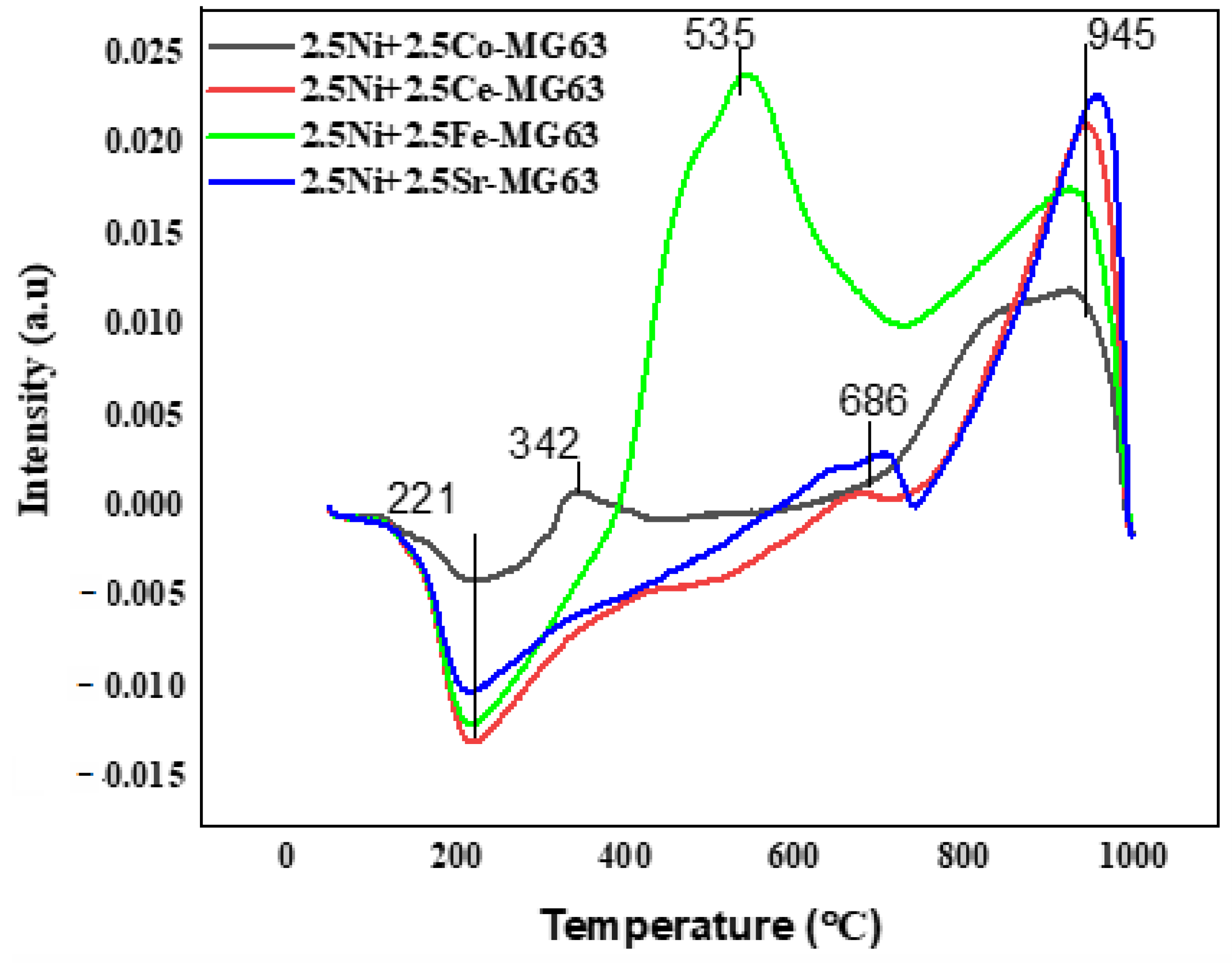
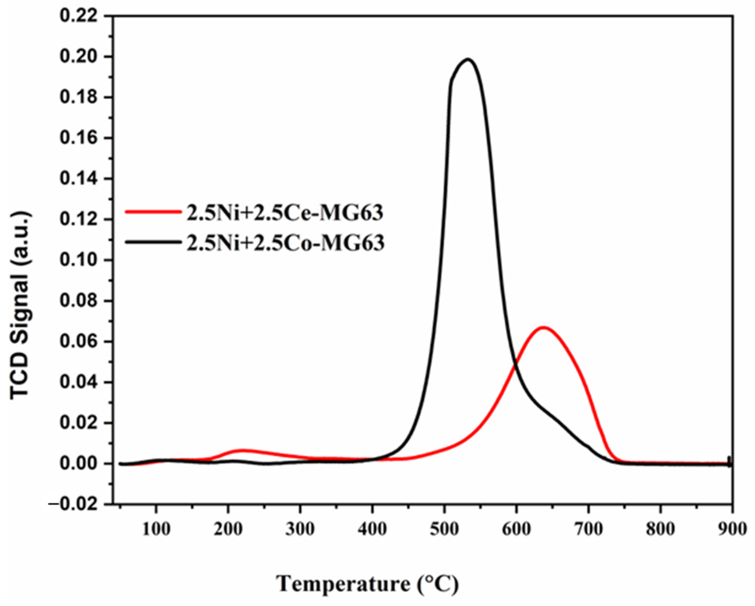
2.2. TPR
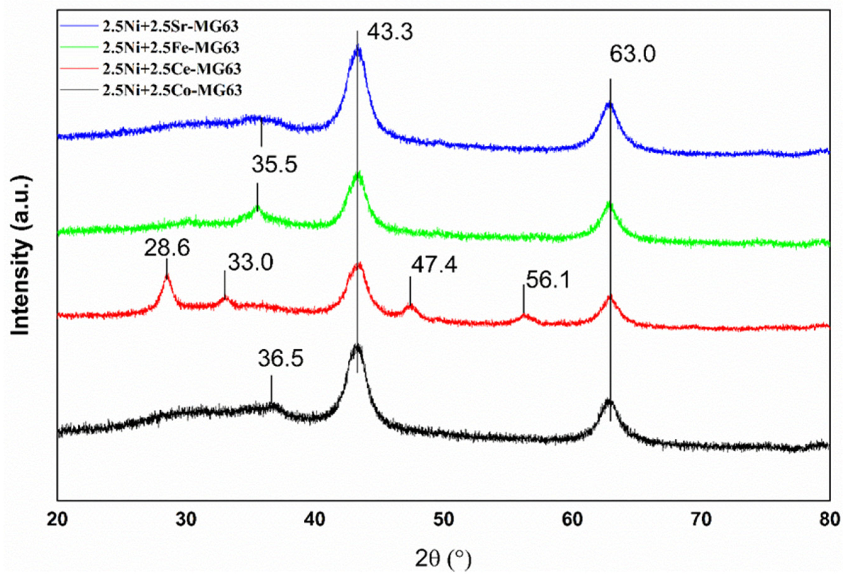
2.3. XRD
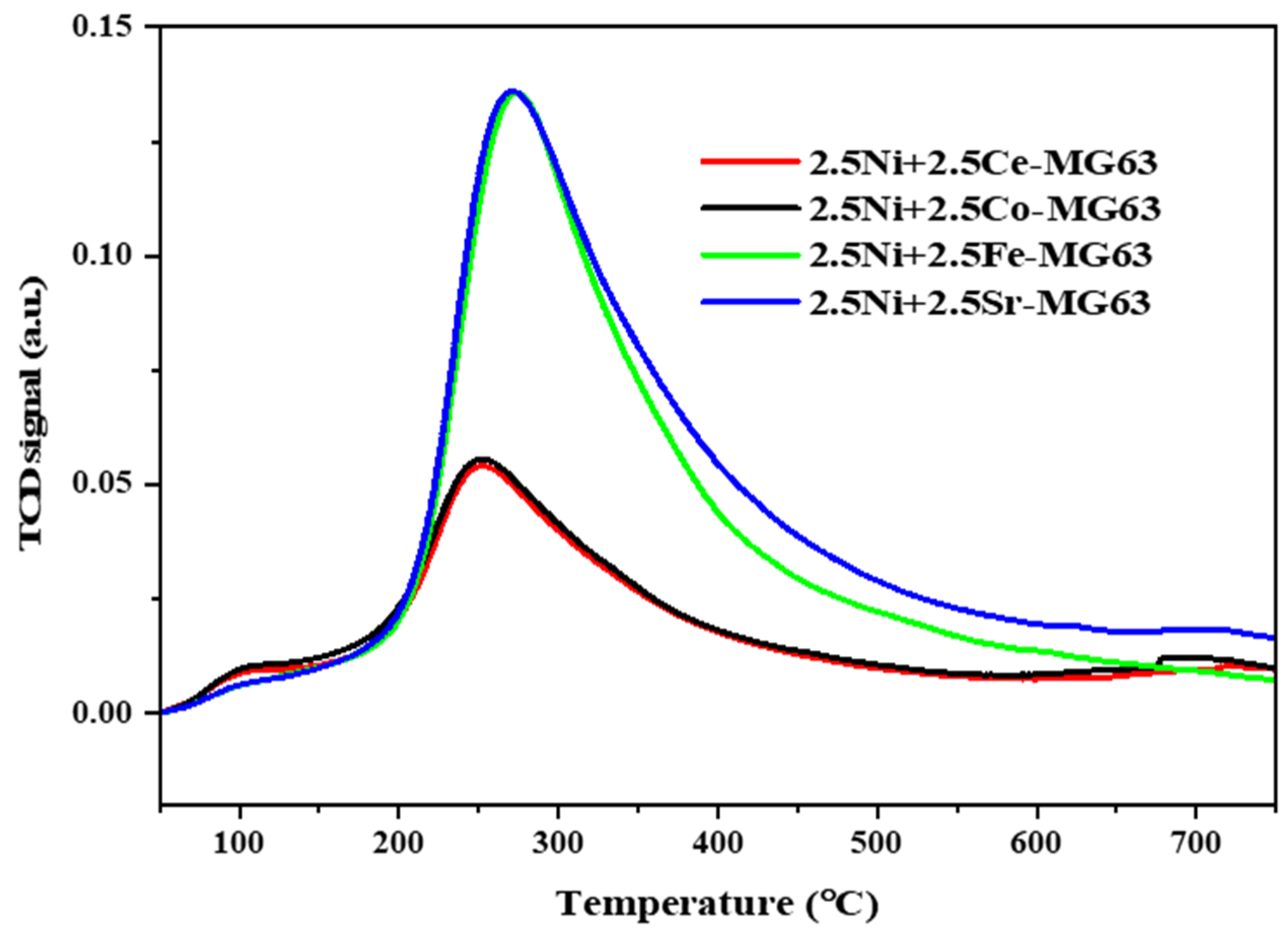
2.4. TPD
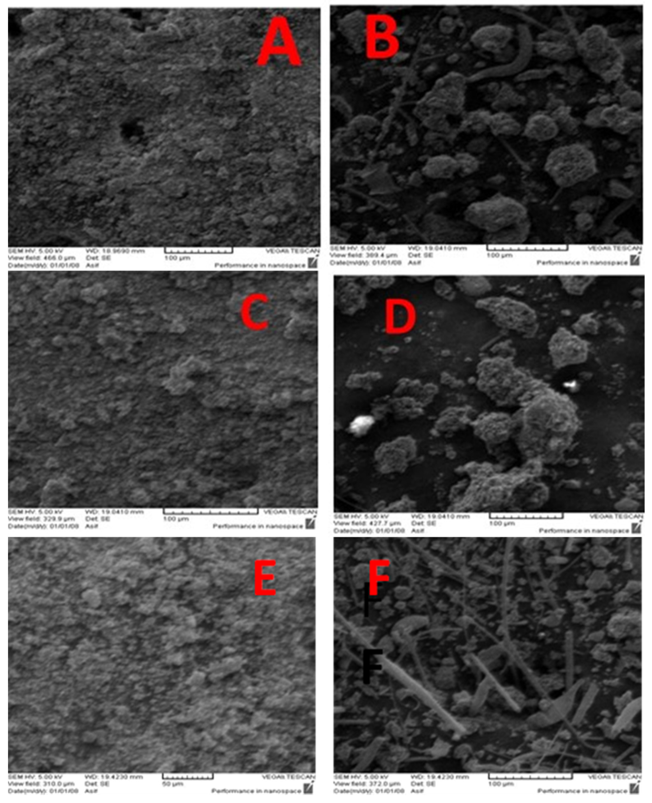
2.5. SEM
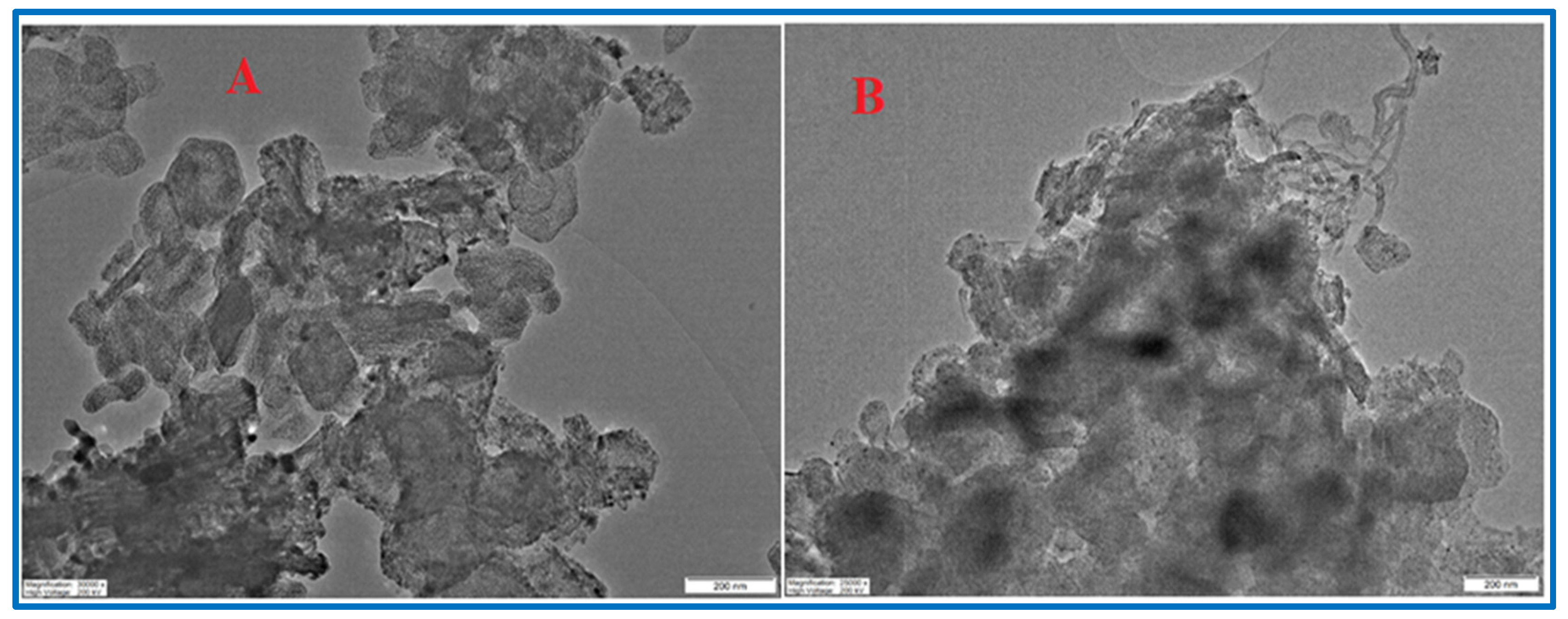
2.6. TEM
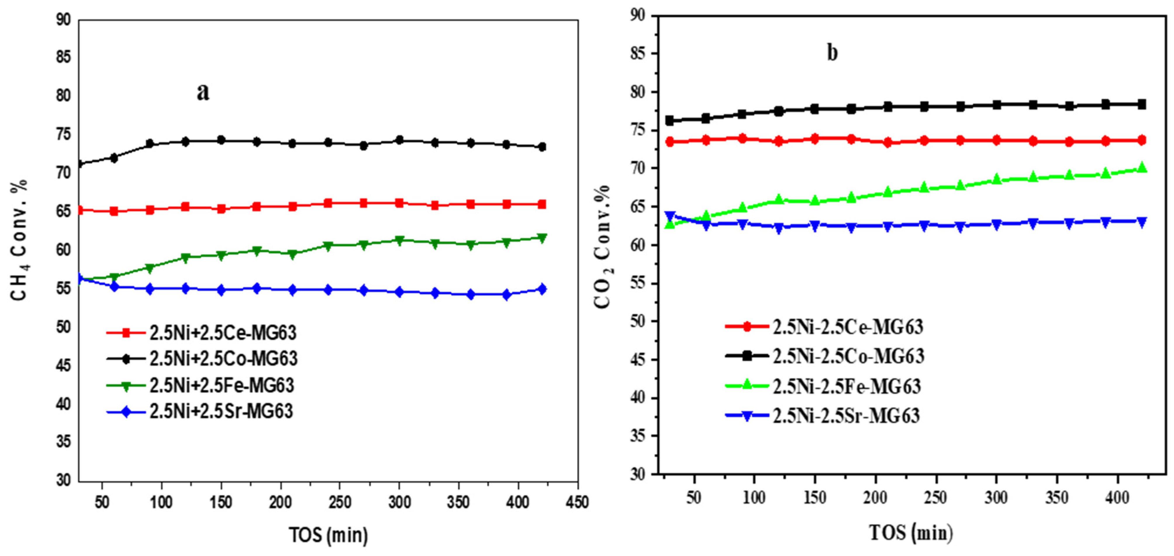
2.7. Catalytic Activity
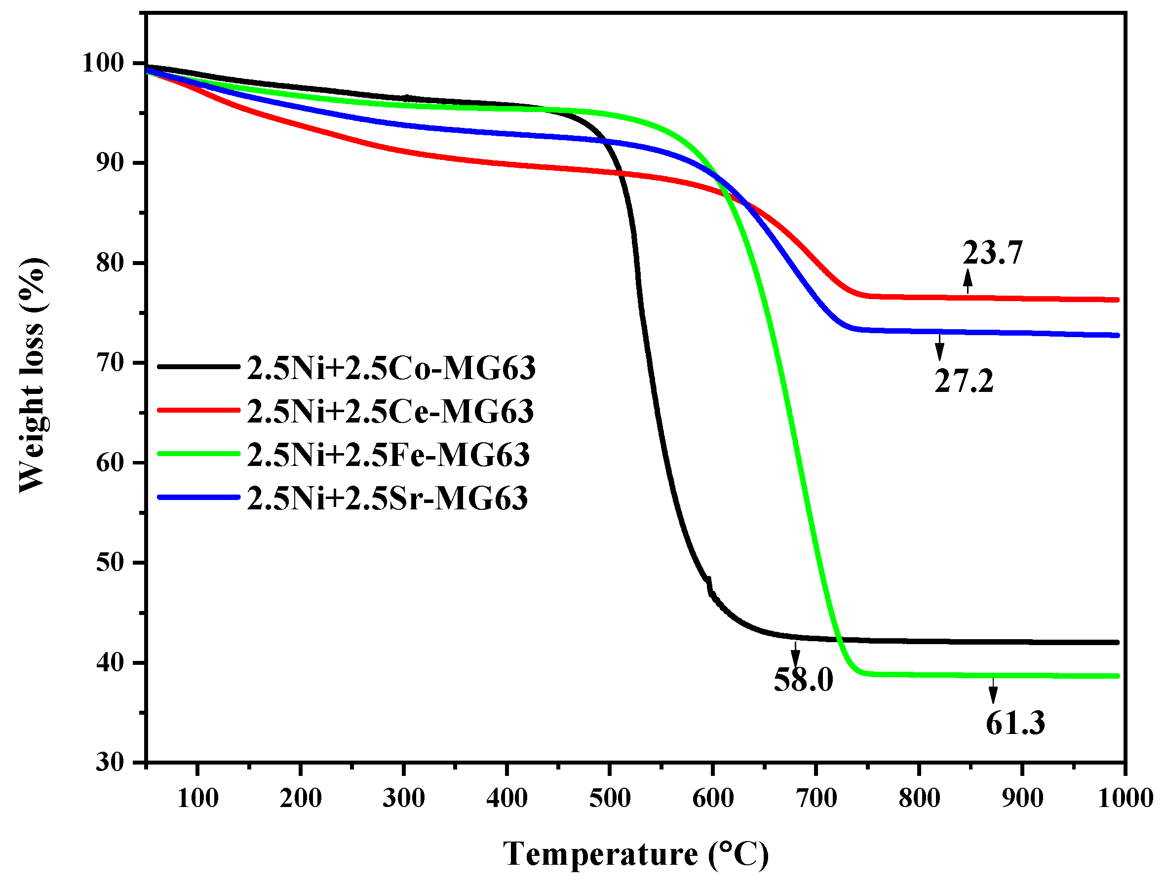
2.8. TGA
3. Materials
3.1. Preparation of Catalysts
3.2. Catalytic Evaluation
3.3. Catalyst Characterization
4. Conclusions
Author Contributions
Funding
Data Availability Statement
Acknowledgments
Conflicts of Interest
References
- Yan, X.; Hu, T.; Liu, P.; Li, S.; Zhao, B.; Zhang, Q.; Jiao, W.; Chen, S.; Wang, P.; Lu, J.; et al. Highly Efficient and Stable Ni/CeO2-SiO2 Catalyst for Dry Reforming of Methane: Effect of Interfacial Structure of Ni/CeO2 on SiO2. Appl. Catal. B Environ. 2019, 246, 221–231. [Google Scholar] [CrossRef]
- Cao, P.; Adegbite, S.; Zhao, H.; Lester, E.; Wu, T. Tuning Dry Reforming of Methane for F-T Syntheses: A Thermodynamic Approach. Appl. Energy 2018, 227, 190–197. [Google Scholar] [CrossRef]
- Usman, M.; Daud, W.M.A.W.; Abbas, H.F. Dry Reforming of Methane: In Fl Uence of Process Parameters—A Review. Renew. Sustain. Energy Rev. 2015, 45, 710–744. [Google Scholar] [CrossRef]
- Amin, R.; Liu, B.; Huang, Z.B.; Zhao, Y.C. Hydrogen and Syn Gas Production via CO2 Dry Reforming of Methane over Mg/La Promoted Co-Ni/MSU-S Catalyst. Int. J. Hydrogen Energy 2016, 41, 807–819. [Google Scholar] [CrossRef]
- Al-Fatesh, A.S.; Atia, H.; Ibrahim, A.A.; Fakeeha, A.H.; Singh, S.K.; Labhsetwar, N.K.; Shaikh, H.; Qasim, S.O. CO2 Reforming of CH4: Effect of Gd as Promoter for Ni Supported over MCM-41 as Catalyst. Renew. Energy 2019, 140, 658–667. [Google Scholar] [CrossRef]
- Furkan, H.B.; Rakibul Hasan, K.M.; Uddin, M.J. Greenhouse Gas Emission, GDP, Tertiary Education, and Rule of Law: A Comparative Study between High-Income and Lower-Middle Income Countries. Heliyon 2023, 9, e16265. [Google Scholar] [CrossRef] [PubMed]
- Hamza Fakeeha, A.; Sadeq Al-Fatesh, A.; Aidid Ibrahim, A.; Elhag Abasaeed, A. CO2 Reforming of CH4 over Ni-Catalyst Supported on Yttria Stabilized Zirconia. J. Saudi Chem. Soc. 2021, 25, 101244. [Google Scholar] [CrossRef]
- Yentekakis, I.V.; Dong, F. Grand Challenges for Catalytic Remediation in Environmental and Energy Applications Toward a Cleaner and Sustainable Future. Front. Environ. Chem. 2020, 1, 1–14. [Google Scholar] [CrossRef]
- Zhang, M.; Liu, J.; Zhang, Y.H.; Wang, L.; Li, J.L.; Hong, J.P. Preparation of Highly Dispersed Silicon Spheres Supported Cobalt-Based Catalysts and Their Catalytic Performance for Fischer-Tropsch Synthesis. J. Fuel Chem. Technol. 2023, 51, 608–615. [Google Scholar] [CrossRef]
- Pratschner, S.; Hammerschmid, M.; Müller, S.; Winter, F. Evaluation of CO2 Sources for Power-to-Liquid Plants Producing Fischer-Tropsch Products. J. CO2 Util. 2023, 72, 102508. [Google Scholar] [CrossRef]
- Aramouni, N.A.K.; Touma, J.G.; Tarboush, B.A.; Zeaiter, J.; Ahmad, M.N. Catalyst Design for Dry Reforming of Methane: Analysis Review. Renew. Sustain. Energy Rev. 2018, 82, 2570–2585. [Google Scholar] [CrossRef]
- Nikoo, M.K.; Amin, N.A.S. Thermodynamic Analysis of Carbon Dioxide Reforming of Methane in View of Solid Carbon Formation. Fuel Process. Technol. 2011, 92, 678–691. [Google Scholar] [CrossRef]
- Al-Zahrani, S.A.; Al-Fatesh, A.S.; Kaydouh, M.N.; Al Otaibi, A.; Francesco, F.; Fakeeha, A.H.; El Hassan, N. High Carbon-Resistant Nickel Supported on Yttria–Zirconia Catalysts for Syngas Production by Dry Reforming of Methane: The Promoting Effect of Cesium. Alexandria Eng. J. 2023, 74, 371–386. [Google Scholar] [CrossRef]
- Abasaeed, A.E.; Al-Fatesh, A.S.; Naeem, M.A.; Ibrahim, A.A.; Fakeeha, A.H. Catalytic Performance of CeO2 and ZrO2 Supported Co Catalysts for Hydrogen Production via Dry Reforming of Methane. Int. J. Hydrogen Energy 2015, 40, 6818–6826. [Google Scholar] [CrossRef]
- Muraleedharan Nair, M.; Kaliaguine, S. Structured Catalysts for Dry Reforming of Methane. New J. Chem. 2016, 40, 4049–4060. [Google Scholar] [CrossRef]
- Abdullah, B.; Abd Ghani, N.A.; Vo, D.V.N. Recent Advances in Dry Reforming of Methane over Ni-Based Catalysts. J. Clean. Prod. 2017, 162, 170–185. [Google Scholar] [CrossRef]
- Palanichamy, K.; Umasankar, S.; Ganesh, S.; Sasirekha, N. Highly Coke Resistant Ni-Co/KCC-1 Catalysts for Dry Reforming of Methane. Int. J. Hydrogen Energy 2023, 48, 11727–11745. [Google Scholar] [CrossRef]
- Almeida, C.M.R.; Ghica, M.E.; Durães, L. An Overview on Alumina-Silica-Based Aerogels. Adv. Colloid Interface Sci. 2020, 282, 102189. [Google Scholar] [CrossRef]
- Wang, S.; Lu, G.Q.M. CO2 Reforming of Methane on Ni Catalysts: Effects of the Support Phase and Preparation Technique. Appl. Catal. B Environ. 1998, 16, 269–277. [Google Scholar] [CrossRef]
- Bian, Z.; Das, S.; Wai, M.H.; Hongmanorom, P.; Kawi, S. A Review on Bimetallic Nickel-Based Catalysts for CO2 Reforming of Methane. ChemPhysChem 2017, 18, 3117–3134. [Google Scholar] [CrossRef]
- Velisoju, V.K.; Virpurwala, Q.J.S.; Attada, Y.; Bai, X.Q.; Davaasuren, B.; Hassine, M.B.; Yao, X.L.; Lezcano, G.; Kulkarni, S.R.; Castano, P. Overcoming the kinetic and deactivation limitations of Ni catalyst by alloying it with Zn for the dry reforming of methane. J. CO2 Util. 2023, 75, 102573. [Google Scholar] [CrossRef]
- Gaillard, M.; Virginie, M.; Khodakov, A.Y. New Molybdenum-Based Catalysts for Dry Reforming of Methane in Presence of Sulfur: A Promising Way for Biogas Valorization. Catal. Today 2017, 289, 143–150. [Google Scholar] [CrossRef]
- De, S.; Zhang, J.; Luque, R.; Yan, N. Ni-Based Bimetallic Heterogeneous Catalysts for Energy and Environmental Applications. Energy Environ. Sci. 2016, 9, 3314–3347. [Google Scholar] [CrossRef]
- Hu, Y.H.; Ruckenstein, E. Comment on “Dry Reforming of Methane by Stable Ni-Mo Nanocatalysts on Single-Crystalline MgO”. Science 2020, 368, 777–781. [Google Scholar] [CrossRef] [PubMed]
- Luisetto, I.; Tuti, S.; Di Bartolomeo, E. Co and Ni Supported on CeO2 as Selective Bimetallic Catalyst for Dry Reforming of Methane. Int. J. Hydrogen Energy 2012, 37, 15992–15999. [Google Scholar] [CrossRef]
- Zhang, T.; Liu, Z.; Zhu, Y.A.; Liu, Z.; Sui, Z.; Zhu, K.; Zhou, X. Dry Reforming of Methane on Ni-Fe-MgO Catalysts: Influence of Fe on Carbon-Resistant Property and Kinetics. Appl. Catal. B Environ. 2020, 264, 118497. [Google Scholar] [CrossRef]
- Theofanidis, S.A.; Galvita, V.V.; Poelman, H.; Marin, G.B. Enhanced Carbon-Resistant Dry Reforming Fe-Ni Catalyst: Role of Fe. ACS Catal. 2015, 5, 3028–3039. [Google Scholar] [CrossRef]
- Papavasiliou, J.; Rawski, M.; Vakros, J.; Avgouropoulos, G. A Novel Post-Synthesis Modification of CuO-CeO2 Catalysts: Effect on Their Activity for Selective CO Oxidation. ChemCatChem 2018, 10, 2096–2106. [Google Scholar] [CrossRef]
- Yang, E.H.; Noh, Y.S.; Ramesh, S.; Lim, S.S.; Moon, D.J. The Effect of Promoters in La0.9M0.1Ni0.5Fe0.5O3 (M = Sr, Ca) Perovskite Catalysts on Dry Reforming of Methane. Fuel Process. Technol. 2015, 134, 404–413. [Google Scholar] [CrossRef]
- Thommes, M.; Kaneko, K.; Neimark, A.V.; Olivier, J.P.; Rodriguez-Reinoso, F.; Rouquerol, J.; Sing, K.S.W. Physisorption of Gases, with Special Reference to the Evaluation of Surface Area and Pore Size Distribution (IUPAC Technical Report). Pure Appl. Chem. 2015, 87, 1051–1069. [Google Scholar] [CrossRef]
- Al-Fatesh, A.S.; Kumar, R.; Kasim, S.O.; Aidid, A.; Anis, I.; Fakeeha, H.; Abasaeed, A.E.; Atia, H.; Armbruster, U.; Kreyenschulte, C.; et al. Effect of Cerium Promoters on an MCM-41-Supported Nickel Catalyst in Dry Reforming of Methane. Cite This Ind. Eng. Chem. Res 2021, 2022, 174. [Google Scholar] [CrossRef]
- Mironova-Ulmane, N.; Kuzmin, A.; Sildos, I.; Puust, L.; Grabis, J. Magnon and Phonon Excitations in Nanosized NiO. Latv. J. Phys. Tech. Sci. 2019, 56, 61–72. [Google Scholar] [CrossRef]
- Shebanova, O.N.; Peter Lazor, P. Raman study of magnetite (Fe3O4): Laser-induced thermal effects and oxidation. J. Raman Spectrosc. 2003, 34, 845–852. [Google Scholar] [CrossRef]
- Tang, C.-W.; Wang, C.-B.; Chien, S.-H. Characterization of cobalt oxides studied by FT-IR, Raman, TPR and TG-MS. Thermochim. Acta 2008, 473, 68–73. [Google Scholar] [CrossRef]
- Cazzanelli, E.; Kuzmin, A.; Mariotto, G.; Mironova-Ulmane, N. Study of Vibrational and Magnetic Excitations in NicMg1-CO Solid Solutions by Raman Spectroscopy. J. Phys. Condens. Matter 2003, 15, 2045–2052. [Google Scholar] [CrossRef]
- Funkenbusch, E.F.; Cornilsen, B.C. Two-Magnon Raman Scattering in Calcium Doped NiO. Solid State Commun. 1981, 40, 707–710. [Google Scholar] [CrossRef]
- González-Castaño, M.; Dorneanu, B.; Arellano-García, H. The Reverse Water Gas Shift Reaction: A Process Systems Engineering Perspective. React. Chem. Eng. 2021, 6, 954–976. [Google Scholar] [CrossRef]
- Stroud, T.; Smith, T.J.; Le Saché, E.; Santos, J.L.; Centeno, M.A.; Arellano-Garcia, H.; Odriozola, J.A.; Reina, T.R. Chemical CO2 Recycling via Dry and Bi Reforming of Methane Using Ni-Sn/Al2O3 and Ni-Sn/CeO2-Al2O3 Catalysts. Appl. Catal. B Environ. 2018, 224, 125–135. [Google Scholar] [CrossRef]
- Zou, Z.; Zhang, T.; Lv, L.; Tang, W.; Zhang, G.; Gupta, R.K.; Wang, Y.; Tang, S. Preparation adjacent Ni-Co bimetallic nano catalyst for dry reforming of methane. Fuel 2023, 343, 128013. [Google Scholar] [CrossRef]
- Palanichamy, K.; Sasirekha, N. Dry reforming of methane using bimetallic Pt–Ni/TiSBA-15: Effect of Si/Ti ratio on catalytic activity and stability. Int. J. Hydrogen Energy 2023, 48, 31126–31141. [Google Scholar] [CrossRef]
- Mohandessi, M.; Tavakolian, M.; Rahimpour, M.R. Cadmium as a robust and novel promoter over Ni@γ-Al2O3 catalysts in dry methane reforming. ACS Appl. Energy Mater. 2023, 6, 8209–8220. [Google Scholar] [CrossRef]
- Yao, L.; Galvez, M.E.; Hu, C.; Da Costa, P. Mo-Promoted Ni/Al2O3 Catalyst for Dry Reforming of Methane. Int. J. Hydrogen Energy 2017, 42, 23500–23507. [Google Scholar] [CrossRef]


| Sample | BET (m2/g) | P.V. (cm3/g) | Pore Size (Å) |
|---|---|---|---|
| 2.5Ni+2.5Co-MG63 | 199 | 0.309 | 58.7 |
| 2.5Ni+2.5Ce-MG63 | 201 | 0.312 | 56.7 |
| 2.5Ni+2.5Fe-MG63 | 200 | 0.329 | 59.8 |
| 2.5Ni+2.5Sr-MG63 | 174 | 0.283 | 58.2 |
| Sample | Maximum Temperature (°C) | Quantity (cm3/g.STP) | Total Quantity (cm3/g.STP) |
|---|---|---|---|
| 2.5Ni+2.5Co-MG63 | 343.4 923.6 | 0.36 19.18 | 19.55 |
| 2.5Ni+2.5Ce-MG63 | 684.2 944.7 | 0.34 12.13 | 12.47 |
| 2.5Ni+2.5Fe-MG63 | 543.2 924.3 | 17.46 14.22 | 31.68 |
| 2.5Ni+2.5Sr-MG63 | 636.4 705.8 957.9 | 0.10 1.24 13.12 | 14.57 |
| Sample | Temperature (°C) | Quantity (cm3/g.STP) | Total Quantity (cm3/g.STP) |
|---|---|---|---|
| 2.5Ni+2.5Co-MG63 | 251.2 696.5 | 10.04 0.39 | 10.43 |
| 2.5Ni+2.5Ce-MG63 | 252.8 729.1 | 9.66 0.36 | 10.02 |
| 2.5Ni+2.5Fe-MG63 | 273. 6 | 28.38 | 28.38 |
| 2.5Ni+2.5Sr-MG63 | 271.0 831.6 | 28.32 0.50 | 28.82 |
| Cat-Name (°C) | CH4/CO2 | GHSV (mL/hgcat) | RT (°C) | CH4-Conv. (%) | CO2-Conv. (%) | REF. |
|---|---|---|---|---|---|---|
| Ni-Mn/CeO2-ZrO2 | 1:1 | 20,000 | 600 | 39 | 40 | [34] |
| Na-Ni/ZrO2 | 68:31 | 12,000 | 675 | 25 | 55 | [37] |
| Ni-Cu/Mg(Al)O | 1:1 | 60,000 | 600 | 50 | 57 | [38] |
| Ni-Co/SiO2 | 1:1 | 700 | 24,000 | 30 | 40 | [39] |
| Ni-Pt/Ti-SBA-15 | 1:1 | 700 | 36,000 | 57 | 60 | [40] |
| Ni-Cd | 1:1 | 700 | 12,000 | 50 | 60 | [41] |
| Ni-Mo/Al2O3 | 1:1 | 20,000 | 900 | 60 | 70 | [42] |
| 2.5Ni+2.5Co-MG63 | 25:25 | 36,000 | 700 | 72 | 76 | This work |
Disclaimer/Publisher’s Note: The statements, opinions and data contained in all publications are solely those of the individual author(s) and contributor(s) and not of MDPI and/or the editor(s). MDPI and/or the editor(s) disclaim responsibility for any injury to people or property resulting from any ideas, methods, instructions or products referred to in the content. |
© 2023 by the authors. Licensee MDPI, Basel, Switzerland. This article is an open access article distributed under the terms and conditions of the Creative Commons Attribution (CC BY) license (https://creativecommons.org/licenses/by/4.0/).
Share and Cite
Ibrahim, A.A.; Fakeeha, A.H.; Abasaeed, A.E.; Wazeer, I.; Bentalib, A.; Siva Kumar, N.; Abu-Dahrieh, J.K.; Al-Fatesh, A.S. The Effectiveness of Ni-Based Bimetallic Catalysts Supported by MgO-Modified Alumina in Dry Methane Reforming. Catalysts 2023, 13, 1420. https://doi.org/10.3390/catal13111420
Ibrahim AA, Fakeeha AH, Abasaeed AE, Wazeer I, Bentalib A, Siva Kumar N, Abu-Dahrieh JK, Al-Fatesh AS. The Effectiveness of Ni-Based Bimetallic Catalysts Supported by MgO-Modified Alumina in Dry Methane Reforming. Catalysts. 2023; 13(11):1420. https://doi.org/10.3390/catal13111420
Chicago/Turabian StyleIbrahim, Ahmed A., Anis H. Fakeeha, Ahmed E. Abasaeed, Irfan Wazeer, Abdulaziz Bentalib, Nadavala Siva Kumar, Jehad K. Abu-Dahrieh, and Ahmed S. Al-Fatesh. 2023. "The Effectiveness of Ni-Based Bimetallic Catalysts Supported by MgO-Modified Alumina in Dry Methane Reforming" Catalysts 13, no. 11: 1420. https://doi.org/10.3390/catal13111420