Article

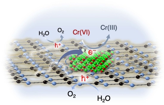
Ni2P-Modified P-Doped Graphitic Carbon Nitride Hetero-Nanostructures for Efficient Photocatalytic Aqueous Cr(VI) Reduction

by
Evangelos K. Andreou
,
Eirini D. Koutsouroubi
,
Ioannis Vamvasakis
and
Gerasimos S. Armatas
*
Department of Materials Science and Technology, University of Crete, 70013 Heraklion, Greece
*
Author to whom correspondence should be addressed.
Catalysts 2023, 13(2), 437; https://doi.org/10.3390/catal13020437
Submission received: 30 January 2023 / Revised: 12 February 2023 / Accepted: 13 February 2023 / Published: 17 February 2023
(This article belongs to the Special Issue Feature Papers in Environmental Catalysis)

Abstract

:
Targeting heterostructures with modulated electronic structures and efficient charge carrier separation and mobility is an effective strategy to improve photocatalytic performance. In this study, we report the synthesis of 2D/3D hybrid heterostructures comprising P-doped graphitic carbon nitride (g-C3N4) nanosheets (ca. 50–60 nm in lateral size) and small-sized Ni2P nanoparticles (ca. 10–12 nm in diameter) and demonstrate their prominent activity in the photocatalytic reduction of Cr(VI). Utilizing a combination of spectroscopic and electrochemical characterization techniques, we unveil the reasons behind the distinct photochemical performance of these materials. We show that Ni2P modification and P doping of the g-C3N4 effectively improve the charge-carrier transportation and spatial separation through the interface of Ni2P/P-doped g-C3N4 junctions. As a result, the catalyst containing 15 wt.% Ni2P exhibits superior photocatalytic activity in the detoxification of Cr(VI)-contaminated effluents under UV-visible light illumination, presenting an apparent quantum yield (QY) of 12.5% at 410 nm, notably without the use of sacrificial additives. This study marks a forward step in understanding and fabricating cost-effective photocatalysts for photochemical applications.

Graphical Abstract

1. Introduction

Water pollution poses a major threat not only to aquatic ecosystems but to human lifespans as well [1,2]. Quality of life has been tremendously improved through the rapid industrialization that took place to meet our commercialized needs. This extensive use of the industrial sector has a major impact on the environment and especially on the pollution of aquatic habitats. Some of the most severe chemical wastes are toxic metals, such as Pb, Hg, As and Cr [3]. In the case of chromium pollution, Cr metal ions can be predominantly found in two different oxidation states, the trivalent (Cr(III)) and hexavalent (Cr(VI)) forms. While Cr(III) compounds are not considered highly life-threatening agents, the Cr(VI) oxo-species are very harmful in the cases of ingestion through potable water [4,5,6]. Due to the extremely high toxicity and solubility of Cr(VI) in aquatic solutions, Cr(VI) has been categorized as a Group 1 carcinogen to humans with an LD50 of 50–150 mg·Kg−1 by the International Agency for Research on Cancer [7]. Various techniques have been applied for the remediation of Cr(VI)-polluted solutions, such as chemical precipitation, membrane filtration, adsorption, ion exchange, etc. [8,9,10,11]. Although the above techniques can be quite effective, their large-scale deployment in decontamination of Cr(VI)-polluted wastewaters is limited by high operation costs; they require excessive amounts of adsorbents or reducing reagents, such as SO2 and FeSO4. Alternately, the cost-effectiveness and scalable implementation of the photochemical conversion of Cr(VI) to Cr(III) makes this method one of the most sustainable solutions for environmental pollution [12,13,14]. Sunlight irradiation is the cheapest and cleanest energy source that can be utilized for chemical conversion. Also, thanks to the undemanding isolation process, the photocatalysts can be operated on freely until the full Cr(VI) reduction to Cr(III), and then they can be isolated and reused successfully in repeated catalytic cycles. An additional advantage of the photocatalytic method is that, except for heavy metals, there is a plethora of organic pollutants in industrial effluents, such as phenol, amines, dyes, ethylenediaminetetraacetic acid (EDTA), etc., which may act as sacrificial agents, accelerating the reaction rate of Cr(VI) reduction [15,16]. Those organic pollutants, which serve as electron donors during the photocatalytic process, can be degraded into their oxidized forms that are less toxic and, in some cases, can be further isolated. It is clear that photocatalytic Cr(VI) reduction is a low-cost and environmentally friendly technique, which not only can be used to decontaminate aquatic environments from toxic metals but can also simultaneously degrade organic pollutants with high reaction kinetics and efficiency.
Graphitic carbon nitride (g-C3N4) is a well-known 2D semiconductor material, which, due to its high chemical and thermal stability along with its unique electronic properties, presents interesting perspectives in various applications and especially in the field of photocatalysis [17,18,19]. This organic semiconductor has recently attracted the attention of the research community, since it is a non-toxic material and its synthesis requires the use of inexpensive raw materials, such as urea, thiourea and melamine. Also, high-purity g-C3N4 can be easily produced at a large scale for industrial use. Although g-C3N4 can be considered an ideal candidate for heterogeneous photocatalysis, it suffers from instantaneous electron-hole recombination, limited utilization of solar radiation (it has a band gap (Eg) of 2.7–2.8 eV) and low density of surface-active sites. These flaws guided the materials research in the direction of devising heterostructures with metals (Ag, Au, Pd, Ru, etc.) and metal oxide or chalcogenide semiconductors, doping the structure with metal (Fe, Ni, Co, Mn, La, etc.) or non-metal (B, F, O, P, S, etc.) ions and other synthetic modifications in order to further assist the photocatalytic activity of this low-cost semiconductor [20,21,22,23]. Compared to the other optimization approaches, the construction of heterojunctions between g-C3N4 and another material (co-catalyst) seems to be a very effective way of enhancing the photocatalytic performance of g-C3N4 [24,25,26]. Specifically, the close contact between the two components plays a crucial role in the electronic interfacial interactions, promoting the efficient transfer and separation of photogenerated electrons and holes at the interface, thereby improving photocatalytic efficiency. Also, the utilization of solar energy by g-C3N4 can be significantly improved by the proper employment of visible light-responsive co-catalysts. To this end, a diverse set of semiconductor materials, like BiVO4, SnS2, CdS and MoS2, have been used for the formation of heterojunctions with g-C3N4 for photocatalytic reactions [27,28,29,30]. Although these co-catalysts improve interfacial charge separation and transportation, certain pitfalls in this research are the low electron transfer kinetics and poor photochemical stability. Propitious replacements of the conventional semiconductors (metal oxides, sulfides, etc.) are the transition metal phosphides (TMPs), such as Ni2P, CoP, Cu3P, MoP, etc. [31,32,33,34]. Despite the small progress, TMPs have already emerged with great potential in overcoming the main flaws of conventional semiconductors, demonstrating excellent multiple redox activity, enhanced visible light absorption and outstanding stability in both acidic and alkaline media [35]. Moreover, TMPs are non-toxic and inexpensive materials. Taking into consideration the above premises, the coupling of g-C3N4 with TMPs to form heterojunctions can provide sustainable photocatalysts with combined high efficiency and long-term stability.
In this article, we report for the first time on the synthesis of Ni2P-modified P-doped g-C3N4 heterostructures via a facile two-step thermal polycondensation and hydrothermal method and demonstrate their eminence in photocatalytic detoxification of aqueous Cr(VI) solutions under UV-visible light irradiation. The resulting Ni2P/P-g-C3N4 materials comprise P-doped g-C3N4 nanolayers and small-size Ni2P nanoparticles. By using a combination of electrochemical and spectroscopic techniques, we provide a mechanistic understanding of charge transport and photochemical reactions in this catalytic system. Our findings indicate that Ni2P/P-g-C3N4 hetero-nanostructures allow the generation of electron transfer channels with improved charge carrier dissociation across the junction, leading to superior photocatalytic performance. As a result, the catalyst with 15 wt.% Ni2P content attains complete reduction of Cr(VI) to Cr(III) in 80 min, reaching a photon to chemical conversion yield of 12.5% at 410 nm monochromatic light, importantly, without the aid of sacrificial agents. Moreover, Ni2P/P-g-C3N4 catalysts show a persistently high photochemical activity towards Cr(VI) reduction (>99% Cr(VI) reduction in 80 min) even with the coexistence of other competing ions. The results of this study demonstrate the prospective applicability of the Ni2P-modified P-doped g-C3N4 hetero-nanostructures for environmental protection, including detoxification of industrial effluents with rich Cr(VI) concentration.

2. Results and Discussion

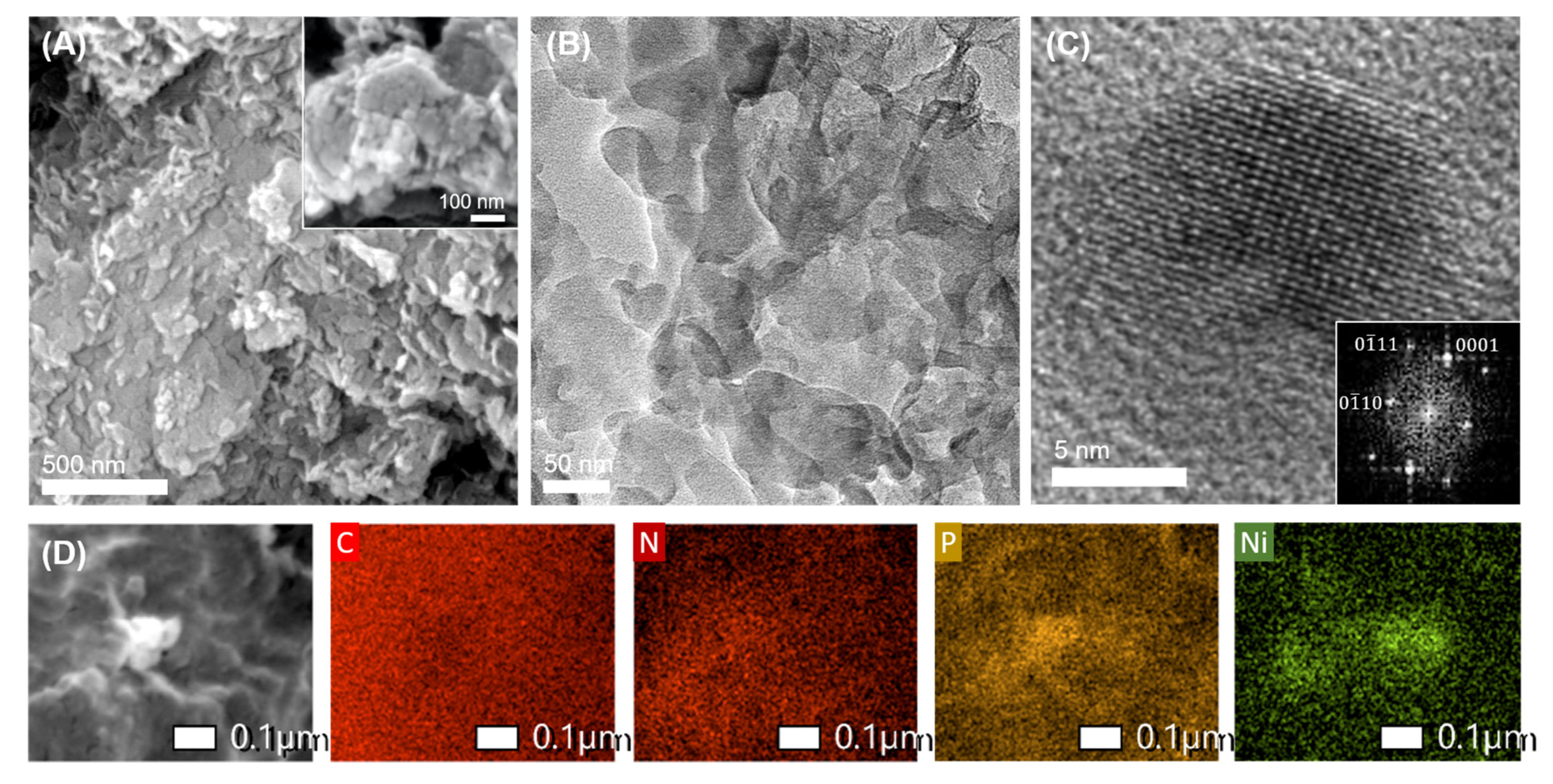
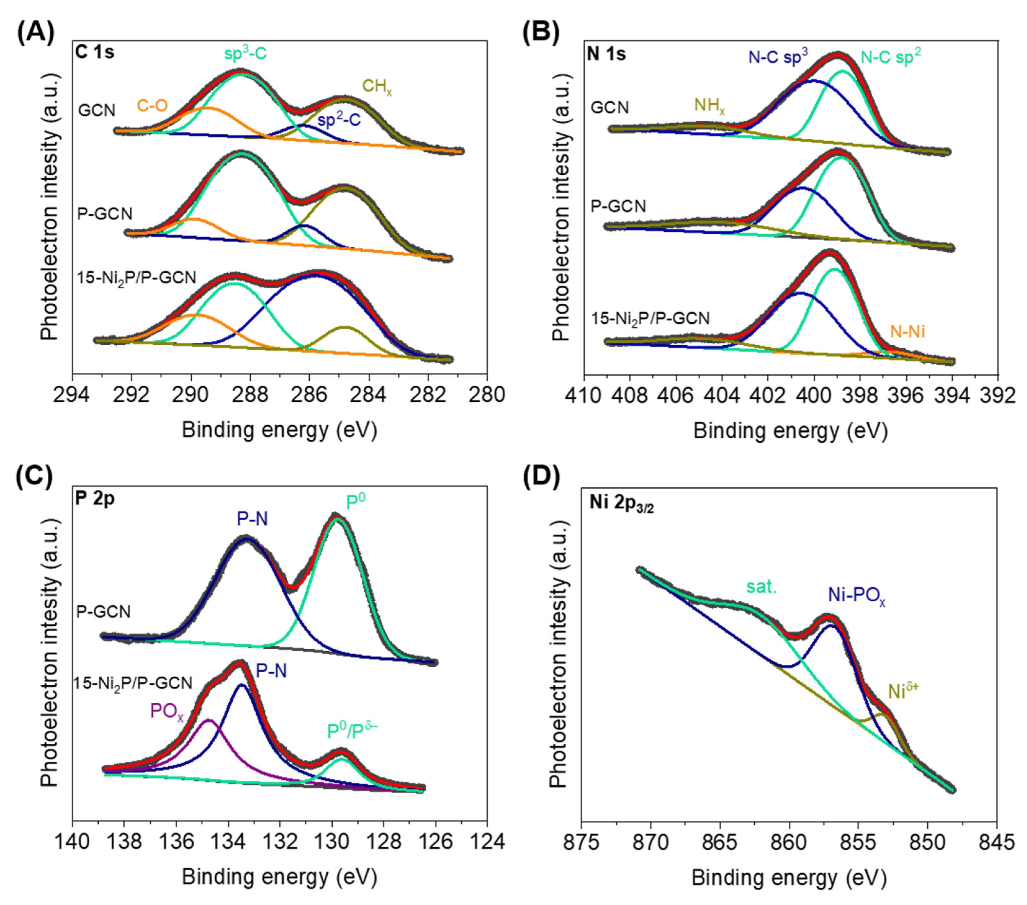
2.1. Synthesis and Structural Characterization

The Ni2P-modified P-doped g-C3N4 nanosheets were synthesized via a facile two-step synthetic procedure, as described in Figure 1A. Namely, we used a conventional thermal polycondensation reaction of urea to prepare g-C3N4 (denoted as GCN_b). Next, the growth of Ni2P nanoparticles on g-C3N4 and chemical doping of the host polymer with phosphorus atoms was achieved by reacting the as-made g-C3N4 with NiCl2 and red P precursors under hydrothermal conditions, so that 2D/3D hybrid hetero-nanostructures of tightly connected P-doped g-C3N4 nanosheets and Ni2P nanoparticles were obtained. In this hydrothermal process, P reacts with Ni2+ ions on the surface of g-C3N4 to give Ni2P nanoparticles, while also substitutionally doping the g-C3N4 crystal lattice. By regulating the concentrations of NiCl2 and red P in the reaction mixture, a series of Ni2P/P-g-C3N4 heterostructures (denoted as x-Ni2P/P-GCN) were produced with different weight contents of Ni2P, i.e., x = 5, 10, 15 and 20 wt.%. For comparison reasons, pure Ni2P and undoped (denoted as GCN) and P-doped (denoted as P-GCN) g-C3N4 nanosheets were also prepared using a similar hydrothermal process and thoroughly studied.
The crystal structure and chemical composition of as-prepared catalysts were assessed using energy-dispersive X-ray spectroscopy (EDS) and powder X-ray diffraction (XRD). The EDS spectra verified the presence of Ni, P, C and N elements in the Ni2P-modified samples. On the basis of the EDS atomic ratio of Ni:N, the Ni2P contents in these materials were found to be very close to the expected compositions by the stoichiometry of reactions, see Table S1. Results of XRD experiments on pure Ni2P, pristine GCN and Ni2P/P-GCN samples are shown in Figure 1B. The XRD patterns of Ni2P/P-GCN display two diffraction peaks at ~13.2° and ~27.8°, corresponding to the (100) and (002) crystal planes of g-C3N4 (JCPDS card no. 87-1526), and several distinct diffraction peaks in the 2θ range of 40–60°, corresponding to the crystal planes of hexagonal Ni2P (JCPDS card no. 74-1385). Using Scherrer’s equation, the broadening of the (111) diffraction peak of Ni2P particles coincided with the formation of crystallites with a 15–20 nm grain size, which is consistent with the Ni2P particle diameter obtained from TEM data (see below). These results suggest that Ni2P nanoparticles are eventually formed on the surface of g-C3N4 through the employed hydrothermal reaction. By comparing the XRD patterns of GCN and P-GCN, we found that doping the structure of g-C3N4 with phosphorus does not alter the crystal symmetry; both GCN and P-GCN samples show similar XRD profiles (Figure S1).
The morphology of the 15 wt.% Ni2P-modified P-doped g-C3N4 (15-Ni2P/P-GCN), which is the best catalyst in this study, was observed by field emission scanning electron microscopy (FE-SEM) and transmission electron microscopy (TEM). Representative FE-SEM images in Figure 2A reveal that this sample has a flake-like morphology in which plenty of intersecting nanosheets form a layered network structure. In line with this, a low magnification TEM image of 15-Ni2P/P-GCN, shown in Figure 2B, further confirms a nanoflake-assembled morphology of randomly interconnected nanosheets with a lateral dimension of approximately 50–60 nm. Compared to as-made g-C3N4 (GCN_b), the lateral size of C3N4 flakes of hydrothermal-treated materials is much smaller; GCN_b consists of multi-layer flakes with a lateral size of around 0.8–1.2 μm, as evidenced by FE-SEM (see Figure S2). Figure 2C is a high-resolution TEM (HRTEM) image of 15-Ni2P/P-GCN, which shows an isolated Ni2P nanoparticle with a diameter of 10–12 nm (appearing as dark, small areas) studded on the surface of g-C3N4 (appearing as light areas), in line with the EDS mapping results shown below. The very similar dimension obtained from TEM particle size and XRD grain size implies a single-crystalline nature of Ni2P particles. The hexagonal lattice structure of Ni2P was further verified by fast Fourier transform (FFT) analysis of the TEM image. The FFT pattern obtained from this particle reasonably correlates to the crystal planes along the [100] zone axis of the hexagonal Ni2P (space group: P-62m) (inset of Figure 2C). In Figure 2D, the SEM-EDS elemental mapping indicates a uniform distribution of the C, N and P atoms within the detection area of the 15-Ni2P/P-GCN surface, while Ni atoms distributed at certain regions, possibly at the edges of the g-C3N4 sheets [36]. Taken together, these results affirm the successful growth of Ni2P nanoparticles on the surface of the P-doped g-C3N4 nanosheets, resulting in the formation of Ni2P/P-doped g-C3N4 heterojunctions with, importantly, intimate contact. The strong integration between Ni2P and P-doped g-C3N4 components is advantageous for photocatalysis since it allows for the smooth transfer and dissociation of charges across the Ni2P/P-g-C3N4 interface.
The valence state of elements in the as-prepared materials was analyzed by X-ray photoelectron spectroscopy (XPS). Figure 3A shows the C 1s spectra for GCN, P-GCN and 15-Ni2P/P-GCN, which is the most active catalyst in this series. For the GCN, deconvolution of the C 1s signal yields four singlet peaks at 284.8, 286.2, 288.3, 289.5 ± 0.2 eV binding energy due to the adventitious carbon, sp2-bonded (N–C=N) and sp3-bonded (C–N) carbons in triazine units, and surface COx impurities of g-C3N4, respectively [37,38]. Similar to this, the C 1s peaks associated with the N–C=N and C–N linkages and COx impurities of P-GCN appear at 286.2, 288.3 and 289.9 ± 0.2 eV and those peaks for 15-Ni2P/P-GCN appear at 285.9, 288.5 and 289.8 ± 0.2 eV, respectively. The weak C 1s signal at higher binding energy indicates minor surface oxidation, possibly due to the synthesis procedure and air exposure of the samples. In the deconvoluted N 1s spectra (Figure 3B), the prominent peaks at 398.8 and 400.0 ± 0.2 eV and the broad feature at 404.6 ± 0.2 eV for GCN (398.8, 400.5 and 404.1 ± 0.2 eV for P-GCN) are assigned to the sp2-bonded (pyridinic N) and sp3-bonded (pyrrolic N) nitrogen and terminal-NHx species of g-C3N4, respectively [39]. For the 15-Ni2P/P-GCN catalyst, the N 1s XPS spectrum indicates similar chemical states at 399.1 and 400.6 and 404.7 ± 0.2 eV, while the newly appeared photoelectron peak at 396.8 ± 0.2 eV can be attributed to the metal (Ni) −N bond [40], indicating tight interfacial adhesion by covalent bonding between Ni2P particles and the host polymer matrix. Figure 3C displays P 2p XPS spectra for P-GCN and 15-Ni2P/P-GCN. The P 2p signal of P-GCN manifests as two singlet peaks at 129.8 and 133.2 ± 0.3 eV, in agreement with the literature data for P–P and P–N bonds, respectively [41]. This confirms the incorporation of P atoms into the g-C3N4 lattice during the hydrothermal synthesis, although a small amount of unreactive phosphorus is situated on the surface of the sample. In line with this, the P-GCN possesses a lower C/N atomic ratio than the pristine GCN, that is 0.72 versus 0.73, implying a carbon-deficient g-C3N4 structure, in which we assume C atoms are replaced by P atoms. The deviation of the C/N ratio from the ideal value (C:N = 0.75) for the GCN is likely due to the fracture of some C–N bonds in the triazine rings and, thus, the fragmentation of the g-C3N4 flakes during the hydrothermal process, in accordance with the TEM observations. Similar multiple valence states of P were also observed in the Ni2P-modified sample. Specifically, the P 2p signal of 15-Ni2P/P-GCN consists of three singlet peaks at 129.6, 133.5 and 134.7 ± 0.3 eV, which are assigned to the P–P and/or Ni–P coordination bonds as well as the P–N linkages and POx impurities due to the inadequate surface oxidation of P-doped GCN, respectively [42,43,44,45]. According to the XPS results, the P-doping content in the implanted samples is roughly 0.3 at.%. As for the Ni 2p3/2 spectrum of 15-Ni2P/P-GCN (Figure 3D), the photoelectron peak at 853.0 ± 0.2 eV points to the formation of the Ni–P coordination bonds, while the peak at 856.7 ± 0.2 eV together with the satellite signal at 862.0 ± 0.2 eV imply the presence of the paramagnetic Ni(II) ions owing to the partially oxidized Ni–POx/OH species [40,45,46,47]. Taking together, the results from the above studies unambiguously manifest the successful growth of Ni2P nanoparticles and simultaneously doping of g-C3N4 lattice with phosphorus, highlighting the present synthetic method toward the fabrication of Ni2P/P-doped g-C3N4 hetero-nanostructures with strong interfacial adhesion.
The porosity of the title materials was examined with nitrogen physisorption measurements. Figure S3 depicts the N2 adsorption and desorption isotherms at −196 °C of the GCN_b, GCN, P-GCN and Ni2P/P-GCN samples. All the isotherms showed type-IV curves with a H3-type hysteresis loop, being characteristic of mesoporous systems with slit-shaped pores. Compared with the pristine GCN_b (83 m2·g−1, 0.12 cm3·g−1), GCN and P-GCN exhibit higher Brunauer-Emmett-Teller (BET) surface areas (113 and 97 m2·g−1, respectively) and pore volumes (0.18 and 0.20 cm3·g−1, respectively). The slightly larger porosity of the g-C3N4 samples obtained after hydrothermal treatment can be attributed to the smaller size of C3N4 layers that are randomly stacked together, forming an increased number of interstitial voids. The surface area and pore volume of the Ni2P-modified catalysts were estimated to be 68–92 m2·g−1 and 0.12–0.15 cm3·g−1, respectively, which are slightly lower than the values of GCN and P-GCN due the incorporation of Ni2P particles. Using the non-local density functional theory (NLDFT) analysis with slit pore geometry, the pore width in these materials was found to be ca. 3–3.3 nm (insets of the Figure S3). All the textural properties of the as-prepared materials are summarized in Table S2.
Ultraviolet-visible/near-IR (UV-vis/NIR) diffuse reflectance spectroscopy was performed to assess the optical properties of the prepared materials. As shown in Figure S4, the treated GCN exhibits an absorption onset at 2.81 eV, which corresponds to the band-to-band electronic transition of g-C3N4. Compared with the bulk GCN_b (it has a band gap of 2.75 eV), GCN shows a remarkable blue shift in energy gap by 60 meV, which is due to the small lateral size of the g-C3N4 layers, which are ca. 50–60 nm according to TEM results (Figure 2B). Meanwhile, doping the structure of g-C3N4 with P leads to a remarkable red shift of the optical absorption; on the basis of the UV-Vis/NIR spectrum, the energy band gap of P-GCN was estimated to be 2.76 eV, see Figure S4. Enriching the crystal lattice of g-C3N4 with P atoms has an immediate effect on the electronic band structure of the material due to the introduction of mid-gap electronic states near the conduction band (CB) edge. A similar effect has been previously observed in other P-doped g-C3N4 materials [48,49]. The Ni2P-modified catalysts show a noteworthy red shift of the absorption spectrum and their band gap energy falls in the range of 2.70–2.74 eV. This remarkable red shift is attributed to the strong electronic interactions and charge transfer phenomena taking place between the tightly connected Ni2P nanoparticles and P-doped g-C3N4 nanosheets in line with electron microscopy and XPS studies. Moreover, the Ni2P/P-GCN catalysts exhibit an apparent absorption band below 2.7 eV (>460 nm) due to the optical absorption response of Ni2P. The Ni2P shows an intense absorption within the entire UV-vis/NIR region (see Figure S5), implying metallic behavior consistent with the literature data [46,50].

2.2. Photocatalytic Reduction of Cr(VI)

The photocatalytic activity of the Ni2P/P-GCN heterostructures was evaluated in the UV-visible (λ > 360 nm) light reduction of Cr(VI) aqueous solution (50 mg·L−1) without any additional hole scavenger. For comparison, we also studied the photocatalytic activity of the pristine (GCN) and P-doped (P-GCN) g-C3N4 samples under the same reaction conditions. The catalytic results shown in Figure 4A reveal that the deposition of Ni2P has a notable impact on the photoactivity of g-C3N4, verifying that Ni2P nanoparticles act as effective co-catalysts in the present catalytic system. Specifically, the conversion of Cr(VI) was complete (>99%) in 80 min with a 15-Ni2P/P-GCN catalyst, whereas it took 3 h for ~44% and ~41% Cr(VI) conversion over GCN and P-GCN, respectively. The other Ni2P-modified catalysts presented lower to moderate catalytic activity in the reduction of Cr(VI) than 15-Ni2P/P-GCN, but still higher than those of GCN and P-GCN materials. Blank experiments revealed no obvious conversion of Cr(VI) in the absence of light or catalyst, confirming that Cr(VI) transformation is a photocatalytic process (Figure 4A). Also, when Ni2P particles were used as a catalyst, no Cr(VI) conversion was detected under the present conditions (results not shown). The high reactivity of Ni2P/P-GCN can be attributed to the improved charge-carrier transportation and spatial separation through the Ni2P/P-doped g-C3N4 junctions due to the tight contact between Ni2P and g-C3N4 components, as evidenced from electron microscopy and XPS results. To rule out this possibility, we also produced a reference catalyst by wet chemical deposition of 15 wt.% Ni2P particles on the surface of g-C3N4 (denoted as 15-Ni2P/GCN_b, see Materials and Methods for details), and we evaluated its photocatalytic activity under similar conditions. This catalyst exhibits very similar Ni2P content, crystal structure, porosity and optical absorption abilities to those of 15-Ni2P/GCN, as evidenced by EDS, XRD, N2 physisorption and UV-vis/NIR spectroscopy measurements (see Table S1 and Figures S4, S6 and S7). Interestingly, 15-Ni2P/GCN_b yielded inferior performance to 15-Ni2P/P-GCN, even lower than that of pristine GCN and P-GCN, giving a respective ~15% Cr(VI) conversion in 3 h. The above results thus indicate that the P-doping and strong adhesion of Ni2P particles to g-C3N4 have a positive effect on the Cr(VI) photoreduction performance of the resulting materials. Consequently, we focused our further catalytic studies on reactions with a 15-Ni2P/P-GCN catalyst.
Next, we varied the catalyst loading and the solution pH to optimize the reaction conditions. Figure S8 compares the photocatalytic reduction of Cr(VI) caused by different mass loadings of 15-Ni2P/P-GCN, i.e., from 0.4 to 1 g·L−1. It can be seen that the Cr(VI) reduction efficiency increases with the catalyst concentration and reaches a maximum of 0.8 g·L−1. As for the slightly inferior photoactivity at 1 g·L−1 load of catalyst, it could be associated with the increased light scattering by the particle suspension. Besides catalyst concentration, the solution acidity has a prominent effect on the Cr(VI) photoreduction process. As shown in Figure S9, the 15-Ni2P/P-GCN catalyst shows a significantly increased Cr(VI) reduction activity as the solution pH changes from 6 to 1 (keeping the catalyst load constant at 0.8 g·L−1). Of particular note, in pH 1 solution, 15-Ni2P/P-GCN eliminates >99% of Cr(VI) (50 mg·L−1) in only 50 min. We interpret this behavior as the propitious adsorption of Cr(VI) oxo species (predominantly existent in the HCrO4 form at pH < 4) on the catalyst surface; g-C3N4 has a point of zero charge ~4–5 and, thus, at low pH environment its surface is positively charged. Also, in an acidic solution, the excessive concentration of hydronium ions (H3O+) has an accelerating action on the reduction process of Cr(VI), as shown by the overall reaction in Equation (1).
2HCrO4(aq) + 8H+(aq) → 2Cr3+(aq) + 3/2O2(g) + 5H2O(l)
Under optimal reaction conditions (0.8 g·L−1 catalyst load), the photoreduction rate of Cr(VI) over 15-Ni2P/P-GCN reaches 15.9 μmol·h−1 at pH 2 under UV-visible (λ > 360 nm) light irradiation. Also, the apparent quantum yield (QY) of this process is calculated to be as high as 12.5 % at 410 ± 10 nm, assuming full absorption of the incident light by the catalyst. The activity of 15-Ni2P/P-GCN is comparable and even superior to that of some of the state-of-the-art g-C3N4-based catalysts for Cr(VI) reduction, even if operating with electron donor additives (see Table S3).
The practical applicability of the Ni2P/P-GCN catalytic system can be seen in the decontamination of wastewater containing Cr(VI) along with large amounts of various competitive ions. This study was conducted using the same load of 15-Ni2P/P-GCN catalyst (0.8 g·L−1) in Cr(VI) aqueous solution (50·mg·L−1) without and in the presence of SO42−, CO32−, NO3, Cl, Na+, Cu2+, Mn2+ and Zn2+ ions (50·mg·L−1 for each ion), which is a typical composition of industrial effluents [51,52]. Commonly, the presence of interfering ions (such as SO42−, NO3, Cl, Mn2+ and Zn2+) deteriorates the Cr(VI) reduction ability of the catalyst due to the competitive adsorption effects and redox reactions at the catalyst surface [53,54]. Results from Figure 4B show that 15-Ni2P/P-GCN still demonstrates a high Cr(VI) photoreduction activity (>98% Cr(VI) reduction in 80 min), even under the presence of excessive amounts of competing ions in the solution. In addition, the photo-oxidation kinetics of 15-Ni2P/P-GCN were also studied in the presence of EDTA, citric acid and phenol as common organic pollutants of wastewaters, which can serve as sacrificial electron donors. Since electron injection from these organic molecules can overcome the rate limitations of the water oxidation reaction (H2O oxidation proceeds through a four-electron transfer pathway involving various sluggish absorption/dissociation steps), the overall photocatalytic reaction is expected to occur at a faster rate. Figure 4C shows that the reduction reaction of Cr(VI) occurs at a remarkably faster rate when three equivalents of the above pollutants were added to the solution, yielding >99% Cr(VI) conversion in only 5–30 min. These findings explicitly demonstrate that organic pollutants, such as EDTA, citric acid and phenol, may have a positive effect on the photoreduction kinetics of Cr(VI).
The 15-Ni2P/P-GCN also demonstrated very good stability and reusability after multiple cycles of Cr(VI) reduction. The stability of the catalyst was examined by performing three consecutive 80 min photocatalytic tests. Before the catalytic test, the catalyst was separated from the reaction mixture through centrifugation, washed with DI water and added to a fresh Cr(VI) solution. The recycling study showed that 15-Ni2P/P-GCN can be reused for at least three successive catalytic runs without a significant decrease of its activity, maintaining a Cr(VI) conversion efficiency as high as >98% after catalytic tests (Figure 4D). Moreover, EDS and XRD measurements revealed no obvious changes in the chemical composition and crystal structure of the reused 15-Ni2P/P-GCN catalyst, indicating high durability (see Table S1 and Figure S10).

2.3. Effect of Ni2P on the Photocatalytic Activity

To better understand the role of Ni2P on the photocatalytic performance of Ni2P/P-GCN, we performed electrochemical measurements. First, Mott-Schottky (M-S) analysis was used to assess the electronic band structure of the prepared materials (drop-casted on FTO substrates), and the respective M-S plots (1/Csc2 vs. applied potential curves) are depicted in Figure 5A. It can be seen that all the examined catalysts exhibit positive slopes, suggesting n-type conductivity. By extrapolating the linear fits of the M-S slopes to 1/Csc2 = 0, the flat-band (EFB) potentials of the samples were estimated and the obtained results are listed in Table 1. All electrochemical potentials are given relative to the reversible hydrogen electrode (RHE) at pH 7. Considering that EFB is a good proxy value of the conduction band (CB) minimum for n-type doped semiconductors (usually EFB is 0.1–0.3 V more positive than the CB edge) [55], the valence band (VB) potential (EVB), and thus a reasonable band-edge diagram, were obtained for each catalyst by adding the EFB to the respective energy band gap (as estimated from the UV-vis/NIR absorption measurements). As shown in Table 1 and Figure 5B, the EFB position of GCN is located at −1.28 V, which is cathodically shifted by ~60 meV relative to the bulk GCN_b (−1.22 V). Notably, this negative shift in EFB of GCN correlates well with its band gap widening after hydrothermal treatment, which is associated with the confined environment in the nanometer-sized g-C3N4 layers. In addition, the charge donor density (ND) of GCN (3.17 × 1018 cm−3), calculated from the magnitude of the M-S slope, is almost double that of GCN_b (1.72 × 1018 cm−3). Overall, the hydrothermal process and the consequent fragmentation of g-C3N4 layers endow the GCN catalyst with a higher reductive ability and increased charge donor density, resulting in an improved photocatalytic activity compared to the bulk GCN_b in agreement with the catalytic results in Figure 4A. Compared to GCN, the P-GCN shows an anodic shift in the EFB position to −1.15 V, probably due to the mid-gap electronic states introduced by the P dopant. As for the Ni2P/P-GCN catalysts, the growth of Ni2P nanoparticles on the surface of P-doped g-C3N4 has a prominent effect on the electronic structure of the heterostructures. Specifically, the M-S results reveal a progressively anodic shift of the EFB level from −1.16 V to −1.07 as the Ni2P content increases from 5 to 20 wt.%. This shift in EFB towards positive potentials can be explained by the formation of Schottky junctions between the P-doped g-C3N4 nanosheets and Ni2P nanoparticles. As indicated earlier from the optical absorption spectra, the Ni2P shows a broad absorption capacity throughout the entire UV-Vis/NIR range, signaling metallic behavior. From the M-S plot analysis, the EFB potential of bare Ni2P was determined at −0.1 V (ca. 4.4 eV vs. vacuum level) (inset of Figure 5A), which is very close to the literature values of 4.8–4.9 eV [45,56] and much lower than those for GCN and P-GCN. This means that, during the growth of Ni2P on the g-C3N4 surface, there is an electron flow from g-C3N4 to Ni2P until the Fermi levels of these components reach equilibrium. The net effect of this process is expected to cause a gradual potential drop of the g-C3N4 CB band-edge as the Ni2P content increases. In line with this, the systematic decrease in ND from 5.30 × 10¹⁷ to 1.53 × 1017 cm−3 as the Ni2P content in Ni2P/P-GCN increases from 0 to 20 wt.% attest to a progressive electron injection from P-doped g-C3N4 to Ni2P, see Table 1. Comparably, the 15-Ni2P/GCN_b undergoes an almost identical band structure deformation with the 15-Ni2P/P-GCN (it shows an EFB at −1.08 V), showing a significantly higher donor density (~6.59 × 1017 cm−3) than 15-Ni2P/P-GCN. These results can be interpreted by a less favorable charge-transfer dynamic across the 15-Ni2P/GCN_b interface, which probably results from the poorer electronic communication between the bulk g-C3N4 and Ni2P microparticles. The inferior interfacial electron transfer kinetics of 15-Ni2P/GCN_b were further supported by time-resolved photoluminescence measurements (see below).
The charge-transfer dynamics at the catalyst/liquid interface were investigated with electrochemical impendence spectroscopy (EIS) measurements. Figure 5C shows the Nyquist plots of the studied catalysts. In order to calculate the charge-transfer resistance (Rct) of each catalyst, the EIS data were fitted using a Randles equivalent circuit model (inset of Figure 5C), and the calculated Rct values are listed in Table 1. The simulated EIS results indicated a markedly lower Rct value (~436 Ω) for the GCN, which is about 1.5 times lower than that of GCN_b (~661 Ω), implying more favorable charge-transfer kinetics for the small-sized g-C3N4 layers. On the contrary, P-doping seems to cause a moderate effect on the charge transfer properties of GCN, as reflected by the slightly larger Rct value of P-GCN (~514 Ω). The above findings are in good agreement with the observed trend in the catalytic activity of GCN, P-GCN and GCN_b (Figure 4A). The Ni2P/P-GCN catalysts, on the other hand, exhibit Rct values of ~203–311 Ω, which are substantially lower than those of GCN and P-GCN, manifesting a more efficient charge transfer effect between the Ni2P and P-doped g-C3N4 layers. Among the examined catalysts, 15-Ni2P/P-GCN demonstrates the lowest resistance in charge transfer, which correlates well with its superior photocatalytic performance. Of note, the bulk reference catalyst (15-Ni2P/GCN_b) showed sluggish charge transfer kinetics across the catalyst/liquid interface, judging by its higher Rct (~777 Ω). These results confirm, once again, that Ni2P modification and P-doping of the g-C3N4 structure have a positive impact on the charge transfer properties and, thus, the photochemical efficiency of Ni2P/P-GCN heterostructures.
The dynamics of charge-carrier recombination were also studied by time-resolved photoluminescence (TR-PL) decay measurements at room temperature using an excitation laser wavelength of 375 nm. Figure 5D shows the TR-PL decay profiles for the GCN_b, GCN, P-GCN, 15-Ni2P/P-GCN and 15-Ni2P/GCN_b materials. To calculate the PL lifetimes, a bi-exponential function I t = i α i e t / τ i , where αi is the fraction of each component ( i α i = 1 ) and τi is the photocarrier lifetime, was used to properly fit the PL decay data. Here we used an equation with two-component (i = 1, 2) which account for the radiative charge-carrier relaxation at the surface (fast) and in bulk (slow), respectively. Through this analysis, the average lifetime (τav) of samples was also calculated using the Equation (2) and all the fitting parameters are listed in Table S4.
τ av = ( i α i τ i 2 ) ( i α i τ i )   ( i = 1 ,   2 )  
The TR-PL results showed that the τav of charge-carriers in GNC (4.38 ns) is slightly higher compared to the bulk GCN_b (4.20 ns), justifying a better charge dissociation and transfer caused by the low dimensionality of g-C3N4 layers in agreement with the EIS data. The P-GCN exhibits a τav value of 4.32 ns, which is similar to that obtained for GCN, suggesting that P-doping has a minor effect on the charge recombination kinetics of g-C3N4. Meanwhile, a prolonged carrier lifetime of 5.11 ns was obtained for 15-Ni2P/P-GCN, reflecting a more efficient utilization of photogenerated electrons and holes for photocatalytic reactions. In agreement with the respective EIS results, the 15-Ni2P/GCN_b catalyst showed a substantially shorter lifetime of the photogenerated carriers (3.76 ns), which agrees with the poor electronic contact and low charge-carrier dissociation in this catalyst. Therefore, the combined results from the EIS and TR-PL data clearly demonstrate the enhanced interfacial charge separation at the Schottky Ni2P/P-GCN nanojunctions, which improves the charge transfer dynamics and catalytic reaction kinetics.
On the basis of the above results, we suggest a possible reaction scheme for the photocatalytic conversion of Cr(VI) by the Ni2P/P-GCN catalysts. As illustrated in Scheme 1, under light illumination, the photogenerated electrons at the CB of g-C3N4 will transfer to Ni2P due to the intrinsic electric field formed at the Schottky Ni2P/P-g-C3N4 junctions, where they efficiently convert Cr(VI) ions (mainly in HCrO4 form) to Cr(III). Evidence for such charge transfer pathways is obtained from the EIS and TR-PL studies. In parallel, the photogenerated holes on the surface of g-C3N4 can oxidize the water to generate oxygen during the photocatalytic process. The energy band diagrams in Figure 5B show that the VB levels of Ni2P/P-GCN catalysts are located below the potential of water oxidation (0.82 V at pH 7), thus demonstrating the capability of these materials for photocatalytic water splitting and oxygen evolution reaction.

3. Materials and Methods

3.1. Chemicals and Materials

Urea (CO(NH2)2, 99.5%), red phosphorus and nickel(II) chloride hexahydrate (NiCl2.6H2O, ≥98%) were acquired from Sigma-Aldrich (Steinheim, Germany). Absolute ethanol was purchased from Fisher Scientific Company (Waltham, MA, USA). In all procedures, double-deionized (DI) water was used. All chemicals were used as received without any further purification.

3.2. Synthesis of g-C3N4

Porous g-C3N4 was synthesized by modification of previously reported procedures [57]. In a typical synthesis, 10 g of urea was inserted into a porcelain crucible enclosed with a Pyrex petri plate. The crucible was then positioned in a furnace and heated at 550 °C for 1 h (temperature rate: 30 °C min−1). The final product (denoted as GCN_b) was collected and ground into a fine powder.
For comparison, g-C3N4 nanosheets (denoted as GCN) were also prepared by hydrothermal treatment of GCN_b (~5 mg/mL) at 150 °C for 12 h.

3.3. Synthesis of Ni2P/g-C3N4 Heterostructures

The in-situ growth and deposition of Ni2P nanoparticles on g-C3N4 nanosheets was achieved through a hydrothermal process. Briefly, 100 mg of as-made g-C3N4 and certain amounts of NiCl2 and red phosphorus (molar ratio Ni:P = 1:5) were dispersed in 20 mL of DI water by vigorous stirring for 30 min. The suspension was then placed in a Teflon-lined autoclave reactor and heated at 150 °C for 12 h. Finally, the dark-grey colored product was collected by centrifugation, thoroughly washed with DI water and ethanol and dried at 100 °C for 12 h. The NiCl2 and red phosphorus concentration was varied in the reaction mixture to give Ni2P/P-g-C3N4 heterostructures (denoted as x-Ni2P/P-GCN) with different content of Ni2P, i.e., x = 5, 10, 15 and 20 wt.%.
For comparison purposes, we also prepared pure Ni2P microparticles and P-doped g-C3N4 samples. The Ni2P was obtained following the same procedure, without the addition of g-C3N4. For the synthesis of P-doped g-C3N4 (denoted as P-GCN), the same procedure as that for Ni2P/P-g-C3N4 with 15% Ni2P content was followed but without the addition of NiCl2. We also synthesized a 15% Ni2P/g-C3N4 sample by using a wet chemical deposition of Ni2P microparticle on the g-C3N4 surface (denoted as 15-Ni2P/GCN_b).

3.4. Physicochemical Characterization

Scanning electron microscopy (SEM, JEOL Ltd., Tokyo, Japan) and energy-dispersive X-ray spectroscopy (EDS, JEOL Ltd., Tokyo, Japan) were performed on a JEOL JSM-IT700HR microscope equipped with a JED-2300 detector. The transmission electron microscopy (TEM) measurements were conducted on a JEM-2100 microscope operating at 200 kV (JEOL Ltd., Tokyo, Japan). A Panalytical X’pert Pro MPD diffractometer was used to obtain the X-ray diffraction (XRD, Malvern Panalytical, Almelo, The Netherlands) patterns, using Cu-Ka radiation at λ = 1.5418 A at 45 kV voltage and 40 mA current. The porosity of the samples was examined through N2 physisorption at −196 °C using a Quantachrome NOVA 3200e analyzer (Quantachrome Instruments, Boynton Beach, FL, USA). Prior to each measurement, all the samples were degassed at 100 °C for 12 h. The specific surface areas were calculated by applying the Brunauer-Emmett-Teller method to the adsorption data at a relative pressure (P/P0) of 0.04–0.24 and the total pore volumes were obtained at a P/P0 of 0.98. X-ray photoelectron spectroscopy (XPS, SPECS Surface Nanon Analysis, Berlin, Germany) was performed using a SPECS spectrometer equipped with a Phoibos 100 1D-DLD energy analyzer, using Al Ka radiation (1486.6 eV). The binding energy was corrected in regards to the signal of the adventitious carbon (284.8 eV). UV-vis diffuse reflectance spectroscopy was carried out on a Shimadzu UV-2600 spectrophotometer (UV-2600, Shimadzu Co., Kyoto, Japan), using BaSO4 fine powder as a 100% reflectance reference. The diffuse reflectance data were converted to absorbance using the Kubelka-Munk function: α/S = (1 − R)2/(2R), where R is the reflectance, α is the absorption coefficient and S is the scattering coefficient. Time-resolved photoluminescence (TR-PL, Edinburgh Ltd., Livingston, UK) spectra were obtained using an Edinburgh FS5 spectrofluorometer equipped with a 375 nm pulsed laser.

3.5. Photocatalytic Reactions

The photocatalytic Cr(VI) reductions were carried out in a Pyrex glass flask (100 mL capacity) containing 50 mL of Cr(VI) aqueous solution and different concentrations of catalyst (0.4–1·g L−1). The Cr(VI) solution (50 ppm) was prepared by dissolving K2Cr2O7 in DI water, and the pH of the solution was adjusted to the desired values with dilute H2SO4. The mixture was stirred in the dark before the irradiation for 1 h to establish adsorption/desorption equilibrium between the photocatalyst and Cr(VI). The reaction solution was cooled to 20 ± 2 °C using a water-cooling system and irradiated at λ > 360 nm light using a 300-W Xenon lamp (Variac Cermax). During the reaction, the Cr(VI) content in the mixture was determined using the 1,5-diphenylcarbazide (DPC) colorimetric method (detection limit: 5 μg·L−1) on a Perkin Elmer Lambda 25 UV–vis spectrometer (Perkin Elmer Inc., Waltham, MA, USA). The normalized concentration (Ct/Co) of the Cr(VI) solution at different illumination times was considered in proportion to the absorbance of the DPC-Cr(VI) complex at 540 nm. The pH of the solution was adjusted by adding 2 M H2SO4 or 2 M NaOH.
Incident photon to energy conversion efficiency (quantum yield, QY) at a λ = 410 ± 10 nm irradiation wavelength was determined using the following equation:
QY = 3   ×   number   of   reduced   Cr ( VI ) number   of   incident   photons
The number of incident photons was determined using a StarLite power meter using an FL400A-BB-50 thermal sensor (Ophir Optronics Ltd., Jerusalem, Israel).

3.6. Electrochemical Measurements

Electrochemical impedance spectroscopy (EIS, Princeton Applied Research, Princeton, NJ, USA) was carried out using a VersaSTAT 4 electrochemical station. The electrochemical three-electrode cell consisted of a working electrode (FTO coated with the catalyst), a reference electrode (Ag/AgCl in saturated KCl) and a counter electrode (Pt wire) in a 0.5 M Na2SO4 electrolyte (pH = 6.8). Prior to each measurement, the electrolyte was purged with Ar for at least 30 min to remove the dissolved oxygen. For the preparation of the working electrodes, 100 μL of uniform suspension containing the catalyst in 0.5 mL DMF (~10 mg·mL−1) and 20 μL of 5% Nafion solution was drop-casted on the surface of fluorine-doped tin oxide (FTO, 10 Ω/sq) substrate (1 cm2 effective area) and then the film was dried at 60 °C for 1 h. The space-charge capacitance (Csc) of the samples was measured at 1 kHz with a 10 mV AC voltage amplitude. All the measured potentials were converted into the reversible hydrogen electrode (RHE) at pH = 7 using the equation:
ERHE = EAg/AgCl+0.197+0.059 × pH
where EAg/AgCl depicts the measured potential versus Ag/AgCl.
The donor density (ND) of the samples was calculated from the slope of the linear portion of the Mott-Schottky plots using the following equation:
N D = C SC 2 · 2 · ( E E FB ) A 2 · ε · ε o · e o
where Csc is the space charge capacitance, EFB is the flat band potential of the semiconductor, E is the applied potential, A is the exposed area of the sample (cm2), ε is the relative dielectric constant of the semiconductor (7.6 for g-C3N4) [58], ε0 is dielectric permittivity under vacuum (8.8542 × 10⁻¹⁴ F·cm−1) and e0 is the elementary charge (1.602 × 10⁻¹⁹ C).
The Nyquist plots were recorded over a frequency range from 1 Hz to 10 KHz using an applied voltage of −1.3 V (vs. Ag/AgCl, saturated KCl) in a 0.5 M Na2SO4 solution (pH = 6.8). The electrochemical data were fitted using ZView Software (Scribner, Southern Pines, NC, USA).

4. Conclusions

In summary, 2D/3D hybrid heterostructures consisting of small-sized g-C3N4 nanosheets (ca. 50–60 nm in lateral size) and Ni2P nanoparticles (ca. 10–12 nm in diameter) have been successfully prepared via a two-step thermal polycondensation and hydrothermal process. The chemical, structural and morphological characteristics of these materials were investigated by a combination of energy-dispersive X-ray spectroscopy (EDS), X-ray diffraction (XRD), electron microscopy (SEM/TEM), X-ray photoelectron spectroscopy (XPS) and N2 physisorption. The Ni2P/P-doped g-C3N4 hetero-nanostructures adopt a suitable electronic structure that allows efficient transfer of the photogenerated charge carriers across the interface. UV-vis/NIR absorption, electrochemical and time-resolved photoluminescence (TR-PL) spectroscopic studies prove that Ni2P modification and P doping of the g-C3N4 structure leads to the formation of Schottky Ni2P/P-doped g-C3N4 junctions that promote a better separation and utilization of charge carriers via a faster electron injection from g-C3N4 to Ni2P. Owing to these attributes, the catalyst with 15 wt.% Ni2P content attains outstanding photocatalytic C(VI) reduction activity (>99% Cr(VI) conversion in 80 min at pH 2), reaching an apparent quantum yield of 12.5% at 410 nm and, importantly, without the addition of any sacrificial reagents. This activity is among the highest reported for g-C3N4-based photocatalysts. In addition, the Ni2P/P-doped g-C3N4 catalysts demonstrated persistent activity in the reduction of Cr(VI) even with the coexistence of other competing ions that commonly exist in industrial wastewater. The results of this study offer a mechanistic understanding of the charge transport dynamics at the Ni2P/P-doped g-C3N4 interface and demonstrate the potential viability of the present catalytic system for photochemical applications and environmental protection.

Supplementary Materials

The following supporting information can be downloaded at: https://www.mdpi.com/article/10.3390/catal13020437/s1, Figure S1: XRD pattern of P-GCN; Figure S2: FE-SEM images of GCN_b; Figure S3: N2 adsorption-desorption isotherms and NLDFT pore-size distributions for the GCN_b, GCN, P-GCN and Ni2P/P-GCN; Figure S4: UV-vis/NIR absorption spectra of the GCN_b, GCN, Ni2P/P-GCN and 15-Ni2P/GCN_b; Figure S5: UV-vis/NIR absorption spectrum of the Ni2P particles; Figure S6: XRD pattern of the 15-Ni2P/GCN_b; Figure S7: N2 adsorption-desorption isotherms and NLDFT pore-size distribution for the 15-Ni2P/GCN_b; Figure S8: Concentration-dependent photocatalytic Cr(VI) reduction activity of 15-Ni2P/P-GCN; Figure S9: Effect of the solution pH on the photocatalytic Cr(VI) reduction performance; Figure S10: XRD pattern of the reused 15-Ni2P/P-GCN catalyst; Table S1: Chemical composition (Ni2P content) of Ni2P/P-GCN catalysts; Table S2: Textural properties and energy band gap of GCN_b, GCN, P-GCN and Ni2P/P-GCN; Table S3: Comparison of photocatalytic efficiency between 15-Ni2P/P-GCN and other reported g-C3N4-based catalysts [59,60,61,62,63,64,65,66,67,68]; Table S4: PL lifetime decay fitting results for the GCN_b, GCN, P-GCN and 15-Ni2P/P-GCN.

Author Contributions

Investigation, Formal Analysis, Writing—Original Draft Preparation, E.K.A., E.D.K. and I.V.; Conceptualization, Supervision, Resources, Writing—Review and Editing, G.S.A. All authors have read and agreed to the published version of the manuscript.

Funding

This research was funded by the Hellenic Foundation for Research and Innovation H.F.R.I. (ELIDEK) under the “First Call for H.F.R.I. Research Projects to support Faculty Members & Researchers and the Procurement of High-cost research equipment grant” (project number: 400).

Data Availability Statement

The authors confirm that the data supporting the findings of this study are available within the article and its supplementary materials .

Conflicts of Interest

The authors declare no conflict of interest.

References

  1. Sall, M.L.; Diaw, A.K.D.; Gningue-Sall, D.; Efremova Aaron, S.; Aaron, J.J. Toxic Heavy Metals: Impact on the Environment and Human Health, and Treatment with Conducting Organic Polymers, a Review. Environ. Sci. Pollut. Res. Int. 2020, 27, 29927–29942. [Google Scholar] [CrossRef] [PubMed]
  2. Hassaan, M.A.; el Nemr, A.; Madkour, F.F. Environmental Assessment of Heavy Metal Pollution and Human Health Risk. Am. J. Water Sci. Eng. 2016, 2, 14–19. [Google Scholar]
  3. Azimi, A.; Azari, A.; Rezakazemi, M.; Ansarpour, M. Removal of Heavy Metals from Industrial Wastewaters: A Review. ChemBioEng. Rev. 2017, 4, 37–59. [Google Scholar] [CrossRef]
  4. Pavesi, T.; Moreira, J.C. Mechanisms and Individuality in Chromium Toxicity in Humans. J. Appl. Toxicol. 2020, 40, 1183–1197. [Google Scholar] [CrossRef]
  5. Costa, M.; Klein, C.B. Toxicity and Carcinogenicity of Chromium Compounds in Humans. Crit. Rev. Toxicol. 2008, 36, 155–163. [Google Scholar] [CrossRef]
  6. Baral, A.; Engelken, R.; Stephens, W.; Farris, J.; Hannigan, R. Evaluation of Aquatic Toxicities of Chromium and Chromium-Containing Effluents in Reference to Chromium Electroplating Industries. Arch. Environ. Contam. Toxicol. 2006, 50, 496–502. [Google Scholar] [CrossRef]
  7. Levankumar, L.; Muthukumaran, V.; Gobinath, M.B. Batch Adsorption and Kinetics of Chromium (VI) Removal from Aqueous Solutions by Ocimum Americanum L. Seed Pods. J. Hazard. Mater. 2009, 161, 709–713. [Google Scholar] [CrossRef]
  8. Karimi-Maleh, H.; Ayati, A.; Ghanbari, S.; Orooji, Y.; Tanhaei, B.; Karimi, F.; Alizadeh, M.; Rouhi, J.; Fu, L.; Sillanpää, M. Recent Advances in Removal Techniques of Cr(VI) Toxic Ion from Aqueous Solution: A Comprehensive Review. J. Mol. Liq. 2021, 329, 115062. [Google Scholar] [CrossRef]
  9. Peng, H.; Guo, J. Removal of Chromium from Wastewater by Membrane Filtration, Chemical Precipitation, Ion Exchange, Adsorption Electrocoagulation, Electrochemical Reduction, Electrodialysis, Electrodeionization, Photocatalysis and Nanotechnology: A Review. Environ. Chem. Lett. 2020, 18, 2055–2068. [Google Scholar] [CrossRef]
  10. Rapti, S.; Pournara, A.; Sarma, D.; Papadas, I.T.; Armatas, G.S.; Tsipis, A.C.; Lazarides, T.; Kanatzidis, M.G.; Manos, M.J. Selective Capture of Hexavalent Chromium from an Anion-Exchange Column of Metal Organic Resin–Alginic Acid Composite. Chem. Sci. 2016, 7, 2427–2436. [Google Scholar] [CrossRef] [Green Version]
  11. Evangelou, D.; Pournara, A.; Tziasiou, C.; Andreou, E.; Armatas, G.S.; Manos, M.J. Robust Al3+ MOF with Selective As(V) Sorption and Efficient Luminescence Sensing Properties toward Cr(VI). Inorg. Chem. 2022, 61, 2017–2030. [Google Scholar] [CrossRef]
  12. Djellabi, R.; Su, P.; Elimian, E.A.; Poliukhova, V.; Nouacer, S.; Abdelhafeez, I.A.; Abderrahim, N.; Aboagye, D.; Andhalkar, V.V.; Nabgan, W.; et al. Advances in Photocatalytic Reduction of Hexavalent Chromium: From Fundamental Concepts to Materials Design and Technology Challenges. J. Water Process Eng. 2022, 50, 103301. [Google Scholar] [CrossRef]
  13. Anthony, E.T.; Oladoja, N.A. Process Enhancing Strategies for the Reduction of Cr(VI) to Cr(III) via Photocatalytic Pathway. Environ. Sci. Pollut. Res. Int. 2021, 29, 8026–8053. [Google Scholar] [CrossRef] [PubMed]
  14. Zhao, Q.; Yi, X.H.; Wang, C.C.; Wang, P.; Zheng, W. Photocatalytic Cr(VI) Reduction over MIL-101(Fe)–NH2 Immobilized on Alumina Substrate: From Batch Test to Continuous Operation. Chem. Eng. J. 2022, 429, 132497. [Google Scholar] [CrossRef]
  15. Marinho, B.A.; Cristóvão, R.O.; Loureiro, J.M.; Boaventura, R.A.R.; Vilar, V.J.P. Solar Photocatalytic Reduction of Cr(VI) over Fe(III) in the Presence of Organic Sacrificial Agents. Appl. Catal. B 2016, 192, 208–219. [Google Scholar] [CrossRef]
  16. Liu, Y.; Deng, L.; Chen, Y.; Wu, F.; Deng, N. Simultaneous Photocatalytic Reduction of Cr(VI) and Oxidation of Bisphenol A Induced by Fe(III)–OH Complexes in Water. J. Hazard. Mater. 2007, 139, 399–402. [Google Scholar] [CrossRef] [PubMed]
  17. Ong, W.J.; Tan, L.L.; Ng, Y.H.; Yong, S.T.; Chai, S.P. Graphitic Carbon Nitride (g-C3N4)-Based Photocatalysts for Artificial Photosynthesis and Enviromental Remediation: Are We a Step Closer to Achieving Sustainability? Chem. Rev. 2016, 12, 7159–7329. [Google Scholar] [CrossRef]
  18. Cao, S.; Low, J.; Yu, J.; Jaroniec, M. Polymeric Photocatalysts Based on Graphitic Carbon Nitride. Adv. Mater. 2015, 27, 2150–2176. [Google Scholar] [CrossRef]
  19. Zhu, J.; Xiao, P.; Li, H.; Carabineiro, S.A.C. Graphitic Carbon Nitride: Synthesis, Properties, and Applications in Catalysis. ACS Appl. Mater. Interfaces 2014, 6, 16449–16465. [Google Scholar] [CrossRef]
  20. Kavitha, R.; Nithya, P.M.; Girish Kumar, S. Noble Metal Deposited Graphitic Carbon Nitride Based Heterojunction Photocatalysts. Appl. Surf. Sci. 2020, 508, 145142. [Google Scholar] [CrossRef]
  21. Sun, W.; Zhu, J.; Zheng, Y. Graphitic Carbon Nitride Heterojunction Photocatalysts for Solar Hydrogen Production. Int. J. Hydrog. Energy 2021, 46, 37242–37267. [Google Scholar] [CrossRef]
  22. Jiang, L.; Yuan, X.; Pan, Y.; Liang, J.; Zeng, G.; Wu, Z.; Wang, H. Doping of Graphitic Carbon Nitride for Photocatalysis: A Reveiw. Appl. Catal. B 2017, 217, 388–406. [Google Scholar] [CrossRef]
  23. Yang, Y.; Niu, W.; Dang, L.; Mao, Y.; Wu, J.; Xu, K. Recent Progress in Doped g-C3N4 Photocatalyst for Solar Water Splitting: A Review. Front. Chem. 2022, 10, 764. [Google Scholar] [CrossRef] [PubMed]
  24. Li, Y.; Zhou, M.; Cheng, B.; Shao, Y. Recent Advances in g-C3N4-Based Heterojunction Photocatalysts. J. Mater. Sci. Technol. 2020, 56, 1–17. [Google Scholar] [CrossRef]
  25. Alaghmandfard, A.; Ghandi, K. A Comprehensive Review of Graphitic Carbon Nitride (g-C3N4)–Metal Oxide-Based Nanocomposites: Potential for Photocatalysis and Sensing. Nanomaterials 2022, 12, 294. [Google Scholar] [CrossRef] [PubMed]
  26. Fu, J.; Yu, J.; Jiang, C.; Cheng, B. g-C3N4-Based Heterostructured Photocatalysts. Adv. Energy Mater. 2018, 8, 1701503. [Google Scholar] [CrossRef]
  27. Koutsouroubi, E.D.; Vamvasakis, I.; Drivas, C.; Kennou, S.; Armatas, G.S. Photochemical Deposition of SnS2 on Graphitic Carbon Nitride for Photocatalytic Aqueous Cr(VI) Reduction. Chem. Eng. J. Adv. 2022, 9, 100224. [Google Scholar] [CrossRef]
  28. Koutsouroubi, E.D.; Vamvasakis, I.; Minotaki, M.G.; Papadas, I.T.; Drivas, C.; Choulis, S.A.; Kopidakis, G.; Kennou, S.; Armatas, G.S. Ni-Doped MoS2 Modified Graphitic Carbon Nitride Layered Hetero-Nanostructures as Highly Efficient Photocatalysts for Environmental Remediation. Appl. Catal. B 2021, 297, 120419. [Google Scholar] [CrossRef]
  29. Wang, Y.; Rao, L.; Wang, P.; Shi, Z.; Zhang, L. Photocatalytic Activity of N-TiO2/O-Doped N Vacancy g-C3N4 and the Intermediates Toxicity Evaluation under Tetracycline Hydrochloride and Cr(VI) Coexistence Environment. Appl. Catal. B 2020, 262, 118308. [Google Scholar] [CrossRef]
  30. Babu, P.; Mohanty, S.; Naik, B.; Parida, K. Serendipitous Assembly of Mixed Phase BiVO4 on B-Doped g-C3N4: An Appropriate p-n Heterojunction for Photocatalytic O2 Evolution and Cr(VI) Reduction. Inorg. Chem. 2019, 58, 12480–12491. [Google Scholar] [CrossRef]
  31. Sun, Z.; Zhu, M.; Lv, X.; Liu, Y.; Shi, C.; Dai, Y.; Wang, A.; Majima, T. Insight into Iron Group Transition Metal Phosphides (Fe2P, Co2P, Ni2P) for Improving Photocatalytic Hydrogen Generation. Appl. Catal. B 2019, 246, 330–336. [Google Scholar] [CrossRef]
  32. Hua, S.; Qu, D.; An, L.; Jiang, W.; Wen, Y.; Wang, X.; Sun, Z. Highly Efficient P-Type Cu3P/n-Type g-C3N4 Photocatalyst through Z-Scheme Charge Transfer Route. Appl. Catal. B 2019, 240, 253–261. [Google Scholar] [CrossRef]
  33. Zeng, D.; Ong, W.J.; Zheng, H.; Wu, M.; Chen, Y.; Peng, D.L.; Han, M.Y. Ni12P5 Nanoparticles Embedded into Porous g-C3N4 Nanosheets as a Noble-Metal-Free Hetero-Structure Photocatalyst for Efficient H2 Production under Visible Light. J. Mater. Chem. A 2017, 5, 16171–16178. [Google Scholar] [CrossRef]
  34. Sun, Z.; Zheng, H.; Li, J.; Du, P. Extraordinarily Efficient Photocatalytic Hydrogen Evolution in Water Using Semiconductor Nanorods Integrated with Crystalline Ni2P Cocatalysts. Energy Environ. Sci. 2015, 8, 2668–2676. [Google Scholar] [CrossRef]
  35. Yang, Y.; Zhou, C.; Wang, W.; Xiong, W.; Zeng, G.; Huang, D.; Zhang, C.; Song, B.; Xue, W.; Li, X.; et al. Recent Advances in Application of Transition Metal Phosphides for Photocatalytic Hydrogen Production. Chem. Eng. J. 2021, 405, 126547. [Google Scholar] [CrossRef]
  36. Jiang, J.; Zhu, L.; Zou, J.; Ou-Yang, L.; Zheng, A.; Tang, H. Micro/Nano-Structured Graphitic Carbon Nitride–Ag Nanoparticle Hybrids as Surface-Enhanced Raman Scattering Substrates with Much Improved Long-Term Stability. Carbon 2015, 87, 193–205. [Google Scholar] [CrossRef]
  37. Shi, J.R.; Xu, Y.J.; Zhang, J. Study on Amorphous Carbon Nitride Film Prepared by Facing Target Sputtering. Thin Solid Films 2005, 483, 169–174. [Google Scholar] [CrossRef]
  38. Marton, D.; Boyd, K.J.; Al-Bayati, A.H.; Todorov, S.S.; Rabalais, J.W. Carbon Nitride Deposited Using Energetic Species: A Two-Phase System. Phys. Rev. Lett. 1994, 73, 118. [Google Scholar] [CrossRef]
  39. Hellgren, N.; Haasch, R.T.; Schmidt, S.; Hultman, L.; Petrov, I. Interpretation of X-Ray Photoelectron Spectra of Carbon-Nitride Thin Films: New Insights from in Situ XPS. Carbon 2016, 108, 242–252. [Google Scholar] [CrossRef]
  40. Wei, H.; Xi, Q.; Chen, X.; Guo, D.; Ding, F.; Yang, Z.; Wang, S.; Li, J.; Huang, S. Molybdenum Carbide Nanoparticles Coated into the Graphene Wrapping N-Doped Porous Carbon Microspheres for Highly Efficient Electrocatalytic Hydrogen Evolution Both in Acidic and Alkaline Media. Adv. Sci. 2018, 5, 1700733. [Google Scholar] [CrossRef] [Green Version]
  41. Zhou, Y.; Zhang, L.; Liu, J.; Fan, X.; Wang, B.; Wang, M.; Ren, W.; Wang, J.; Li, M.; Shi, J. Brand New P-Doped g-C3N4: Enhanced Photocatalytic Activity for H2 Evolution and Rhodamine B Degradation under Visible Light. J. Mater. Chem. A 2015, 3, 3862–3867. [Google Scholar] [CrossRef]
  42. Liu, S.; Zhu, H.; Yao, W.; Chen, K.; Chen, D. One Step Synthesis of P-Doped g-C3N4 with the Enhanced Visible Light Photocatalytic Activity. Appl. Surf. Sci. 2018, 430, 309–315. [Google Scholar] [CrossRef]
  43. Bellardita, M.; García-López, E.I.; Marcì, G.; Krivtsov, I.; García, J.R.; Palmisano, L. Selective Photocatalytic Oxidation of Aromatic Alcohols in Water by Using P-Doped g-C3N4. Appl. Catal. B 2018, 220, 222–233. [Google Scholar] [CrossRef] [Green Version]
  44. Zhang, Y.; Mori, T.; Ye, J.; Antonietti, M. Phosphorus-Doped Carbon Nitride Solid: Enhanced Electrical Conductivity and Photocurrent Generation. J. Am. Chem. Soc. 2010, 132, 6294–6295. [Google Scholar] [CrossRef]
  45. Wang, Z.; Qi, Z.; Fan, X.; Leung, D.Y.C.; Long, J.; Zhang, Z.; Miao, T.; Meng, S.; Chen, S.; Fu, X. Intimately Contacted Ni2P on CdS Nanorods for Highly Efficient Photocatalytic H2 Evolution: New Phosphidation Route and the Interfacial Separation Mechanism of Charge Carriers. Appl. Catal. B 2021, 281, 119443. [Google Scholar] [CrossRef]
  46. Li, X.; Wang, X.; Zhu, J.; Li, Y.; Zhao, J.; Li, F.T. Fabrication of Two-Dimensional Ni2P/ZnIn2S4 Heterostructures for Enhanced Photocatalytic Hydrogen Evolution. Chem. Eng. J. 2018, 353, 15–24. [Google Scholar] [CrossRef]
  47. Zhen, W.; Ning, X.; Yang, B.; Wu, Y.; Li, Z.; Lu, G. The Enhancement of CdS Photocatalytic Activity for Water Splitting via Anti-Photocorrosion by Coating Ni2P Shell and Removing Nascent Formed Oxygen with Artificial Gill. Appl. Catal. B 2018, 221, 243–257. [Google Scholar] [CrossRef]
  48. Feng, J.; Zhang, D.; Zhou, H.; Pi, M.; Wang, X.; Chen, S. Coupling P Nanostructures with P-Doped g-C3N4 As Efficient Visible Light Photocatalysts for H2 Evolution and RhB Degradation. ACS Sustain. Chem. Eng. 2018, 6, 6342–6349. [Google Scholar] [CrossRef]
  49. Zhu, B.; Cheng, B.; Zhang, L.; Yu, J. Review on DFT Calculation of S-Triazine-Based Carbon Nitride. Carbon Energy 2019, 1, 32–56. [Google Scholar] [CrossRef] [Green Version]
  50. Wang, X.J.; Li, X.L.; Liu, C.; Li, F.T.; Li, Y.P.; Zhao, J.; Liu, R.H.; Li, G.D. Metalloid Ni2P and Its Behavior for Boosting the Photocatalytic Hydrogen Evolution of CaIn2S4. Int. J. Hydrog. Energy 2018, 43, 219–228. [Google Scholar] [CrossRef]
  51. Li, S.; Hu, Z.; Xie, S.; Liu, H.; Liu, J. Removal of Cr(VI) From Electroplating Industry Effluent via Electrochemical Reduction. Int. J. Electrochem. Sci. 2018, 13, 655–663. [Google Scholar] [CrossRef]
  52. Adhoum, N.; Monser, L.; Bellakhal, N.; Belgaied, J.E. Treatment of Electroplating Wastewater Containing Cu2+, Zn2+ and Cr(VI) by Electrocoagulation. J. Hazard. Mater. 2004, 112, 207–213. [Google Scholar] [CrossRef] [PubMed]
  53. Djellabi, R.; Ghorab, M.F. Photoreduction of Toxic Chromium Using TiO2-Immobilized under Natural Sunlight: Effects of Some Hole Scavengers and Process Parameters. Desalin. Water Treat. 2014, 55, 1900–1907. [Google Scholar] [CrossRef]
  54. Burns, R.A.; Crittenden, J.C.; Hand, D.W.; Selzer, V.H.; Sutter, L.L.; Salman, S.R. Effect of Inorganic Ions in Heterogeneous Photocatalysis of TCE. J. Environ. Eng. 1999, 125, 77–85. [Google Scholar] [CrossRef]
  55. Li, X.; Yu, J.; Jiang, C. Principle and Surface Science of Photocatalysis. Interface Sci. Technol. 2020, 31, 1–38. [Google Scholar]
  56. Dai, D.; Wang, L.; Xiao, N.; Li, S.; Xu, H.; Liu, S.; Xu, B.; Lv, D.; Gao, Y.; Song, W.; et al. In-Situ Synthesis of Ni2P Co-Catalyst Decorated Zn0.5Cd0.5S Nanorods for High-Quantum-Yield Photocatalytic Hydrogen Production under Visible Light Irradiation. Appl. Catal. B 2018, 233, 194–201. [Google Scholar] [CrossRef]
  57. Koutsouroubi, E.D.; Vamvasakis, I.; Papadas, I.T.; Drivas, C.; Choulis, S.A.; Kennou, S.; Armatas, G.S. Interface Engineering of MoS2-Modified Graphitic Carbon Nitride Nano-Photocatalysts for an Efficient Hydrogen Evolution Reaction. Chempluschem 2020, 85, 1379–1388. [Google Scholar] [CrossRef]
  58. Patra, P.C.; Mohapatra, Y.N. Dielectric Constant of Thin Film Graphitic Carbon Nitride (g-C3N4) and Double Dielectric Al2O3/g-C3N4. Appl. Phys. Lett. 2021, 118, 103501. [Google Scholar] [CrossRef]
  59. Li, K.; Huang, Z.; Zhu, S.; Luo, S.; Yan, L.; Dai, Y.; Guo, Y.; Yang, Y. Removal of Cr(VI) from Water by a Biochar-Coupled g-C3N4 Nanosheets Composite and Performance of a Recycled Photocatalyst in Single and Combined Pollution Systems. Appl. Catal. B 2019, 243, 386–396. [Google Scholar] [CrossRef]
  60. Huang, W.; Liu, N.; Zhang, X.; Wu, M.; Tang, L. Metal Organic Framework g-C3N4/MIL-53(Fe) Heterojunctions with Enhanced Photocatalytic Activity for Cr(VI) Reduction under Visible Light. Appl. Surf. Sci. 2017, 425, 107–116. [Google Scholar] [CrossRef]
  61. Wang, W.; Niu, Q.; Zeng, G.; Zhang, C.; Huang, D.; Shao, B.; Zhou, C.; Yang, Y.; Liu, Y.; Guo, H.; et al. 1D Porous Tubular g-C3N4 Capture Black Phosphorus Quantum Dots as 1D/0D Metal-Free Photocatalysts for Oxytetracycline Hydrochloride Degradation and Hexavalent Chromium Reduction. Appl. Catal. B 2020, 273, 119051. [Google Scholar] [CrossRef]
  62. Chen, D.; Liu, J.; Jia, Z.; Fang, J.; Yang, F.; Tang, Y.; Wu, K.; Liu, Z.; Fang, Z.Q. Efficient Visible-Light-Driven Hydrogen Evolution and Cr(VI) Reduction over Porous P and Mo Co-Doped g-C3N4 with Feeble N Vacancies Photocatalyst. J. Hazard. Mater. 2019, 361, 294–304. [Google Scholar] [CrossRef] [PubMed]
  63. Sun, H.; Park, S.J. Phosphorus-Doped g-C3N4/SnS Nanocomposite for Efficient Photocatalytic Reduction of Aqueous Cr(VI) under Visible Light. Appl. Surf. Sci. 2020, 531, 147325. [Google Scholar] [CrossRef]
  64. Zhang, Y.; Zhang, Q.; Shi, Q.; Cai, Z.; Yang, Z. Acid-Treated g-C3N4 with Improved Photocatalytic Performance in the Reduction of Aqueous Cr(VI) under Visible-Light. Sep. Purif. Technol. 2015, 142, 251–257. [Google Scholar] [CrossRef]
  65. Wang, Y.; Bao, S.; Liu, Y.; Yang, W.; Yu, Y.; Feng, M.; Li, K. Efficient Photocatalytic Reduction of Cr(VI) in Aqueous Solution over CoS2/g-C3N4-RGO Nanocomposites under Visible Light. Appl. Surf. Sci. 2020, 510, 145495. [Google Scholar] [CrossRef]
  66. Wei, H.; Zhang, Q.; Zhang, Y.; Yang, Z.; Zhu, A.; Dionysiou, D.D. Enhancement of the Cr(VI) Adsorption and Photocatalytic Reduction Activity of g-C3N4 by Hydrothermal Treatment in HNO3 Aqueous Solution. Appl. Catal. A. 2016, 521, 9–18. [Google Scholar] [CrossRef]
  67. Wang, X.; Hong, M.; Zhang, F.; Zhuang, Z.; Yu, Y. Recyclable Nanoscale Zero Valent Iron Doped g-C3N4/MoS2 for Efficient Photocatalysis of RhB and Cr(VI) Driven by Visible Light. ACS Sustain. Chem. Eng. 2016, 4, 4055–4063. [Google Scholar] [CrossRef]
  68. Zhang, L.; Peng, W.; Li, Y.K.; Qin, R.; Yue, D.; Ge, C.; Liao, J. Constructing Built-in Electric Field in Graphitic Carbon Nitride Hollow Nanospheres by Co-Doping and Modified in-Situ Ni2P for Broad Spectrum Photocatalytic Activity. J. Mater. Sci. Technol. 2021, 90, 143–149. [Google Scholar] [CrossRef]
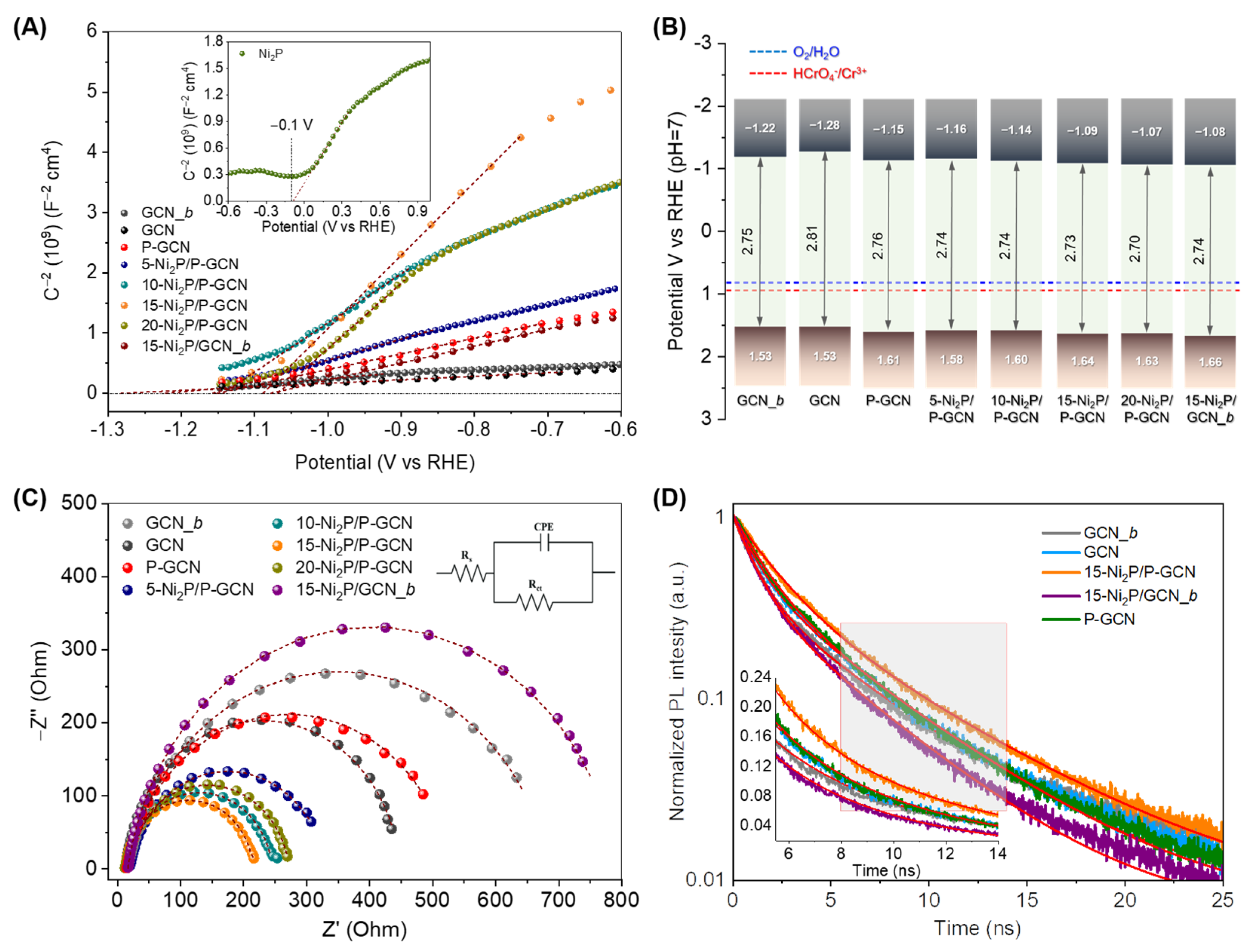
Figure 1. (A) Schematic display of the synthetic procedure of Ni2P-modified P-doped g-C3N4 (Ni2P/P-GCN) heterostructures. (B) Typical XRD patterns of Ni2P, GCN and Ni2P/P-GCN materials.
Catalysts 13 00437 g001
Figure 2. (A) FE-SEM images (Inset: high-magnification SEM image), (B) TEM image, (C) HRTEM (Inset: FFT pattern indexed to hexagonal P-62m Ni2P along the [100] zone axis) and (D) EDS elemental mapping images for 15-Ni2P/P-GCN catalyst.
Catalysts 13 00437 g002
Figure 3. Typical XPS spectra of (A) C 1s and (B) N 1s for GCN, P-GCN and 15-Ni2P/P-GCN. (C) P 2p XPS spectra of P-GCN and 15-Ni2P/P-GCN and (D) Ni 2p3/2 XPS spectrum of 15-Ni2P/P-GCN.
Catalysts 13 00437 g003
Figure 4. Photocatalytic reduction of aqueous Cr(VI) solution over (A) different catalysts (The time evolution of the Cr(VI) reduction over the 15-Ni2P/P-GCN catalyst in the dark is also given), (B) 15-Ni2P/P-GCN without and with the presence of various interfering ions (SO42−, CO32−, NO3−, Cl, Na+, Cu2+, Mn2+ and Zn2+) and (C) 15-Ni2P/P-GCN in the presence of three equivalents of phenol (PhOH), ethylenediaminetetraacetic acid (EDTA) and citric acid. (D) Recycling study of 15-Ni2P/P-GCN catalyst in the photocatalytic reduction of Cr(VI). All the photocatalytic experiments were performed as follows: 0.8 g·L−1 (or 0.4 g·L−1 for catalytic tests in panel A) catalyst, 50 mg·L−1 Cr(VI) solution, pH = 2, λ > 360 nm light irradiation, 20 °C.
Catalysts 13 00437 g004
Figure 5. (A) Mott–Schottky plots (Inset: the Mott–Schottky plot of the as-prepared Ni2P microparticles), (B) band-edge potentials and (C) Nyquist diagrams (Inset: Randles equivalent circuit model Rs[CPE/Rct], where Rs is the electrolyte resistance, Rct is the charge-transfer resistance and CPE is a constant phase element to account for the nonideality of the frequency dispersion in the capacitance response) for the various catalysts. (D) Time-resolved photoluminescence (TR-PL) decay profiles of GCN_b, GCN, P-GCN and Ni2P-modified catalyst with 15 wt.% Ni2P content. The inset shows an enlargement of the selected area.
Catalysts 13 00437 g005
Scheme 1. Proposed mechanism for the UV-visible induced photocatalytic reduction of Cr(VI) over the Ni2P/P-GCN catalysts.
Catalysts 13 00437 sch001
Table 1. Electrochemical results deduced from EIS analysis for various catalysts.
SampleEFB
(V vs. RHE)
EVB
(V vs. RHE)
Donor Density, ND
(cm−3)
Rct
(Ohm)
GCN_b−1.221.531.72 × 1018661
GCN−1.281.533.17 × 1018436
P-GCN−1.151.617.12 × 1017514
5-Ni2P/P-GCN−1.161.585.30 × 1017311
10-Ni2P/P-GCN−1.141.602.28 × 1017233
15-Ni2P/P-GCN−1.091.641.53 × 1017203
20-Ni2P/P-GCN−1.071.631.71 × 1017261
15-Ni2P/GCN_b−1.081.666.60 × 1017777
Disclaimer/Publisher’s Note: The statements, opinions and data contained in all publications are solely those of the individual author(s) and contributor(s) and not of MDPI and/or the editor(s). MDPI and/or the editor(s) disclaim responsibility for any injury to people or property resulting from any ideas, methods, instructions or products referred to in the content.

