Article

Metallic Supported Pd-Ag Membranes for Simultaneous Ammonia Decomposition and H2 Separation in a Membrane Reactor: Experimental Proof of Concept

by
Valentina Cechetto
1,†,
Serena Agnolin
1,†,
Luca Di Felice
1,
Alfredo Pacheco Tanaka
1,2,
Margot Llosa Tanco
1,2 and
Fausto Gallucci
1,3,*
1
Inorganic Membranes and Membrane Reactors, Sustainable Process Engineering, Department of Chemical Engineering and Chemistry, Eindhoven University of Technology, De Rondom 70, 5612 AP Eindhoven, The Netherlands
2
Tecnalia, Basque Research and Technology Alliance (BRTA), Mikeletegi Pasealekua 2, 20009 Donostia-San Sebastian, Spain
3
Eindhoven Institute for Renewable Energy Systems (EIRES), Eindhoven University of Technology, P.O. Box 513, 5600 MB Eindhoven, The Netherlands
*
Author to whom correspondence should be addressed.
These authors contributed equally to this work.
Catalysts 2023, 13(6), 920; https://doi.org/10.3390/catal13060920
Submission received: 25 April 2023 / Revised: 17 May 2023 / Accepted: 19 May 2023 / Published: 23 May 2023

Abstract

:
The use of ammonia as a hydrogen carrier requires efficient cracking technology. A promising solution is the use of a membrane reactor (MR), which enables both ammonia decomposition and hydrogen separation to take place within the same device, providing advantages in terms of efficiency and compactness compared to conventional systems. The literature reports that ceramic-supported double-skinned Pd-Ag membranes show outstanding performance for hydrogen separation as well as good stability of the separation layer during ammonia decomposition. However, their sealing in the reactor may result in leakage increase, while their mechanical stability remains an unresolved issue. To circumvent these limitations, the use of metallic supported Pd-based membranes is recommended, due to their higher mechanical stability and ease of sealing and integration in the reactor. In this work, we propose the development of robust metallic supported hydrogen-selective membranes for integration in membrane reactors for ammonia cracking. A conventional Pd-Ag membrane was prepared on a low-cost porous Hastelloy X tubular filter, modified with α-Al2O3/γ-Al2O3 to reach the desired surface quality. The membrane was then tested for ammonia decomposition in a MR configuration, showing the ability to reach >99% NH3 conversion above 475 °C with H2 feed recovery >60%. The results achieved pave the way towards a possible substitute for the ceramic-supported alternatives.

Graphical Abstract

1. Introduction

Hydrogen is a key component in many industrial processes and is a clean energy carrier that has the potential to replace fossil fuels in various applications [1,2,3,4,5]. However, the current methods employed for its production are primarily based on non-renewable sources and emit significant amounts of greenhouse gases [6]. To address this issue, alternative and more sustainable pathways for hydrogen production are nowadays explored. While green hydrogen can be easily produced via water electrolysis, hydrogen storage and transportation still pose challenges due to the lack of infrastructure and subsequent requirement of high-pressure storage.
A promising route for the storage, transportation and on-site production of sustainable hydrogen consists in the decomposition of green ammonia [7,8,9]. This process, which involves the breakdown of ammonia (NH3) into nitrogen (N2) and hydrogen (H2), has in fact several advantages compared to conventional systems for hydrogen production, the most important being that the process is not responsible for carbon emissions [10,11,12,13]. Furthermore, hydrogen production from ammonia decomposition allows to overcome the challenges related to hydrogen storage and distribution. The ease of liquefaction of ammonia compared to compressed hydrogen, its lower cost per unity of energy stored and its already existing infrastructure for storage and transportation make in fact this molecule a promising energy carrier and make ammonia decomposition an attractive solution for decentralized hydrogen production [8,9,10]. Particularly, the fact that ammonia is a carbon-free molecule, makes ammonia attractive for the production of carbon-free hydrogen to be used in carbon-sensitive applications such as PEM fuel cells [10,11,12,13,14,15,16,17,18,19].
To produce hydrogen from ammonia, first ammonia must be decomposed into hydrogen and nitrogen (according to Equation (1)), then hydrogen must be separated from nitrogen and unconverted ammonia. While these two steps require dedicated units in a conventional process, they can be simultaneously performed in a membrane reactor with advantages in terms of compactness of the system. Moreover, while ammonia conversion in a conventional reactor is favored at high temperature and low pressure, the use of a membrane reactor has proved to reduce the reactor operating temperature and increase the operating pressure compared to a conventional system, with advantages in terms of energy efficiency (due to low temperature) and compactness of reactor (due to high pressure) [15,20,21,22,23]. The selective separation of hydrogen from the reaction zone - which is favoured at high pressure - enhances in fact the reaction kinetics and shifts the reaction equilibrium towards the reaction products thereby increasing the conversion of the feedstock.
N H 3 0.5 N 2 + 1.5 H 2 H f o = 45.92 k J m o l
Hydrogen production via ammonia decomposition has already been experimentally investigated in several works available in literature [15,20,21,22,23,24,25,26,27,28,29,30,31,32,33,34,35] and the best performance in terms of NH3 conversion, hydrogen recovery and purity of hydrogen produced have been obtained when using a Ru-based catalyst to promote the ammonia decomposition reaction and ultra-thin ceramic supported “double skin” Pd-based membranes for hydrogen separation. Ceramic supported membranes in fact generally show very good performance for pure hydrogen separation, as the smooth surface of the ceramic support (with accurate control on porosity and narrow pore sizes distributions up to a few nanometers) facilitates the deposition of ultra-thin and defect-free palladium layers.
However, ceramic supported membranes are not easy to seal and couple to stainless-steel reactor modules [36]. Moreover, having the ceramic support a thermal expansion coefficient significantly different compared to that of palladium, they can be relatively easily damaged while working at high temperature, as cracks can form at the Pd/support interface [37]. These limitations make the commercialization of membrane reactors for ammonia decomposition more challenging. On the other hand, these challenges could be overcome using metallic supported membranes.
Steel and steel alloys materials have been investigated as potential candidates for a new generation of Pd-based membranes supports [38,39,40,41]. They in fact require only a simple weld to be sealed and are way less prone to breakage or crack formation thanks to their high mechanical stability. However, metal-based supports are characterized by rough surfaces, large superficial pore mouths, and wide pore size distribution, making membrane gas-tightness and H2 selectivity quite difficult to achieve during the Pd deposition step [42]. Metallic supports with the desired superficial characteristics therefore require extremely low media grades and specific supplier operated treatments, which increase their final costs. The challenging prices of metallic supports with suitable surface characteristics make the development of pre-treatments on low-cost steel-based filters a necessity for the commercialization of the MR ammonia cracking technology [33]. For this reason, this work focuses on modifying raw and cheaper tubular metallic filters and on converting them into a membrane support by filling the large, non-uniform pores with α-alumina particles of decreasing size.
Additionally, steel-based membrane supports present strong interaction with the deposited Pd film, a phenomenon known as intermetallic diffusion [43] (or Pd-support interaction). The diffusion of Pd in the support and vice versa can therefore hinder membrane H2 permeation performance, as well as long-term stability [41,43,44]. This additional challenge can be overcome by the addition of a ceramic-based (commonly Al2O3 [45,46], CeO [47,48], YSZ [38,49], ZrO2 [50,51]), interdiffusion barrier between the Pd film and the metallic support itself [52], which proves essential for the membrane’s functioning in reaction environment. Moreover, the addition of dopant metals, (e.g., Au, Cu) to the selective Pd layer could improve the membrane’s stability to a few ppm of feedstock pollutants such as H2S. However, it would not influence its thermal stability or separation performance, having the same effect as Ag addition [53,54]. In this work, we characterize a promising preparation procedure for Pd-Ag membranes on low-cost, rough Porous Hastelloy X filters, consisting in a support filling step with α-Al2O3 of decreasing size, and a boehmite based coating as interdiffusion barrier. By applying all the selected pre-treatments, we aim to demonstrate that hydrogen selective membranes fabricated from rough, porous Hastelloy X filters can be used for ammonia cracking applications, offering a first alternative to conventional ceramic supported membranes. The large pore size distribution and surface roughness of the selected filters renders the pre-treatments of the supports particularly challenging. However, the ceramic filler particle size and amount of filling cycles prove easily tunable parameters for the further improvement of membrane permeance, paving the way towards a standardized development procedure for Pd-based membranes supported on this kind of filters. Following the procedure characterization, we then test one of the membranes to assess its suitability for ammonia decomposition applications in a fixed bed membrane reactor.

2. Results and Discussion

2.1. Membrane Preparation

In Figure 1, the surface evolution of the membrane support filter with each pre-treatment is shown. The untreated filter presented superficial pore mouths larger than 50 µm, which were partially closed during the wet-polishing treatment (Figure 1a,b). At this stage, the surface roughness of the filter (Ra = 6.1 µm) was considerably reduced (Ra = 1.1 µm). However, the superficial porosity of the material was lost due to plastic deformation. In order to recover the gas permeance through the media and preserve the reduction in surface roughness, the polished layer was cracked open via chemical etching, as confirmed by the superficial cracks in Figure 1c. These cracks promote gas permeation while preserving the smoothening and closing effect of the polishing treatment. However, some of the largest pore mouths remained untouched by the selected pre-treatments. The depth of these valleys was filled with α-Al2O3 of decreasing size, promoting both surface leveling and pore size distribution reduction (Figure 1c). After the deposition of the interdiffusion barrier (Figure 1d), the average surface roughness, Ra, was reduced to 0.8 µm. In Figure 2 the cumulative flow distribution through the filter, obtained via CFP after each modification step, is shown. After the polishing and etching pre-treatments, the filter presented wide flow distribution and high permeance. However, after asymmetrically filling with α-Al2O3, the detected average pore diameter was 230 nm. The deposition of the interdiffusion barrier promoted further sharpening of the flow distribution towards pores of 90 nm. This value proved comparable to the target of 100 nm, representing the average pore diameter of a ceramic support for highly selective Pd-Ag membranes [55] for ammonia decomposition.
In Figure 3, the surface of a twin membrane is observed via confocal laser and optical microscopy. Particularly, the selected superficial section is fully closed by the deposited Pd-Ag layer. This is possible due to the filter pre-treatments and two-step modification, which guarantee the formation of the fully dense Pd-Ag layer on the selected filters.

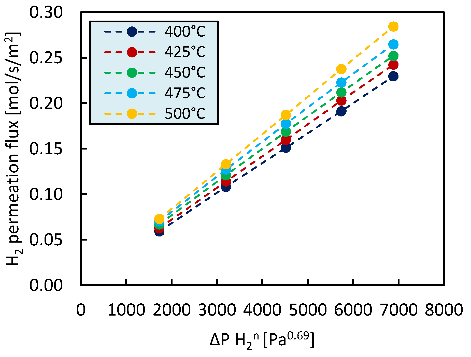
2.2. Single Gas Permeation Tests

The measured hydrogen and nitrogen permeances at 400, 450 and 500 °C and 1 bar pressure difference across the membrane are listed in Table 1 together with the corresponding ideal perm-selectivity. The experimental results show that H2 permeation significantly increases with increasing temperature, whereas N2 permeation is less significantly affected by a temperature variation. This results in increasing H2/N2 ideal-perm-selectivity when increasing temperature.
In Figure 4 the hydrogen flux through the membrane at different temperatures is represented as a function of the transmembrane pressure difference. The best fit for the hydrogen fluxes and hydrogen partial pressure difference across the membrane ( P H 2 n ) was found for a pressure exponent value of 0.69. In Pd-based membranes, the pressure exponent is 0.5 when the rate limiting step is diffusion through the bulk of palladium. A value of n deviating from 0.5 may indicate the presence of a contribution of the metallic support to the H2 transport mechanism, external mass transfer limitations, or limitations in the surface reactions [56,57].
From the hydrogen fluxes through the membrane measured in the temperature range between 400 °C and 500 °C the activation energy for hydrogen permeation through the membrane was then estimated to be 9.1 kJ/mol from the Arrhenius’ plot reported in Appendix A (Figure A3). This value is well in agreement with previously reported values of apparent activation energy for Pd-based membranes. The calculated value for activation energy lumps the effect of both the activation energy required for hydrogen permeation through the selective layer of the membrane and of the activation energy required for hydrogen to permeate through the membrane support.

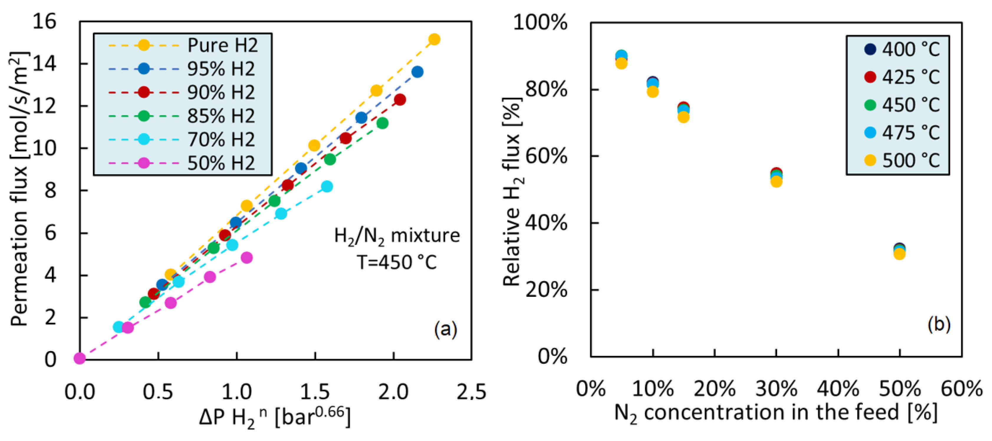
2.3. Binary Mixture (H2/N2) Permeation Tests

In Figure 5a the effect of a different hydrogen concentration in the feed mixture on the separation performance of the investigated Pd-based membrane is shown. Specifically, the permeation flux through the membrane is represented as a function of the hydrogen partial pressure difference across the membrane for a H2/N2 feed mixture containing a hydrogen concentration ranging between 50% and 95%. The results of the single gas hydrogen permeation tests are also reported and used as benchmark for comparison. The membrane separation performance is different compared to the case in which the pure hydrogen permeation test was performed. When N2 concentration in the feed mixture increases, a lower amount of hydrogen is available for separation and therefore, at constant pressure difference across the membrane, the hydrogen permeation flux through the membrane decreases. Moreover, a lower hydrogen partial pressure in the feed mixture results in lower driving force for hydrogen separation which in turn leads to lower hydrogen permeation. This discrepancy in the results arises from mass transfer limitation phenomena, known as concentration polarization, from which Pd-Ag membranes suffer. In line with literature, mass transfer limitations become more remarkable when the hydrogen concentration in the feed mixture decreases as well as when the pressure difference across the membrane increases. At higher total pressure difference across the membrane, the mass transfer limitation increases due to the higher flow through the membrane and the higher recovery. As a result of concentration polarization, a lower amount of hydrogen is recovered at constant hydrogen partial pressure difference across the membrane.
To investigate the effect of concentration polarization on hydrogen permeation, a relative flux was calculated as the ratio between the hydrogen flux measured when feeding the H2/N2 mixture and the hydrogen flux measured under pure hydrogen permeation tests. The relative fluxes as a function of the concentration of N2 in the feed are plotted in Figure 5b. It can be concluded that the membrane suffers from quite reduced flux even for low N2 concentration in the feed. Moreover, the higher the temperature the higher the mass transfer limitation effect. All Pd-based membranes show in fact higher hydrogen fluxes for increasing temperatures and the higher amount of hydrogen that permeates the higher the mass transfer limitation effect.

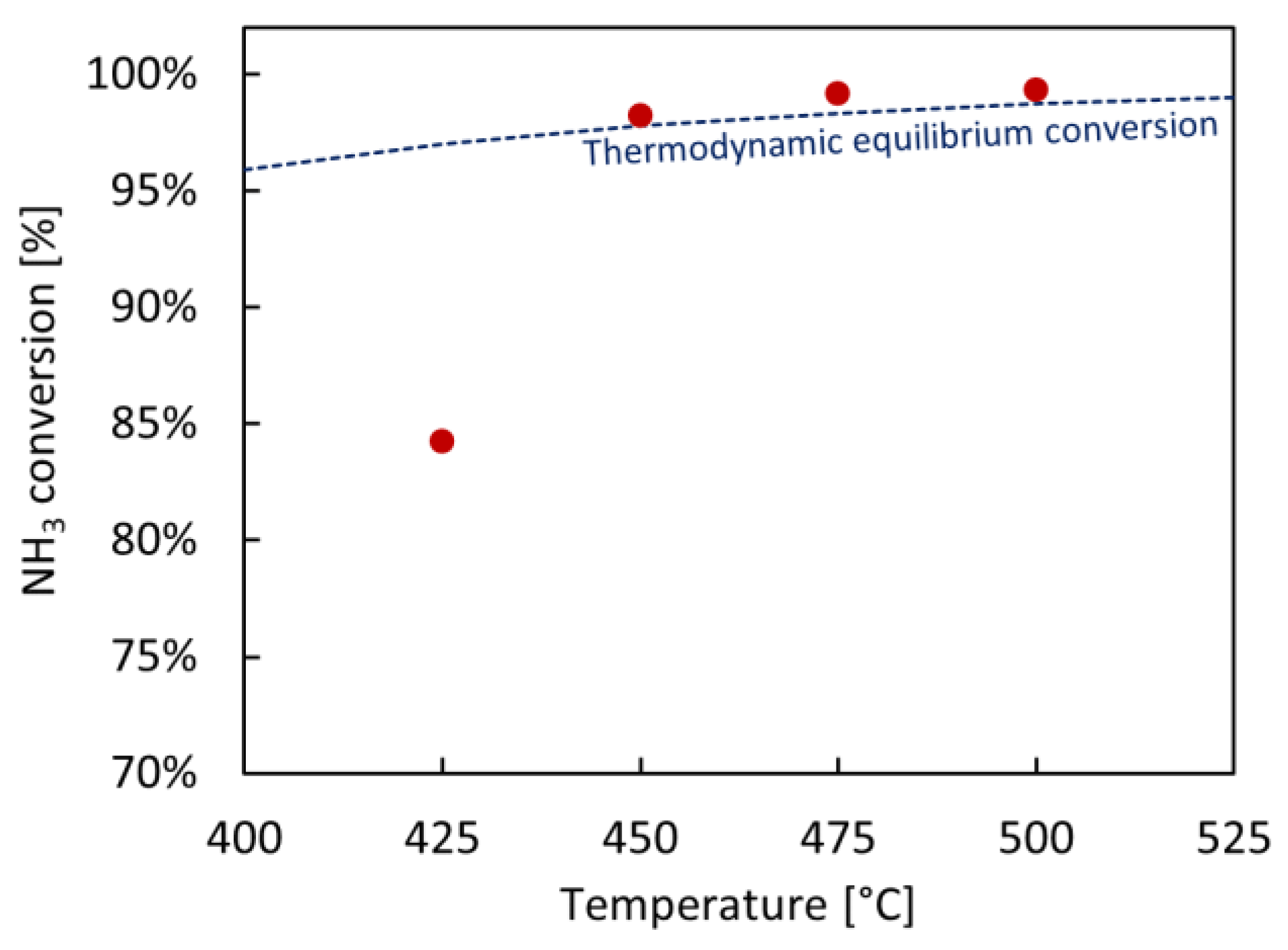
2.4. Permeation Tests under Reactive Conditions

The effect of temperature and pressure at which the ammonia decomposition reaction takes place on the performance of the membrane reactor has been investigated and the results are presented in Table 2 and Table 3, respectively.
From Table 2 it is possible to see that a temperature increase results in higher ammonia conversion as well as in higher recovery. The increase in ammonia conversion can be ascribed to the more favorable kinetics and thermodynamics of reaction when operating the reactor at high temperature, whereas the improved hydrogen recovery results from the higher hydrogen partial pressure in the reactor which in turn leads to higher driving force for hydrogen separation. Moreover, from Table 3 and Figure 6, it can be seen that NH3 conversion in the membrane reactor is higher than the calculated thermodynamic equilibrium conversion of the conventional reactor (without H2 separation membrane) for temperatures higher than 450 °C. Overall, these results are in agreement with other literature studies [15,20,21,22,23].
More specifically, a comparison between the results shown in Figure 6 and the ones obtained in our previous work [23] under similar operating conditions using a ceramic supported membrane is presented in Table 4. The lower H2 permeance and length of the membrane used in this work (10 cm, due to ease of preparation and handling) result in a decreased H2 recovery and NH3 conversion—the latter being particularly evident at the lowest temperature of 425 °C, while reaching >99% at T > 475 °C. Highly selective metallic supported membranes display in fact lower H2 permeance compared to the ceramic supported equivalents. This difference is to be attributed to the intrinsic difference in supports porosity, the necessity for a filler to reduce the metallic support’s large pore size distribution and, finally, the addition of a barrier to prevent Pd-support interaction phenomena [49,58].
In view of these results, this paper demonstrates for the first time that, despite the need to scale-up membrane length and possibly improve their H2 permeation properties, the proposed pre-treated metallic supports are a suitable alternative to ceramic ones for the fabrication of Pd-based, H2 selective membranes used in ammonia decomposition membrane reactors.
As it is possible to see from Table 3, hydrogen recovery can be improved increasing the reactor operating pressure, i.e., increasing the driving force for hydrogen separation. It is worth noticing that, while in a conventional system a pressure increase has a significant negative impact on NH3 conversion, in the investigated pressure range in the membrane reactor the decrease in NH3 conversion due to increasing pressure is minor. The decrease in NH3 conversion that is expected at high pressure according to the Le Châtelier’s principle is in fact counterbalanced by the fact that a pressure increase improves the hydrogen removal from the reaction zone resulting in faster kinetics and shifted thermodynamics which in turn enhance ammonia conversion.
In case of application in PEM fuel cells, according to ISO 14687:2019 [59], NH3 concentration in the hydrogen stream must not exceed 0.1 ppm. While the residual NH3 concentration in the hydrogen stream has not been evaluated in this work, it has already been demonstrated in literature that commercially available adsorbent materials [12,16,31,60,61,62,63] or ion-exchange forms of different type of zeolites [63,64,65,66] can be used to reduce the residual ammonia concentration in the hydrogen stream to levels that are suitable for PEM fuel cell application.
A comparison between the experimental results achieved in this work and others available in recent literature is presented in Table 5. The table lists information about the configuration of the membrane used for hydrogen separation, operating conditions of the membrane reactor, catalyst employed, and the best results achieved in each work. By “best results” we intend the results that facilitated efficient membrane reactor operation, which includes NH3 conversion greater than 99% and H2 recovery above 90%. Alternatively, when optimal reactor operation was not achieved, the results that were the closest to this target were reported. The results achieved in this work demonstrate that hydrogen selective membranes fabricated from low-cost porous Hastelloy-X filters offer an alternative to conventional ceramic and other metallic supported membranes. Similarly to other works available in literature, in fact, NH3 conversion >99% was achieved. On the other hand, the H2 recovery achieved in this work is sensibly lower compared to the one achieved in other studies. This can be related to the combination of multiple aspects, which are mainly related to the fact that the performance of a MR for H2 production from NH3 not only depend on the reactor operating conditions, but also on the membrane properties and separation performance. Specifically, while the large pore size of the filter requires filler introduction to ensure membrane selectivity, an additional barrier is needed to prevent metallic interdiffusion, which contributes to relatively low hydrogen permeation. Furthermore, the membrane area installed in this study is relatively low (membrane length ~10 cm), which also results in lower H2 recovery factors. Given the different operating conditions at which the experimental results reported in Table 5 have been achieved, a direct quantitative comparison between the results achieved in this work and works available in literature proves challenging. Nonetheless, H2 recoveries comparable to values achieved in literature could be achieved by compensating for the reduced H2 permeance with larger installed membrane area. Additionally, as the NH3 conversion enhancement compared to a system in which no membrane is used is proportional to the H2 permeation through the membrane, the installation of a larger membrane area is also expected to further increase NH3 conversion, which in turn would also contribute to favor H2 recovery.
Lastly, in order to show the impact of membrane exposure at high temperature and to ammonia decomposition reaction on the membrane separation performance, in Figure 7 the ideal H2/N2 perm-selectivity of the membrane at 450 °C and 4 bar(a) is represented as a function of time. As it is possible to see, the ideal H2/N2 perm-selectivity decreases over time, indicating that during the experimental campaign defects have formed on the membrane surface or on the sealings, resulting in permeation of a higher amount of impurities (N2) through the membrane walls. Specifically, over a time of 360 h the H2/N2 ideal perm-selectivity decreased from 4807 to 3017. This decrease could be improved both by tuning the support pre-treatments (e.g. the α-Al2O3 filler particle size and filling cycles combination) and interdiffusion barrier (e.g. layer thickness) or via deposition of a “double-skin” mesoporous layer (γ-Al2O3-YSZ) onto the Pd surface, similarly to the membrane tested in our previous work ([5]) in order to fully close possible defects forming on the Pd layer.

3. Materials and Methods

3.1. Membrane Preparation

A commercial unrefined porous Hastelloy X filter with an outer diameter of 1.2 cm, average surface roughness (Ra) of 6.1 µm, and 0.5 µm nominal media grade (MG) was acquired from Hebei Golden Flame Wire Mesh Co, China. The filter was cut to 10 cm length and welded to dense stainless steel (AISI316L) tubes, to achieve a dead-end configuration (Figure 8).
The filter’s surface was then modified according to the procedure reported below and illustrated in Figure 9:
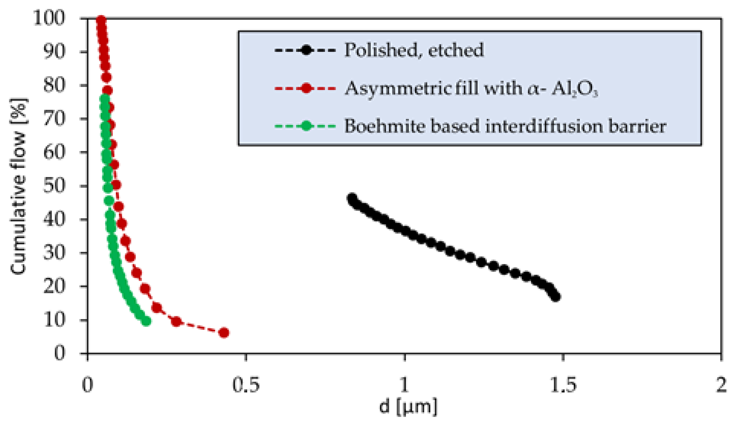
  • The rough filter was polished in an industrial surface finishing machine via wet-polishing mechanism (ERBA EVT-170) for 6 h, delivering a suitable trade-off between surface roughness reduction and gas permeation preservation [42]. The polished support was then vertically submerged in aqua regia for 30 s, to recover the lost superficial porosity. After the acid attack, the filter was thoroughly rinsed with deionized water to remove all mordant residuals. An oxidation in static air atmosphere was then performed in a furnace for 1 h at 750 °C, with heating rate 2 °C/min.
  • The support’s superficial pore size was improved by filling asymmetrically with α-Al2O3 of decreasing particle size via immersion in a magnetically stirred α-Al2O3-H2O suspension, improved by addition of HNO3 (67 vol.%) dropwise. The filler was pulled through the superficial pores via vacuum-assisted dip coating, with a lower wait time of 60 s per immersion cycle. Between each cycle the support was gently rinsed with distilled water. 20 aspiration cycles were performed with alumina 18 µm (AA-18, Sumitomo), 10 aspiration cycles with alumina 5 µm (AA-5, Sumitomo) and 10 with alumina 1.5 µm (AA-1, Sumitomo).
  • Finally, a mesoporous smoothening interdiffusion barrier was deposited to complete the improvement of support’s surface uniformity. A solution with boehmite loading 0.9 wt.% was prepared in distilled water, incorporating a water-based solution of organic additives, namely 3.5 wt.% polyvinyl alcohol (PVA) (MW 130,000) and 1 wt.% polyethylene glycol (PEG) (MW 400). The deposited layer was dried under rotation in a climate chamber at 40 °C and 60% relative humidity for 1 h and sintered for 1 h at 550 °C in a static air furnace.
A layer of Pd-Ag alloy is deposited onto the treated support via a 5 h electroless plating procedure, reported in a previous work by Tanaka et al. [67,68] up to a 6–8 µm thick Pd-Ag layer.

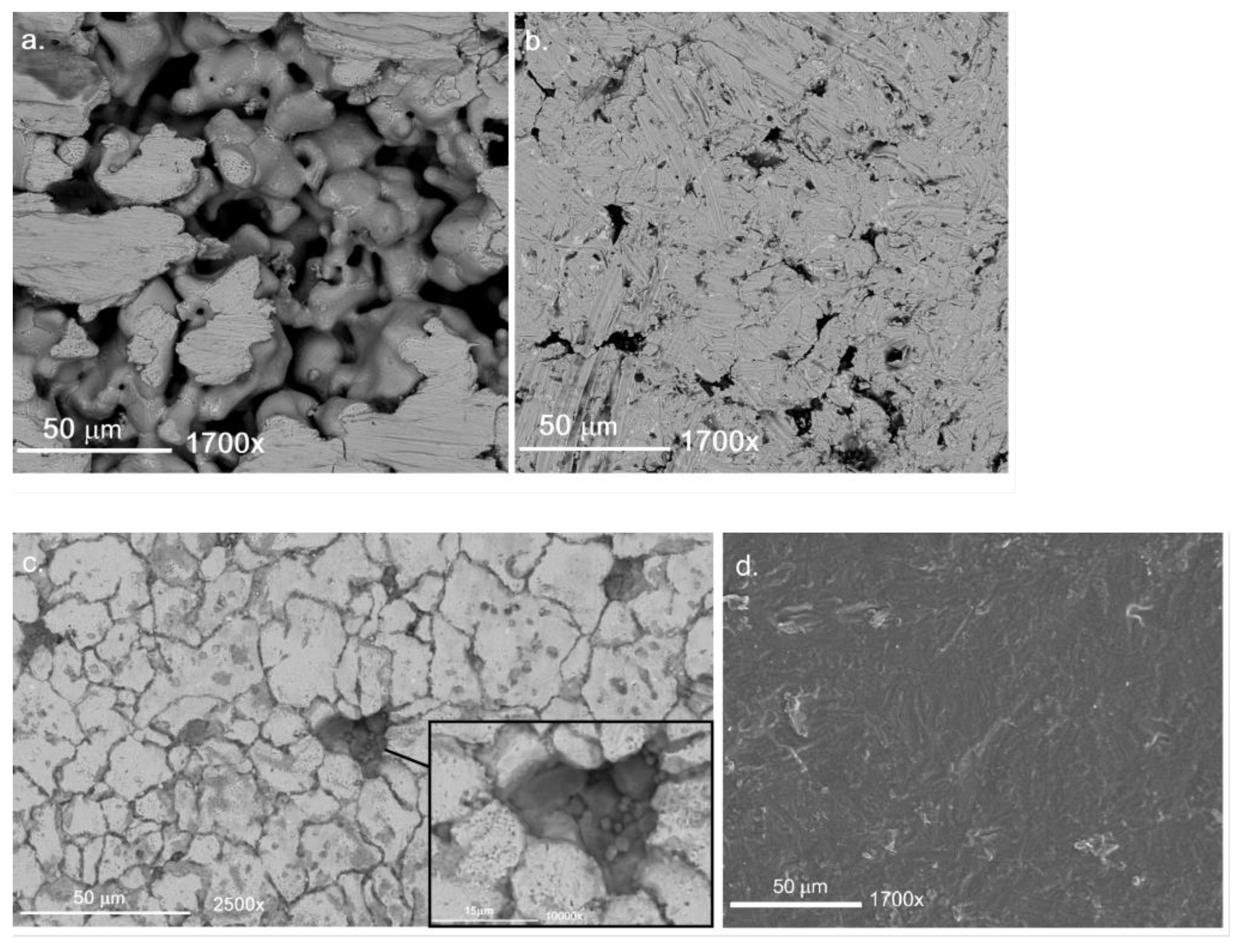
3.2. Membrane Characterizations

The evolution of support’s surface parameters was monitored through the membrane’s preparation procedure with different techniques. The surface roughness of the support was measured via contact profilometry (MarSurf PS 10). The superficial pore diameter distribution of the untreated, pre-treated and modified Hastelloy support were measured by capillary flow porometry (CFP or gas-liquid displacement) technique, in the setup reported in Appendix A, Figure A1. The surface of twin sample supports was observed via Scanning Electron Microscopy (SEM, Phenom Pro, ThermoFisher, The Netherlands). In order to preserve the metallographic structure of the porous metal, the samples were prepared via scoring and breakage of the membrane and observed as is. The membrane surface after Pd deposition was then observed via optical-laser confocal microscopy (VKX-3000, Keyence, Japan), to avoid sample breakage.

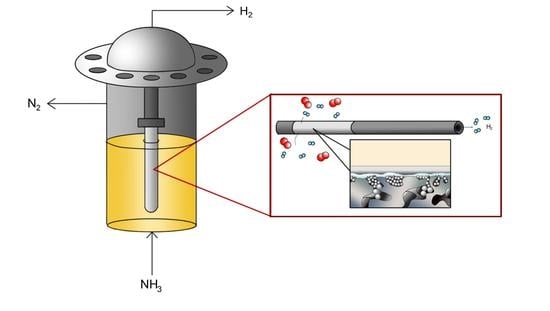
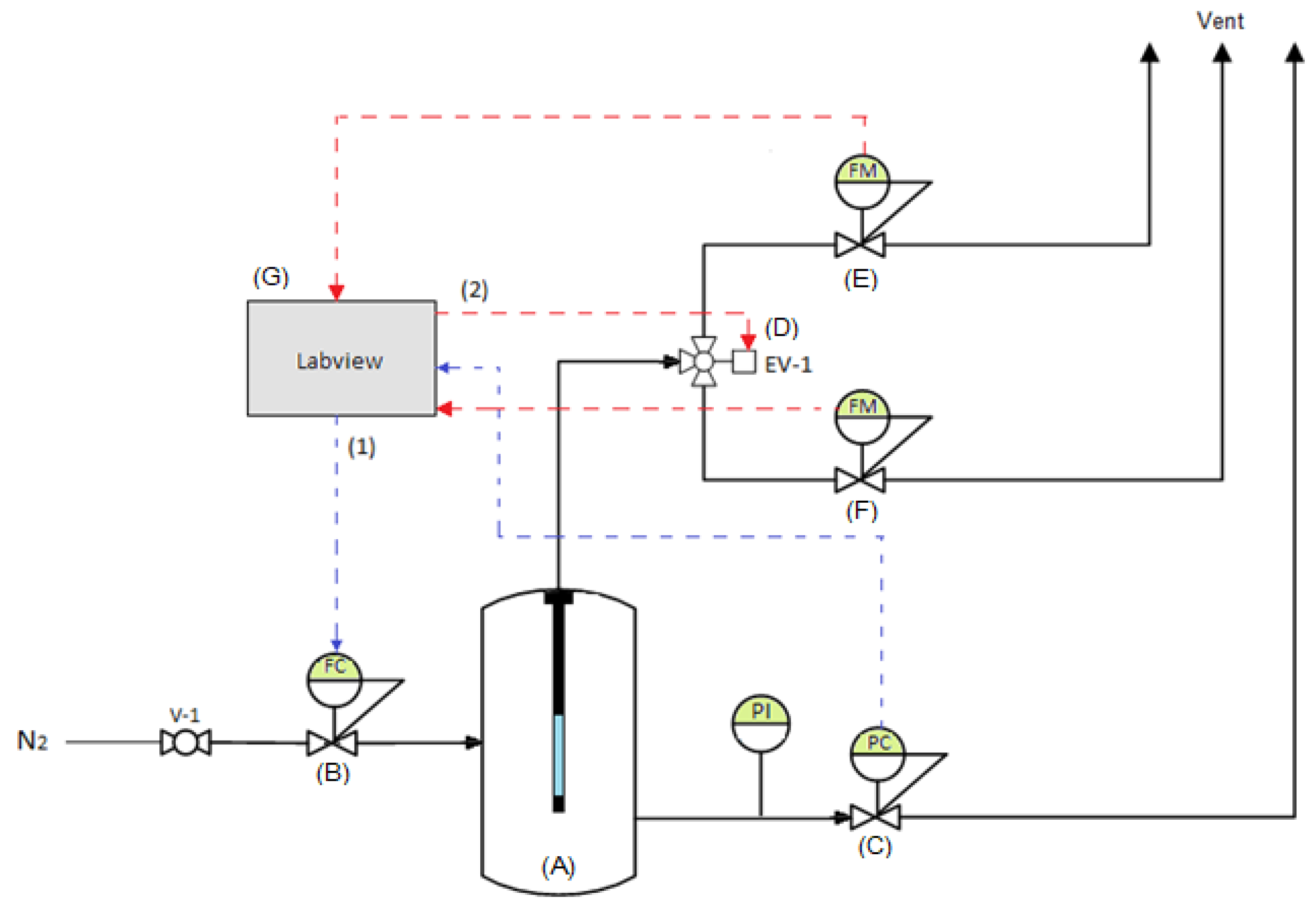
3.3. Experimental Setup for Permeation and Ammonia Decomposition

Ammonia decomposition tests have been performed in a tubular membrane reactor in which the membrane was fully immersed in a packed bed of catalyst. The reactor is made of stainless-steel and has an inner diameter of 4.5 cm and a length of 28 cm. Since ammonia decomposition is an endothermic reaction, heat is supplied to the reactor by an electrical split oven with three heating sections independently controlled. A porous stainless-steel plate at the bottom of the reactor was used to ensure uniform gas distribution at the reactor inlet, whereas at the freeboard of the catalytic bed the reactor has a conical shape to reduce the gas velocity and minimize the risk of catalyst particle escape during the experiments. The feed gases (NH3, H2 and N2) were controlled by mass flow controllers (Bronkhorst) and the pressure of the system was controlled by means of a back pressure regulator. The permeate side of the membrane was connected to a film-flow meter (Horiba Stec VP3/VP4) to determine the permeation flux. The retentate side of the membrane, after passing through a gas filter which aims at protecting the downstream equipment from fine particles, was sent to a μ-GC (Varian CP-4900) to measure its composition. The retentate and permeate lines were subsequently mixed and sent to a water absorption unit in which possible traces of NH3 are absorbed preventing their release in atmosphere. In this study, for hydrogen separation the metallic supported Pd-based membrane described in the previous section has been used. The membrane was fully immersed in a packed bed of 250 g of a commercial (2 wt.%) Ru/Al2O3 catalyst in pelletized form (3 mm) from Alfa Aesar. Characterization of such a catalyst before and after test has been previously discussed (supplementary data of [23]). A schematic representation of the setup used in this work is given in Appendix A, Figure A2.

3.4. Experimental Methods

Before its integration in the reactor, the membrane was sealed with graphene tape and a pressed 1.3 cm stainless steel ring, in order to exclude any possible leaks from the welding cord at the dead-end cap. The membrane was then tested in helium/ethanol in order to verify the absence of undesired leakages from both the sealing and Pd-Ag surface. As no leakages were detected, the membrane was subsequently installed in the membrane reactor. The reactor was then heated up to 500 °C at a heating rate of 2 °C/min in N2 atmosphere and activated by feeding the reactor with a hydrogen stream, as indicated in [69,70]. The activation was considered complete when hydrogen permeation was measured to be stable. The following tests have subsequently been performed: single gas (H2 and N2) and binary mixture (H2/N2) permeation tests, as well as permeation tests under reactive conditions. More details about the membrane testing procedure are given in the following sub-sections and an overview of the experimental conditions investigated in this work is presented in Table 6. In order to assess the membrane’s stability during exposure at high temperature and to ammonia decomposition reaction, single gas H2 and N2 permeation tests have been periodically performed at 450 °C and 4 bar(a) during the experimental campaign.

3.4.1. Single Gas (H2 and N2) Permeation Tests

Pure H2 and N2 gas permeation measurements were carried out in order to determine the ideal H2/N2 perm-selectivity of the membrane. The H2 and N2 permeation fluxes were measured for temperatures ranging between 400 °C and 500 °C and pressures ranging between 2 and 6 bar(a), keeping the permeate side of the membrane at atmospheric conditions. The H2 and N2 permeances, the ideal H2/N2 perm-selectivity as well as the activation energy for hydrogen permeation through the membrane were then calculated.

3.4.2. Binary Mixture (H2/N2) Permeation Tests

Binary mixture permeation tests were performed in order to compare the hydrogen flux available at the permeate side of the membrane at different hydrogen concentrations in the feed mixture. Specifically, permeation tests were carried out for H2/N2 mixture containing H2 concentrations ranging between 50 vol.% and 95 vol.%. For each binary mixture composition, the hydrogen permeation through the membrane was evaluated for temperatures and pressures ranging between 400 °C and 500 °C, and 2 bar(a) and 6 bar(a), respectively. The permeate side of the membrane was kept at atmospheric conditions.

3.4.3. Permeation Tests under Reactive Conditions

Ammonia decomposition has been performed for temperatures ranging between 425 °C and 500 °C, pressures in the range between 3 bar(a) and 6 bar(a) and under a feed flow rate of 0.5 LN/min of pure ammonia. The permeate side of the membrane was kept at atmospheric conditions. The experiments have been carried out according to the following procedure. At the desired temperature, pure ammonia was fed into the reactor and the operating pressure was adjusted. The reaction performance was then monitored until steady state operation was observed. The permeate flow rate and the composition of the stream leaving at the retentate side of the membrane were then measured 5 times and from each measurement NH3 conversion and H2 recovery were calculated. The values of NH3 conversion and H2 recovery reported in this work for a given combination of experimental conditions are the average of the 5 calculated values of NH3 conversion and H2 recovery. NH3 conversion was calculated according to equation 2 as the ratio between the amount of ammonia that in the reactor decomposes into hydrogen and nitrogen and the amount of ammonia that is fed to the reactor, whereas H2 recovery was calculated according to equation 3 as the ratio between the amount of hydrogen permeating through the membrane and the total amount of hydrogen that is fed into the reactor in the form of ammonia.
NH 3   conversion = N H 3 , i n N H 3 , o u t N H 3 , i n
H 2   recovery = H 2 , p e r m e a t e 1.5 N H 3 , i n

4. Conclusions

An innovative membrane, consisting of a Pd-Ag selective layer successfully supporting a 6 μm rough metallic filter with 0.5 μm media grade and 50 μm pore mouths, has been prepared. The selected pre-treatments proved suitable to achieve a support with a superficial pore size of ~90 nm, resulting in the membrane’s H2/N2 ideal selectivity at 500 °C and 1 bar of ~38,000. The H2/N2 mixture permeation tests showed an effect of concentration polarization on the H2 permeation across the membrane, resulting in lower H2 fluxes when N2 concentration in the feed is increased, well in agreement with Pd-based membrane behavior reported in the literature. The tests in an ammonia cracking environment showed the ability to overcome the conventional thermodynamic conversion of NH3 when the selected membrane is introduced, reaching NH3 conversions >99% for temperatures including and above 475 °C. The hydrogen recovered from the feed amounts to >60% for the same temperature range, considering the membrane being solely 10 cm long.
Finally, a stability test performed at 4 bar for 360 h showed a decrease in the corresponding membrane ideal H2/N2 selectivity from ~4800 to ~3000, showing possible defect formation in long-term conditions, highlighting the need for further tuning of the metallic support prior to treatments.
Overall, the promising results show that the selected membrane preparation procedure is proven suitable for the further development of Pd-based membranes for NH3 cracking on steel/steel alloy supports.

Author Contributions

Conceptualization, V.C. and S.A.; methodology, V.C. and S.A.; investigation, V.C.; resources, S.A.; data curation, V.C. and S.A.; writing—original draft preparation, V.C. and S.A.; These authors contributed equally to this work. Writing—review and editing, L.D.F. and F.G.; visualization, V.C. and S.A.; supervision, L.D.F., F.G., A.P.T. and M.L.T.; project administration, F.G.; funding acquisition, F.G. All authors have read and agreed to the published version of the manuscript.

Funding

This project has received funding from the European Union’s Horizon 2020 Research and Innovation Programme under grant agreements No. 869896 (MACBETH) and No. 862482 (ARENHA) Catalysts 13 00920 i001

Data Availability Statement

Data are available on request.

Conflicts of Interest

The authors declare no conflict of interest. The funders had no role in the design of the study; in the collection, analyses, or interpretation of data; in the writing of the manuscript; or in the decision to publish the results.

Sample Availability

Samples of the Hastelloy supported Pd-Ag membrane and are available from the authors.

Appendix A

Figure A1. Capillary flow porometry (CFP) setup. (A) Tubular permeation box able to withstand pressures up to 60 bara; (B) Automatic mass flow controller for N2 (Bronkhorst EL-FLOW Select F-221M), (C) Automatic backpressure regulator at the retentate side (Bronkorst EL-PRESS-P-502C); (D) Automatic three way valve, which can switch between a (E) low-flow automatic flowmeter (Bronkhorst EL-FLOW Prestige FG-111B, range 0.004 mL/min0.2 L/min) and a (F) high-flow automatic flowmeter (Bronkhorst EL-FLOW Prestige FG-111B range 0.2 L/min–10 L/min); (G) external computer with LabVIEW software for setup automation: the correct feed flow is sent to the permeation box in order to increase the pressure according to a ramp set by the user (1); the permeating flow at each timestamp is registered at the permeate side by the flowmeter with the correct flow range, automatically selected via the three-way valve (2).
Catalysts 13 00920 g0a1
Figure A2. NH3 decompostion setup.
Catalysts 13 00920 g0a2
Figure A3. Arrhenius plot based on H2 permeance after membrane activation.
Catalysts 13 00920 g0a3

References

  1. Dell, R.M.; Bridger, N.J. Hydrogen—The ultimate fuel. Appl. Energy 1975, 1, 279–292. [Google Scholar] [CrossRef]
  2. Rosen, M.A.; Koohi-Fayegh, S. The prospects for hydrogen as an energy carrier: An overview of hydrogen energy and hydrogen energy systems. Energy Ecol. Environ. 2016, 1, 10–29. [Google Scholar] [CrossRef]
  3. Abe, J.O.; Popoola, A.P.I.; Ajenifuja, E.; Popoola, O.M. Hydrogen energy, economy and storage: Review and recommendation. Int. J. Hydrog. Energy 2019, 44, 15072–15086. [Google Scholar] [CrossRef]
  4. Bockris, J.O.M. The hydrogen economy: Its history. Int. J. Hydrog. Energy 2013, 38, 2579–2588. [Google Scholar] [CrossRef]
  5. Johnston, B.; Mayo, M.C.; Khare, A. Hydrogen: The energy source for the 21st century. Technovation 2005, 25, 569–585. [Google Scholar] [CrossRef]
  6. IEA. The Future of Hydrogen; IEA: Paris, France, 2019. [Google Scholar]
  7. Lan, R.; Tao, S. Ammonia as a Suitable Fuel for Fuel Cells. Front. Energy Res. 2014, 2, 35. [Google Scholar] [CrossRef]
  8. Lamb, K.E.; Dolan, M.D.; Kennedy, D.F. Ammonia for hydrogen storage; A review of catalytic ammonia decomposition and hydrogen separation and purification. Int. J. Hydrog. Energy 2019, 44, 3580–3593. [Google Scholar] [CrossRef]
  9. Klerke, A.; Christensen, C.; Nørskov, J.; Vegge, T. Ammonia for hydrogen storage: Challenges and opportunities. J. Mater. Chem. 2008, 18, 2304–2310. [Google Scholar] [CrossRef]
  10. Valera-Medina, A.; Xiao, H.; Owen-Jones, M.; David, W.I.F.; Bowen, P.J. Ammonia for power. Prog. Energy Combust. Sci. 2018, 69, 63–102. [Google Scholar] [CrossRef]
  11. Valera-Medina, A.; Amer-Hatem, F.; Azad, A.K.; Dedoussi, I.C.; De Joannon, M.; Fernandes, R.X.; Glarborg, P.; Hashemi, H.; He, X.; Mashruk, S.; et al. Review on Ammonia as a Potential Fuel: From Synthesis to Economics. Energy Fuels 2021, 35, 6964–7029. [Google Scholar] [CrossRef]
  12. Cha, J.; Jo, Y.S.; Jeong, H.; Han, J.; Nam, S.W.; Song, K.H.; Yoon, C.W. Ammonia as an efficient COX-free hydrogen carrier: Fundamentals and feasibility analyses for fuel cell applications. Appl. Energy 2018, 224, 194–204. [Google Scholar] [CrossRef]
  13. Sørensen, R.Z.; Nielsen, L.J.; Jensen, S.; Hansen, O.; Johannessen, T.; Quaade, U.; Christensen, C.H. Catalytic ammonia decomposition: Miniaturized production of COx-free hydrogen for fuel cells. Catal. Commun. 2005, 6, 229–232. [Google Scholar] [CrossRef]
  14. Li, G.; Kanezashi, M.; Tsuru, T. Highly enhanced ammonia decomposition in a bimodal catalytic membrane reactor for COx-free hydrogen production. Catal. Commun. 2011, 15, 60–63. [Google Scholar] [CrossRef]
  15. Zhang, J.; Xu, H.; Li, W. High-purity COx-free H2 generation from NH3 via the ultra permeable and highly selective Pd membranes. J. Memb. Sci. 2006, 277, 85–93. [Google Scholar] [CrossRef]
  16. Chellappa, A.S.; Fischer, C.M.; Thomson, W.J. Ammonia decomposition kinetics over Ni-Pt/Al2O3 for PEM fuel cell applications. Appl. Catal. A Gen. 2002, 227, 231–240. [Google Scholar] [CrossRef]
  17. Le, T.A.; Kim, Y.; Kim, H.W.; Lee, S.U.; Kim, J.R.; Kim, T.W.; Lee, Y.J.; Chae, H.J. Ru-supported lanthania-ceria composite as an efficient catalyst for COx-free H2 production from ammonia decomposition. Appl. Catal. B Environ. 2021, 285, 119831. [Google Scholar] [CrossRef]
  18. Staffell, I.; Scamman, D.; Abad, A.V.; Balcombe, P.; Dodds, P.E.; Ekins, P.; Shah, N.; Ward, K.R. The role of hydrogen and fuel cells in the global energy system. Energy Environ. Sci. 2019, 12, 463–491. [Google Scholar] [CrossRef]
  19. Yin, S.F.; Xu, B.Q.; Zhou, X.P.; Au, C.T. A mini-review on ammonia decomposition catalysts for on-site generation of hydrogen for fuel cell applications. Appl. Catal. A Gen. 2004, 277, 1–9. [Google Scholar] [CrossRef]
  20. Zhang, Z.; Liguori, S.; Fuerst, T.F.; Way, J.D.; Wolden, C.A. Efficient Ammonia Decomposition in a Catalytic Membrane Reactor to Enable Hydrogen Storage and Utilization. ACS Sustain. Chem. Eng. 2019, 7, 5975–5985. [Google Scholar] [CrossRef]
  21. Itoh, N.; Oshima, A.; Suga, E.; Sato, T. Kinetic enhancement of ammonia decomposition as a chemical hydrogen carrier in palladium membrane reactor. Catal. Today 2014, 236, 70–76. [Google Scholar] [CrossRef]
  22. Itoh, N.; Kikuchi, Y.; Furusawa, T.; Sato, T. Tube-wall catalytic membrane reactor for hydrogen production by low-temperature ammonia decomposition. Int. J. Hydrog. Energy 2020, 46, 20257–20265. [Google Scholar] [CrossRef]
  23. Cechetto, V.; Di Felice, L.; Medrano, J.A.; Makhloufi, C.; Zuniga, J.; Gallucci, F. H2 production via ammonia decomposition in a catalytic membrane reactor. Fuel Process. Technol. 2021, 216, 106772. [Google Scholar] [CrossRef]
  24. Rizzuto, E.; Palange, P.; Del Prete, Z. Characterization of an ammonia decomposition process by means of a multifunctional catalytic membrane reactor. Int. J. Hydrog. Energy 2014, 39, 11403–11410. [Google Scholar] [CrossRef]
  25. Israni, S.H.; Nair, B.K.R.; Harold, M.P. Hydrogen generation and purification in a composite Pd hollow fiber membrane reactor: Experiments and modeling. Catal. Today 2009, 139, 299–311. [Google Scholar] [CrossRef]
  26. Li, G.; Kanezashi, M.; Lee, H.R.; Maeda, M.; Yoshioka, T.; Tsuru, T. Preparation of a novel bimodal catalytic membrane reactor and its application to ammonia decomposition for COx-free hydrogen production. Int. J. Hydrog. Energy 2012, 37, 12105–12113. [Google Scholar] [CrossRef]
  27. Park, Y.; Cha, J.; Oh, H.T.; Lee, T.; Lee, S.H.; Park, M.G.; Jeong, H.; Kim, Y.; Sohn, H.; Nam, S.W.; et al. A catalytic composite membrane reactor system for hydrogen production from ammonia using steam as a sweep gas. J. Memb. Sci. 2020, 614, 118483. [Google Scholar] [CrossRef]
  28. Jo, Y.S.; Cha, J.; Lee, C.H.; Jeong, H.; Yoon, C.W.; Nam, S.W.; Han, J. A viable membrane reactor option for sustainable hydrogen production from ammonia. J. Power Sources 2018, 400, 518–526. [Google Scholar] [CrossRef]
  29. Liu, J.; Ju, X.; Tang, C.; Liu, L.; Li, H.; Chen, P. High performance stainless-steel supported Pd membranes with a finger-like and gap structure and its application in NH3 decomposition membrane reactor. Chem. Eng. J. 2020, 388, 124245. [Google Scholar] [CrossRef]
  30. Jiang, J.; Dong, Q.; McCullough, K.; Lauterbach, J.; Li, S.; Yu, M. Novel hollow fiber membrane reactor for high purity H2 generation from thermal catalytic NH3 decomposition. J. Memb. Sci. 2021, 629, 119281. [Google Scholar] [CrossRef]
  31. Cechetto, V.; Di Felice, L.; Martinez, R.G.; Plazaola, A.A.; Gallucci, F. Ultra-pure hydrogen production via ammonia decomposition in a catalytic membrane reactor. Int. J. Hydrog. Energy 2022, 47, 21220–21230. [Google Scholar] [CrossRef]
  32. Cerrillo, J.L.; Morlanés, N.; Kulkarni, S.R.; Realpe, N.; Ramírez, A.; Katikaneni, S.P.; Paglieri, S.N.; Lee, K.; Harale, A.; Solami, B.; et al. High purity, self-sustained, pressurized hydrogen production from ammonia in a catalytic membrane reactor. Chem. Eng. J. 2022, 431, 134310. [Google Scholar] [CrossRef]
  33. Kim, T.W.; Lee, E.H.; Byun, S.; Seo, D.W.; Hwang, H.J.; Yoon, H.C.; Kim, H.; Ryi, S.K. Highly selective Pd composite membrane on porous metal support for high-purity hydrogen production through effective ammonia decomposition. Energy 2022, 260, 125209. [Google Scholar] [CrossRef]
  34. Sitar, R.; Shah, J.; Zhang, Z.; Wikoff, H.; Way, J.D.; Wolden, C.A. Compact ammonia reforming at low temperature using catalytic membrane reactors. J. Memb. Sci. 2022, 644, 120147. [Google Scholar] [CrossRef]
  35. Omata, K.; Sato, K.; Nagaoka, K.; Yukawa, H.; Matsumoto, Y.; Nambu, T. Direct high-purity hydrogen production from ammonia by using a membrane reactor combining V-10mol%Fe hydrogen permeable alloy membrane with Ru/Cs2O/Pr6O11 ammonia decomposition catalyst. Int. J. Hydrog. Energy 2022, 47, 8372–8381. [Google Scholar] [CrossRef]
  36. Alique, D.; Martinez-Diaz, D.; Sanz, R.; Calles, J.A. Review of supported pd-based membranes preparation by electroless plating for ultra-pure hydrogen production. Membranes 2018, 8, 5. [Google Scholar] [CrossRef]
  37. Nooijer, N.D.; Arratibel Plazaola, A.; Meléndez Rey, J.; Fernandez, E.; Pacheco Tanaka, D.A.; Sint Annaland, M.V.; Gallucci, F. Long-term stability of thin-film Pd-based supported membranes. Processes 2019, 7, 106. [Google Scholar] [CrossRef]
  38. Straczewski, G.; Völler-Blumenroth, J.; Beyer, H.; Pfeifer, P.; Steffen, M.; Felden, I.; Heinzel, A.; Wessling, M.; Dittmeyer, R. Development of thin palladium membranes supported on large porous 310L tubes for a steam reformer operated with gas-to-liquid fuel. Chem. Eng. Process. Process Intensif. 2014, 81, 13–23. [Google Scholar] [CrossRef]
  39. Mateos-Pedrero, C.; Soria, M.A.; Rodríguez-Ramos, I.; Guerrero-Ruiz, A. Modifications of Porous Stainless Steel Previous to the Synthesis of Pd Membranes; Elsevier Masson SAS: Issy-les-Moulineaux, France, 2010; Volume 175. [Google Scholar]
  40. Do, H.Y.; Kim, C.H.; Han, J.Y.; Kim, H.S.; Ryi, S.K. Low-temperature proton-exchange membrane fuel cell-grade hydrogen production by membrane reformer equipped with Pd-composite membrane and methanation catalyst on permeation stream. J. Memb. Sci. 2021, 634, 119373. [Google Scholar] [CrossRef]
  41. Nayebossadri, S.; Fletcher, S.; Speight, J.D.; Book, D. Hydrogen permeation through porous stainless steel for palladium-based composite porous membranes. J. Memb. Sci. 2016, 515, 22–28. [Google Scholar] [CrossRef]
  42. Agnolin, S.; Melendez, J.; Di Felice, L.; Gallucci, F. Surface roughness improvement of Hastelloy X tubular filters for H2 selective supported Pd–Ag alloy membranes preparation. Int. J. Hydrog. Energy 2022, 47, 28505–28517. [Google Scholar] [CrossRef]
  43. Nam, S.E.; Lee, K.H. Hydrogen separation by Pd alloy composite membranes: Introduction of diffusion barrier. J. Memb. Sci. 2001, 192, 177–185. [Google Scholar] [CrossRef]
  44. Medrano, J.A.; Fernandez, E.; Melendez, J.; Parco, M.; Tanaka, D.A.; van Sint Annaland, M.; Gallucci, F. Pd-based metallic supported membranes: High-temperature stability and fluidized bed reactor testing. Int. J. Hydrog. Energy 2016, 41, 8706–8718. [Google Scholar] [CrossRef]
  45. Bottino, A.; Broglia, M.; Capannelli, G.; Comite, A.; Pinacci, P.; Scrignari, M.; Azzurri, F. Sol-gel synthesis of thin alumina layers on porous stainless steel supports for high temperature palladium membranes. Int. J. Hydrog. Energy 2014, 39, 4717–4724. [Google Scholar] [CrossRef]
  46. Xu, N.; Ryi, S.; Li, A.; Grace, J.R.; Lim, J.; Boyd, T. Improved pre-treatment of porous stainless steel substrate for preparation of Pd-based composite membrane. Can. J. Chem. Eng. 2013, 91, 1695–1701. [Google Scholar] [CrossRef]
  47. Tong, J.; Matsumura, Y.; Suda, H.; Haraya, K. Thin and dense Pd/CeO2/MPSS composite membrane for hydrogen separation and steam reforming of methane. Sep. Purif. Technol. 2005, 46, 1–10. [Google Scholar] [CrossRef]
  48. Qiao, A.; Zhang, K.; Tian, Y.; Xie, L.; Luo, H.; Lin, Y.S.; Li, Y. Hydrogen separation through palladium–copper membranes on porous stainless steel with sol–gel derived ceria as diffusion barrier. Fuel 2010, 89, 1274–1279. [Google Scholar] [CrossRef]
  49. Fernandez, E.; Medrano, J.A.; Melendez, J.; Parco, M.; Viviente, J.L.; van Sint Annaland, M.; Gallucci, F.; Tanaka, D.P. Preparation and characterization of metallic supported thin Pd–Ag membranes for hydrogen separation. Chem. Eng. J. 2016, 305, 182–190. [Google Scholar] [CrossRef]
  50. Tarditi, A.; Gerboni, C.; Cornaglia, L. PdAu membranes supported on top of vacuum-assisted ZrO2-modified porous stainless steel substrates. J. Memb. Sci. 2013, 428, 1–10. [Google Scholar] [CrossRef]
  51. Chotirach, M.; Tantayanon, S.; Tungasmita, S.; Kriausakul, K. Zr-based intermetallic diffusion barriers for stainless steel supported palladium membranes. J. Memb. Sci. 2012, 405–406, 92–103. [Google Scholar] [CrossRef]
  52. Yepes, D.; Cornaglia, L.M.; Irusta, S.; Lombardo, E.A. Different oxides used as diffusion barriers in composite hydrogen permeable membranes. J. Memb. Sci. 2006, 274, 92–101. [Google Scholar] [CrossRef]
  53. Chen, C.H.; Ma, Y.H. The effect of H2S on the performance of Pd and Pd/Au composite membrane. J. Memb. Sci. 2010, 362, 535–544. [Google Scholar] [CrossRef]
  54. Conde, J.J.; Maroño, M.; Sánchez-Hervás, J.M. Pd-Based Membranes for Hydrogen Separation: Review of Alloying Elements and Their Influence on Membrane Properties. Sep. Purif. Rev. 2017, 46, 152–177. [Google Scholar] [CrossRef]
  55. Fernandez, E.; Sanchez-Garcia, J.A.; Melendez, J.; Spallina, V.; van Sint Annaland, M.; Gallucci, F.; Tanaka, D.P.; Prema, R. Development of highly permeable ultra-thin Pd-based supported membranes. Chem. Eng. J. 2016, 305, 149–155. [Google Scholar] [CrossRef]
  56. Ryi, S.-K.; Park, J.-S.; Kim, S.-H.; Cho, S.-H.; Kim, D.-W. The effect of support resistance on the hydrogen permeation behavior in Pd–Cu–Ni ternary alloy membrane deposited on a porous nickel support. J. Memb. Sci. 2006, 280, 883–888. [Google Scholar] [CrossRef]
  57. Peters, T.A.; Stange, M.; Bredesen, R. On the high pressure performance of thin supported Pd–23%Ag membranes—Evidence of ultrahigh hydrogen flux after air treatment. J. Memb. Sci. 2011, 378, 28–34. [Google Scholar] [CrossRef]
  58. Agnolin, S.; Apostolo, F.; Di Felice, L.; Rey, J.M.; Tanaka, A.P.; Tanco, M.L.; Gallucci, F. Development of selective Pd–Ag membranes on porous metal filters. Int. J. Hydrog. Energy 2023. [Google Scholar] [CrossRef]
  59. ISO 14687:2019; Hydrogen Fuel Quality—Product Specification. ISO: Geneva, Switzerland, 2019.
  60. Choudhary, T.; Sivadinarayana, C.; Goodman, D.W. Catalytic ammonia decomposition: COx-free hydrogen production for fuel cell applications. Catal. Lett. 2001, 72, 197–201. [Google Scholar] [CrossRef]
  61. AS, C. Compact fuel processors for PEM fuel cells. Fuel 2002, 10000, 12000. [Google Scholar]
  62. Alagharu, V.; Palanki, S.; West, K.N. Analysis of ammonia decomposition reactor to generate hydrogen for fuel cell applications. J. Power Sources 2010, 195, 829–833. [Google Scholar] [CrossRef]
  63. Luna, B.; Somi, G.; Winchester, J.; Grose, J.; Mulloth, L.; Perry, J. Evaluation of Commercial Off-the-Shelf Sorbents & Catalysts for Control of Ammonia and Carbon Monoxide. In Proceedings of the 40th International Conference on Environmental Systems, Barcelona, Spain, 11–15 July 2010. [Google Scholar]
  64. Miyaoka, H.; Miyaoka, H.; Ichikawa, T.; Ichikawa, T.; Kojima, Y. Highly purified hydrogen production from ammonia for PEM fuel cell. Int. J. Hydrog. Energy 2018, 43, 14486–14492. [Google Scholar] [CrossRef]
  65. Ouyang, W.; Zheng, S.; Wu, C.; Hu, X.; Chen, R.; Zhuo, L.; Wang, Z. Dynamic ammonia adsorption by FAU zeolites to below 0.1 ppm for hydrogen energy applications. Int. J. Hydrog. Energy 2021, 46, 32559–32569. [Google Scholar] [CrossRef]
  66. Cechetto, V.; Struijk, C.L.; Di Felice, L.; de Leeuw den Bouter, A.W.N.; Gallucci, F. Adsorbents development for hydrogen cleanup from ammonia decomposition in a catalytic membrane reactor. Chem. Eng. J. 2022, 455, 140762. [Google Scholar] [CrossRef]
  67. Tanaka, D.A.P.; Tanco, M.A.L.; Okazaki, J.; Wakui, Y.; Mizukami, F.; Suzuki, T.M. Preparation of ‘pore-fill’ type Pd-YSZ-γ-Al2O3 composite membrane supported on α-Al2O3 tube for hydrogen separation. J. Memb. Sci. 2008, 320, 436–441. [Google Scholar] [CrossRef]
  68. Tanaka, D.A.; Tanco, M.A.; Niwa, S.I.; Wakui, Y.; Mizukami, F.; Namba, T.; Suzuki, T.M. Preparation of palladium and silver alloy membrane on a porous α-alumina tube via simultaneous electroless plating. J. Memb. Sci. 2005, 247, 21–27. [Google Scholar] [CrossRef]
  69. Tucho, W.M.; Venvik, H.J.; Stange, M.; Walmsley, J.C.; Holmestad, R.; Bredesen, R. Effects of thermal activation on hydrogen permeation properties of thin, self-supported Pd/Ag membranes. Sep. Purif. Technol. 2009, 68, 403–410. [Google Scholar] [CrossRef]
  70. Roa, F.; Way, J.D. The effect of air exposure on palladium–copper composite membranes. Appl. Surf. Sci. 2005, 240, 85–104. [Google Scholar] [CrossRef]
Figure 1. Surface SEM imaging of (a) an untreated Hastelloy X membrane support filter; (b) the filter after 6 h of wet-polishing treatment; (c) the support after etching and filling with α-Al2O3 of decreasing particle size, magnified to 10,000× on a filled superficial pore mouth; (d) the support after boehmite-based interdiffusion layer deposition.
Catalysts 13 00920 g001
Figure 2. Capillary flow porometry (CFP) curves: cumulative percentage of N2 flow through the wet sample over the N2 flow through the dry sample, as a function of the correlated pore diameter. The measurements are repeated after each pre-treatment on the Hastelloy X filter.
Catalysts 13 00920 g002
Figure 3. Dual optical-laser confocal imaging and height distribution of a Pd-Ag layer deposited onto a sample Hastelloy X filter after the selected pre-treatments.
Catalysts 13 00920 g003
Figure 4. Hydrogen flux through the membrane (after activation) as a function of hydrogen partial pressure difference across the membrane at different temperatures.
Catalysts 13 00920 g004
Figure 5. (a) Hydrogen flow rate at different hydrogen partial pressure differences across the membrane for pure hydrogen and binary H2/N2 mixtures with different composition; (b) Relative H2 flux as a function of the concentration of N2 and in the feed mixture.
Catalysts 13 00920 g005
Figure 6. NH3 conversion achieved in the membrane reactor at 425–450–475–500 °C, 5 bara and under a feed flow rate of 0.5 LN/min of pure NH3 compared to the thermodynamic equilibrium conversion of the conventional system (without membrane).
Catalysts 13 00920 g006
Figure 7. Stability test of the membrane performance at 450 °C and 4 bar.
Catalysts 13 00920 g007
Figure 8. Hastelloy X filter welded to a dense open-end SS316L tube (permeate exit) and to a closed SS316L cap (one close-end configuration).
Catalysts 13 00920 g008
Figure 9. Illustration of support filter pre-treatments: the polishing-etching treatment promotes surface smoothening and gas permeation; the asymmetric filling reduces the superficial openings size; the mesoporous interdiffusion barrier deposition prevents Pd-support interaction while improving the support’s surface morphology.
Catalysts 13 00920 g009
Table 1. H2 and N2 permeance and ideal H2/N2 selectivity of the membrane used in this work at 400, 450, 500 °C and 1 bar pressure difference across the membrane.
Temperature
[°C]
H2 Permeance
[mol/s/m2/Pa]
N2 Permeance
[mol/s/m2/Pa]
H2/N2 Ideal Perm-Selectivity
[-]
4005.8 × 10−71.1 × 10−105287
4506.6 × 10−71.1 × 10−105892
5007.3 × 10−71.9 × 10−1138,839
Table 2. NH3 conversion and H2 recovery at different reaction temperatures.
Conventional SystemMembrane Reactor
Temperature
[°C]
Thermodynamic Equilibrium Conversion
[%]
NH3 Conversion
[%]
H2 Recovery
[%]
42597.084.237.6
45097.898.255.5
47598.399.260.7
50098.799.362.9
Reaction pressure = 5 bar, NH3 feed flow rate = 0.5 LN/min
Table 3. NH3 conversion and H2 recovery at different reaction pressures.
Conventional SystemMembrane Reactor
Pressure
[bar]
Thermodynamic Equilibrium Conversion
[%]
NH3 Conversion
[%]
H2 Recovery
[%]
399.099.242.7
498.799.251.9
598.399.260.7
698.099.166.1
Reaction temperature = 475 °C, NH3 feed flow rate = 0.5 LN/min
Table 4. Comparison between the experimental results achieved in this work and in the work of Cechetto et al. [23].
This WorkCechetto et al. [23]
Membrane
ConfigurationSupported tubular Pd-based membraneSupported tubular Pd-based membrane with a porous Al2O3-YSZ protective layer
SupportMetallic (Hastelloy X)Ceramic (Al2O3)
Selective layer compositionPd-AgPd-Ag
Selective layer thickness [μm] ~ 6–8 ~ 6–8
Length [mm]90195
H2 permeance at 450 °C and 1 bar [mol/s/m2/Pa]6.6 × 10−71.2 × 10−6
H2/N2 ideal perm-selectivity at 450 °C and 1 bar [-]589068,960
NH3 conversion [%] *
T = 425 °C84.296.5
T = 450 °C98.299.7
T = 475 °C99.299.8
T = 500 °C99.399.8
H2 recovery [%] *
T = 425 °C37.679.5
T = 450 °C55.587.5
T = 475 °C60.788.9
T = 500 °C62.988.9
* Reaction pressure = 5 bar, NH3 feed flow rate = 0.5 LN/min, GHSV = 120 mL/(gcat·h).
Table 5. Overview of different types of materials used in literature as supports for the fabrication of membranes for hydrogen separation in membrane reactors for ammonia decomposition.
MEMBRANEREACTOR OPERATING CONDITONSCATALYSTPERFORMANCE MRRef.
Selective Layer CompositionSelective Layer ThicknessLength
[mm]
Type of SupportSupport Material (Thickness)Temperature [°C]Reaction Pressure [bar]Permeate Pressure [bar]GHSV [mL/(gcat h)]NH3 Conversion [%]H2 Recovery [%]
Pd6.2N/ACeramicYSZ (130 mm)40051N/ARu (impregnated in the membrane support)9887.5[20]
Pd3N/ACeramicAl2O3 (N/A)500512000Ni/La-Al2O3—6 g>99 *92 *[15]
Pd-Ag ~ 6–8195Ceramicα-Al2O3 (3.5 mm)50061120 **(2 wt.%) Ru/Al2O3—250 g99.891.6[31]
Pd-Ag4.61202Ceramicα-Al2O3 (2 mm)4004Vacuum120 **(2 wt.%) Ru/Al2O3—250 g99.393.5[23]
Pd-Au8186 (*)CeramicN/A485511200 **(0.5 wt.%) Ba-CoCe—10 g>99 *92 *[32]
Pd6.5N/AMetallicStainless steel (+MnCO3)400311880 **(5 wt.%) Ru/MgO—1.5 g99.8N/A[29]
Pd-Ag1.8100 (*)CeramicN/A450715000(3 wt.%) Ru/Y/K/Al2O3—3 g99.1190.6[30]
Pd20065NSN/A4501Vacuum1164 **(5 wt.%) Ru/SiO2—0.5 g87 *59 *[21]
Pd290Ceramicα-Al2O3 (N/A)3751Vacuum680 **(2 wt.%) Ru/Al2O3—0.88 g>99 *-[22]
Pd ~ 5450MetallicInconel 600 (N/A)4305VacuumN/A(2 wt.%) Ru/Al2O3—200 ml99.497.5[33]
Pd-Ag/V-Fe~0.2 µm Pd-Ag
~100 µm V-Fe
N/AMetallicV-10 mol.%-Fe alloy (~100 µm V-Fe)350313000 **(5 wt.%) Ru/Cs2O/Pr6O11—0.2 g89 *89 *[35]
Pd/Ta~ 0.4 µm Pd
~250 µm Ta
N/AMetallicTantalum (~250 µm)4506.5130,000(1.6 wt.%) Ru/La-Al2O3—6 g>99.5N/A[28]
Pd/Ta/Pd ~ 1–2 µm Pd
~250 µm Ta
N/AMetallicTantalum ( ~ 250 µm)500516000(0.65 wt.%) Ru/La-Al2O3—1 g95 *86 *[27]
Pd ~ 13156Ceramicα-Al2O3 (0.5 mm)50031135 **(70 wt.% ) Ni/γ-Al2O3—29 g99 *80 *[25]
Pd4.2373CeramicYSZ (130 mm)450511200 **(0.5 wt.%) Ru/Al2O3—5 g in the catalyst bed
(1.9 wt.%) Ru/YSZ—Ru impregnated in the membrane support
>99>90[34]
PdN/AN/AMetallicN/A45051N/A(-) Ru/Al2O3—N/A>99 *91 *[24]
Pd-Ag ~ 6–8 ~ 90MetallicHastelloy X500511200(2 wt.%) Ru/Al2O3—250 g99.166.1This study
* Data not directly reported in the publication and retrieved from graphic representation of experimental results; ** Not directly reported in the publication. Calculated based on provided information about catalyst and flow rates used; NS = Non Supported; N/A = Not Available.
Table 6. Overview of the experimental conditions investigated in this work.
Single gas permeation tests
Single gases investigatedH2, N2
Temperature [°C]400, 425, 450, 475, 500
Retentate pressure [bar]2, 3, 4, 5, 6
Permeate pressure [bar]1
Binary mixture permeation tests
Binary mixtureH2/N2
Temperature [°C]400, 425, 450, 475, 500
Retentate pressure [bar]2, 3, 4, 5, 6
Permeate pressure [bar]1
Ammonia decomposition
Temperature [°C]425, 450, 475, 500
Retentate pressure [bar]3, 4, 5, 6
Permeate pressure [bar]1
NH3 feed flow rate [LN/min]0.5
Disclaimer/Publisher’s Note: The statements, opinions and data contained in all publications are solely those of the individual author(s) and contributor(s) and not of MDPI and/or the editor(s). MDPI and/or the editor(s) disclaim responsibility for any injury to people or property resulting from any ideas, methods, instructions or products referred to in the content.

