
Dual-Doping Strategy for Enhancing Hydrogen Evolution on Molybdenum Carbide Catalysts

1
School of Chemical Engineering and Light Industry, Guangdong University of Technology, Guangzhou 510006, China
2
Novel Energy Materials & Catalysis Research Center, Shanwei Institute of Technology, Shanwei 516600, China
*
Authors to whom correspondence should be addressed.
Catalysts 2023, 13(6), 931; https://doi.org/10.3390/catal13060931
Submission received: 15 April 2023
/
Revised: 12 May 2023
/
Accepted: 19 May 2023
/
Published: 25 May 2023
(This article belongs to the Section Electrocatalysis)
Abstract
:Hydrogen evolution reaction (HER) is a topic of great interest due to its efficient hydrogen production properties, which can address the increasing demand for clean and sustainable energy sources. On the other hand, molybdenum carbide (MoC) has been widely studied due to its noble metal-like surface electronic properties. In the HER process, it is crucial to regulate the Mo−H bonding energy effectively and increase the electron transfer rate on the MoC catalyst surface in a rational manner. In this study, we introduce highly electronegative nitrogen and non-noble transition metal atoms (Cu or Co) into the molybdenum carbide crystal lattice (N−M−MoC, M: Cu, or Co), which leads to a dual—doping effect. This effect results in the rearrangement of the electronic configuration on the catalyst surface and the enrichment of electrons around Mo atom, leading to an optimization in the Mo−H bonding energy. Moreover, the unique two-dimensional nano-sheet structure of the N−M−MoC materials further promotes the electron transfer and exposure of active sites. Benefiting from the above, the HER performance of the N−M−MoC is significantly improved. Among them, N−Cu−MoC exhibits the lowest overpotential (η10 = 158 mV) and highest stability (about 30 h) in alkaline solutions.

1. Introduction
Rapid development and the environmental crisis have led to an increasing demand for green energy sources, specifically, hydrogen [1]. Hydrogen is a renewable and green energy source and is considered a viable and sustainable alternative to diesel [2,3]. However, the current production of hydrogen primarily involves hydrocarbon reforming processes, i.e., methanol and methane reforming, which generate unfriendly byproducts, such as NOx, CO, and CO2 [4,5]. Electrocatalytic water splitting to generate hydrogen has been demonstrated to be one of the most attractive strategies [6,7]. Today, many researchers are focusing on developing and researching electrocatalytic water splitting under alkaline conditions [8,9,10]. Nevertheless, despite its advantages, the electrolysis of water only accounts for 4% of the world’s total H2 production due to the high overpotential and costs [11]. The electrolysis process involves two half-cell reactions, namely, hydrogen evolution reaction (HER) at the cathode and oxygen evolution reaction (OER) at the anode [12,13]. So far, Pt-based noble metal catalysts are widely considered to be the most effective electrocatalysts for HER, but their high cost and poor stability limit their large-scale commercial application [14]. In recent years, non-noble transition-metal-based catalysts such as metal carbides, metal sulfides, and metal phosphides have been extensively explored as electrocatalyst choices to substitute noble Pt-group catalytic materials for HER [15,16].
Molybdenum carbide (MoC) has been widely regarded as a promising alternative to Pt-group noble metal catalysts for HER due to its surface electronic structure similar to that of Pt [17,18,19,20]. Since Hu’s group reported its potential for electrocatalytic HER at a low overpotential, extensive efforts have been made to develop nanoscale catalysts through doping, defect generation, and surface nano-structuring strategies to further improve its catalytic activity by exposing more highly active catalytic sites and facets [21,22,23,24,25,26,27,28]. As a good example, Yang et al. uniformly loaded MoC particles on 3D N-doped carbon micro-flowers, which effectively reduced particle sintering at high temperatures during synthesis, greatly improved the specific surface area of the material, and obtained excellent HER properties [29]. On the other hand, morphology and structure are also critical to enhance the catalytic performance. Two-dimensional materials, which can provide better platforms for electrocatalysis due to their large surface area, high exposure to active sites, and good contact area for electron transfer, have served as promising candidates for HER [30,31]. Liu et al. prepared ultrafine molybdenum carbide anchored on nanocarbon (MCC) with a 3D-laminated 2D lamellar structure, which exhibited excellent HER activity with a low overpotential of 123 mV to achieve a current density of 10 mA cm−2 in alkaline electrolyte, because highly dispersed Mo2C could provide more reactive sites, and 2D/3D structures benefit electron transfer and molecule diffusion [32].
Recently, some investigations also showed that introducing heteroatoms such as N, S, and P into the catalyst can be an effective strategy to enhance HER activity via tuning MoC surface properties [33,34]. For instance, Liu et al. demonstrated that Mo2C embedded in N-doped carbon exhibited high HER activity due to the synergistic interaction between Mo2C and N-doped hybrid catalysts, along with favorable H+ adsorption/desorption properties [35]. In addition, Chen et al. prepared high-performance HER catalysts by homogeneously doping N and P into the carbon shell/matrix and Mo2C nanocrystals, leading to abundant and accessible highly active sites [36]. A similar phenomenon can be observed for the 2D N-doped Mo2C nanosheets [37]. Theoretical calculations and characterizations have shown that the combination of N doping, 2D nanosheet structure, and a specific crystalline phase of Mo2C can generate more exposed active sites, including Mo atoms on the C plane and doped N atoms. The introduction of stronger electronegative heteroatoms in the anionic sites can effectively modify the electronic properties of the catalyst, reducing the strength of the metal–anion interaction and balancing the hydrogen adsorption/desorption behavior on the catalyst surface, which ultimately improves the HER performance [38,39,40]. Therefore, it is promising to use molybdenum carbide to achieve efficient and stable HER activity by introducing heteroatoms with stronger electronegativity into their crystal lattice. Except for nonmetallic dopants, metallic dopants are also employed as effective dopants to modulate the electronic state and electrocatalysis of the catalyst [41,42,43]. Gao and coworkers prepared a series of Co-modified Co−Mo2C catalysts by doping smaller Co atoms into Mo2C unit cells to replace Mo atoms, which was demonstrated by the phenomenon that the XRD peak shifted to a larger degree. Experimental results showed that the introduction of Co increased the number of active Mo2+ species on the catalyst surface and optimized the electron density of the Mo sites, thus weakening the Mo−H bond by downshifting the d-band center and greatly enhancing the HER performance [44].
Inspired by the above ideas, it is reasonable to assume that the simultaneous introduction of stronger electronegative N atoms and transition non-noble metal atoms into the MoC unit cell can induce a dual-promoting effect, which helps further moderate the electron density around the Mo sites and optimize the HER activity of the catalyst. Additionally, according to our preliminary study, α-MoC can form a nanosheet−like 2D catalyst structure with uniformly dispersed MoC particles, and this structure has been demonstrated to be the main reason for the abundance of active sites [45]. In this work, we have designed a MoC—based catalyst doped with nitrogen and metal (N−M−MoC, M = Cu, or Co), featuring a 2D nanosheet-like structure for a high performance HER in alkaline solution. Systematic studies had confirmed that the dual doping of nitrogen with metals synergistically regulates the electron distribution on the surface of MoC, which resulted in higher HER properties than the metal atom (Cu or Co) or N doping alone. On the other hand, its multilayer two−dimensional nanosheet structure provides more active sites and a high surface area. Among the as−prepared catalysts, N−Cu−MoC exhibited the best HER activity with the overpotentials of 158 mV and 222 mV at current densities of 10 mA cm−2 and 50 mA cm−2, respectively, which were much lower than those of pure MoC, Cu−MoC, and N−MoC, and close to commercial Pt/C. Furthermore, N−Cu−MoC also showed outstanding stability (sustained reaction for 30 h) in alkaline condition.
2. Results and Discussion
2.1. Catalyst Structure Investigation
The synthesis process is depicted in Figure 1a. During the precursor synthesis, both N and M (M:Cu or Co) were incorporated into the MoOx lattice through an inter−reaction between the amino group in m−phenylenediamine (C6H4(NH2)2) and the molybdate and doped metal atom (Cu or Co) [44]. The final products (N−MoC N−Co−MoC and N−Cu−MoC) were prepared by carburizing the precursors, and the de−nitrogen products (MoC, Co−MoC and Cu−MoC) were prepared by re-carburizing the as−prepared N−MoC N−Co−MoC and N−Cu−MoC under a 20% CH4/H2 atmosphere, as show in Figure 1a.
The crystal structure of MoC, N−MoC, Cu−MoC, Co−MoC, N−Cu−MoC, and N−Co−MoC was confirmed by XRD. The XRD patterns showed four diffraction peaks located at 2θ = 36.8°, 42.2°, 61.6°, and 74.5° corresponding to the (111), (200), (220), and (311) planes of cubic MoC, respectively (standard XRD patterns of MoC, MoO2, MoO3, metallic Mo, Co, and Cu are shown in Figure S1 (Supporting Information)). Meanwhile, no additional peaks corresponding to metallic Mo, molybdenum oxides, and Cu or Co indicate that the Cu and Co sites were highly dispersed on the material surface. Noticeably, the (111) peak of 3% N−Cu−MoC was slightly right shifted to a higher diffraction relative to that of N−MoC (Figure 1c), and the same phenomenon was also observed between N−Co−MoC and N−MoC, which indicates that the substitution of smaller−radius transition metal atoms, Cu (128 pm) or Co (125 pm), in the crystal lattice for Mo (154 pm) atoms causes a shrink in the MoC unit cell volume. This also demonstrated the successful introduction of Cu or Co into the molybdenum carbide lattice.
As summarized in Table S1 (Supporting Information), the Brunauer–Emmett–Teller (BET) surface area of N−Cu−MoC and Cu−MoC is 42.9 m2 g−1 and 36.1 m2 g−1, respectively, which is higher than that of the samples without Cu doping (N−MoC: 26.7 m2 g−1 and MoC: 15.9 m2 g−1). Meanwhile, the same phenomenon was also observed in Co−doped N−Co−MoC and Co−MoC samples (N−Co−MoC: 33.9 m2 g−1 and Co−MoC: 27.5 m2 g−1). Based on the above observation, we can reasonably infer that the doping of metal atoms contributes to building a more open structure. Additionally, as shown in Figure S2 and Table S1 (Supporting Information), probably because of the collapse of the pore structure caused by the removal of N atoms in the re−carburization process, the average pore sizes of the samples before re−carburization (N−Co−MoC (20.2 nm), N−Cu−MoC (17.9 nm), and N−MoC (15.9 nm)) were all larger than those after re−carburization (Co−MoC (19.6 nm), Cu−MoC (7.7 nm), and MoC (13.3 nm)). Furthermore, a similar trend was observed for the pore volume, where N−Co−MoC (0.172 cm3 g−1), N−Cu−MoC (0.192 cm3 g−1), and N−MoC (0.107 cm3 g−1) were larger than the carburized Co−MoC (0.138 cm3 g−1), Cu−MoC (0.07 cm3 g−1), and MoC (0.053 cm3 g−1).
To further investigate the catalyst surface environment and structure, the nature of the as-prepared catalyst surface condition including composition, nanostructure, and electronic state was characterized. Based on the Raman spectra (Figure 1d), two characteristic peaks were found to be located at ~1350 cm−1 and ~1600 cm−1, which belong to the characteristic D-band and G-band of carbon, respectively, which implies the existence of a carbon layer on the surface of the as−prepared catalyst [46]. Usually, the carbon layer structure and composition influence the catalyst properties such as conductivity, wettability, and/or additional active sites, which can affect the electrocatalytic performance. The peak intensity ratio of the D and G (ID/IG) can characterize the degree of graphitization of the carbon-based material. Here, the ID/IG value of N−Cu−MoC and N−Co−MoC was higher than that of the Co−MoC and Cu−MoC samples, indicating the low graphitization degree of the carbon layer structure of the N−containing catalyst, as well as the existence of more defect sites. This also implies that N atoms have been doped into the carbon layer and destroyed the sp2 bonding carbon atoms. The N-doped carbon usually leads to pore expansion, while exposing more defect sites, which should be beneficial for the electron transportation and the adsorption of H2O. On the other hand, the change in peak intensity before and after N removal suggests that the carburization process also occurs in the surface carbon layer, altering its structure and composition. It is worth noting that no Raman bands related to the Cu or Co were observed, indicating the high dispersion of Cu or Co sites on the surface.
The morphology, nanostructure, and surface environment of the as-prepared catalysts are characterized by a scanning electron microscopy (SEM) and a transmission electron microscopy (TEM). Figure 2 displays the low magnification SEM images of the as-prepared samples. The precursors (N−MoOx, N−Co−MoOx, and N−Cu−MoOx) exhibited 3D structures with abundant 2D nanosheets (as shown in Figure 2a–c). It is evident that the different doping methods resulted in variations in the stacking pattern as well as the shape of 2D nanosheets. Such morphological changes can be attributed to the distinct coordination processes of different doping atoms during the synthesis process. It can be seen that more 2D nanosheet structures were observed in the N−Cu−MoC sample SEM image (Figure 2f). This structure is particularly favorable for the formation of open structures when combined with the BET test results. Interestingly, it was observed that the morphology of the samples at different stages of carbonization (uncarbonized and primary and secondary carbonization) was similar, indicating that the carbonization process does not change the morphology of the samples. However, the pore structure of the samples can be changed by the nitrogen removal process, as shown by the BET results (Table S1 (Supporting Information)). TEM images of the as−prepared samples are also presented in Figure 3 and Figures S3–S7 (Supporting Information). The uniform distribution of MoC nanoparticles (with a standard lattice spacing of 0.246 nm for the (111) crystal plane of MoC) encapsulated into the nanosheet (carbon layer, as indicated by Raman spectra) can be observed for N−MoC, MoC, N−Co−MoC, Co−MoC, Cu−MoC, and N−Cu−MoC. On the other hand, no metal nanoparticles or clusters were found in the TEM images of N−M−MoC, which also supports the result that metal atoms were successfully doped into MoC.
TEM and SEM images of N−Cu−MoC are shown in Figure 3. As seen in Figure 3a, the N−Cu−MoC particles, which have an average particle size of 3.1 ± 0.6 nm, are uniformly dispersed in the carbon layer. Upon comparison with other samples (as shown in Figures S3–S7 (Supporting Information)), the average particle sizes of N−M−MoC (i.e., N−Cu−MoC: 3.1 ± 0.6 nm and N−Co−MoC: 3.5 ± 0.6 nm) were smaller than those of M−MoC (i.e., Cu−MoC: 3.3 ± 0.6 nm and Co−MoC: 4.1 ± 0.6 nm), and larger than the average particle size of N−MoC (2.5 ± 0.4 nm) or MoC (2.7 ± 0.4 nm). This suggests that the MoC particle size was regulated by the synergy of metal atoms and nitrogen atoms. As shown in Figure 3b, the N−Cu−MoC particles also showed a crystalline surface spacing of 0.243 nm corresponding to the (111) crystal plane of MoC. It is noteworthy that the 0.243 nm of MoC (111) crystalline plane spacing was smaller than the standard crystalline plane spacing of 0.246 nm for MoC, which indicates that Cu atoms were doped into the lattice of MoC and caused crystal lattice shrinkage, consistent with the XRD and Raman spectra results. The obtained SEM image of N−Cu−MoC in different scales showed irregular nanosheet stacking morphology (Figure 3d,e) with a nanosheet thickness of about 40 nm (Figure S8 (Supporting Information)). Figure 3c shows the presence of the Mxene−like layered structure of nanosheets in the SEM image of N−Cu−MoC. This stacked 2D sheet structure was conducive for exposing and dispersing the active site, enabling timely interfacial charge transfer, and increasing the charge transfer rate, thereby enhancing the electrocatalytic performance [47]. In Figure 3f–i, the HADDF−STEM image and element distribution indicate that the nanosheets consist of Mo, C, N, and Cu elements and were uniformly dispersed, confirming the successful synthesis of N−Cu−MoC, i.e., indicating the successful doping of N and Cu atoms.
The surface electronic states and elemental valence bands of the as−prepared (MoC, N−MoC, Cu−MoC, Co−MoC, N−Co−MoC, and N−Cu−MoC) catalysts were confirmed using X−ray photoelectron spectroscopy (XPS), following established methods [48,49,50,51]. Figure 4a shows the full XPS spectra, with C 1s, N 1s, Mo 3d, Co 2p, and Cu 2p peaks corresponding to approximately 285 eV, 396 eV, 228 eV, 778 eV, and 932 eV, respectively, indicating the presence of C, N, Mo, Co, and Cu on the as−prepared catalyst surfaces. The O 1s species at 527 eV is attributed to the oxide layer generated during the passivation process [52]. Figure 4b displays high-resolution Mo 3d spectra of MoC, N−MoC, Cu−MoC, and N−Cu−MoC, while Figure S9 (Supporting Information) displays those of Co−MoC and N−Co−MoC. The doublet peaks have a splitting of ~3.13 eV with a ratio of Mo 3d5/2 to Mo 3d3/2 of 3:2. Here, the distribution of surface element states is determined by using deconvolution spectra. The surface compositions and binding energies of Mo 3d5/2 peaks are listed in Table S2 (Supporting Information). The Mo 3d spectra can be deconvoluted into four peaks, representing four distinct surface Mo states, where Mo4+, Moδ+ (4 < δ < 6), and Mo6+ correspond to MoO2, MoOx, and MoO3, respectively, which are formed by passivation [53]. The Mo2+ species in the Mo−C bond are considered to provide the HER active site [50,54]. Thus, the binding energy of Mo2+ species affected by the N and/or Cu/Co doping is focused hereafter. Figure 4c summarizes the percent surface Mo2+ content of the as−prepared materials, calculated by the XPS peak area ratio. The Mo2+ content of N−Cu−MoC (33%) and N−Co−MoC (32%) was significantly increased compared to that of MoC (26%), N−MoC (27%), Cu−MoC (24%), and Co−MoC (23%). However, the Mo2+ content of the samples doped with only metal atoms (Cu−MoC (24%) and Co−MoC (23%)) decreased instead, indicating a synergistic effect of the dual doping of nitrogen and metal atoms, contributing to the generation of active sites. To obtain a more detailed understanding of the surface species, spectra of Cu 2p, Co 2p, and N 1s were also analyzed, as shown in Figure 4d–f and Figure S9 (Supporting Information). The Cu 2p spectra revealed the co-existence of Cu0/1+ and Cu2+. Specifically, the binding energy at 932.89 eV was assigned to Cu0/1+, and that at 934.74 eV was assigned to Cu2+ [55]. The metallic Cu0 can be involved in the Cu−C bonding, indicating the successful doping of Cu metal atoms into the MoC matrix. Meanwhile, it should be noted that Cu+ or Cu2+ is involved in Cu−O bonding, demonstrating the formation of Cu oxides on the surface during the passivation process. The metallic state Co0 involved in the Co−C bonding was also present in the Co 2p spectra (Figure S9 (Supporting Information)), but it is noteworthy that the content of the Co0 site was significantly reduced after the re−carburization process, indicating that the re−carburization may cause the disruption of the Co−C bond. Additionally, three fitting peaks of N 1s appear for N−MoC, N−Co−MoC, and N−Cu−MoC, corresponding to the pyrrolic N, graphitic N, and pyridinic N, respectively, which may be preserved in the outer carbon layer during the thermal decomposition of the precursor. Notably, the spectra of all the above materials also contain Mo−N bonds (396.22 eV), indicating the successful doping of N into the MoC structure [56]. Furthermore, XPS revealed that the Mo−N bond percentage was 19.5% and 19.4% for N−Cu−MoC and N−Co−MoC, respectively, higher than that of N−MoC (16.1%), suggesting that the interaction of Cu or Co with amino groups increases the N doping on the molybdenum carbide surface.
The electronic structure of a catalyst’s surface is a key factor affecting its catalytic performance. The Mo2+ binding energies of both N−MoC (228.50 eV) and Cu−MoC (228.54 eV) were found to be lower than that of MoC (228.59 eV), suggesting an increase in electron density around the Mo atoms due to the doping of Cu or N (as shown in Figure 4b and Table S2 (Supporting Information)). This demonstrates that Cu or N doping can modulate the surface electronic structure of the MoC matrix. The Mo2+ binding energy of N−Cu−MoC (228.53 eV) was shifted between that of N−MoC and Cu−MoC, indicating that the dual doping of Cu and N synergistically regulates the density of enriched electron density around surface Mo atoms, resulting in a change in the surface electronic structure. A similar trend was observed for N−Co−MoC (228.54 eV), although the shift was smaller. The increased electron density around Mo atoms can help adjust the adsorption energy of the Mo−H bond, which promotes elevated HER activity, according to the d−band center theory. Notably, N doping not only affects the electronic structure of the MoC matrix, but also interacts with the doped Cu or Co atoms, as evidenced by the shift in Cu0/1+ and Co0 binding energies on the surface of N−Cu−MoC and N−Co−MoC, respectively, compared to Cu−MoC and Co−MoC (Figure 4d and Figure S9, Supporting Information).
To explore the surface charge transfer more deeply, we also obtained XPS C 1s spectra of the as-prepared samples (Figure S10 (Supporting Information)). Compared with the C−Mo binding energy of MoC (283.86 eV), N doping decreased the surface C−Mo bond binding energy (N−MoC: 283.57 eV), while Cu or Co doping increased the surface C−Mo bond binding energy (Cu−MoC: 283.88 eV and Co−MoC: 283.87 eV). For N−Cu−Mo (283.69 eV) or N−Co−MoC (283.77 eV), the C−Mo bond binding energy was in between those values. Combining these results with the Mo 3d, Cu 2p, Co 2p, and N 1s XPS spectra from our previous work, we draw several conclusions: (i) For N−MoC, electrons are transferred from the N atom to the Mo atom and then deflected to the C atom; (ii) For Cu−MoC or Co−MoC, electrons are transferred from the C atom to the Cu or Co atom and then enriched around the adjacent Mo atom; and (iii) The MoC content of N−M−MoC was significantly increased relative to N−MoC as well as M−MoC, which provides more active sites for the HER reaction. From the perspective of electron transfer, the electron density around the Mo atom is synergistically regulated by the doped nitrogen atom and the metal atom, which should be beneficial for adjusting the binding energy of Mo−Hads.
2.2. Electrochemical Performance
The hydrogen evolution reaction performance of the as-prepared materials was evaluated by linear sweep voltammetry (LSV) using a three-electrode system with glassy carbon electrodes in a 1 M KOH solution. Under the same conditions, the electrocatalytic activity of the 20% Pt/C was also tested for comparison.
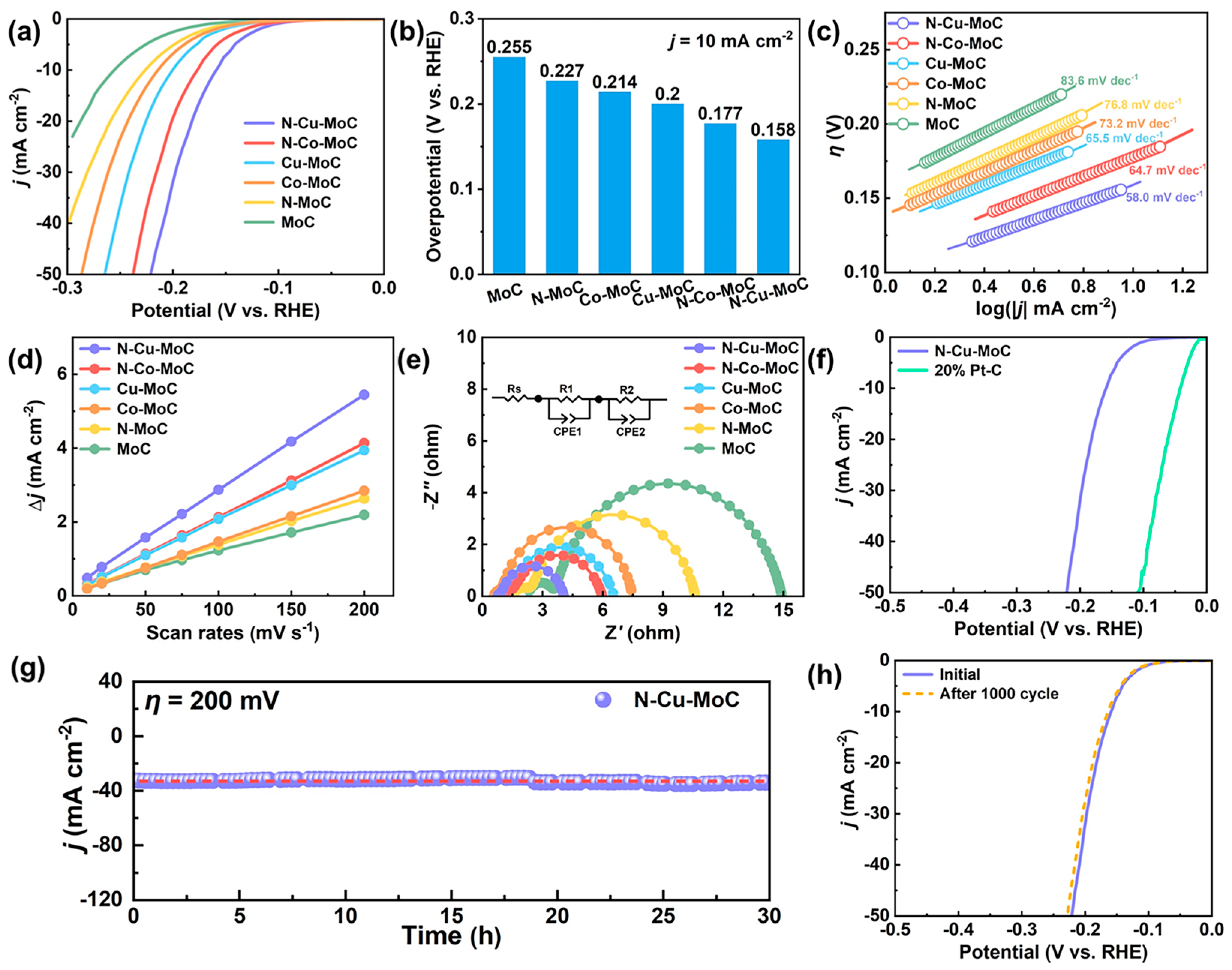
Table S3 (Supporting Information) provides a summary of all the HER performances in alkaline electrolytes. As depicted in Figure 5a,b, the doped system significantly enhanced HER activity compared to pure MoC. The N−Cu−MoC catalyst exhibited excellent HER performance, achieving a low overpotential of 158 mV and 222 mV to attain current densities of 10 mA cm−2 and 50 mA cm−2, respectively. These values were much lower than those of MoC (255 mV and 339 mV), N−MoC (227 mV and 315 mV), Co−MoC (214 mV and 287 mV), Cu−MoC (200 mV and 265 mV), and N−Co−MoC (178 mV and 238 mV). The Tafel slope was calculated using the linear region of the Tafel diagram and is commonly used to investigate electrocatalytic kinetics (Figure 5c). The kinetic process in alkaline HER usually consists of two steps: electrochemical adsorption, i.e., H2O + e− → Hads + OH− (Volmer reaction, 118.2 mV dec−1); electrochemical desorption H2O + e− + Hads → H2 + OH− (Heyrovsky reaction, 39.4 mV dec−1), or chemical desorption Hads + Hads → H2 (Tafel reaction, 29.6 mV dec−1). The calculated Tafel slope of the prepared catalysts was between 39.4 and 118.2 mV dec−1, indicating that the catalytic mechanism of HER obeyed a Volmer–Heyrovsky mechanism [57]. Furthermore, the Tafel slope of N−Cu−MoC (58 mV dec−1) was significantly lower than that of MoC (83.6 mV dec−1), N−MoC (76.8 mV dec−1), Co−MoC (73.2 mV dec−1), Cu−MoC (65.5 mV dec−1), and N−Co−MoC (64.7 mV dec−1), confirming the improved Heyrovsky step in hydrolysis kinetics. Compared with Cu (or Co) doping or N doping alone, the Tafel slope of the N−Cu (or Co) dual−doping system could effectively improve the desorption ability of Hads by decreasing the Tafel slope significantly. Table S4 (Supporting Information) presents the comparison of the HER performance of N−Cu−MoC with other reported electrocatalysts in 1 M KOH, which indicates the excellent HER performance of N−Cu−MoC [58,59,60,61,62,63,64,65,66,67,68,69,70,71,72,73,74,75]. To further explore the intrinsic properties of the as−prepared catalysts, the exchange current density (j0) was calculated by extrapolating the linear part of the Tafel plots. The value of j0 reflected the rate of conversion of the substance at electrochemical equilibrium, so a larger j0 value means better catalytic performance. The obtained j0 values for MoC, N−MoC, Co−MoC, Cu−MoC, N−Co−MoC, and N−Cu−MoC were 1.20 × 10⁻² mA cm−2, 1.29 × 10⁻² mA cm−2, 1.31 × 10⁻² mA cm−2, 1.45 × 10⁻² mA cm−2, 1.80 × 10⁻² mA cm−2, and 1.85 × 10⁻² mA cm−2, respectively. From Table S3 (Supporting Information), it can be seen that the variation pattern of j0 was consistent with the activity variation pattern of the LSV curve. The highest exchange current density of N−Cu−MoC suggested that metal–nitrogen dual−doped systems can boost the intrinsic electron transfer capability of MoC for HER catalysis. Combining the above XPS analysis, the electronic structure of Mo atoms on the surface of N−Cu−MoC was optimized due to the copper–nitrogen dual−doping effect, increasing the electron cloud density of its Mo atoms and promoting the hydrogen adsorption process after the dissociation of water molecules, thus improving the HER performance.
To gain a deeper understanding of the enhanced HER activity, the electrochemical active surface area (ECSA) of the samples was determined by measuring the non-faradaic electrical double−layer capacitance (Cdl) derived from the cyclic voltammetry (CV) measurements at different scan rates. The CVs of the as-prepared samples with varying scan rates were recorded at the Faradic silence potential, as shown in Figure S11 (Supporting Information). In Figure 5d, the Cdl of N−Cu−MoC is 26.1 mF cm−2, which is higher than that of MoC (10.5 mF cm−2), N−MoC (12.6 mF cm−2), Co−MoC (14.0 mF cm−2), Cu−MoC (19.2 mF cm−2), and N−Co−MoC (20.1 mF cm−2). This indicates that the dual-doped N−Cu−MoC system could significantly expand the electrochemically active region, providing more catalytically active sites that contribute to the HER performance. To further understand the electrode kinetics during the HER process, the electrochemical impedance spectroscopy (EIS) measurement was carried out at −200 mV vs. RHE from 100 kHz to 0.01 Hz. Then, the EIS results were fitted using the simplified equivalent circuit shown in Figure 5e to obtain the charge transfer resistance (Rct). It could be seen that in the low−frequency region MoC, N−MoC, Co−MoC, Cu−MoC, N−Cu−MoC, and N−Cu−MoC all showed a distinct capacitive arc, which is usually considered to be generated by the two hydrogen precipitation steps of Volmer and Heyrovsky, i.e., the charge transfer process. Evidently, the Rct value of N−Cu−MoC (3.30 Ω) was smaller than that of MoC (11.35 Ω), N−MoC (8.37 Ω), Co−MoC (6.57 Ω), Cu−MoC (5.44 Ω), and N−Co−MoC (4.84 Ω), indicating that N−Cu−MoC had a faster charge transfer ability during hydrogen precipitation. Therefore, the N−Cu dual−doping system could effectively modify the MoC surface and improve the charge transfer process. To study the stability of the N−Cu−MoC structure, 1000 cycles of continuous cyclic voltammetry tests were performed. As shown in Figure 5h, the LSV curves before and after the test did not change significantly, indicating that N−Cu−MoC has good stability during HER. The stability of the N−Cu−MoC catalyst was also evaluated at a constant voltage of 200 mV, and it maintained its activity for up to 30 h, surpassing the stability of the commercial 20% Pt/C catalyst (as shown in Figure 5g and Figure S12). It can be found that, although the activity of N−Cu−MoC was lower than that of commercial Pt/C catalyst (Figure 5f), its stability was much higher than that of 20% Pt/C catalyst (Figure 5f–h). To evaluate the intrinsic activity of the individual active site, js−normalized and jECSA−normalized polarization curves were also calculated (Figure S13, Supporting Information). One can see that the N−Cu−MoC also exhibits the largest jECSA and js values compared with the others, confirming its highly intrinsic activity.
3. Materials and Methods
3.1. Materials Synthesis
Preparation of N−MoOx precursor: Mo−NH2 precursor (N−MoOx) was synthesized using the organic–inorganic hybrid method. Firstly, a certain amount of ammonium molybdate tetrahydrate (2.48 g, (NH4)6Mo7O24·4H2O; ≥99%, Sigma−Aldrich, Guangzhou, China) was dissolved in 40 mL deionized water containing m−Phenylenediamine (C6H4(NH2)2; >99%, Sigma−Aldrich, Guangzhou, China) with Mo/NH2 molar ratio of 1:3, stirring evenly. Then, 1 M HCl was added to adjust the pH value to 2.5~3. The resulting mixture was stirred in an oil bath at 65 °C until dry. The solid product was dried in a vacuum oven at 65 °C overnight after being washed with ethanol and water.
Preparation of N−MoC electrocatalysts: N−MoC was prepared via the temperature−programmed carburization of the obtained N−MoOx in a fixed−bed quartz microreactor with an inner diameter of 8 mm and kept under Ar flow (50 mL min−1) to remove air for 4 h. Then, the sample was calcinated at 700 °C for 5 h with a ramping rate of 2 °C min−1 from room temperature (RT). After that, the obtained powder was quenched to RT in a flow of Ar (50 cm3 min−1) and passivated at RT in a flow of 1% O2/Ar (5 cm3 min−1) for 12 h.
Preparation of N−M (M = Cu or Co)−MoOx precursor: Firstly, the copper nitrate trihydrate (Cu(NO3)2·3H2O; ≥99%, Aladdin, Guangzhou, China) or cobalt nitrate hexahydrate (Co(NO3)2·6H2O; ≥99%, Aladdin, Guangzhou, China) corresponding to 3% mass fraction of Cu or Co (molar ratio of M/(M + Mo) = 1:18, M = Cu or Co) in the catalyst was dissolved in 10 mL deionized water and then added to 30 mL of the above mixture solution with a Mo/NH2 molar ratio of 1:3. Then, 1M HCl was added to adjust the pH value to 2.5~3. The resulting mixture was stirred in an oil bath at 65 °C until dry. The solid product was dried in a vacuum oven at 65 °C overnight after being washed with ethanol and water.
Preparation of N−M (M = Cu or Co)−MoC electrocatalysts: N−M−MoC was prepared via the temperature−programmed carburization of the obtained N−M−MoOx in a fixed−bed quartz microreactor with an inner diameter of 8 mm and kept under Ar flow (50 mL min−1) to remove air for 4 h and then calcinated at 700 °C for 5 h with a ramping rate of 2 °C min−1 from room temperature (RT). The obtained powder was quenched to RT in a flow of Ar (50 cm3 min−1) and passivated at RT in a flow of 1% O2/Ar (5 cm3 min−1) for 12 h.
Preparation of M−MoC (M = Cu or Co) and MoC electrocatalysts: In brief, the as−prepared N−MoC and N−M−MoC catalyst powders were filled into the above microreactor and subjected to a nitrogen removal process under 20% CH4/H2 atmosphere with a flow rate of 150 cm3 min−1 at 700 °C with a ramping rate of 10 °C min−1 and held at the final temperature for 2 h. The resulting black powder was then quenched to RT in the 20% CH4/H2 flow and finally passivated at RT in 1% O2/Ar for 12 h. These samples were denoted as M−MoC (M = Cu or Co) and MoC.
3.2. Catalyst Characterizations
X-ray diffraction (XRD) patterns were recorded on a Bruker D8 ADVANCE diffractometer using Cu Kα radiation (λ = 1.5406 Å). Phase identification was achieved by comparison of the obtained patterns with those of the Joint Committee on Powder Diffraction Standards (JCPDS). Brunauer–Emmett–Teller (BET) surface area was measured through N2 adsorption isotherms recorded at 77 K, using a Micromeritics Tristar II Plus automatic absorption instrument. Sample nanostructures and morphologies were characterized using transmission electron microscopy (TEM) (Talos F200S, FEI) at 200 kV and scanning electron microscopy (SEM) (SU8220, Hitachi) at 15 kV. Surface chemical states were determined by XPS (Thermo Fisher Escalab 250Xi) using the C 1s (284.8 eV) peak as a reference and Al Kα radiation as a photon source. The binding energies of Mo 3d, Co 2p, Cu 2p, and C 1s were analyzed by using the Shirley baseline correction.
3.3. Electrochemical Measurements
Firstly, 4 mg catalyst powder was dispersed in 1 mL ethanol solvents. Then, the solution was mixed with 25 µL 5 wt% Nafion solution and sonicated for at least 30 min. Finally, 5 µL catalyst ink was loaded on a glassy carbon electrode (GCE: diameter = 5 mm) at a catalyst loading of about 0.49 mg cm−2. The obtained electrocatalyst was tested in 1M KOH (pH = 14) solutions using a typical three-electrode setup. Hg/HgO electrode and graphite rod were used as the reference and counter electrodes, respectively. The LSV (linear sweep voltammetry) curves were maintained at a scan rate of 2 mV s−1 with GAMRY Interface1010 workstation. All potentials were referenced to a reversible hydrogen electrode (RHE): ERHE = EHg/HgO + (0.098 + 0.059 pH) V. Long-time stability was measured using a chronoamperometry method at a constant voltage of 200 mV for 30 h and a continuous CV for 1000 cycles. EIS was performed at η = 200 mV overpotential with a frequency range from 0.01 to 100,000 Hz.
Electrochemical Active Surface Area () Calculation: The ECSA was calculated using the double-layer capacitances (Cdl), in which the specific capacitance for a flat catalyst surface was supposed to be ≈40 μF cm−2, and the was obtained using Equation (1):
Specific Activity Calculation: The specific activity (, mA cm−2 cat.) calculation was based on Equation (2), where j is the current density (mA cm−2), A is the electrode area (cm2), the BET surface of the obtained catalysts, and the is the loading amount on the GCE.
4. Conclusions
In this study, we successfully synthesized a copper-nitrogen dual-doped molybdenum carbide (N−Cu−MoC) electrocatalyst through a simple organic-inorganic hybridization method. Our results demonstrate that this material exhibits remarkable hydrogen evolution reaction (HER) catalytic activity and stability, which can be attributed to its unique layer−stacked sheet structure and the synergistic modulation of the electronic structure of the molybdenum carbide surface via copper-nitrogen dual doping. The N−Cu−MoC electrocatalyst only required 158 mV at a −10 mA cm−2 current density and maintains stability for a long time. Both SEM and TEM images revealed that the thin lamellar structure offers more channels and area for the mass transfer of the reaction. Furthermore, XPS analysis demonstrated that both Cu and N doping alone can enrich the electrons around the Mo atoms, thereby effectively reducing the strong Mo−H banding energy according to the d-band center theory. However, the dual doping of both can synergistically regulate the electron cloud density around Mo, effectively improving the HER performance. These findings suggest that metal-nonmetal dual doping could provide a novel approach for designing high−performance metal-carbide catalysts for HER evolution.
Supplementary Materials
The following supporting information can be downloaded at: https://www.mdpi.com/article/10.3390/catal13060931/s1, Figure S1: Standard XRD patterns of MoO2 (a); MoO3 (b); MoC (c); metallic Mo (d); metallic Co (e); and metallic Cu (f); Figure S2: Comparison of pore size, pore volume and specific surface area of N−Co−MoC, Co−MoC, N−Cu−MoC, and Cu−MoC; Figure S3: Morphology of N−MoC (a) TEM image and N−MoC particle size distribution; (b) corresponding Crystal lattice stripe pattern of the (a); (c) TEM image of N−MoC; Figure S4: Morphology of MoC (a) TEM image and MoC particle size distribution; (b) corresponding crystal lattice stripe pattern of the (a); (c) TEM image of MoC; Figure S5: Morphology of N−Co−MoC (a) TEM image and N−Co−MoC particle size distribution; (b) corresponding crystal lattice stripe pattern of the (a); (c) TEM image of N−Co−MoC; Figure S6: Morphology of Co−MoC (a) TEM image and Co−MoC particle size distribution; (b) corresponding crystal lattice stripe pattern of the (a); (c) TEM image of Co−MoC; Figure S7: Morphology of Cu−MoC (a) TEM image and Cu−MoC particle size distribution; (b) corresponding crystal lattice stripe pattern of the (a); (c) TEM image of Cu−MoC; Figure S8: SEM images of N−Cu−MoC; Figure S9: Mo 3d high−resolution XPS spectra of Co−MoC (a) and N−Co−MoC (b); (c) Co 2p high−resolution XPS spectra of Co−MoC and N−Co−MoC; (d) N 1s high resolution XPS spectra of N−Co−MoC; Figure S10: C 1s High resolution XPS spectra of N−MoC (a), MoC (b), N−Cu−MoC (c), Cu−MoC (d), N−Co−MoC (e), and Co−MoC (f); Figure S11: Cyclic voltammograms of (a) MoC; (b) N−MoC; (c) Co−MoC; (d) N−Co−MoC; (c) Cu−MoC; and (d) N−Cu−MoC with various scan rates in 1 M KOH solution; Figure S12. The stabile operation of 20% Pt/C in 1M KOH electrolyte; Figure S13. Specific activity (a) js−normalized polarization curves (calculated based on BET surface area); (b) jECSA−normalized polarization curves (calculated based on ECSA). The stabile operation of 20% Pt/C in 1M KOH electrolyte; Table S1: Summary of BET specific surface area, pore volume, and pore size of MoC, N−MoC, Cu−MoC, Co−MoC, N−Co−MoC, and N−Cu−MoC; Table S2: Mo binding energy and Mo−N bonding energy of MoC, N−MoC, Co−MoC, N−Co−MoC, Cu−MoC, and N−Cu−MoC, and the percentage of surface composition of surface Mo2+ and Mo−N Species; Table S3: Summary of HER activity of MoC, N−MoC, Cu−MoC, Co−MoC, N−Co−MoC, and N−Cu−MoC in 1 M KOH; Table S4: Comparison of HER performances of N−Cu−MoC with other electrocatalysts in 1 M KOH.
Author Contributions
Conceptualization, Y.M. and L.X.; methodology, Y.M.; validation, Y.M., L.X. and T.W.; formal analysis, J.W. and L.H.; investigation, Y.M.; resources, Y.M.; data curation, L.X.; writing—original draft preparation, Y.M. and L.X.; writing—review and editing, Y.M.; visualization, J.W.; supervision, Y.M. and T.W.; project administration, Y.M.; funding acquisition, Y.M. and T.W. All authors have read and agreed to the published version of the manuscript.
Funding
This research was funded by the National Natural Science Foundation of China (Grants No. 51701046), the Scientific Research Foundation of Shanwei Institute of Technology (No. 2020KYQD–02), and the Special Foundation for Key Fields of Colleges and Universities in Guangdong Province (2021ZDZX4094).
Data Availability Statement
Data available from the author.
Acknowledgments
The authors gratefully acknowledge the support of the Guangdong University of Technology and the Shanwei Institute of Technology.
Conflicts of Interest
The authors declare no conflict of interest.
References
- Yu, Z.; Duan, Y.; Feng, X.; Yu, X.; Gao, M.; Yu, S. Clean and affordable hydrogen fuel from alkaline water splitting: Past, recent progress, and future prospects. Adv. Mater. 2021, 33, 2007100. [Google Scholar] [CrossRef] [PubMed]
- Li, Y.; Tan, X.; Tan, H.; Ren, H.; Chen, S.; Yang, W.; Smith, S.; Zhao, C. Phosphine vapor−assisted construction of heterostructured Ni2P/NiTe2 catalysts for efficient hydrogen evolution. Energy Environ. Sci. 2020, 13, 1799–1807. [Google Scholar] [CrossRef]
- Li, R.; Wang, D. Understanding the structure−performance relationship of active sites at atomic scale. Nano Res. 2022, 15, 6888–6923. [Google Scholar] [CrossRef]
- Wismann, S.; Engbaek, J.; Vendelbo, S.; Bendixen, F.; Eriksen, W.; Aasberg−Petersen, K.; Frandsen, C.; Chorkendorff, I.; Mortensen, P. Electrified methane reforming: A compact approach to greener industrial hydrogen production. Science 2019, 364, 756–759. [Google Scholar] [CrossRef]
- Herdem, M.; Sinaki, M.; Farhad, S.; Hamdullahpur, F. An overview of the methanol reforming process: Comparison of fuels, catalysts, reformers, and systems. A review. Int. J. Energy Res. 2019, 43, 5076–5105. [Google Scholar] [CrossRef]
- Yang, Y.; Qian, Y.; Li, H.; Zhang, Z.; Mu, Y.; Do, D.; Zhou, B.; Dong, J.; Yan, W.; Qin, Y.; et al. O−coordinated W−Mo dual−atom catalyst for pH−universal electrocatalytic hydrogen evolution. Sci. Adv. 2020, 6, eaba6586. [Google Scholar] [CrossRef]
- Yang, J.; Li, W.H.; Tan, S.; Xu, K.; Wang, Y.; Wang, D.; Li, Y. The electronic metal−support interaction directing the design of single atomic site catalysts: Achieving high efficiency towards hydrogen evolution. Angew. Chem. Int. Ed. 2021, 60, 19085–19091. [Google Scholar] [CrossRef]
- Chen, M.; Liu, J.; Kitiphatpiboon, N.; Li, X.; Wang, J.; Hao, X.; Abudula, A.; Ma, Y.; Guan, G. Zn−VOx−Co nanosheets with amorphous/crystalline heterostructure for highly efficient hydrogen evolution reaction. Chem. Eng. J. 2022, 432, 134329. [Google Scholar] [CrossRef]
- Chen, M.; Su, Q.; Kitiphatpiboon, N.; Zhang, J.; Feng, C.; Li, S.; Zhao, Q.; Abudula, A.; Ma, Y.; Guan, G. Heterojunction engineering of Ni3S2/NiS nanowire for electrochemical hydrogen evolution. Fuel 2023, 331, 125794. [Google Scholar] [CrossRef]
- Chen, M.; Kitiphatpiboon, N.; Feng, C.; Zhao, Q.; Abudula, A.; Ma, Y.; Yan, K.; Guan, G. Tuning octahedron sites in MnFe2O4 spinel by boron doping for highly efficient seawater splitting. Appl. Catal. B 2023, 330, 122577. [Google Scholar] [CrossRef]
- Zhuang, L.; Jia, Y.; Liu, H.; Li, Z.; Li, M.; Zhang, L.; Wang, X.; Yang, D.; Zhu, Z.; Yao, X. Sulfur−modified oxygen vacancies in iron−cobalt oxide nanosheets: Enabling extremely high activity of the oxygen evolution reaction to achieve the industrial water splitting benchmark. Angew. Chem. Int. Ed. 2020, 59, 14664–14670. [Google Scholar] [CrossRef] [PubMed]
- Yang, H.; Driess, M.; Menezes, P. Self−supported electrocatalysts for practical water electrolysis. Adv. Energy Mater. 2021, 11, 2102074. [Google Scholar] [CrossRef]
- Chen, M.; Kitiphatpiboon, N.; Feng, C.; Abudula, A.; Ma, Y.; Guan, G. Recent progress in transition−metal−oxide−based electrocatalysts for the oxygen evolution reaction in natural seawater splitting: A critical review. eScience 2023, 3, 100111. [Google Scholar] [CrossRef]
- You, B.; Sun, Y. Innovative strategies for electrocatalytic water splitting. Acc. Chem. Res. 2018, 51, 1571–1580. [Google Scholar] [CrossRef]
- Sun, H.; Yan, Z.; Liu, F.; Xu, W.; Cheng, F.; Chen, J. Self−supported transition−metal−based electrocatalysts for hydrogen and oxygen evolution. Adv. Mater. 2020, 32, e1806326. [Google Scholar] [CrossRef]
- Xu, K.; Sun, Y.; Li, X.; Zhao, Z.; Zhang, Y.; Li, C.; Fan, H. Fluorine−induced dual defects in cobalt phosphide nanosheets enhance hydrogen evolution reaction activity. ACS Mater. Lett. 2020, 2, 736–743. [Google Scholar] [CrossRef]
- Wan, C.; Regmi, Y.; Leonard, B. Multiple phases of molybdenum carbide as electrocatalysts for the hydrogen evolution reaction. Angew. Chem. Int. Ed. 2014, 53, 6407–6410. [Google Scholar] [CrossRef]
- Tian, D.; Denny, S.; Li, K.; Wang, H.; Kattel, S.; Chen, J. Density functional theory studies of transition metal carbides and nitrides as electrocatalysts. Chem. Soc. Rev. 2021, 50, 12338–12376. [Google Scholar] [CrossRef]
- Lin, F.; Qin, H.; Wang, T.; Yang, L.; Cao, X.; Jiao, L. Few−layered MoN−MnO heterostructures with interfacial−O synergistic active centers boosting electrocatalytic hydrogen evolution. J. Mater. Chem. A 2021, 9, 8325–8331. [Google Scholar] [CrossRef]
- Zhang, L.; Xiao, W.; Zhang, Y.; Han, F.; Yang, X. Nanocarbon encapsulating Ni−doped MoP/graphene composites for highly improved electrocatalytic hydrogen evolution reaction. Compos. Commun. 2021, 26, 100792. [Google Scholar] [CrossRef]
- Vrubel, H.; Hu, X. Molybdenum boride and carbide catalyze hydrogen evolution in both acidic and basic solutions. Angew. Chem. Int. Ed. 2012, 51, 12703–12706. [Google Scholar] [CrossRef] [PubMed]
- Ma, Y.; Chen, M.; Geng, H.; Dong, H.; Wu, P.; Li, X.; Guan, G.; Wang, T. Synergistically tuning electronic structure of porous β-Mo2C spheres by Co doping and Mo−vacancies defect engineering for optimizing hydrogen evolution reaction activity. Adv. Funct. Mater. 2020, 30, 2000561. [Google Scholar] [CrossRef]
- Zhao, G.; Rui, K.; Dou, S.; Sun, W. Heterostructures for electrochemical hydrogen evolution reaction: A review. Adv. Funct. Mater. 2018, 28, 1803291. [Google Scholar] [CrossRef]
- Ouyang, T.; Ye, Y.; Wu, C.; Xiao, K.; Liu, Z. Heterostructures composed of N−doped carbon nanotubes encapsulating cobalt and beta−Mo2C nanoparticles as bifunctional electrodes for water splitting. Angew. Chem. Int. Ed. 2019, 58, 4923–4928. [Google Scholar] [CrossRef] [PubMed]
- Song, H.; Sung, M.; Yoon, H.; Ju, B.; Kim, D. Ultrafine alpha−Phase molybdenum carbide decorated with platinum nanoparticles for efficient hydrogen production in acidic and alkaline media. Adv. Sci. 2019, 6, 1802135. [Google Scholar] [CrossRef] [PubMed]
- Ma, R.; Zhou, Y.; Chen, Y.; Li, P.; Liu, Q.; Wang, J. Ultrafine molybdenum carbide nanoparticles composited with carbon as a highly active hydrogen−evolution electrocatalyst. Angew. Chem. Int. Ed. 2015, 54, 14723–14727. [Google Scholar] [CrossRef]
- Wang, Y.; Hong, W.; Jian, C.; He, X.; Cai, Q.; Liu, W. The intrinsic hydrogen evolution performance of 2D molybdenum carbide. J. Mater. Chem. A 2020, 8, 24204–24211. [Google Scholar] [CrossRef]
- Anjum, M.; Lee, M.; Lee, J. BCN network−encapsulated multiple phases of molybdenum carbide for efficient hydrogen evolution reactions in acidic and alkaline media. J. Mater. Chem. A 2017, 5, 13122–13129. [Google Scholar] [CrossRef]
- Huang, Y.; Gong, Q.; Song, X.; Feng, K.; Nie, K.; Zhao, F.; Wang, Y.; Zeng, M.; Zhong, J.; Li, Y. Mo2C nanoparticles dispersed on hierarchical carbon microflowers for efficient electrocatalytic hydrogen evolution. ACS Nano 2016, 10, 11337–11343. [Google Scholar] [CrossRef]
- Tang, T.; Wang, Z.; Guan, J. A review of defect engineering in two−dimensional materials for electrocatalytic hydrogen evolution reaction. Chin. J. Catal. 2022, 43, 636–678. [Google Scholar] [CrossRef]
- Zubair, M.; Ul Hassan, M.; Mehran, M.; Baig, M.; Hussain, S.; Shahzad, F. 2D MXenes and their heterostructures for HER, OER and overall water splitting: A review. Int. J. Hydrogen Energy 2022, 47, 2794–2818. [Google Scholar] [CrossRef]
- Liu, B.; Liu, L.; Du, Q.; Zhao, R.; Du, J. Engineering micro/nanostructures of Mo2C/porous nanocarbon for enhanced hydrogen production. New J. Chem. 2023, 47, 3417–3424. [Google Scholar] [CrossRef]
- Zhao, Y.; Kamiya, K.; Hashimoto, K.; Nakanishi, S. Hydrogen evolution by tungsten carbonitride nanoelectrocatalysts synthesized by the formation of a tungsten acid/polymer hybrid in situ. Angew. Chem. Int. Ed. 2013, 52, 13638–13641. [Google Scholar] [CrossRef] [PubMed]
- Han, N.; Yang, K.; Lu, Z.; Li, Y.; Xu, W.; Gao, T.; Cai, Z.; Zhang, Y.; Batista, V.; Liu, W.; et al. Nitrogen−doped tungsten carbide nanoarray as an efficient bifunctional electrocatalyst for water splitting in acid. Nat. Commun. 2018, 9, 924. [Google Scholar] [CrossRef] [PubMed]
- Liu, Y.; Yu, G.; Li, G.; Sun, Y.; Asefa, T.; Chen, W.; Zou, X. Coupling Mo2C with nitrogen−rich nanocarbon leads to efficient hydrogen−evolution electrocatalytic sites. Angew. Chem. Int. Ed. 2015, 54, 10752–10757. [Google Scholar] [CrossRef] [PubMed]
- Chen, Y.; Zhang, Y.; Jiang, W.; Zhang, X.; Dai, Z.; Wan, L.; Hu, J. Pomegranate—like N,P—doped Mo2C@C nanospheres as highly active electrocatalysts for alkaline hydrogen evolution. ACS Nano 2016, 10, 8851–8860. [Google Scholar] [CrossRef] [PubMed]
- Jia, J.; Xiong, T.; Zhao, L.; Wang, F.; Liu, H.; Hu, R.; Zhou, J.; Zhou, W.; Chen, S. Ultrathin N−doped Mo2C nanosheets with exposed active sites as efficient electrocatalyst for hydrogen evolution reactions. ACS Nano 2017, 11, 12509–12518. [Google Scholar] [CrossRef] [PubMed]
- Men, Y.; Li, P.; Yang, F.; Cheng, G.; Chen, S.; Luo, W. Nitrogen−doped CoP as robust electrocatalyst for high−efficiency pH universal hydrogen evolution reaction. Appl. Catal. B 2019, 253, 21–27. [Google Scholar] [CrossRef]
- Yan, J.; Kong, L.; Ji, Y.; Li, Y.; White, J.; Liu, S.; Han, X.; Lee, S.; Ma, T. Air−stable phosphorus−doped molybdenum nitride for enhanced electrocatalytic hydrogen evolution. Commun. Chem. 2018, 1, 95. [Google Scholar] [CrossRef]
- Li, F.; Han, G.; Noh, H.; Jeon, J.; Ahmad, I.; Chen, S.; Yang, C.; Bu, Y.; Fu, Z.; Lu, Y.; et al. Balancing hydrogen adsorption/desorption by orbital modulation for efficient hydrogen evolution catalysis. Nat. Commun. 2019, 10, 4060. [Google Scholar] [CrossRef]
- Fan, H.; Yu, H.; Zhang, Y.; Zheng, Y.; Luo, Y.; Dai, Z.; Li, B.; Zong, Y.; Yan, Q. Fe−doped Ni3C nanodots in N−doped carbon nanosheets for efficient hydrogen−evolution and oxygen−evolution electrocatalysis. Angew. Chem. Int. Ed. 2017, 56, 12566–12570. [Google Scholar] [CrossRef] [PubMed]
- Yu, F.; Gao, Y.; Lang, Z.; Ma, Y.; Yin, L.; Du, J.; Tan, H.; Wang, Y.; Li, Y. Electrocatalytic performance of ultrasmall Mo2C affected by different transition metal dopants in hydrogen evolution reaction. Nanoscale 2018, 10, 6080–6087. [Google Scholar] [CrossRef] [PubMed]
- Xu, X.; Nosheen, F.; Wang, X. Ni−decorated molybdenum carbide hollow structure derived from carbon−coated metal−organic framework for electrocatalytic hydrogen evolution reaction. Chem. Mater. 2016, 28, 6313–6320. [Google Scholar] [CrossRef]
- Lin, H.; Liu, N.; Shi, Z.; Guo, Y.; Tang, Y.; Gao, Q. Cobalt−Doping in molybdenum−carbide nanowires toward efficient electrocatalytic hydrogen evolution. Adv. Funct. Mater. 2016, 26, 5590–5598. [Google Scholar] [CrossRef]
- Ma, Y.; Liu, J.; Chen, M.; Yang, Q.; Chen, H.; Guan, G.; Qin, Y.; Wang, T. Selective hydrogenation of naphthalene to decalin over surface-engineered α-MoC based on synergy between Pd doping and Mo vacancy generation. Adv. Funct. Mater. 2022, 32, 2112435. [Google Scholar] [CrossRef]
- Shi, J.; Hu, L.; Liu, J.; Chen, M.; Li, C.; Guan, G.; Ma, Y.; Wang, T. Phase−transition engineering induced lattice contraction of the molybdenum carbide surface for highly efficient hydrogen evolution reaction. J. Mater. Chem. A 2022, 10, 11414–11425. [Google Scholar] [CrossRef]
- Khan, K.; Tareen, A.; Aslam, M.; Zhang, Y.; Wang, R.; Ouyang, Z.; Gou, Z.; Zhang, H. Recent advances in two−dimensional materials and their nanocomposites in sustainable energy conversion applications. Nanoscale 2019, 11, 21622–21678. [Google Scholar] [CrossRef]
- Liu, W.; Wang, X.; Wang, F.; Du, K.; Zhang, Z.; Guo, Y.; Yin, H.; Wang, D. A durable and pH−universal self−standing MoC−Mo2C heterojunction electrode for efficient hydrogen evolution reaction. Nat. Commun. 2021, 12, 6776. [Google Scholar] [CrossRef]
- Li, H.; Hu, M.; Zhang, L.; Huo, L.; Jing, P.; Liu, B.; Gao, R.; Zhang, J.; Liu, B. Hybridization of bimetallic molybdenum−tungsten carbide with nitrogen−doped carbon: A rational design of super active porous composite nanowires with tailored electronic structure for boosting hydrogen evolution catalysis. Adv. Funct. Mater. 2020, 30, 2003198. [Google Scholar] [CrossRef]
- Reynard, D.; Nagar, B.; Girault, H. Photonic flash synthesis of Mo2C/graphene electrocatalyst for the hydrogen evolution reaction. ACS Catal. 2021, 11, 5865–5872. [Google Scholar] [CrossRef]
- Zhang, P.; Liu, Y.; Liang, T.; Ang, E.; Zhang, X.; Ma, F.; Dai, Z. Nitrogen−doped carbon wrapped Co−Mo2C dual Mott−Schottky nanosheets with large porosity for efficient water electrolysis. Appl. Catal. B 2021, 284, 119738. [Google Scholar] [CrossRef]
- Li, M.; Zhu, Y.; Wang, H.; Wang, C.; Pinna, N.; Lu, X. Ni Strongly coupled with Mo2C encapsulated in nitrogen−doped carbon nanofibers as robust bifunctional catalyst for overall water splitting. Adv. Energy Mater. 2019, 9, 1803185. [Google Scholar] [CrossRef]
- Kim, S.; Choi, C.; Hwang, J.; Park, J.; Jeong, J.; Jun, H.; Lee, S.; Kim, S.; Jang, J.; Jung, Y.; et al. Interaction Mediator Assisted Synthesis of Mesoporous Molybdenum Carbide: Mo−valence state adjustment for optimizing hydrogen evolution. ACS Nano 2020, 14, 4988–4999. [Google Scholar] [CrossRef] [PubMed]
- Liu, Z.; Zhou, S.; Xue, S.; Guo, Z.; Li, J.; Qu, K.; Cai, W. Heterointerface−rich Mo2C/MoO2 porous nanorod enables superior alkaline hydrogen evolution. Chem. Eng. J. 2021, 421, 127807. [Google Scholar] [CrossRef]
- Yao, Q.; Huang, B.; Zhang, N.; Sun, M.; Shao, Q.; Huang, X. Channel−rich RuCu nanosheets for pH−universal overall water splitting electrocatalysis. Angew. Chem. Int. Ed. 2019, 58, 13983–13988. [Google Scholar] [CrossRef] [PubMed]
- Zhao, D.; Sun, K.; Cheong, W.; Zheng, L.; Zhang, C.; Liu, S.; Cao, X.; Wu, K.; Pan, Y.; Zhuang, Z.; et al. Synergistically interactive pyridinic−N−MoP sites: Identified active centers for enhanced hydrogen evolution in alkaline solution. Angew. Chem. Int. Ed. 2020, 59, 8982–8990. [Google Scholar] [CrossRef] [PubMed]
- Chen, Z.; Wu, R.; Liu, Y.; Ha, Y.; Guo, Y.; Sun, D.; Liu, M.; Fang, F. Ultrafine Co nanoparticles encapsulated in carbon−nanotubes−grafted graphene sheets as advanced electrocatalysts for the hydrogen evolution reaction. Adv. Mater. 2018, 30, e1802011. [Google Scholar] [CrossRef]
- Cui, S.; Li, M.; Bo, X. Co/Mo2C composites for efficient hydrogen and oxygen evolution reaction. Int. J. Hydrogen Energ. 2020, 45, 21221–21231. [Google Scholar] [CrossRef]
- Ai, L.; Su, J.; Wang, M.; Jiang, J. Bamboo-structured nitrogen-doped carbon nanotube coencapsulating cobalt and molybdenum carbide nanoparticles: An efficient bifunctional electrocatalyst for overall water splitting. ACS Sustain. Chem. Eng. 2018, 6, 9912–9920. [Google Scholar] [CrossRef]
- Ji, M.; Niu, S.; Du, Y.; Song, B.; Xu, P. Anion-induced size selection of β-Mo2C supported on nitrogen-doped carbon nanotubes for electrocatalytic hydrogen evolution. ACS Sustain. Chem. Eng. 2018, 6, 11922–11929. [Google Scholar] [CrossRef]
- Wu, Z.; Hu, B.; Wu, P.; Liang, H.; Yu, Z.; Lin, Y.; Zheng, Y.; Li, Z.; Yu, S. Mo2C nanoparticles embedded within bacterial cellulose-derived 3D N-doped carbon nanofiber networks for efficient hydrogen evolution. NPG Asia Mater. 2016, 8, e288. [Google Scholar] [CrossRef]
- Huang, H.; Yu, C.; Huang, H.; Guo, W.; Zhang, M.; Han, X.; Wei, Q.; Cui, S.; Tan, X.; Qiu, J. Microwave-assisted ultrafast synthesis of molybdenum carbide nanoparticles grown on carbon matrix for efficient hydrogen evolution reaction. Small Methods 2019, 3, 1900259. [Google Scholar] [CrossRef]
- Yu, Z.; Duan, Y.; Gao, M.; Lang, C.; Zheng, Y.; Yu, S. A one-dimensional porous carbon-supported Ni/Mo2C dual catalyst for efficient water splitting. Chem. Sci. 2017, 8, 968–973. [Google Scholar] [CrossRef]
- Li, X.; Hu, X.; Wang, X.; Pan, Q.; Liu, L.; Su, Z. A substrate-free Mo2C-based electrocatalyst by facile glucose-blowing for efficient hydrogen production. New J. Chem. 2019, 43, 18970–18974. [Google Scholar] [CrossRef]
- Li, S.; Dong, B.; Yuan, y.; Xu, P.; Xu, P. Synthesis of porous Mo2C/nitrogen-doped carbon nanocomposites for efficient hydrogen evolution reaction. Chemistryselect 2020, 5, 14307–14311. [Google Scholar] [CrossRef]
- Wang, D.; Guo, T.; Wu, Z. Hierarchical Mo2C/C scaffolds organized by nanosheets as highly efficient electrocatalysts for hydrogen production. ACS Sustain. Chem. Eng. 2018, 6, 13995–14003. [Google Scholar] [CrossRef]
- Wang, Q.; Mi, F.; Li, J.; Wu, Y.; Zhou, X.; Ma, G.; Ren, S. Tungsten doping generated Mo2C-MoC heterostructure to improve HER performance in alkaline solution. Electrochimica Acta 2021, 370, 137796. [Google Scholar] [CrossRef]
- Ying, L.; Sun, S.; Liu, W.; Zhu, H.; Zhu, Z.; Liu, A.; Yang, L.; Lu, S.; Duan, F.; Yang, C.; et al. Heterointerface engineering in bimetal alloy/metal carbide for superior hydrogen evolution reaction. Renew. Energ. 2020, 161, 1036–1045. [Google Scholar] [CrossRef]
- Yang, C.; Zhao, R.; Xiang, H.; Wu, J.; Zhong, W.; Li, W.; Zhang, Q.; Yang, N.; Li, X. Ni-activated transition metal carbides for efficient hydrogen evolution in acidic and alkaline solutions. Adv. Energy Mater. 2020, 10, 2002260. [Google Scholar] [CrossRef]
- Li, M.; Wang, H.; Zhu, Y.; Tian, D.; Wang, C.; Lu, X. Mo/Mo2C encapsulated in nitrogen-doped carbon nanofibers as efficiently integrated heterojunction electrocatalysts for hydrogen evolution reaction in wide pH range. Appl. Surf. Sci. 2019, 496, 143672. [Google Scholar] [CrossRef]
- Wang, J.; Wang, W.; Ji, L.; Czioska, S.; Guo, L.; Chen, Z. Highly dispersed Mo2C nanoparticles embedded in ordered mesoporous carbon for efficient hydrogen evolution. ACS Appl. Energ. Mater. 2018, 1, 736–743. [Google Scholar] [CrossRef]
- Wan, J.; Wu, J.; Gao, X.; Li, T.; Hu, Z.; Yu, H.; Huang, L. Structure confined porous Mo2C for efficient hydrogen evolution. Adv. Funct. Mater. 2017, 27, 1703933. [Google Scholar] [CrossRef]
- Ma, L.; Ting, L.; Molinari, V.; Giordano, C.; Yeo, B. Efficient hydrogen evolution reaction catalyzed by molybdenum carbide and molybdenum nitride nanocatalysts synthesized via the urea glass route. J. Mater. Chem. A. 2015, 3, 8361–8368. [Google Scholar] [CrossRef]
- Chang, H.; Zhang, G.; Chou, K. Controllable synthesis of Mo2C with different morphology and application to electrocatalytic hydrogen evolution reaction. Nanotechnology 2021, 33, 105402. [Google Scholar] [CrossRef] [PubMed]
- Wu, Z.; Wang, J.; Liu, R.; Xia, K.; Xuan, C.; Guo, J.; Lei, W.; Wang, D. Facile preparation of carbon sphere supported molybdenum compounds (P, C and S) as hydrogen evolution electrocatalysts in acid and alkaline electrolytes. Nano Energy 2017, 32, 511–519. [Google Scholar] [CrossRef]
Figure 1.
(a) Schematic diagram of the synthesis of N−Cu−MoC and Cu−MoC; (b) full XRD patterns of MoC, N−MoC, Cu−MoC, Co−MoC, N−Co−MoC, and N−Cu−MoC; (c) the corresponding zoom-in regions between 2θ at 34° and 40°; (d) Raman spectra of Cu−MoC, Co−MoC, N−Co−MoC, and N−Cu−MoC.
Figure 1.
(a) Schematic diagram of the synthesis of N−Cu−MoC and Cu−MoC; (b) full XRD patterns of MoC, N−MoC, Cu−MoC, Co−MoC, N−Co−MoC, and N−Cu−MoC; (c) the corresponding zoom-in regions between 2θ at 34° and 40°; (d) Raman spectra of Cu−MoC, Co−MoC, N−Co−MoC, and N−Cu−MoC.

Figure 2.
SEM image of (a) N−MoOx, (b) N−Co−MoOx, (c) N−Cu−MoOx, (d) N−MoC, (e) N−Co−MoC, (f) N−Cu−MoC, (g) MoC, (h) Co−MoC, and (i) Cu−MoC.
Figure 2.
SEM image of (a) N−MoOx, (b) N−Co−MoOx, (c) N−Cu−MoOx, (d) N−MoC, (e) N−Co−MoC, (f) N−Cu−MoC, (g) MoC, (h) Co−MoC, and (i) Cu−MoC.

Figure 3.
Morphology and surface structure of Cu−N−MoC. (a) HR−TEM image and MoC particle size distribution histograms; (b) MoC crystal lattice corresponding to (a); (c–e) SEM image of N−Cu−MoC with different magnifications; (f–i) HADDF−STEM image of N−Cu−MoC and the corresponding elemental mappings.
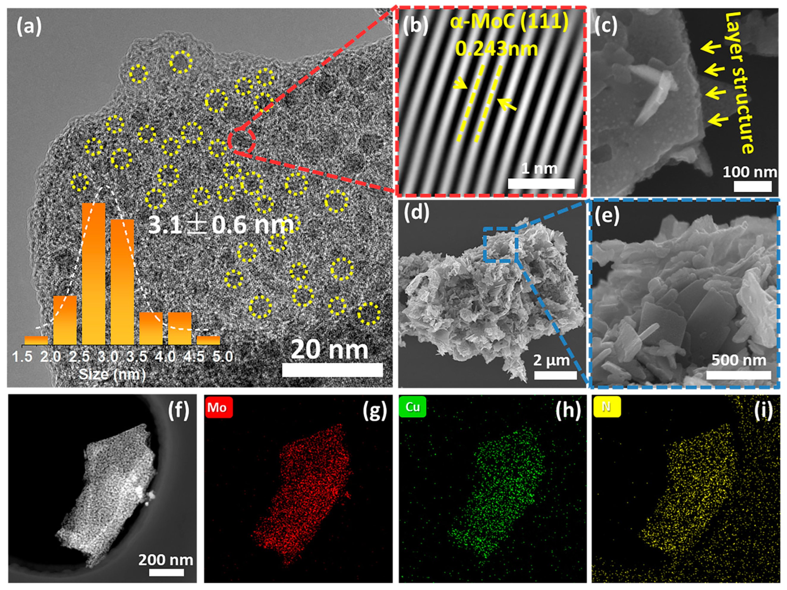
Figure 4.
(a) Full XPS spectra of MoC, N−MoC, Cu−MoC, Co−MoC, N−Co−MoC, and N−Cu−MoC; (b) high−resolution XPS spectra of Mo 3d of MoC, N−MoC, Cu−MoC, and N−Cu−MoC (c) surface Mo2+ percentages of MoC, N−MoC, Cu−MoC, Co−MoC, N−Co−MoC, and N−Cu−MoC determined by XPS profiles; (d) high−resolution XPS spectra of Cu 2p of Cu−MoC and N−Cu−MoC; high−resolution XPS spectra of N 1s of N−Cu−MoC (e) and N−MoC (f).
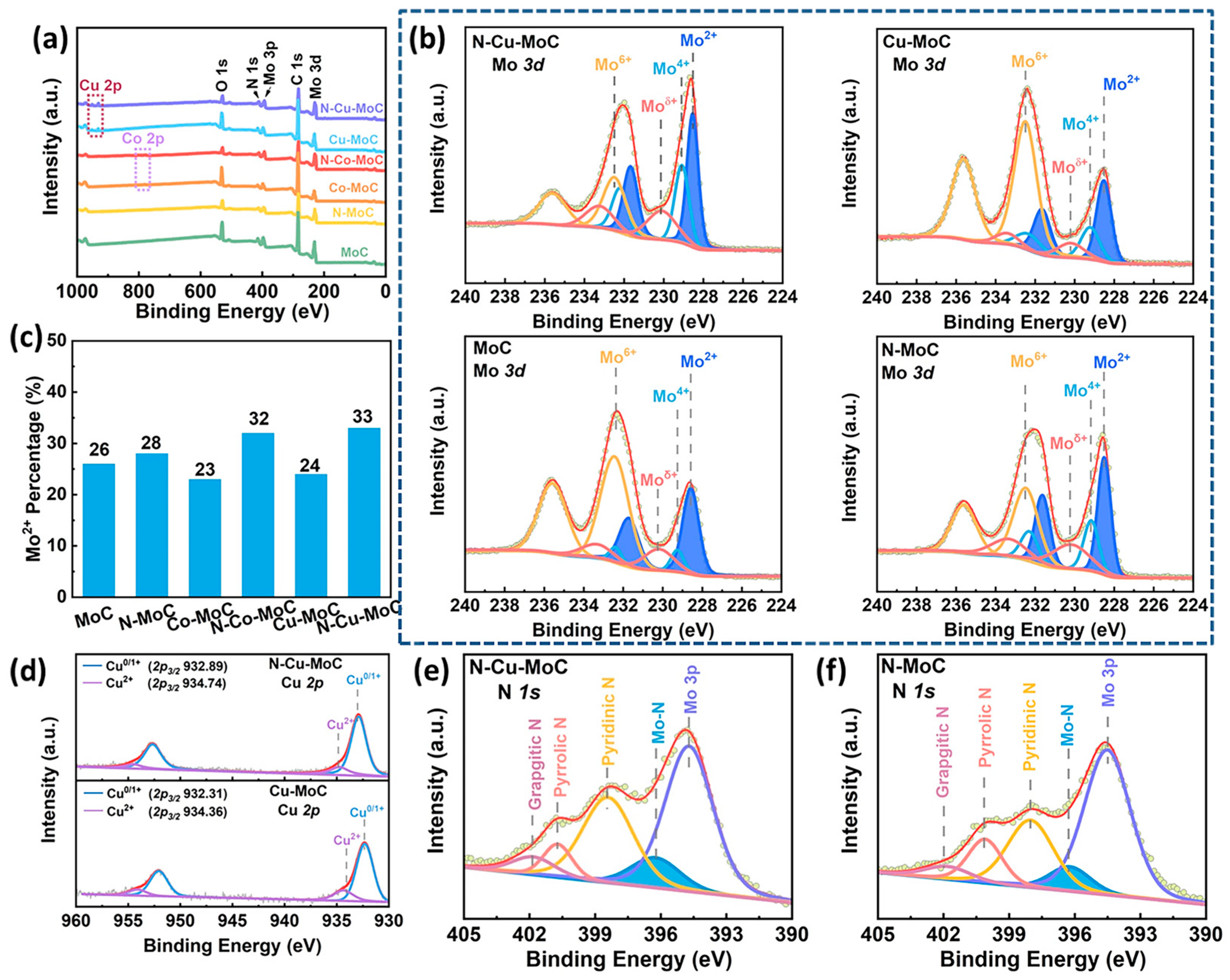
Figure 5.
(a) Polarization curves of MoC, N−MoC, Cu−MoC, Co−MoC, N−Co−MoC, and N−Cu−MoC in 1M KOH electrolyte.; (b) Overpotential corresponding to a current density of 10 mA cm−2; (c) Tafel plots; (d) Estimation of Cdl by plotting the current density variation; (e) Nyquist plots; (f) Polarization curves of N−Cu−MoC and commercial 20% Pt/C; (g) The stabile operation of N−Cu−MoC in 1M KOH electrolyte; (h) LSV curves before and after 1000 cycles of voltametric testing.
Disclaimer/Publisher’s Note: The statements, opinions and data contained in all publications are solely those of the individual author(s) and contributor(s) and not of MDPI and/or the editor(s). MDPI and/or the editor(s) disclaim responsibility for any injury to people or property resulting from any ideas, methods, instructions or products referred to in the content. |
© 2023 by the authors. Licensee MDPI, Basel, Switzerland. This article is an open access article distributed under the terms and conditions of the Creative Commons Attribution (CC BY) license (https://creativecommons.org/licenses/by/4.0/).
Share and Cite
MDPI and ACS Style
Wei, J.; Xu, L.; Hu, L.; Wang, T.; Ma, Y. Dual-Doping Strategy for Enhancing Hydrogen Evolution on Molybdenum Carbide Catalysts. Catalysts 2023, 13, 931. https://doi.org/10.3390/catal13060931
AMA Style
Wei J, Xu L, Hu L, Wang T, Ma Y. Dual-Doping Strategy for Enhancing Hydrogen Evolution on Molybdenum Carbide Catalysts. Catalysts. 2023; 13(6):931. https://doi.org/10.3390/catal13060931
Chicago/Turabian StyleWei, Junling, Li Xu, Lihua Hu, Tiejun Wang, and Yufei Ma. 2023. "Dual-Doping Strategy for Enhancing Hydrogen Evolution on Molybdenum Carbide Catalysts" Catalysts 13, no. 6: 931. https://doi.org/10.3390/catal13060931
Note that from the first issue of 2016, this journal uses article numbers instead of page numbers. See further details here.