
Preparation of High-Efficiency Fe/N-Doped Carbon Catalysts Derived from Graphite Phase Carbon Nitride for Reduction of Oxygen
Abstract
:1. Introduction
2. Results and Discussion
3. Materials and Methods
3.1. Chemicals and Materials
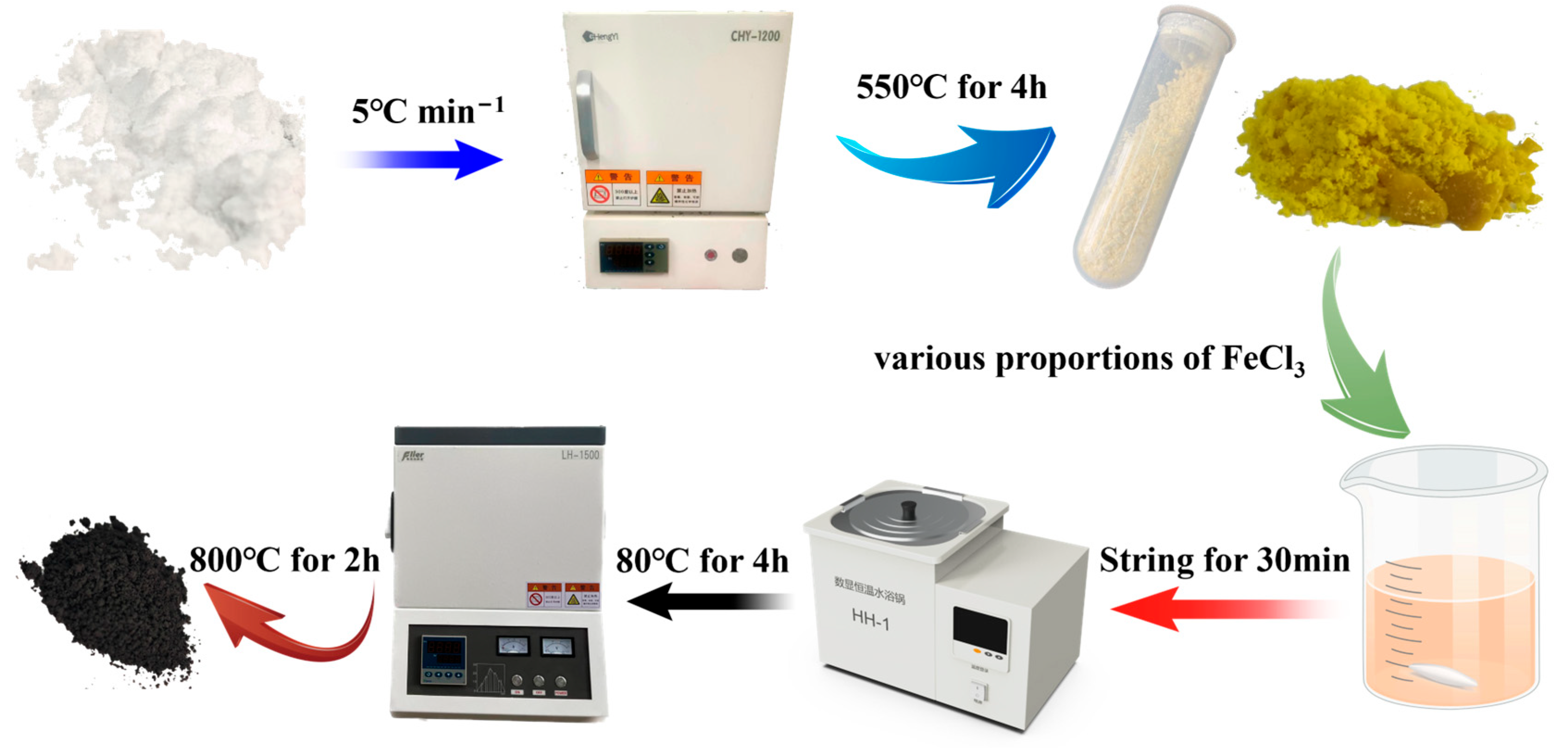
3.2. Preparation of Fe-NC Catalysts
3.3. Characterization of Materials
3.4. Electrochemical Measurements
4. Conclusions
Author Contributions
Funding
Data Availability Statement
Conflicts of Interest
References
- Yang, W.X.; Zhang, Y.Q.; Liu, C.Y.; Jia, J.B. Dual-doped carbon composite for efficient oxygen reduction via electrospinning and incipient impregnation. J. Power Sources 2015, 274, 595–603. [Google Scholar] [CrossRef]
- Sun, T.; Xu, L.; Wang, D.; Li, Y. Metal organic frameworks derived single atom catalysts for electrocatalytic energy conversion. Nano Res. 2019, 12, 2067–2080. [Google Scholar] [CrossRef]
- Zitolo, A.; Goellner, V.; Armel, V.; Sougrati, M.T.; Mineva, T.; Stievano, L.; Fonda, E.; Jaouen, F. Identification of catalytic sites for oxygen reduction in iron- and nitrogen-doped graphene materials. Nat. Mater. 2015, 14, 937–942. [Google Scholar] [CrossRef] [PubMed]
- Borghei, M.; Lehtonen, J.; Liu, L.; Rojas, O.J. Advanced Biomass-Derived Electrocatalysts for the Oxygen Reduction Reaction. Adv. Mater. 2018, 30, 1703691. [Google Scholar] [CrossRef] [PubMed]
- Das, S.; Kundu, A.; Kuila, T.; Murmu, N.C. Recent advancements on designing transition metal-based carbon-supported single atom catalysts for oxygen electrocatalysis: Miles to go for sustainable Zn-air batteries. Energy Storage Mater. 2023, 61, 102890. [Google Scholar] [CrossRef]
- Cui, Q.; Chao, S.J.; Wang, P.H.; Bai, Z.Y.; Yan, H.Y.; Wang, K.; Yang, L. Fe-N/C catalysts synthesized by heat-treatment of iron triazine carboxylic acid derivative complex for oxygen reduction reaction. RSC Adv. 2014, 4, 12168–12174. [Google Scholar] [CrossRef]
- Wang, R.F.; Li, X.S.; Li, H.; Wang, Q.F.; Wang, H.; Wang, W.; Kang, J.; Chang, Y.M.; Lei, Z.Q. Highly stable and effective Pt/carbon nitride (CNx) modified SiO2 electrocatalyst for oxygen reduction reaction. Int. J. Hydrogen Energy 2011, 36, 5775–5781. [Google Scholar] [CrossRef]
- Yan, L.T.; Yu, J.L.; Houston, J.; Flores, N.; Luo, H.M. Biomass derived porous nitrogen doped carbon for electrochemical devices. Green Energy Environ. 2017, 2, 84–99. [Google Scholar] [CrossRef]
- Park, S.; Kim, J.; Kwon, K. A review on biomass-derived N-doped carbons as electrocatalysts in electrochemical energy applications. Chem. Eng. J. 2022, 446, 137116. [Google Scholar] [CrossRef]
- Kundu, A.; Kuila, T.; Murmu, N.C.; Samanta, P.; Das, S. Metal-organic framework-derived advanced oxygen electrocatalysts as air-cathodes for Zn-air batteries: Recent trends and future perspectives. Mater. Horiz. 2023, 10, 745–787. [Google Scholar] [CrossRef]
- Hu, Y.; Jensen, J.O.; Zhang, W.; Cleemann, L.N.; Xing, W.; Bjerrum, N.J.; Li, Q.F. Hollow Spheres of Iron Carbide Nanoparticles Encased in Graphitic Layers as Oxygen Reduction Catalysts. Angew. Chem. Int. Ed. 2014, 53, 3675–3679. [Google Scholar] [CrossRef] [PubMed]
- Shein, I.R.; Medvedeva, N.I.; Ivanovskii, A.L. Electronic and structural properties of cementite-type M3X (M = Fe, Co, Ni; X = C or B) by first principles calculations. Phys. B Condens. Matter 2006, 371, 126–132. [Google Scholar] [CrossRef]
- Guo, J.N.; Ning, M.Y.; Xiang, Z.H. Highly efficient iron-nitrogen electrocatalyst derived from covalent organic polymer for oxygen reduction. J. Energy Chem. 2017, 26, 1168–1173. [Google Scholar] [CrossRef]
- Hu, K.; Tao, L.; Liu, D.D.; Huo, J.; Wang, S.Y. Sulfur-Doped Fe/N/C Nanosheets as Highly Efficient Electrocatalysts for Oxygen Reduction Reaction. ACS Appl. Mater. Interfaces 2016, 8, 19379–19385. [Google Scholar] [CrossRef] [PubMed]
- Xue, D.P.; Yuan, P.F.; Jiang, S.; Wei, Y.F.; Zhou, Y.; Dong, C.L.; Yan, W.F.; Mu, S.C.; Zhang, J.N. Altering the spin state of Fe-N-C through ligand field modulation of single-atom sites boosts the oxygen reduction reaction. Nano Energy 2023, 105, 108020. [Google Scholar] [CrossRef]
- Zeng, R.; Yang, Y.; Feng, X.R.; Li, H.Q.; Gibbs, L.M.; DiSalvo, F.J.; Abruña, H.D. Nonprecious transition metal nitrides as efficient oxygen reduction electrocatalysts for alkaline fuel cells. Sci. Adv. 2022, 8, eabj1584. [Google Scholar] [CrossRef] [PubMed]
- Asahi, R.; Morikawa, T.; Ohwaki, T.; Aoki, K.; Taga, Y. Visible-Light Photocatalysis in Nitrogen-Doped Titanium Oxides. Science 2001, 293, 269–271. [Google Scholar] [CrossRef] [PubMed]
- Zhu, Y.S.; Zhang, B.S.; Liu, X.; Wang, D.W.; Su, D.S. Unravelling the Structure of Electrocatalytically Active Fe-N Complexes in Carbon for the Oxygen Reduction Reaction. Angew. Chem. Int. Ed. 2014, 53, 10673–10677. [Google Scholar] [CrossRef] [PubMed]
- Lu, X.Y.; Li, Y.Q.; Yang, P.X.; Wan, Y.B.; Wang, D.; Xu, H.; Liu, L.L.; Xiao, L.H.; Li, R.P.; Wang, G.Z.; et al. Atomically dispersed Fe-N-C catalyst with densely exposed Fe-N4 active sites for enhanced oxygen reduction reaction. Chem. Eng. J. 2024, 485, 149529. [Google Scholar] [CrossRef]
- Gong, K.; Du, F.; Xia, Z.; Durstock, M.; Dai, L. Nitrogen-Doped Carbon Nanotube Arrays with High Electrocatalytic Activity for Oxygen Reduction. Science 2009, 323, 760–764. [Google Scholar] [CrossRef]
- Jiang, W.J.; Gu, L.; Li, L.; Zhang, Y.; Zhang, X.; Zhang, L.J.; Wang, J.Q.; Hu, J.S.; Wei, Z.D.; Wan, L.J. Understanding the High Activity of Fe-N-C Electrocatalysts in Oxygen Reduction: Fe/Fe3C Nanoparticles Boost the Activity of Fe-Nx. J. Am. Chem. Soc. 2016, 138, 3570–3578. [Google Scholar] [CrossRef]
- Sheng, Z.H.; Shao, L.; Chen, J.J.; Bao, W.J.; Wang, F.B.; Xia, X.H. Catalyst-Free Synthesis of Nitrogen-Doped Graphene via Thermal Annealing Graphite Oxide with Melamine and Its Excellent Electrocatalysis. ACS Nano 2011, 5, 4350–4358. [Google Scholar] [CrossRef]
- Gu, L.Z.; Jiang, L.H.; Jin, J.T.; Liu, J.; Sun, G.Q. Yolk-shell structured iron carbide/N-doped carbon composite as highly efficient and stable oxygen reduction reaction electrocatalyst. Carbon 2015, 82, 572–578. [Google Scholar] [CrossRef]
- Ye, Y.F.; Li, H.B.; Cai, F.; Yan, C.C.; Si, R.; Miao, S.; Li, Y.S.; Wang, G.X.; Bao, X.H. Two-Dimensional Mesoporous Carbon Doped with Fe-N Active Sites for Efficient Oxygen Reduction. ACS Catal. 2017, 7, 7638–7646. [Google Scholar] [CrossRef]
- Yan, J.; Gu, T.Y.; Shi, R.H.; Chen, X.; Rümmeli, M.H.; Yang, R.Z. Heteroatom sulfur-doping in single-atom Fe-NC catalysts for durable oxygen reduction reaction in both alkaline and acidic media. J. Mater. Chem. A 2023, 11, 16180–16189. [Google Scholar] [CrossRef]
- Zhou, M.; Yan, S.X.; Wang, Q.; Tan, M.X.; Wang, D.Y.; Yu, Z.Q.; Luo, S.H.; Zhang, Y.H.; Liu, X. Walnut septum-derived hierarchical porous carbon for ultra-high-performance supercapacitors. Rare Met. 2022, 41, 2280–2291. [Google Scholar] [CrossRef]
- Huang, B.B.; Liu, Y.C.; Xie, Z.L. Biomass derived 2D carbons via a hydrothermal carbonization method as efficient bifunctional ORR/HER electrocatalysts. J. Mater. Chem. A 2017, 5, 23481–23488. [Google Scholar] [CrossRef]
- Wang, W.; Gong, J.L.; Long, Q.; Wang, H.T.; Huang, J.L.; Dang, W.; Chen, L.; Li, G.Y.; Hou, Z.H.; Xu, W.Y. Fe-Fe3N composite nitrogen-doped carbon framework: Multi-dimensional cross-linked structure boosting performance for the oxygen reduction reaction electrocatalysis and zinc-air batteries. Appl. Surf. Sci. 2023, 639, 158218. [Google Scholar] [CrossRef]
- Zhang, Y.P.; Wang, N.; Jia, N.; Wang, J.; Sun, J.; Shi, F.; Liu, Z.H.; Jiang, R.B. A Low-Cost and Facile Method for the Preparation of Fe-N/C-Based Hybrids with Superior Catalytic Performance toward Oxygen Reduction Reaction. Adv. Mater. Interfaces 2019, 6, 1900273. [Google Scholar] [CrossRef]
- Cui, X.Y.; Yang, S.B.; Yan, X.X.; Leng, J.G.; Shuang, S.; Ajayan, P.M.; Zhang, Z.J. Pyridinic-Nitrogen-Dominated Graphene Aerogels with Fe-N-C Coordination for Highly Efficient Oxygen Reduction Reaction. Adv. Funct. Mater. 2016, 26, 5708–5717. [Google Scholar] [CrossRef]
- Kim, S.J.; Mahmood, J.; Kim, C.; Han, G.F.; Kim, S.W.; Jung, S.M.; Zhu, G.M.; De Yoreo, J.J.; Kim, G.; Baek, J.B. Defect-Free Encapsulation of Fe0 in 2D Fused Organic Networks as a Durable Oxygen Reduction Electrocatalyst. J. Am. Chem. Soc. 2018, 140, 1737–1742. [Google Scholar] [CrossRef] [PubMed]
- Kudin, K.N.; Ozbas, B.; Schniepp, H.C.; Prud’homme, R.K.; Aksay, I.A.; Car, R. Raman spectra of graphite oxide and functionalized graphene sheets. Nano Lett. 2008, 8, 36–41. [Google Scholar] [CrossRef] [PubMed]
- Gao, S.; Lin, Y.; Jiao, X.C.; Sun, Y.F.; Luo, Q.Q.; Zhang, W.H.; Li, D.Q.; Yang, J.L.; Xie, Y. Partially oxidized atomic cobalt layers for carbon dioxide electroreduction to liquid fuel. Nature 2016, 529, 68–71. [Google Scholar] [CrossRef] [PubMed]
- Yan, D.F.; Li, Y.X.; Huo, J.; Chen, R.; Dai, L.M.; Wang, S.Y. Defect Chemistry of Nonprecious-Metal Electrocatalysts for Oxygen Reactions. Adv. Mater. 2017, 29, 1606459. [Google Scholar] [CrossRef] [PubMed]
- He, W.H.; Jiang, C.H.; Wang, J.B.; Lu, L.H. High-Rate Oxygen Electroreduction over Graphitic-N Species Exposed on 3D Hierarchically Porous Nitrogen-Doped Carbons. Angew. Chem. Int. Ed. 2014, 53, 9503–9507. [Google Scholar] [CrossRef] [PubMed]
- Liang, J.; Du, X.; Gibson, C.; Du, X.W.; Qiao, S.Z. N-Doped Graphene Natively Grown on Hierarchical Ordered Porous Carbon for Enhanced Oxygen Reduction. Adv. Mater. 2013, 25, 6226–6231. [Google Scholar] [CrossRef]
- Yi, J.D.; Zhang, M.D.; Hou, Y.; Huang, Y.B.; Cao, R. N-Doped Carbon Aerogel Derived from a Metal-Organic Framework Foam as an Efficient Electrocatalyst for Oxygen Reduction. Chem. Asian J. 2019, 14, 3642–3647. [Google Scholar] [CrossRef]
- Aniruddha, K.; Saikat, B.; Srijib, D.; Haradhan, K.; Chun-Won, K.; Tapas, K.; Naresh Chandra, M. General Approach to Synthesize Multilayer Graphitic Carbon-Nanotube-Encapsulated NiCo Alloys as Trifunctional Electrocatalysts: Deciphering the Role of N-Dopants. ACS Appl. Energy Mater. 2022, 5, 14445–14454. [Google Scholar]
- Guo, D.H.; Shibuya, R.; Akiba, C.; Saji, S.; Kondo, T.; Nakamura, J. Active sites of nitrogen-doped carbon materials for oxygen reduction reaction clarified using model catalysts. Science 2016, 351, 361–365. [Google Scholar] [CrossRef]
- Zhu, C.; Shi, Q.; Xu, B.Z.; Fu, S.; Wan, G.; Yang, C.; Yao, S.; Song, J.; Zhou, H.; Du, D.; et al. Hierarchically Porous M–N–C (M = Co and Fe) Single-Atom Electrocatalysts with Robust MNx Active Moieties Enable Enhanced ORR Performance. Adv. Energy Mater. 2018, 8, 1801956. [Google Scholar] [CrossRef]
- Yamashita, T.; Hayes, P. Analysis of XPS spectra of Fe2+ and Fe3+ ions in oxide materials. Appl. Surf. Sci. 2008, 254, 2441–2449. [Google Scholar] [CrossRef]
- Velazquez-Palenzuela, A.; Zhang, L.; Wang, L.C.; Cabot, P.L.; Brillas, E.; Tsay, K.; Zhang, J.J. Carbon-Supported Fe-Nx Catalysts Synthesized by Pyrolysis of the Fe(II)-2,3,5,6-Tetra(2-pyridyl)pyrazine Complex: Structure, Electrochemical Properties, and Oxygen Reduction Reaction Activity. J. Phys. Chem. C 2011, 115, 12929–12940. [Google Scholar] [CrossRef]
- Liu, Y.Y.; Ruan, J.M.; Sang, S.B.; Zhou, Z.C.; Wu, Q.M. Iron and nitrogen co-doped carbon derived from soybeans as efficient electro-catalysts for the oxygen reduction reaction. Electrochim. Acta 2016, 215, 388–397. [Google Scholar] [CrossRef]
- Huo, J.J.; Lu, L.; Shen, Z.Y.; Liu, Y.; Guo, J.J.; Liu, Q.B.; Wang, Y.; Liu, H.; Wu, M.H.; Wang, G.X. A rational synthesis of single-atom iron-nitrogen electrocatalysts for highly efficient oxygen reduction reaction. J. Mater. Chem. A 2020, 8, 16271–16282. [Google Scholar] [CrossRef]
- Zhang, D.; Ding, R.X.; Zhang, C.Q.; Tang, Y.Z.; Yuan, T.J.; Dong, Q.P.; Bi, L.S.; Shi, S.; He, Y. Efficient Synthesis of Fe/N-Doped Carbon Nanotube as Highly Active Catalysts for Oxygen Reduction Reaction in Alkaline Media. Langmuir 2022, 38, 9310–9320. [Google Scholar] [CrossRef]


| Samples | Quarternary-N (%) | Graphitic-N (%) | Pyrrolic-N (%) | Pyridinic-N (%) |
|---|---|---|---|---|
| 0.1 Fe | 7.97 | 22.59 | 13.69 | 55.74 |
| 0.5 Fe | 8.42 | 28.27 | 6.88 | 56.43 |
| 1.5 Fe | 6.71 | 27.37 | 11.72 | 54.21 |
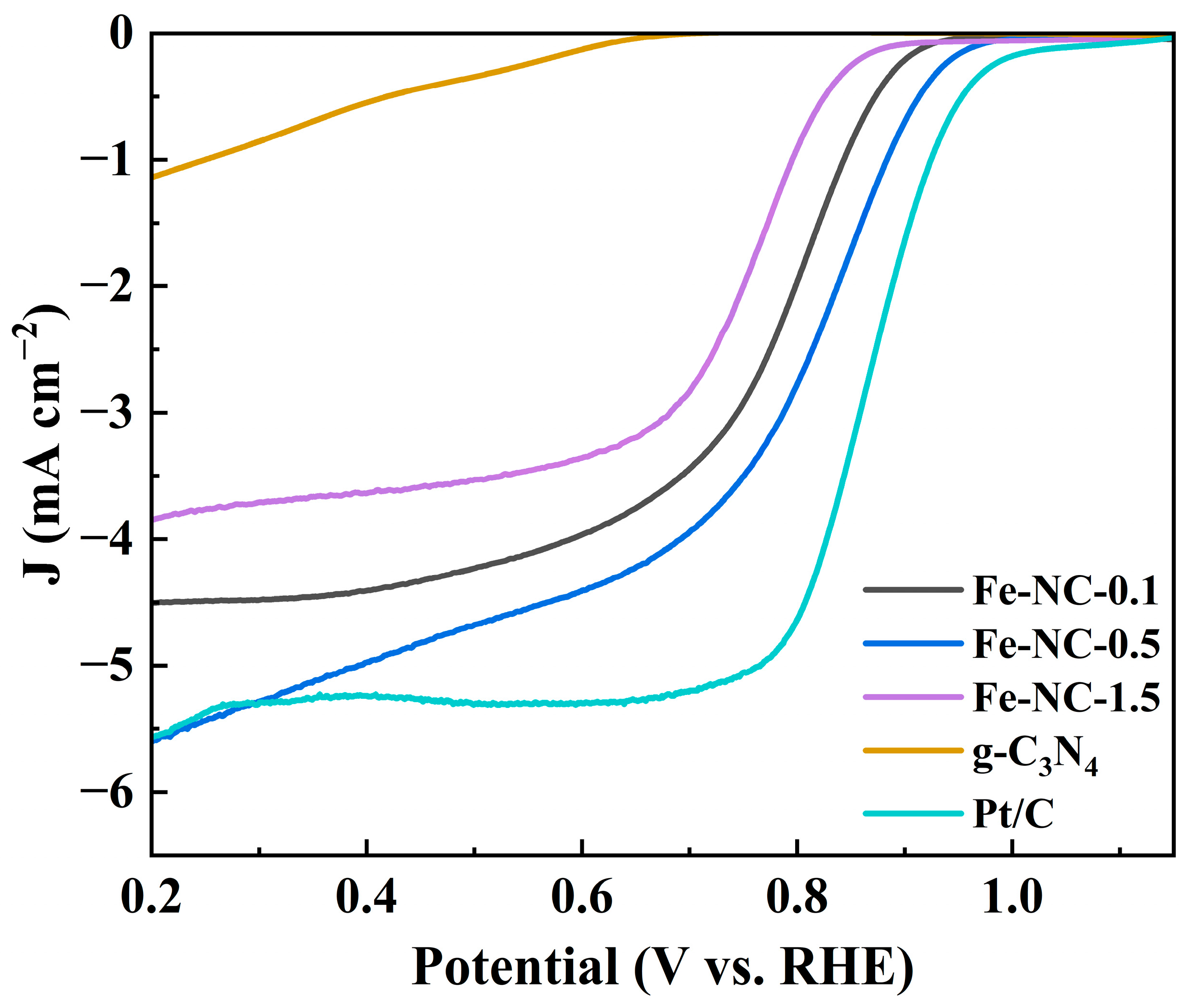
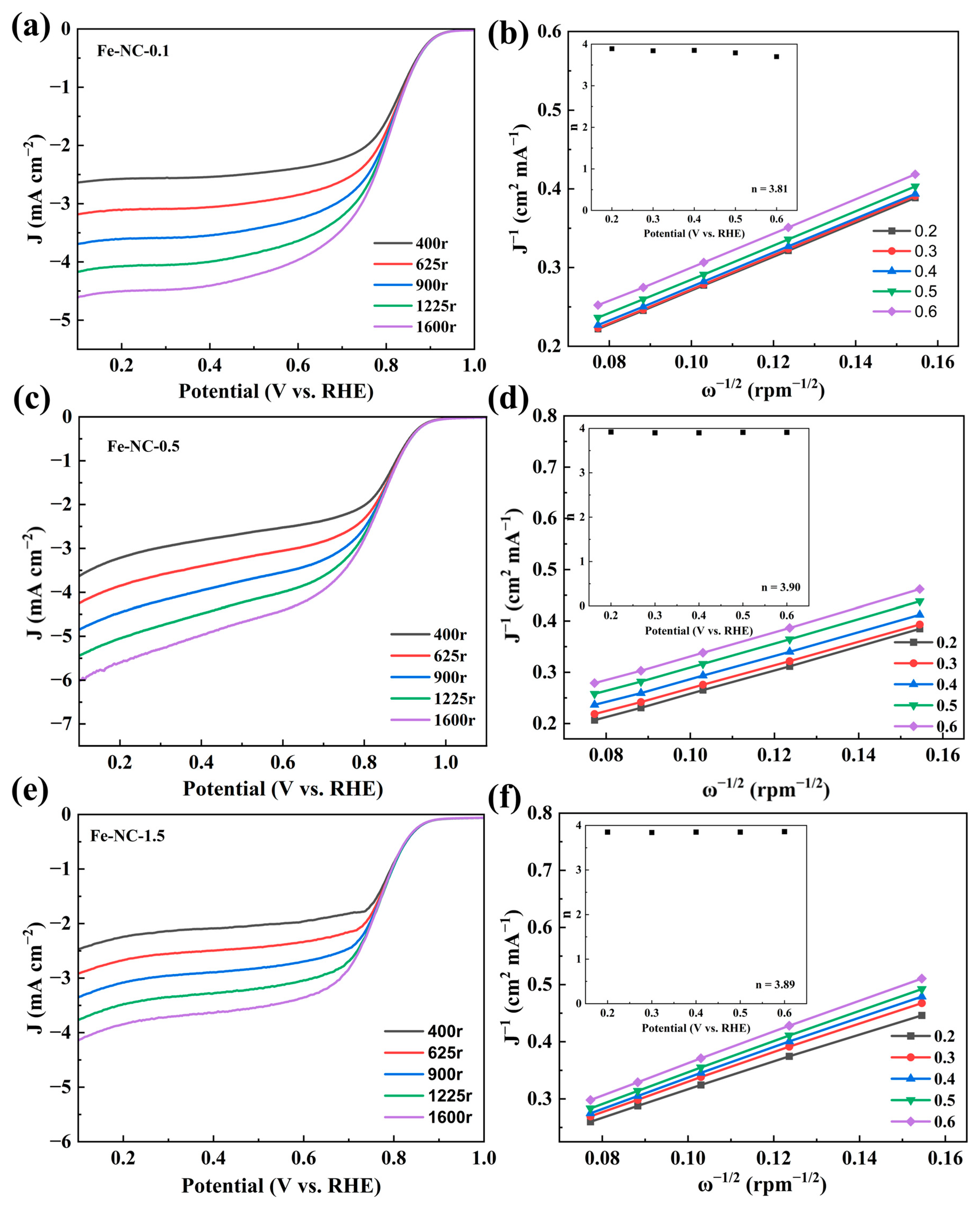
| Samples | Onset Potential (Eonset V) | Half-Wave Potential (E1/2 V) | Limiting Current Density (mA cm−2) | Electron Transfer Number (n) |
|---|---|---|---|---|
| 0.1 Fe | 0.92 | 0.76 | 4.6 | 3.81 |
| 0.5 Fe | 0.96 | 0.81 | 5.97 | 3.90 |
| 1.5 Fe | 0.88 | 0.77 | 4.14 | 3.89 |
| Pt/C | 0.98 | 0.84 | 5.48 | — |
| g-C3N4 | 0.69 | — | 1.4 | — |
Disclaimer/Publisher’s Note: The statements, opinions and data contained in all publications are solely those of the individual author(s) and contributor(s) and not of MDPI and/or the editor(s). MDPI and/or the editor(s) disclaim responsibility for any injury to people or property resulting from any ideas, methods, instructions or products referred to in the content. |
© 2024 by the authors. Licensee MDPI, Basel, Switzerland. This article is an open access article distributed under the terms and conditions of the Creative Commons Attribution (CC BY) license (https://creativecommons.org/licenses/by/4.0/).
Share and Cite
Wang, Y.; Liu, W.; Wang, R.; Wang, Q.; Luo, S.; Hou, P.; Zhang, Y.; Yan, S.; Liu, X.; Guo, J. Preparation of High-Efficiency Fe/N-Doped Carbon Catalysts Derived from Graphite Phase Carbon Nitride for Reduction of Oxygen. Catalysts 2024, 14, 279. https://doi.org/10.3390/catal14040279
Wang Y, Liu W, Wang R, Wang Q, Luo S, Hou P, Zhang Y, Yan S, Liu X, Guo J. Preparation of High-Efficiency Fe/N-Doped Carbon Catalysts Derived from Graphite Phase Carbon Nitride for Reduction of Oxygen. Catalysts. 2024; 14(4):279. https://doi.org/10.3390/catal14040279
Chicago/Turabian StyleWang, Yan, Wuxin Liu, Rongzhe Wang, Qing Wang, Shaohua Luo, Pengqing Hou, Yahui Zhang, Shengxue Yan, Xin Liu, and Jing Guo. 2024. "Preparation of High-Efficiency Fe/N-Doped Carbon Catalysts Derived from Graphite Phase Carbon Nitride for Reduction of Oxygen" Catalysts 14, no. 4: 279. https://doi.org/10.3390/catal14040279