
In Search of Governing Gas Flow Mechanism through Metal Solid Foams

 , ,
, ,
Abstract
:
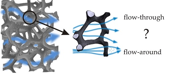
1. Introduction
2. Results
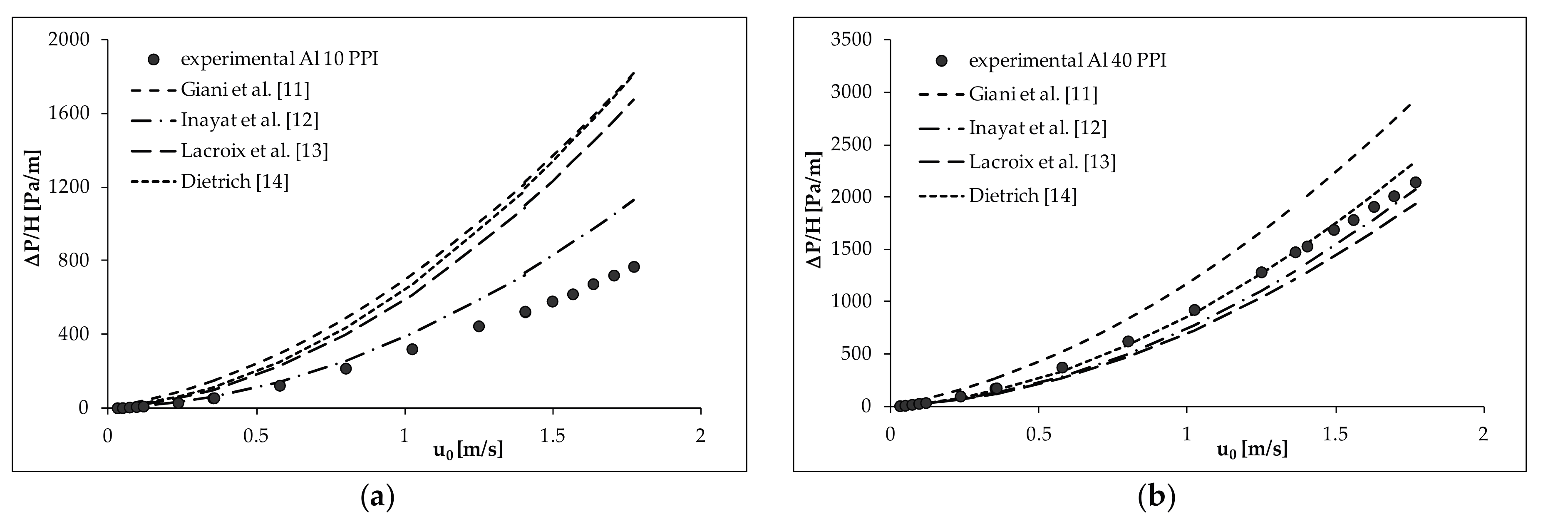
2.1. Pressure Drop Measurement
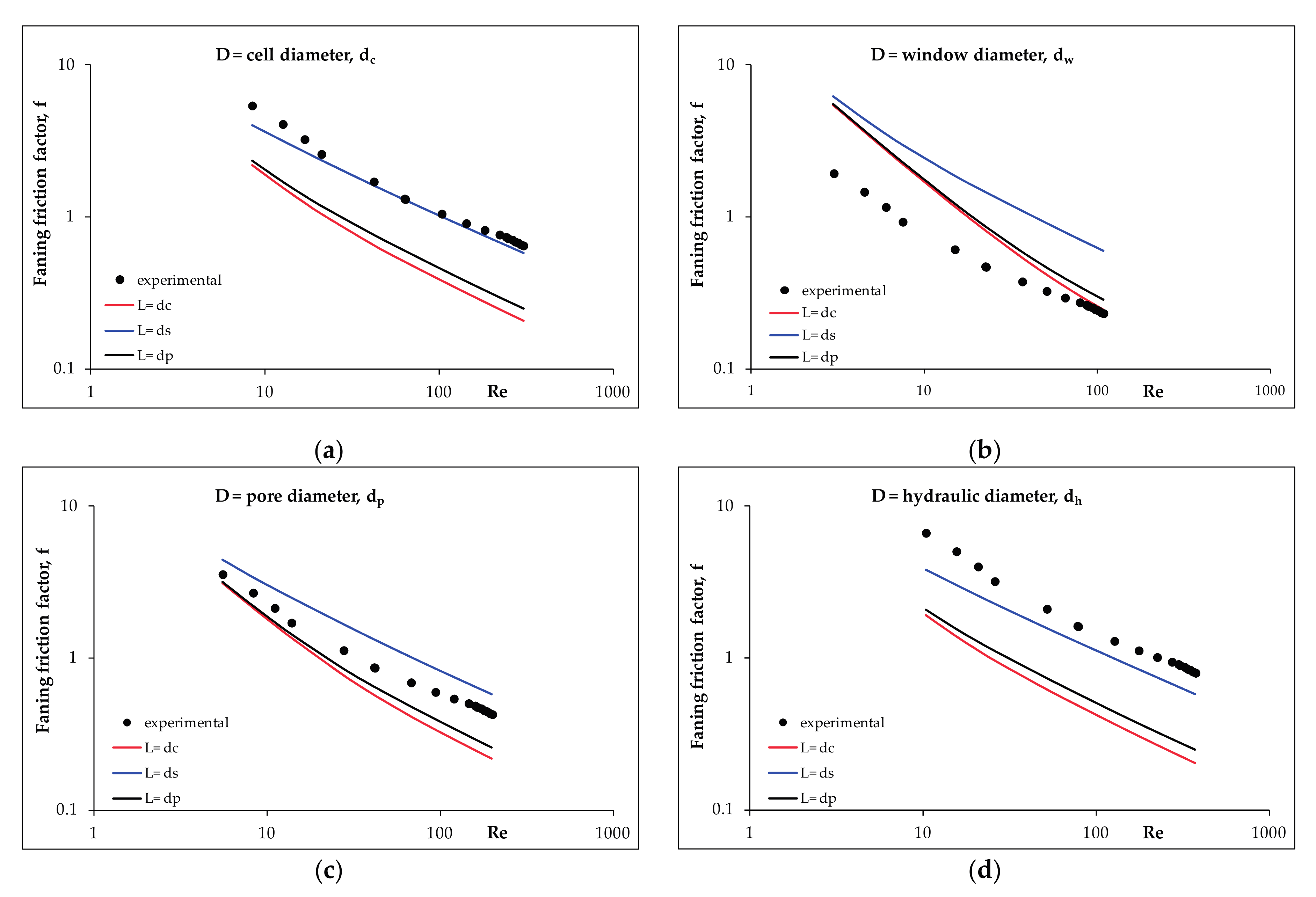
2.2. Pressure Drop Modelling
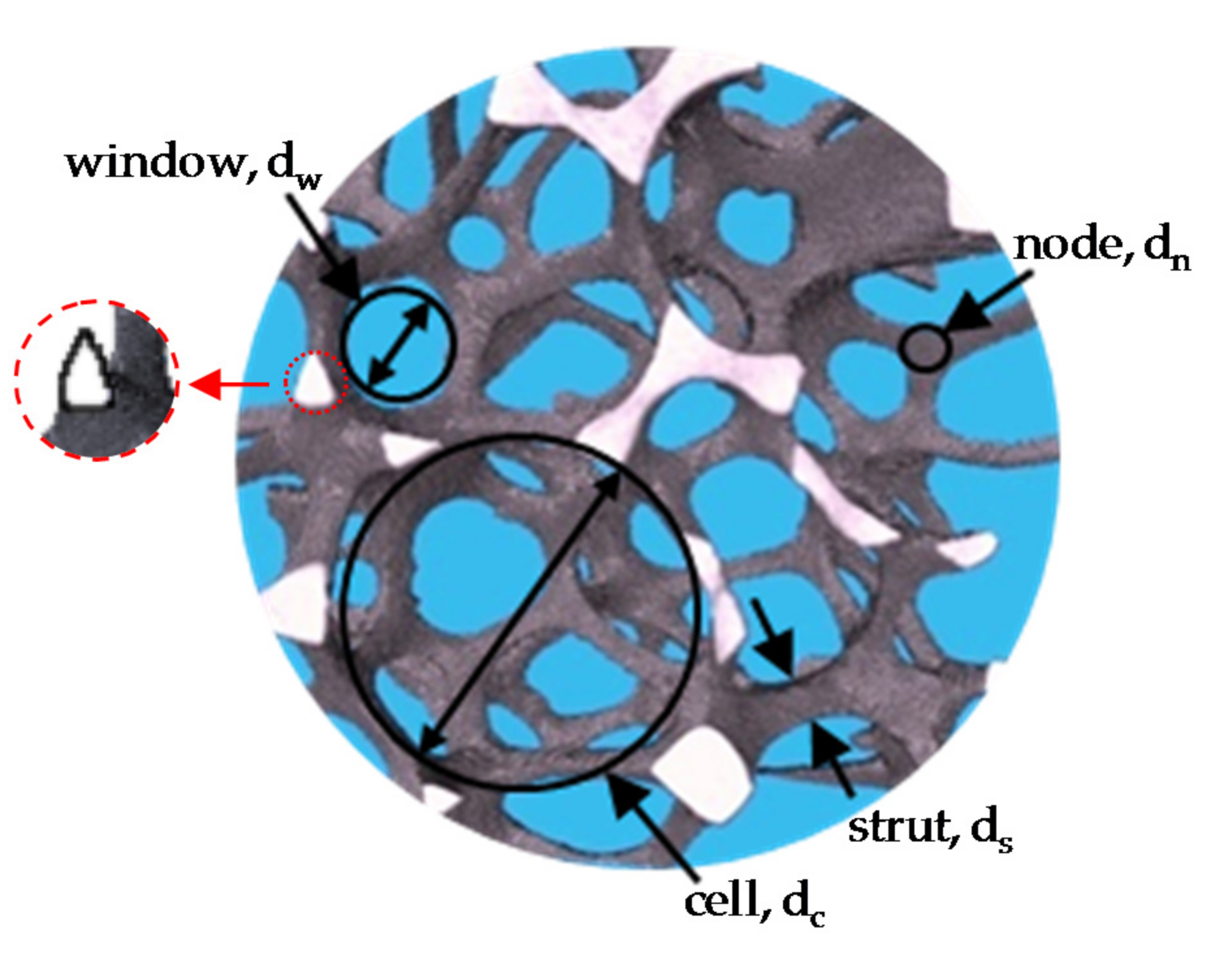
- the average cell diameter, dc
- the average window diameter, dw
- the average pore diameter, dp (i.e., both cell and window diameter)
- the hydraulic diameter, dh = 4ε/Sv
- the average cell diameter, dc
- the average pore diameter, dp
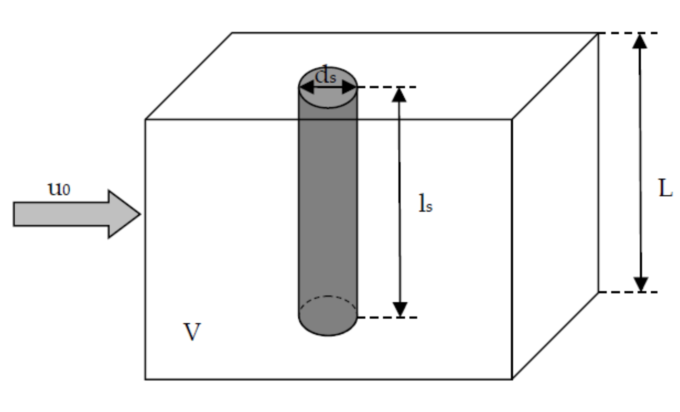
- the average strut diameter (thickness), ds
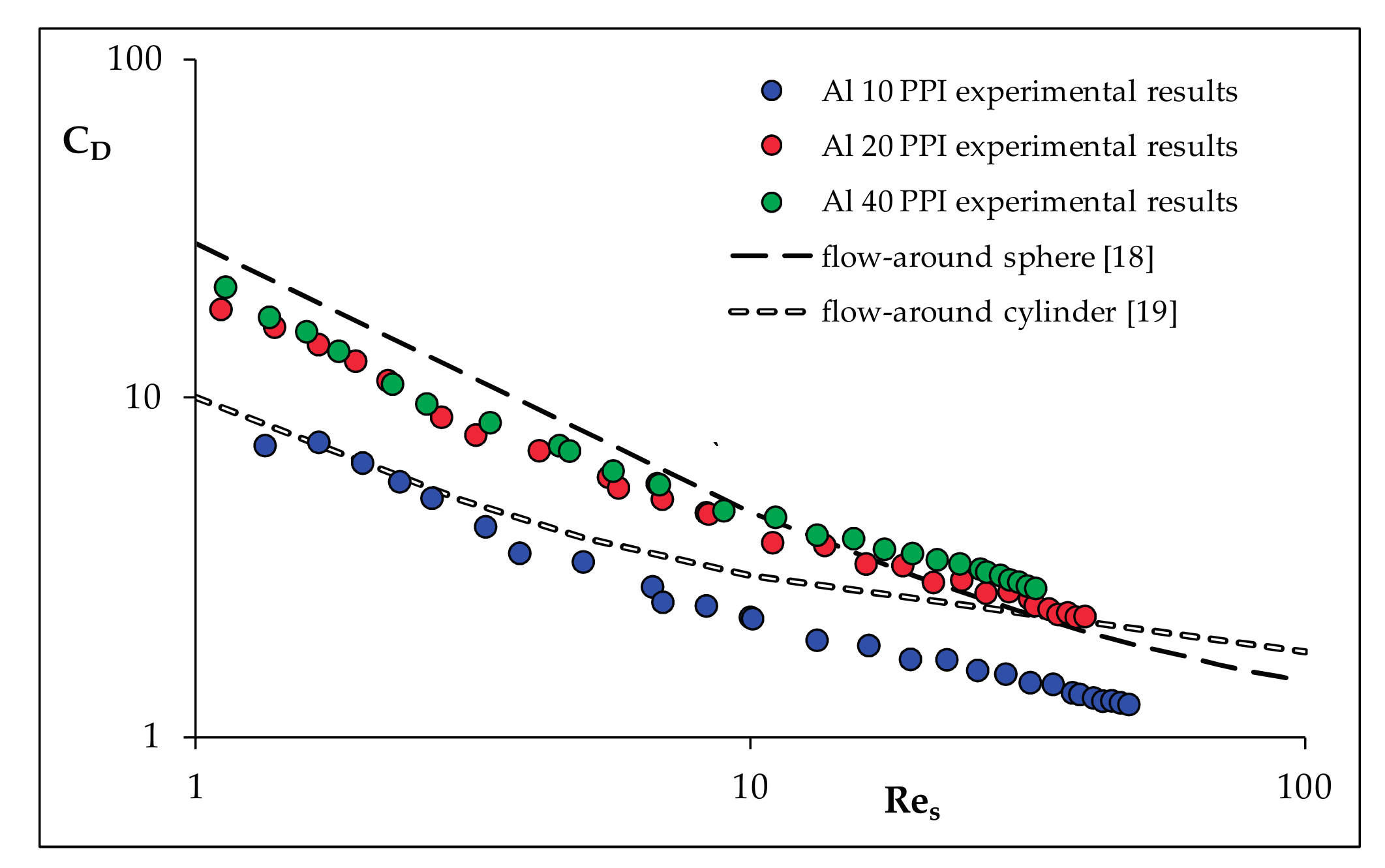
3. Discussion
4. Materials and Methods
4.1. Foam Morphology
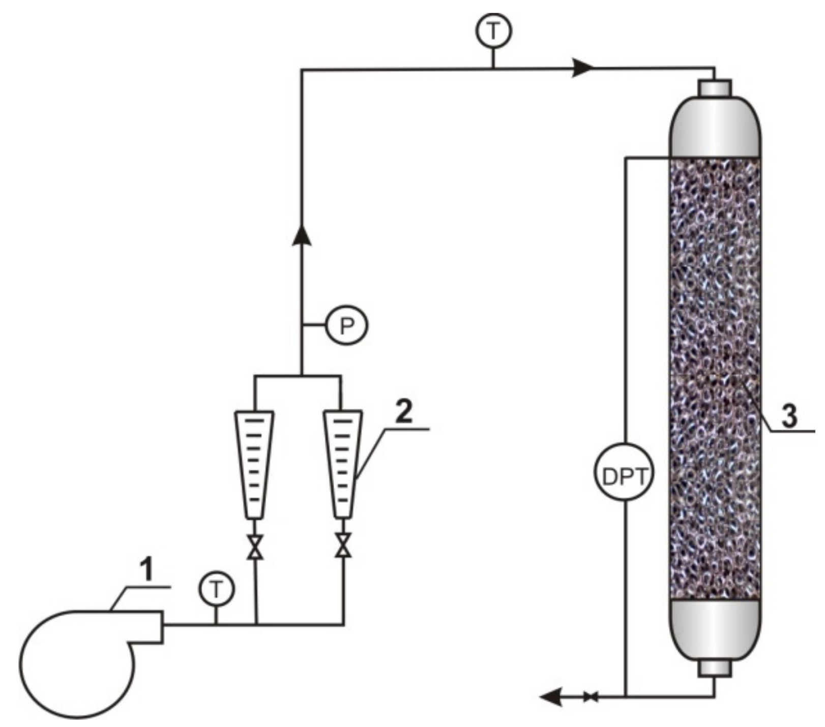
4.2. Flow Resistance Measurements
5. Conclusions
Acknowledgments
Author Contributions
Conflicts of Interest
Appendix A
References
- Edouard, D.; Lacroix, M.; Huu, C.P.; Luck, F. Pressure drop modeling on SOLID foam: State-of-the art correlation. Chem. Eng. J. 2008, 144, 299–311. [Google Scholar] [CrossRef]
- Ochońska-Kryca, J.; Iwaniszyn, M.; Piątek, M.; Jodłowski, P.J.; Thomas, J.; Kołodziej, A.; Łojewska, J. Mass transport and kinetics in structured steel foam reactor with Cu-ZSM-5 catalyst for SCR of NOx with ammonia. Catal. Today 2013, 216, 135–141. [Google Scholar] [CrossRef]
- Grosse, J.; Dietrich, B.; Garrido, G.I.; Habisreuther, P.; Zarzalis, N.; Martin, H.; Kind, M.; Kraushaar-Czarnetzki, B. Morphological characterization of ceramic sponges for applications in chemical engineering. Ind. Eng. Chem. Res. 2009, 48, 10395–10401. [Google Scholar]
- Vicente, J.; Topin, F.; Daurelle, J.V. Open celled material structural properties measurement: From morphology to transport properties. Mater. Trans. 2006, 47, 2195–2202. [Google Scholar] [CrossRef]
- Inayat, A.; Freund, H.; Zeiser, T.; Schwieger, W. Determining the specific surface area of ceramic foams: The tetrakaidecahedra model revisited. Chem. Eng. Sci. 2011, 66, 1179–1188. [Google Scholar] [CrossRef]
- Garrido, G.I.; Patcas, F.C.; Lang, S.; Kraushaar-Czarnetzki, B. Mass transfer and pressure drop in ceramic foams: A description for different pore sizes and porosities. Chem. Eng. Sci. 2008, 63, 5202–5217. [Google Scholar] [CrossRef]
- Buciuman, F.C.; Kraushaar-Czarnetzki, B. Ceramic foam monoliths as catalyst carriers. 1. Adjustment and description of the morphology. Ind. Eng. Chem. Res. 2003, 42, 1863–1869. [Google Scholar] [CrossRef]
- Lucci, F.; Della Torre, A.; Montenegro, G.; Kaufmann, R.; Dimopoulos Eggenschwiler, P. Comparison of geometrical, momentum and mass transfer characteristics of real foams to Kelvin cell lattices for catalyst applications. Int. J. Heat Mass Transf. 2017, 108, 341–350. [Google Scholar] [CrossRef]
- Bhattacharya, A.; Calmidi, V.V.; Mahajan, R.L. Thermophysical properties of high porosity metal foams. Int. J. Heat Mass Transf. 2002, 45, 1017–1031. [Google Scholar] [CrossRef]
- Inayat, A.; Freund, H.; Schwab, A.; Zeiser, T.; Schwieger, W. Predicting the specific surface area and pressure drop of reticulated ceramic foams used as catalyst support. Adv. Eng. Mater. 2011, 13, 990–995. [Google Scholar] [CrossRef]
- Giani, L.; Groppi, G.; Tronconi, E. Mass-transfer characterization of metallic foams as supports for structured catalysts. Ind. Eng. Chem. Res. 2005, 44, 4993–5002. [Google Scholar] [CrossRef]
- Inayat, A.; Klumpp, M.; Lammermann, M.; Freund, H.; Schwieger, W. Development of a new pressure drop correlation for open-cell foams based completely on theoretical grounds: Taking into account strut shape and geometric tortuosity. Chem. Eng. J. 2016, 287, 704–719. [Google Scholar] [CrossRef]
- Lacroix, M.; Nguyen, P.; Schweich, D.; Huu, C.P.; Savin-Poncet, S.; Edouard, D. Pressure drop measurements and modeling on SiC foams. Chem. Eng. Sci. 2007, 62, 3259–3267. [Google Scholar] [CrossRef]
- Dietrich, B. Pressure drop correlation for ceramic and metal sponges. Chem. Eng. Sci. 2012, 74, 192–199. [Google Scholar] [CrossRef]
- Richardson, J.T.; Peng, Y.; Remue, D. Properties of ceramic foam catalyst supports: Pressure drop. Appl. Catal. A 2000, 204, 19–32. [Google Scholar] [CrossRef]
- Schlegel, A.; Benz, P.; Buser, S. Warmeubertragung und Druckabfall in keramischen Schaumstrukturen bei erzwungener Stromung. Warme- Und Stofffubertragung 1993, 28, 259–266. [Google Scholar] [CrossRef]
- Almedeij, J. Drag coefficient of flow around a sphere: Matching asymptotically the wide trend. Powder Technol. 2008, 186, 218–223. [Google Scholar] [CrossRef]
- Torobin, L.B.; Gauvin, W.H. Fundamental aspects of solids-gas flow: Part I: Introductory concepts and idealised sphere motion in viscous regime. Can. J. Chem. Eng. 1959, 37, 129–141. [Google Scholar] [CrossRef]
- Tong, L.S.; London, A.L. Heat-transfer and flow-friction characteristics of woven-screen and crossed-rod matrixes. Trans. ASME 1957, 57, 1558–1570. [Google Scholar]
- Iwaniszyn, M.; Ochonska, J.; Gancarczyk, A.; Jodlowski, P.; Knapik, A.; Lojewska, J.; Janowska-Renkas, E.; Kolodziej, A. Short-channel structured reactor as a catalytic afterburner. Top. Catal. 2013, 56, 273–278. [Google Scholar] [CrossRef]
- Shah, R.K. A correlation for laminar hydrodynamic entry length solutions for circular and noncircular ducts. J. Fluids Eng. 1978, 100, 177. [Google Scholar] [CrossRef]
- Shah, R.K.; London, A.L. Laminar Flow Forced Convection in Ducts: A Source Book for Compact Heat Exchanger Analytical Data; Academic Press: New York, NY, USA, 1978. [Google Scholar]
- Kolodziej, A.; Lojewska, J.; Jaroszynski, M.; Gancarczyk, A.; Jodlowski, P. Heat transfer and flow resistance for stacked wire gauzes: Experiments and modelling. Int. J. Heat Fluid Flow 2012, 33, 101–108. [Google Scholar] [CrossRef]
- ERG Materials and Aerospace Corp. Available online: http://www.ergaerospace.com (accessed on 6 February 2017).
- Leszczyński, B.; Gancarczyk, A.; Wróbel, A.; Piątek, M.; Łojewska, J.; Kołodziej, A.; Pędrys, R. Global and local thresholding methods applied to X-ray microtomographic analysis of metallic foams. J. Nondestruct. Eval. 2016. [Google Scholar] [CrossRef]
- iMorph Software. Available online: http://imorph.fr (accessed on 6 February 2017).


| Foam | Pore Diameter, dp (mm) | Cell Diameter, dc (mm) | Window Diameter, dw (mm) | Strut Diameter, ds (mm) | Porosity, ε | Specific Surface Area, Sv (m2/m3) |
|---|---|---|---|---|---|---|
| Al 10 PPI | 2.48 | 4.73 | 1.90 | 0.45 | 0.89 | 861 |
| Al 20 PPI | 2.02 | 4.04 | 1.74 | 0.37 | 0.91 | 927 |
| Al 40 PPI | 1.70 | 2.58 | 0.92 | 0.30 | 0.91 | 1140 |
© 2017 by the authors. Licensee MDPI, Basel, Switzerland. This article is an open access article distributed under the terms and conditions of the Creative Commons Attribution (CC BY) license (http://creativecommons.org/licenses/by/4.0/).
Share and Cite
Gancarczyk, A.; Piątek, M.; Iwaniszyn, M.; Jodłowski, P.J.; Łojewska, J.; Kowalska, J.; Kołodziej, A. In Search of Governing Gas Flow Mechanism through Metal Solid Foams. Catalysts 2017, 7, 124. https://doi.org/10.3390/catal7040124
Gancarczyk A, Piątek M, Iwaniszyn M, Jodłowski PJ, Łojewska J, Kowalska J, Kołodziej A. In Search of Governing Gas Flow Mechanism through Metal Solid Foams. Catalysts. 2017; 7(4):124. https://doi.org/10.3390/catal7040124
Chicago/Turabian StyleGancarczyk, Anna, Marcin Piątek, Marzena Iwaniszyn, Przemysław J. Jodłowski, Joanna Łojewska, Jolanta Kowalska, and Andrzej Kołodziej. 2017. "In Search of Governing Gas Flow Mechanism through Metal Solid Foams" Catalysts 7, no. 4: 124. https://doi.org/10.3390/catal7040124