1. Introduction
A photocatalyst performs catalytic activity using incident photons as the driving force for a chemical reaction, without being consumed or chemically altered as a result of the reaction. Photocatalysts are low-cost, efficient and environmentally-favored alternatives to commonly used industrial catalysts [
1,
2,
3]. Photocatalyst works based on oxidative surface decomposition of the reactants are typically used for the removal of residual oils and solvents and for inhibiting the growth of microorganisms on the surface [
2,
3,
4]. Some metal oxides, such as TiO
2, with inherent resistance to oxidation and hydration exhibit photocatalytic properties at room temperature [
4,
5,
6]. TiO
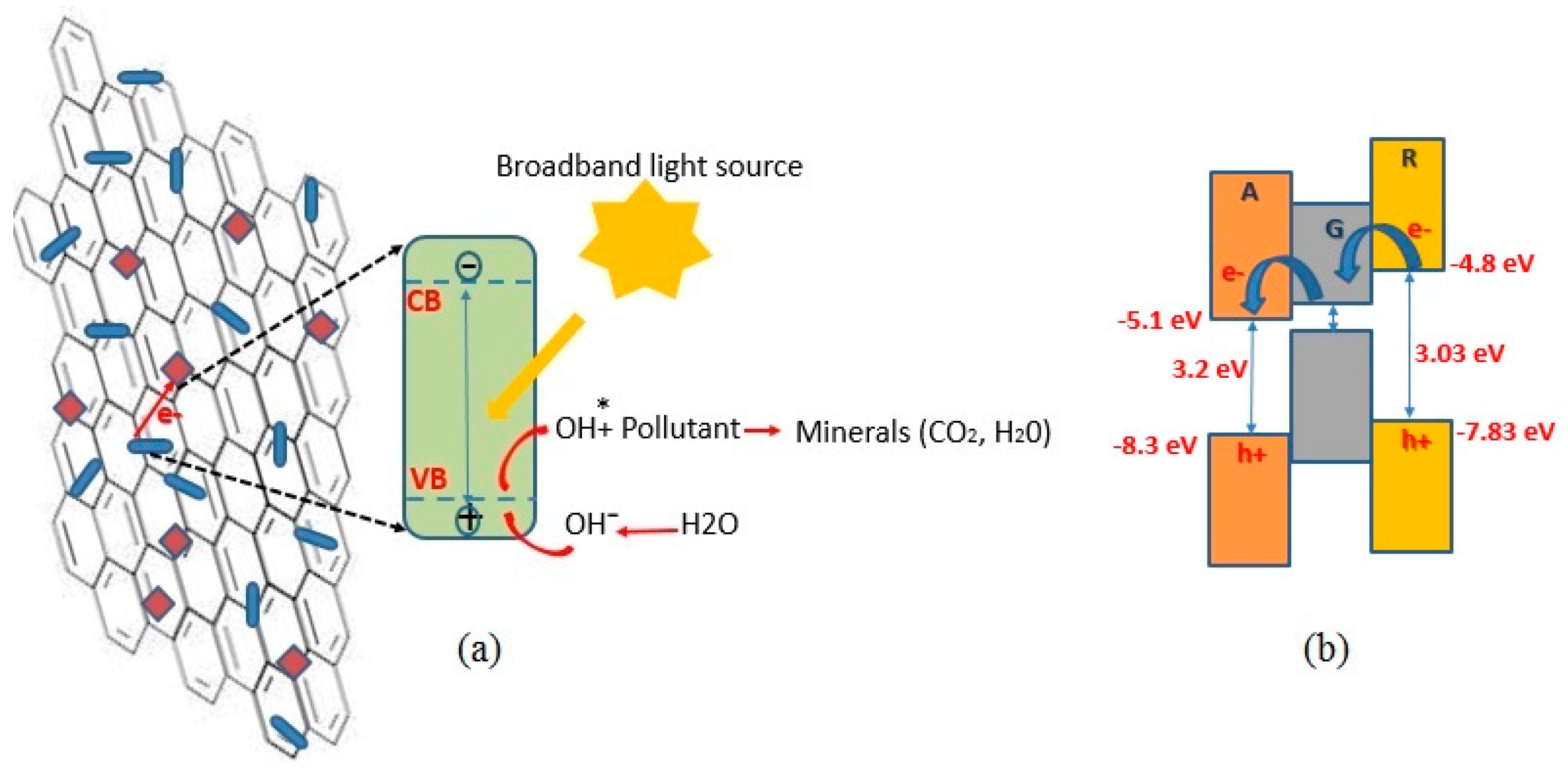
2 is a large band gap semiconductor that absorbs high energy UV photons to generate electron and hole pairs. As
Figure 1a depicts, the holes may react with the hydroxyl ions from the adsorbed surface water molecules to form highly reactive but neutral hydroxyl radicals. Airborne or aqueous pollutants may be readily adsorbed on the TiO
2 surface and react with these hydroxyl radicals, and reduced to minerals and small molecules [
7].
The photocatalytic performance of TiO
2 depends on its crystalline form. The differences in spatial coordination and chemical bonding result in far different ionization potentials, and therefore different electrical affinities [
8,
9,
10]. Anatase is famous for its size-dependent physical properties and fast photoresponse [
6,
8]. On the other hand, rutile is more stable, and the difference between its direct and indirect band gap energies is favorably small (quasi-direct band gap) [
8]. Therefore, application of mixed phases of rutile and anatase is a more desirable state for photoreaction purposes [
3,
8]. According to the literature reports, configuration of amorphous TiO
2 to a regulated crystalline form requires Ti-O
2 cleavage at elevated temperatures [
9,
11], and this requirement raises the production cost and limits its applications. Therefore, fabrication of multiphase crystalline TiO
2 via a low temperature process is desirable but challenging. This has been achieved in this work.
Carbon-based materials may be combined with TiO
2, to alleviate the fast recombination of the excited electron-hole pairs and to serve as supporting matrix for TiO
2 [
8,
11,
12,
13]. Compared to 3D carbon materials, graphene nanosheets with 2D structure are a better alternative, in that the incorporation and entrapment of TiO
2 nanoparticles into 2D graphene nanosheets is readily achieved. In addition, graphene-TiO
2 hybrid compound, in the form of powders or thin films, enables an extended light harvesting capability, owing to Ti-O-C bonding. Also, graphene-TiO
2 interfaces provide effective charge transfer junctions, which help the injection of electrons from TiO
2 to graphene sheets leading to prolonged recombination [
7,
13,
14,
15,
16]. Beside coordination with inorganic materials, graphene provides a strong chemical affinity with organic materials, in particular with the organic dyes [
17].
Figure 1b illustrates the band gap alignment of graphene-TiO
2 hybrid thin films. Recent electron paramagnetic resonance analyses ascertain that the electrical band alignment of rutile/anatase bi-morph allows electrons to flow from rutile into anatase [
8]. This is ascribed to the work function offset, placing the conduction band of anatase about 0.3 eV more negative relative to that of rutile. The work function of few-layered graphene (~−5.0 eV) lies between the conduction bands of rutile and anatase. Therefore, a graphene lattice accommodated between rutile and anatase phases favorably serves as an electron shuttle, prolonging charge recombination. On the other hand, the valence band of graphene stands much higher than those of anatase and rutile, inhibiting unwanted hole transfer, thus favoring photocatalytic function of the composite graphene-TiO
2 structure.
The oxidative nature of the composite photocatalyst will be discounted, if the TiO
2 nanoparticles are agglomerated or improperly dispersed in the graphene matrix. To alleviate this complication, several strategies have been suggested, such as using TiO
2 nanowires instead of nanoparticles [
7], and using layer-by-layer assembly of TiO
2 and graphene nanosheets [
13]. In a study conducted by Cheng et al. [
14], graphene-TiO
2 composite was synthesized by solvothermal reaction, using various graphene to TiO
2 ratios. Rahimi et al. [
15] studied the role of graphene content on light absorption and photoactivity of graphene-TiO
2 blend made by solvothermal method. Xia et al. [
3] used chemisorption assembly in which titanium (IV) isopropoxide (TIP) was added to functionalized graphene oxide suspension, followed by an intensive thermal treatment. In another study, incorporation of TiO
2 nanoparticles into graphene sheets was conducted by electrospinning [
16]. Posa et al. [
18] used graphene oxide and titanium isopropoxide to grow anatase on reduced graphene oxide nanosheets. Chemisorption was carried out in an acid-catalyzed sol-gel process which resulted in graphene oxide-TiO
2, demonstrating superior photocatalytic response. In a recent work by Hu et al. [
19], graphene-TiO
2 thin films were synthesized by electrostatical self-assembly of graphene oxide on a cellulose-TiO
2 film under an annealing temperature of 500 °C. Gopalakrishnan et al. [
20] reported in-situ solvothermal preparation of graphene-TiO
2 nanocomposite powder and its photocatalytic activity.
The abovementioned representative works show the great potential of graphene-TiO
2 for photocatalytic applications. Issues such as the presence of toxic hydrazine in the solvothermal method, the high-temperature processing required for crystallization of TiO
2, and the development and application of low-cost and scalable manufacturing methods have yet to be addressed. In this work, to obtain functional graphene-TiO
2 photocatalysts at low temperatures, we employ the sol-gel route, combined with ultrasonic substrate vibration-assisted spray [
21] and spin [
22] coating methods. Ultrasonic substrate-vibration-assisted spray coating (SVASC) [
21] is a novel and more controllable version of spray coating, which can be used to manufacture films with large areas in a low-cost industrial process. The employed method has resulted in intact, uniform, and high quality graphene thin films, e.g., [
23,
24]. Moreover, uniform and high performance spun-on functional thin films, such as polymers, perovskite and graphene-polymer hybrid, subjected to ultrasonic substrate vibration post treatment (SVPT) have been previously developed [
22,
25,
26]. Based on the hydrodynamic and instability analysis of thin liquid solution films subjected to ultrasonic vibration, Rahimzadeh and Eslamian [
27] concluded that the imposed vibration has a destabilizing effect on the liquid film. However, if the vibration power and amplitude are kept low, the destabilizing effect is moderate or insignificant; therefore, if the liquid film can resist the destabilizing effect of vibration and remains intact, the circulating motion or microstreaming created within the film as a result of the imposed vibration will actually stir and mix the precursors, a process that results in preparation of uniform and homogenized composite thin solid films, after solvent evaporation. This simple mechanical technique is therefore able to replace some tedious and energy intensive chemical and thermal treatments traditionally used for the fabrication of thin films. In this work, we prepare graphene-TiO
2 composite thin films, where both anatase and rutile coexist, using a sol-gel chemical route assisted with ultrasonic vibration, in which we show that vibration significantly reduces the required heat treatment temperature. We will elaborate later on the fact that the imposed ultrasonic vibration on the wet films assists the chemical conversion in the sol-gel process as well. In the following sections, the physical and optoelectronic and photocatalytic performance of the developed graphene-TiO
2 thin films are presented and discussed.
2. Results and Discussion
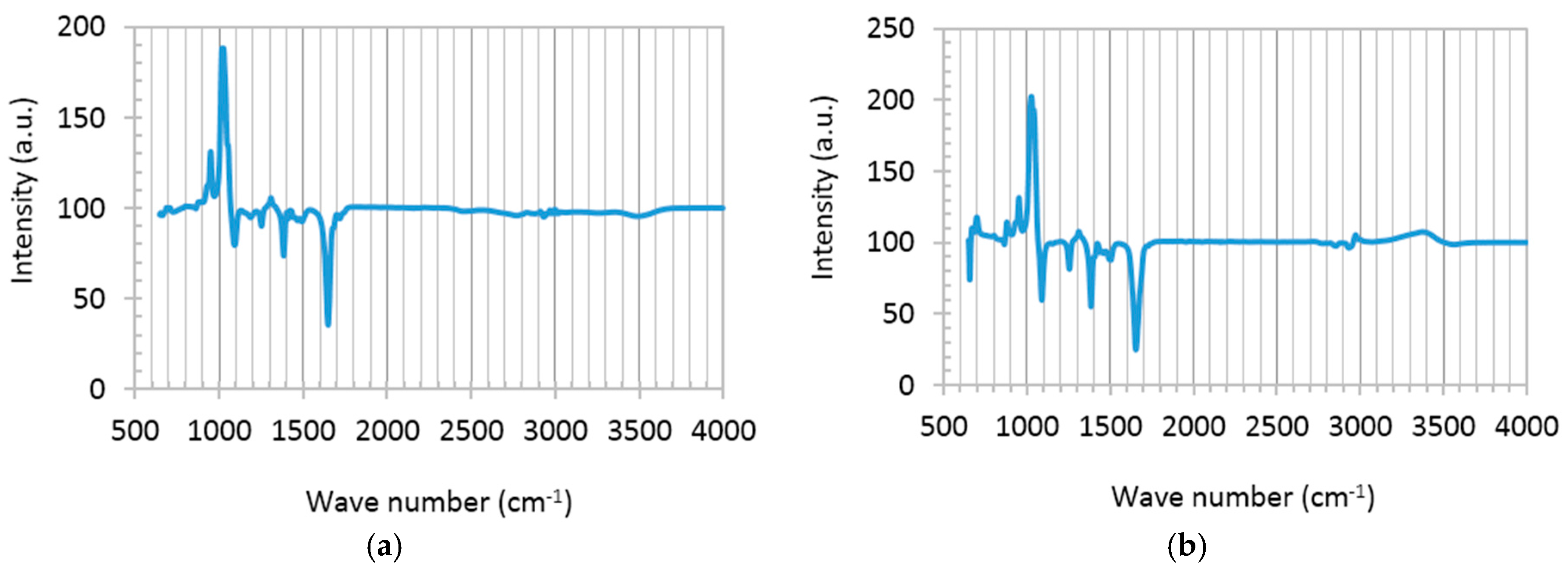
Chemical composition of graphene disperse (GD) and a mixture of GD and the TiO
2 precursor solution (titanium isopropoxide bis(acetylacetonate) solution), abbreviated as TS, was studied using liquid-phase Fourier transform infrared spectroscopy (FTIR), shown in
Figure 2. Typical graphene features appearing in both spectra are as follows: superimposed sharp peaks at 950–1100 cm
−1 reflect C-O stretching on graphene surface, due to the presence of a small percentage of oxygen in the graphene used in this study. The bold signals at 1250, 1327 and 1385 cm
−1 represent shifted C-O-C, C-O···H or C-O bindings, and imply interlinking of unsaturated –C and –OH groups in alcohols [
28]. Signals at 1430, 1507 and 1580 cm
−1 are related to bending vibration of H-C-H and C=O, perhaps formed during the long term dispersion of graphene in dimethylformamide (DMF). The weak reflection at 3450 cm
−1 shows –OH stretching due to the hydroxyl groups attached to graphene planes [
17,
28]. The FTIR spectrum of the TS:GD solution presents some additional peaks (
Figure 2b). Ti-O vibration is identified at 670 cm
−1. The left shoulder absorption band at 807 cm
−1 and the minor peaks around 2800–3100 cm
−1 are consistent with Ti-O-C binding, showing the chemisorption between TS and GD solutions [
15,
28]. The same peaks (2800–3100 cm
−1) may be attributed to metal (in this case, Ti) and methyl groups (Ti-CH
x), as well [
29].
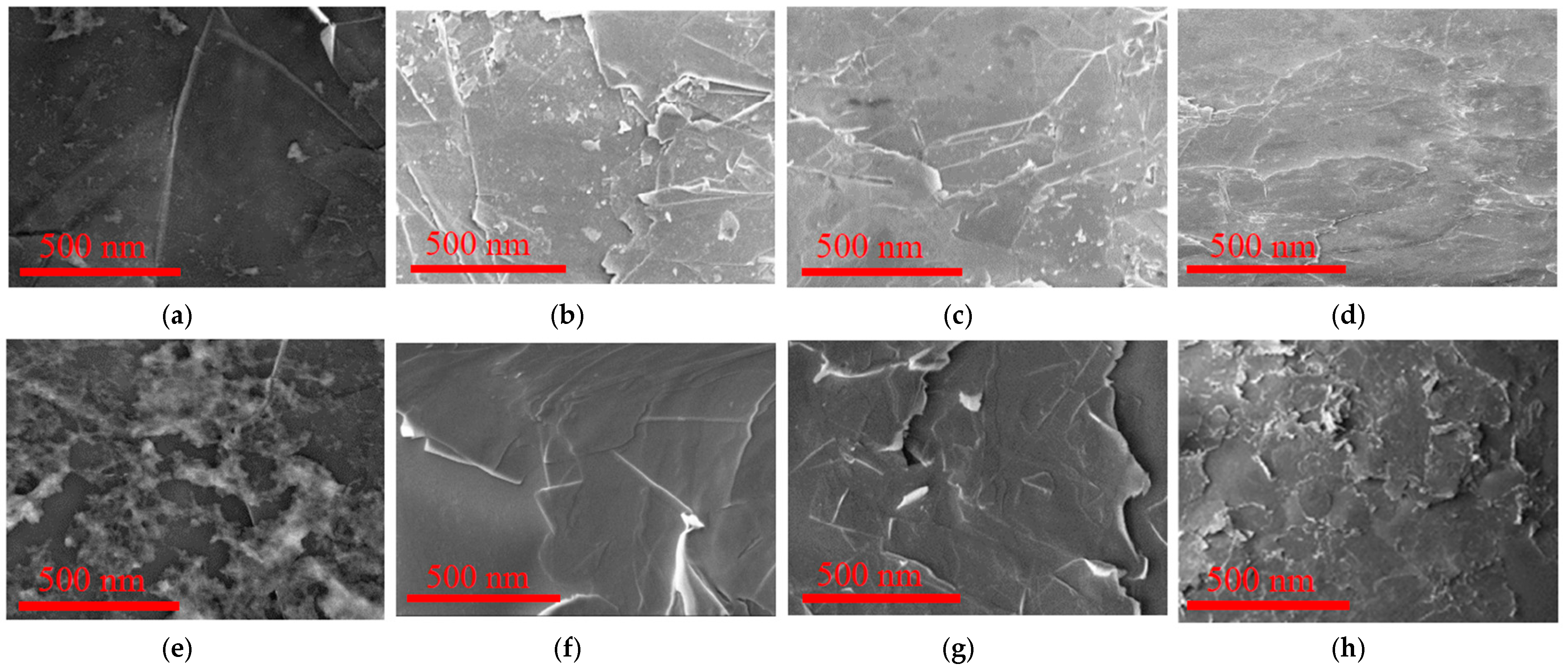
Figure 3 shows scanning electron microscope (SEM) images of the surface morphology of graphene and graphene-TiO
2 thin films made using spin-SVPT, and SVASC. The effect of the volume ratio of TS:GD solutions and annealing temperature is also investigated.
Figure 3 evidences the improving role of TiO
2 content in surface topography and therefore quality of the composite thin films, in that a higher fraction of TiO
2 in graphene-TiO
2 films results in better uniformity, owing to the reinforcing effect of TiO
2 in graphene matrix. Moreover, at identical precursor solutions and annealing temperatures, application of SVASC results in the formation of slightly more uniform films compared to spin-SVPT (images (c) vs. (d), and (g) vs. (h)), perhaps due to the detrimental effect of centrifugal forces of spin coating applied to graphene nanosheets and the titanium gel. Comparison of the upper and lower panels of
Figure 3 reveals that annealing at moderate temperature of 150 °C compared to high temperature of 450 °C results in a more uniform and intact structure, owing to gradual drying and reduced thermal stresses. The surface wrinkles are attributed to the flexible nature of graphene-TiO
2 thin films [
3,
11]. To further demonstrate the remarkable effect of the imposed ultrasonic vibration, in
Figure S1 we have shown the SEM images of selected thin films prepared without substrate vibration, i.e., by conventional spin and spray coating, where the non-uniform surface of the films are evidenced.
Figure S2 shows the effect of the temperature and TiO
2 content on graphene-TiO
2 film thickness (~10–50 nm). An increase in the TS to GD volume ratio results in a decrease in the film thickness. This may be attributed to the higher density of TiO
2 compared to graphene. It is observed that the films annealed at 150 °C are thinner than those annealed at 450 °C. This is because at lower temperatures, the solvent vapor diffuses away from the wet film more effectively, leaving behind a denser film with less voids. A high temperature may result in fast drying of the film surface and entrapment of the moisture within the film, leading to a thicker and porous film.
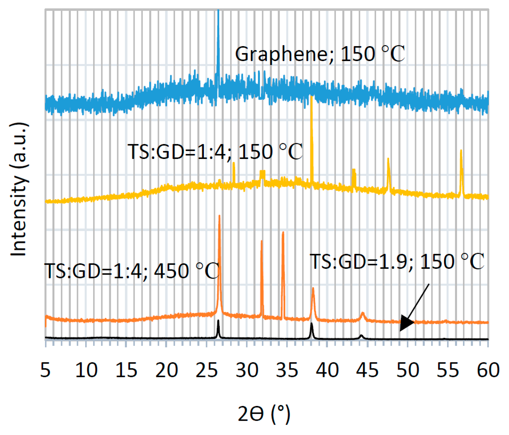
Figure 4 displays the X-ray diffraction (XRD) patterns of graphene and graphene-TiO
2 thin films. Four selected samples are compared to elucidate the effect of the annealing temperature and precursor composition on the crystalline structure of the ensuing thin films. The typical XRD of graphene is comprised of a wide background with a sharp peak at 26.6° [
23,
24,
30,
31]. This sharp signal is present in all graphene-TiO
2 spectra, except for one case, i.e., the composite thin film prepared using the precursor solution of TS:GD = 1:4 (lowest graphene content) and annealed at 150 °C, which implies homogenous dispersion of graphene nanosheets [
6]. It is found that the abovementioned conditions lead to the same XRD patterns independent of the casting method (spin-SVPT or SVASC). The signals at 31.8° and 34.6° represent the graphene oxide and graphene hydroxide perhaps formed during dispersion in organic and oxidative media [
2,
3,
18]. These unwanted bindings deteriorate the optoelectronic performance of the graphene-TiO
2 thin films. Nevertheless, these two peaks only appear in XRD patterns of the samples annealed at 450 °C. The peak at 36.4 °, assigned to 004 anatase and 101 rutile planes, appear in TiO
2-rich samples and is intensified when the film is annealed at 150 °C. The peaks at 44.7°, associated with the 105 plane of anatase is present in all composite films, but is weak and slightly shifted in the films with low TiO
2 content and annealed at 450 °C [
18]. The other peak at 45.4° is due to 211 anatase plane and appears when the film is deposited from the solution with TS:GD of 1:4 and annealed at 150 °C [
18]. The reflection peak at 56.6° is assigned to 211 anatase and 105 rutile planes [
3,
13,
15]. These signals are weak in the composite films with low TiO
2 content, but are quite strong in the TiO
2-rich film annealed at 150 °C. Another signature of TiO
2, 200 anatase plane at 48° only appears in the rich-TiO
2 film annealed at 150°C. Therefore, a TiO
2-rich composite film annealed at 150 °C shows ideal transformation of titanium precursors to crystalline TiO
2. It is deduced that the imposed ultrasonic vibration has significantly reduced the required annealing temperature to achieve desired crystalline TiO
2 film. The explicit peaks of the rutile and anatase TiO
2 phases in XRD patterns indicate that TiO
2 was physically combined with the graphene lattice, and no chemical binding has occurred between graphene and TiO
2.
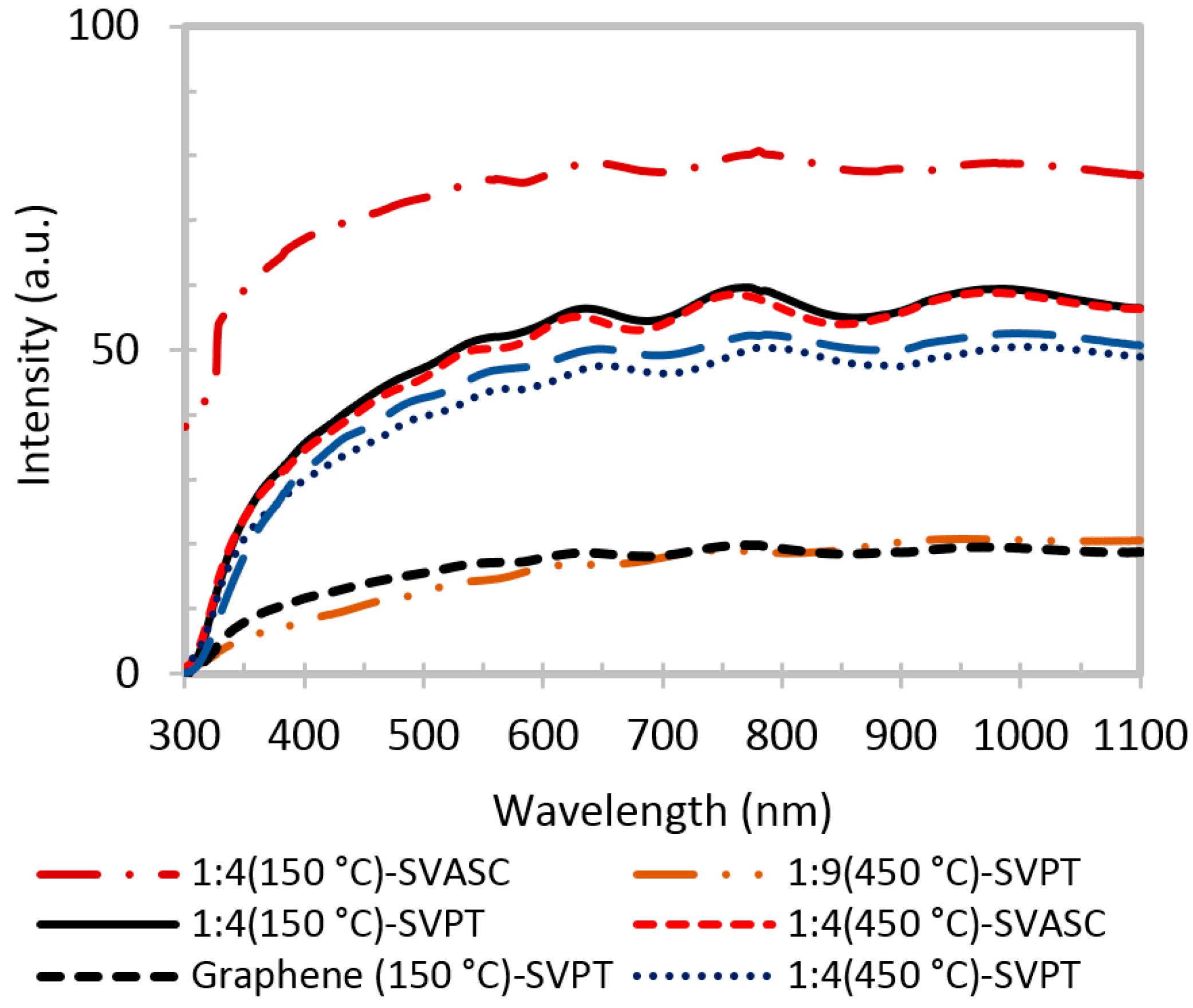
The transmittance spectra of graphene and graphene-TiO
2 thin films are presented in
Figure 5. In general, it is evidenced that the films with higher TiO
2 content, deposited by SVASC, and annealed at 150 °C are more transparent. TiO
2 is unable to absorb the photons in the visible range, due to its large band gap. Thus, it is expected that a higher TiO
2 content in the thin film results in better transparency in the visible range [
3,
11]. The films annealed at 450 °C show low transparency, presumably due to their larger thickness, as shown in
Figure S2, and the defective porous structure. The SVASC films show a relatively better transmittance, compared to spin-SVPT films, perhaps due to the destructive effect of the centrifugal forces that may cause detachment of titanium in the form of hydrogels from the graphene network in the wet films. Therefore, even when deposited from the same precursor solution, the spray-on thin films contain larger amount of TiO
2, thus showing higher transparency in the visible range.
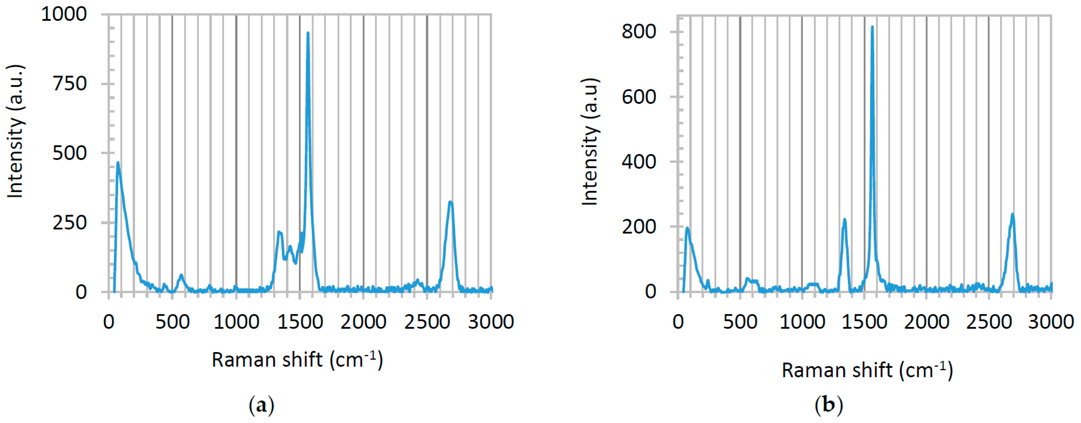
Raman spectra of graphene-TiO
2 thin films present various patterns depending on the annealing temperature and the casting method. Here, we only display the Raman spectra of the film fabricated using precursor solution with TS:GD volume ratio of 1:4, fabricated by spin-SVPT and SVASC, and annealed at 150 °C (
Figure 6). The Raman spectra of the films fabricated using the same precursor solution, but annealed at 450 °C are presented in
Figure S3 of the Supporting Information. Raman spectra of the films deposited from the solution with TS:GD volume ratio of 1:9 showed no clear TiO
2 peaks, due to the low content of TiO
2 in the composite films and high intensity of graphene bands, which obscure the TiO
2 peaks. The prominent peaks at 1570 cm
−1 (G), 2700 cm
−1 (G’: the unique feature of few-layered graphene) and the weak peak at 1350 cm
−1 (D) are graphene reflections [
23,
24,
32,
33,
34]. The sharp and symmetric graphene peaks indicate the small size, few-layered, nanoscale and homogenous form of graphene sheets [
33,
34,
35]. We attribute the formation of this favorable structure to ultrasonic vibration, which homogenizes the film nanostructure. Another evidence of the smaller, few-layered configuration of graphene is the high intensity ratio of D to G peaks (
ID/
IG > 0.23). Small values of
ID/
IG (<0.2) suggest the presence of large graphite segments in the domain [
34,
35,
36,
37]. According to the Raman spectra of
Figure 6, in both SVPT and SVASC films this value is above 0.24. The signals appearing between the graphene peaks are related to different TiO
2 phases. Both spectra of
Figure 6 demonstrate the known 440 cm
−1 vibrational band of rutile and the 391 cm
−1 band of anatase phases. The known peaks at 144 and 236 cm
−1 associated with rutile have been combined and circumvented by a wide peak at the left shoulder of the Raman spectra. The other known vibrational bands of rutile at 580, 613 and 769 cm
−1 and conjugated signals of anatase at 520–640 cm
−1 [
1,
10,
11,
12] are somewhat detected, although the TiO
2 peaks are weak, due to the strong peaks of graphene. It is noted that in
Figure 6 there is no footprint of amorphous TiO
2 in the samples annealed at 150 °C. Moreover, in both cases rutile is the dominant phase, which is chemically and thermodynamically stable and is a stronger charge carrier with lower band gap compared to anatase [
3,
9,
10]. It is also deduced that the high temperature processing at 450 °C disrupts the Raman peaks of graphene (
Figure S3), as discussed before. Amorphous TiO
2 has reflections at 1061, 1100 and 1342 cm
−1 [
9,
10,
12], and
Figure S3a clearly shows the peaks at 1100 and 1342 cm
−1, substantiating that the films annealed at 450 °C contain amorphous TiO
2 phase.
According to the discussed XRD and Raman spectroscopy results, the ultrasonic vibration-assisted sol-gel followed by spin or spray coating and a mild heat treatment results in the formation of anatase/rutile polymorph. As substantiated in our previous works [
21,
25,
26] and observed in our ongoing studies, a very striking effect of the excitation by ultrasonic vibration is its controlling effect for preferential orientation of crystallization (nucleation and growth), and a decrease in the activation energy of crystallization, leading to the formation of crystalline phases of titanium at a lower temperature.
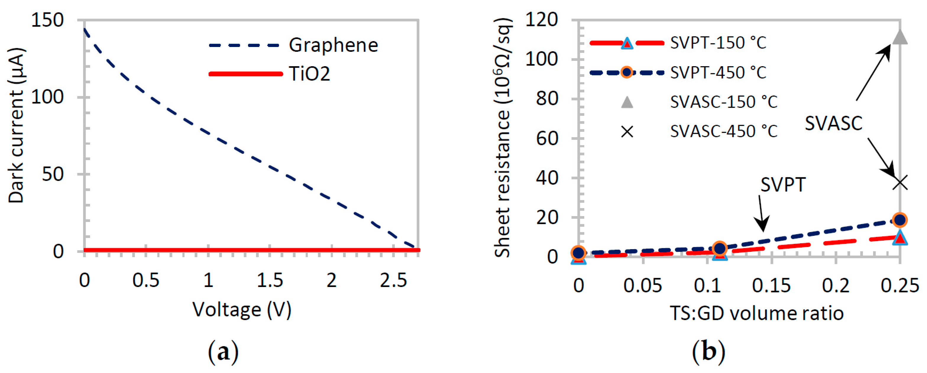
The dark current-voltage (I-V) and sheet resistance curves are affected by the presence of TiO
2 in graphene-TiO
2 thin films [
2,
38], because TiO
2 behaves as an insulator in the dark. The I-V curves shown in
Figure 7a confirm that TiO
2 thin film creates no current in the dark, whereas graphene thin film is highly conductive. The Hall measurements of
Figure 7b show that the sheet resistance of graphene-TiO
2 increases by increasing the TiO
2 content, as expected. The sheet resistance also increases in the films annealed at 450 °C, due to the formation of defects and voids in the film structure as a result of rapid drying, as discussed before. However, due to the synergic light-reactive function of TiO
2 and graphene, a different optoelectronic behavior is observed when the films are exposed to broadband illumination.
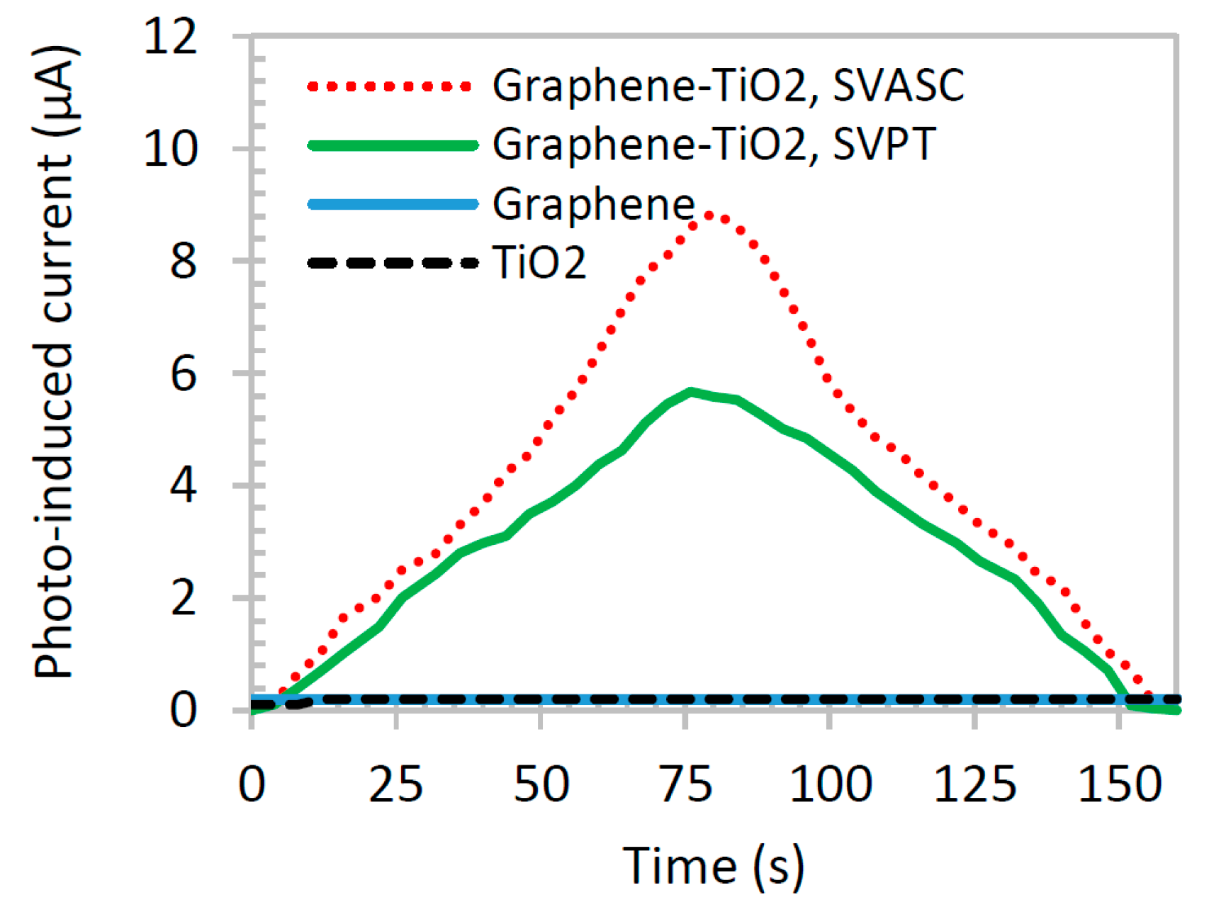
Figure 8 shows the photoinduced current of graphene-TiO
2 thin films compared with those of pristine TiO
2 and graphene thin films. The illumination source was blocked after about 80 s. TiO
2 and graphene films show negligible photoinduced current response, individually (overlapped in the x axis of the graph), whereas graphene-TiO
2 films demonstrate a good synergic photocurrent generation. The SP
2 barrier effect of –O and –OH groups in graphene networks may be responsible for its negligible photocurrent activity [
39]. Also, the large band gap and extremely short lifetime of excitons in TiO
2 result in poor photoinduced current. On the other hand, when combined in the form of graphene-TiO
2 thin film with a well-structured architecture, the composite film benefits from the high photoinduced charge dissociation of TiO
2 at the presence of graphene, increased absorption range, particularly at Ti-O-C bonds, and prolonged recombination provided by graphene. The larger photoinduced responses of the thin films fabricated by SVASC are consistent with the aforementioned characterization results, i.e., the improved structural arrangement and the good uniformity and higher content of TiO
2 in spray-on thin films, compared to those of the spun-on thin films.
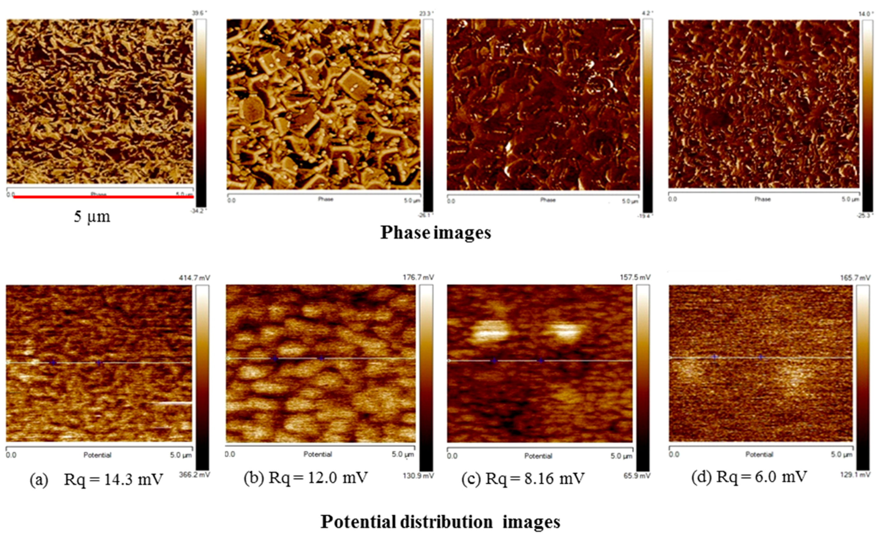
We also investigated the distribution of surface potential and phase images by atomic force microscopy (AFM) (
Figure 9). The potential roughness (
Rq) indicates the deviation in distribution of the surface potential.
Figure 9 shows that an increase in the TiO
2 content results in a decrease in
Rq, because as shown in SEM images of
Figure 3 and AFM phase images of
Figure 9, the addition and increase of the TiO
2 content has a positive effect on the surface uniformity and structural homogeneity. The potential roughness of the spin-SVPT graphene film decreases from 14.3 to 12 mV by adding a small amount of TiO
2 (TS:GD volume ratio of 1:9). A further increase in the TiO
2 content (TS:GD volume ratio of 1:4) results in further reduction of potential roughness to 8.16 mV. With the same precursor solution, the SVASC film shows the lowest potential roughness of 6 mV. The potential profiles and the peak-to-valley roughness values along the lines shown on the potential maps are displayed in
Figure S4 of the Supplementary Materials. The variation of peak-to-valley roughness is consistent with the
Rq roughness of
Figure 9. The size of the graphene nanosheets and TiO
2 particles (bright spots) can be inferred from some of the AFM phase images.
The contact angle of water droplets on graphene and graphene-TiO
2 films are shown in
Figure S5, where it is found that graphene-TiO
2 film is highly wetting (small contact angle) and therefore superhydrophilic. This is due to the hydrogen bonding and strong interlinking between Ti–O and unsaturated –O and –OH groups on graphene [
12,
40,
41,
42]. It is known that TiO
2 surface is self-cleaning, meaning that it removes the surface dirt, such as organic compounds. This may be related to superhydrophilicity and/or photocatalysis capability of TiO
2 surface [
43]. Here we show that the graphene-TiO
2 film has a similar capability.
To test the photocatalytic activity of graphene-TiO
2 thin films, the best graphene-TiO
2 films (spin-SVPT and SVASC, deposited from the solution with TS:GD volume ratio of 1:4 and annealed at 150 °C) in terms of functionality, composition and uniformity, as well as pristine TiO
2 and graphene thin films, were subjected to photodegradation analysis.
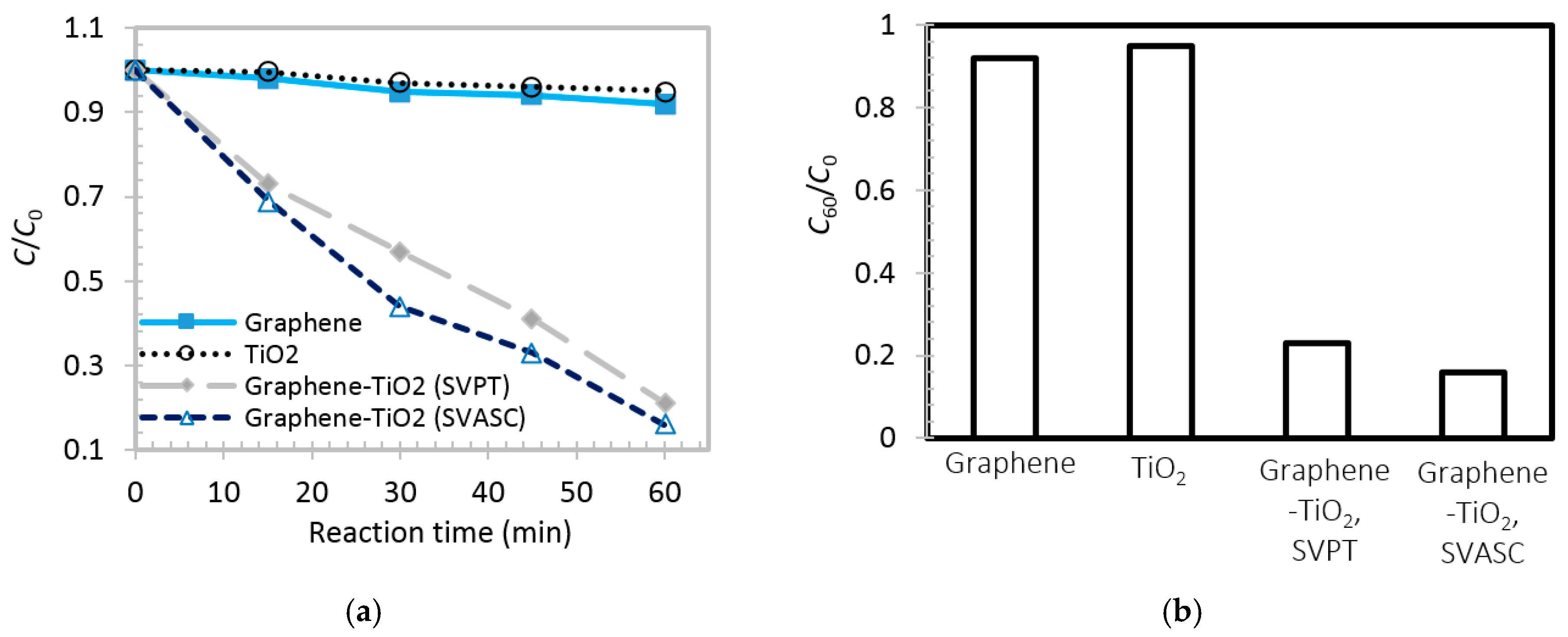
Figure 10a,b show the time-varying and maximum degradation performance (after 60 min) of the abovementioned films, respectively. The TiO
2 thin film shows a poor photodegradation of MB in water, less than 8% after 60 min. This low photocatalytic performance may be attributed to the fast charge recombination [
44,
45]. Graphene thin film also shows a poor involvement in chemical conversion, as observed by others also, e.g., [
46], here about 5% after 60 min. In the case of graphene-TiO
2 thin films, it is observed that under illumination, the spin-SVPT and SVASC samples linearly degrade the contaminant, and after 60 min about 77% and 84% of MB in water is removed, respectively. In graphene-TiO
2 thin films, the photoinduced carriers from TiO
2 are conducted within the graphene network, leading to longer carrier lifetime. Moreover, the increased photoconversion might be due to better trapping of the contaminants, owing to the large surface area of the 2D structure of graphene, and the unsaturated functional groups on graphene sheets [
7,
19]. The photoconversion performance and degradation rates observed in
Figure 10 are consistent with photoinduced current results of
Figure 8. It is worth noting that the obtained photoinduced reaction rates of the composite films are comparable with few similar works available in the literature [
3,
7,
18], but in the present study, the films contain both TiO
2 phases and are fabricated using scalable and facile spray coating at much reduced annealing temperatures, achieved by ultrasonic vibration.
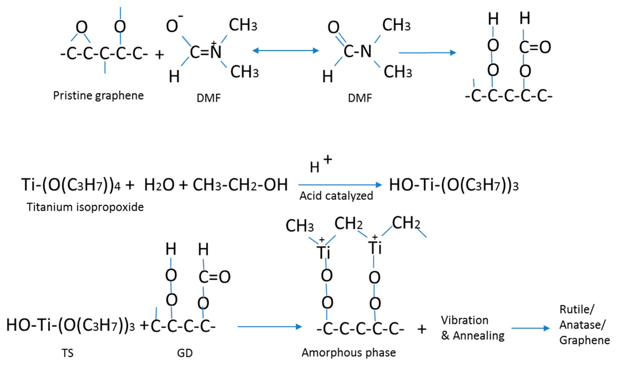
Figure 11 shows the coordination of graphene with a small amount of oxygen with DMF, reaction of titanium precursor with ethanol and water under acid catalyzing by HCl, and a suggested route for the sol-gel conversion process and transformation of the amorphous TiO
2 to crystalline TiO
2. In this process, it is speculated that the –OH groups for the formation of the gel phase in the hydrolysis step of the sol-gel process is supplied by ethanol, as well as water. The ultrasonic vibration and a mild heat treatment convert the titanium gel into crystalline TiO
2. It is deduced and supported by the characterization results that the imposed ultrasonic vibration helps disruption of the gel phase, and therefore a lower annealing temperature is required to remove the residuals to convert the titanium precursors to TiO
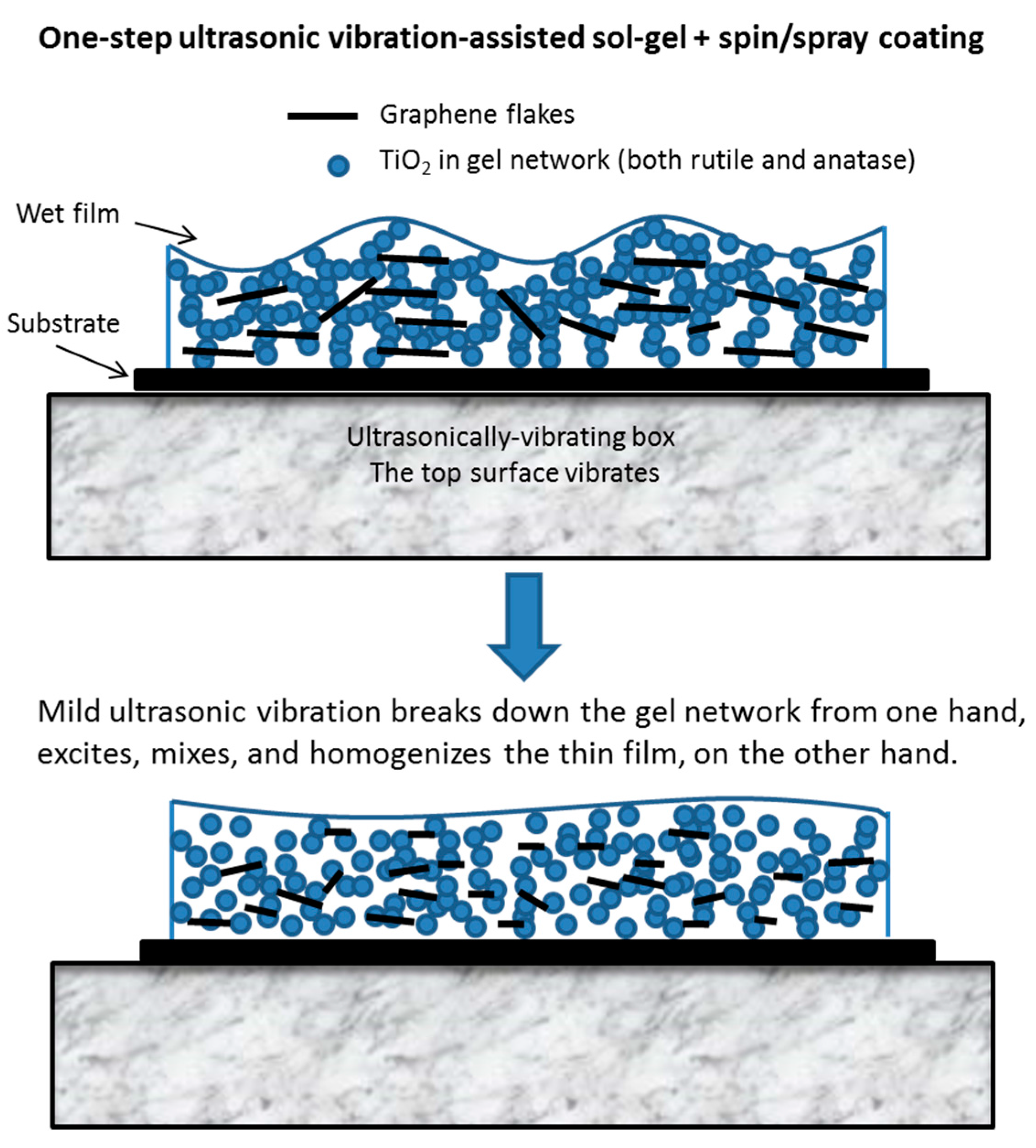
2.
Figure 12 illustrates the abovementioned explanation. It is noted that in this work, ultrasonic vibration is used to assist the sol-gel conversion process, as well as to assist the formation of a uniform composite film, in one fabrication step. Ultrasonic vibration has been used by others to boost the chemical conversion, e.g., powder synthesis by sol-gel [
47] and hydrothermal [
48] processes, but not thin films.
3. Materials and Methods
Few-layered graphene nano-sheets (FLGNS, 3 stacked layers, 1 nm average thickness of each layer with 1.5% oxygen content, and average surface area of 1960 m2/g) were provided by Hengqiu Graphene Technology Co., Ltd., Suzhou, China. HCl aqueous solution (36.5%), dimethylformamide (DMF, 99.5%), ethanol (99.5%), 2-propanol (99.8%), acetone (99.5%) and titanium isopropoxide bis(acetylacetonate) (75% in 2-propanol) were purchased from Sigma-Aldrich, St. Louis, MO, USA. Bare glass and indium-doped tin oxide (ITO)-coated glass substrates (1.5 cm × 1.5 cm) were purchased from Nanbo Display Technology, Shenzhen, China.
The glass substrates were washed in an ultrasonic bath using detergent, 2-propanol, and deionized water, sequentially, for 30 min and dried in a vacuum oven and placed in an ultraviolet cleaner for 12 min. Precursor solution of graphene-TiO
2 thin films was composed of titanium isopropoxide bis(acetylacetonate) solution (TS) and graphene disperse (GD) mixed with TS:GD volume ratios of 1:4 and 1:9. For preparation of GD, 50 mg of graphene nanosheets was added to 10 mL of DMF, supersonicated for 6 h, and agitated overnight on a magnetic stirrer. For preparation of TS, 35 µL of HCl solution mixed with ethanol (1:50 volume ratio, respectively) was gradually added to diluted titanium isopropoxide bis(acetylacetonate) (0.07 volume ratio in ethanol, stirred for 10 min) and the mixture was stirred for 30 min. The GD and TS solutions were then mixed, sonicated for 6 h and stirred overnight before casting. The TS precursor solution was converted into TiO
2 in a sol-gel process. The graphene-TiO
2 composite thin films were deposited by spin coating followed by ultrasonic substrate vibration post treatment, called spin-SVPT or simply SVPT and ultrasonic substrate vibration-assisted spray coating (SVASC).
Table S1 in the Supporting Information lists the experimental conditions. In the case of SVASC, the substrate is ultrasonically vibrated by placing it on a vibrating metal box. A piezoelectric ceramic (5 W and 40 kHz) is mounted inside the top surface of the metal box, which vibrates the substrate in the vertical direction. SVASC was performed using an air-assist spray nozzle mounted on a 3D traverser arm. Back pressure of the atomizing air was set to 0.3 MPa and the distance between the nozzle tip and the substrate was kept constant at 80 mm. Nozzle speed, spray flow rate and number of spray passes were set to 10 mm/s, 200 µL/min, and single spray pass, respectively. In spin-SVPT experiments, the precursor solution was spun at 2000 rpm for 60 s. The as-spun wet films were immediately placed on the surface of the vibrating box for 10 s. As-sprayed and as-spun wet thin films were annealed at 150 or 450 °C, for 45 min. TiO
2 forms in a sol-gel process assisted by energy impartment to the solution by ultrasonic vibration, and is completed by removal of the solvents after heat treatment (c.f.
Figure 11 and
Figure 12).
The intermolecular bindings in composite films were characterized using Raman spectroscopy (Horiba Jobin Yvon LabRam model HR800, Horiba Scientific, Kyoto, Japan). The Raman spectra were recorded at room temperature with a micro-Raman system equipped with a CCD camera, using 514 nm laser line, under attenuated power of 5 mW. Raman shifts were calibrated at 521 cm−1. Liquid phase Fourier transmission infrared spectroscopy (FTIR) was performed on the precursor solutions, using a Smart iTR accessory connected to a Nicolet 6700 FTIR spectrometer (Thermo Fisher Scientific, Waltham, MA, USA). DMF:ethanol:HCl mixture (10:2:1 volume ratio) was used as the background medium. The transmission UV-vis spectra of the thin films were recorded using a Shimadzu UV-3101PC UV-Vis-NIR spectrophotometer, Shimadzu, Kyoto, Japan. Samples were prepared on bare glass and a second bare glass was used as the background. Surface morphology of the thin films was studied by scanning electron microscopy (SEM, Hitachi, Model S-3400 N, Tokyo, Japan). The local surface potential and the phase images were obtained by atomic force microscopy (AFM, Dimension Icon & FastScan Bio, Brucker, Bremen, Germany), while the thin films were deposited on ITO-coated glass. Surface potential was determined based on the local differences of the electrical potential between the sample and a Cr/Pt coated conductive tip (Multi75E-G, BudgetSensors, Sofia, Bulgaria) at constant force of 3 N/m, positioned at 2 μm distance from the surface. Electrical resistivity of thin films was obtained using a Hall measurement instrument (MMR Technologies, San Jose, CA, USA), at room temperature, based on the van der Pauw four-point method. The samples were cast on bare glass. X-ray diffraction (XRD) patterns of the films fabricated on bare glass were obtained using XRD spectroscopy (XPert3 MRD (XL), PANalytical, Westborough, MA, USA). The surface profilometery (KLA-Tencor P7, Milpitas, CA, USA) was used for thickness measurements. The dark current-to-voltage trend and the photoresponse under illumination were measured in a standard probe station, using a Keithley source meter Model 2602A, Gorinchem, The Netherlands. The broadband irradiation was generated using a solar simulator Xenon lamp with an intensity of 100 mW·cm−2. Equilibrium contact angles of a 20 μL deionized water droplet were measured using a Theta Lite Optical Tensiometer, Biolin Scientific AB, Gothenburg, Sweden. Photocatalytic performance of the thin films was evaluated based on photodegradation of methylene blue (MB) in water under broadband illumination. For each measurement, 1 mL of MB solution (2 ppm in deionized water) was dispensed on the thin films and the films were placed under a Xenon lamp (100 mW·cm−2). The distance between the light source and sample was set to 5 cm in all experiments and 50 µL of reaction fluid was used in 15 min time intervals, to study the time-resolved catalytic performance, in 60 min. Concentration of MB in water was measured by UV-vis absorption at 663 nm.


