Theoretical Study on the Quantum Capacitance Origin of Graphene Cathodes in Lithium Ion Capacitors

1
CAS Key Laboratory of Carbon Materials, Institute of Coal Chemistry, Chinese Academy of Sciences, Taiyuan 030001, Shanxi, China
2
College of Materials Science and Engineering, Taiyuan University of Technology, Taiyuan 030001, Shanxi, China
*
Author to whom correspondence should be addressed.
Catalysts 2018, 8(10), 444; https://doi.org/10.3390/catal8100444
Submission received: 4 September 2018
/
Revised: 30 September 2018
/
Accepted: 3 October 2018
/
Published: 11 October 2018
(This article belongs to the Special Issue Heterogeneous Catalysis for Energy Conversion)
Abstract
:Quantum capacitance (QC) is a very important character of the graphene cathode in lithium ion capacitors (LIC), which is a novel kind of electrochemical energy conversion and storage device. However, the QC electronic origin of the graphene cathode, which will affect the electrochemical reaction at the electrode/electrolyte interface, is still unclear. In this article, the QC of various kinds of graphene cathode is investigated systematically by DFT calculation. It was found that the value and origin of QC strongly depend on the defects and alien atoms of graphene. Graphene with pentagon defects possesses a higher QC than pristine graphene due to the contribution from the electronic states localized at the carbon pentagon. The introduction of graphitic B can contribute to QC, while graphitic N and P does not work in the voltage range of the LIC cathode. Single vacant defect graphene and pyrrolic N-doped graphene demonstrate very high QC due to the presence of states associated with the σ orbital of unbonded carbon atoms. However, pyridinic graphene shows an even higher QC because of the states from the N atom. For the residual O in graphene, its QC mainly originated from the pz states of carbon atoms and the effect of O, especially the O in bridged oxygen functional group (–COC–), is very limited. These results provide new insight into further study of the catalytic behavior and the design of a high performance graphene cathode for LIC.
1. Introduction
Lithium ion capacitor (LIC) is a kind of hybrid electrochemical energy conversion and storage device typically consisting of a capacitive cathode and an intercalated anode. The capacitive cathode can bring excellent rate performance, while the intercalated anode enhances its capacity. Therefore, LICs possess high power and high energy density simultaneously and can fill the gap between the lithium ion battery and a supercapacitor. Activated carbon is used as the cathode [1], while the negative electrode is mainly composed of graphite [2,3,4,5], hard carbon [6,7], lithium titanate [8], etc. A capacitive cathode uses ion adsorption to store energy. The larger specific surface area means higher specific capacity and higher energy density. At the same time, the electronic conductivity of the electrode should be high to suppress the ohmic resistance when the LIC is charged/discharged at a high current rate. Therefore, the capacitive cathode of the LIC should possesses both a high specific surface area and good electronic conductivity simultaneously. Recently, graphene has also been used as an effective novel cathode for its particularly large specific area and high electronic conductivity [9,10,11,12,13].
As for the electrical double layer formed at the interface of the graphene/electrolyte, the total capacitance, Ctot, can be theoretically divided into two parts, the capacitance from graphene (Cgraphene) and the capacitance from the electrolyte(CElectrolyte), with the following relationship:
1/Ctot = 1/Cgraphene + 1/CElectrolyte
Here, Cgraphene represents the capacitance of single layered graphene. Celectrolyte combines the Helmholtz capacitance and the diffuse capacitance. However, since the electrolyte concentration in commercial LIC is usually high (~1 mol/L), the diffuse capacitance can be excluded.
It is well known that the Cgraphene of pristine graphene is limited by the density of states (DOS) of graphene near the Fermi level, which is extremely low compared with that of metallic materials [14]. In fact, the DOS of single layered pristine graphene at the Fermi level is zero. Therefore, the capacitance is limited by DOS and is called quantum capacitance (QC), which is smaller than CElectrolyte. The QC of pristine graphene has been investigated widely by experimental and theoretical calculations [15,16,17,18,19]. It is generally accepted that QC shows a V-like shape near the zero point potential with a value less than 10 μF/cm2, depending on the applied voltage range [15,17]. Thus, according to Equation (1), the enhancement of Ctot is limited by Cgraphene. Consequently, pristine graphene is rarely introduced as a cathode in LICs. On the other hand, modified graphene materials, such as activated graphene [10], reduced graphene [9,12,20,21], and graphene networks [5,11,22], which are abundant in defects and alien atoms, are widely used.
According to the number of missing carbon atoms in graphene, there are many types of defects [23], which are shown in Figure 1. The Stone–Wales (SW) defect, in which four carbon hexagons become two pentagons and two heptagons (55-77), is the simplest case because no carbon atom is lost. When one carbon atom is lost, D1 defected graphene is formed. Due to the Jahn–Teller distortion, a new C–C bond will be formed and hence a pentagon and nonagon (5-9) will be present [24,25]. The topological structure is complex for D2 type defected graphene, in which two carbon atoms are lost. It is known that there are at least three kinds of D2 structures, 5-8-5 (D2_I), 555-777 (D2_II) and 5555-6-7777 (D2_III), whose formation energy follows the order of D2_I > D2_III > D2_II [25]. When more carbon atoms are lost, the defects can be viewed as combinations of the point defects discussed above. Other than defects, doping is also used to tailor the electronic structure of graphene. Alien atoms in these modified graphene cathodes are mostly N, because N has a similar size as the carbon atom and is easy to be introduced into the graphene lattice through various experiments. According to the C–N bonding type, there are three kinds of N in graphene: graphitic N (bonding with three C atoms in hexagon), pyrrolic N (bonding with two C atoms in pentagon) and pyridinic N (bonding with two C atoms in hexagon). At the same time, B and P atoms are also introduced in the graphene lattice. Experimental methods employed to introduce N, P and B atoms consist of pyrolysis, thermal annealing, hydrothermal and chemical vapor deposition (CVD), which have been reviewed in [26,27,28]. O atoms can also be found in reduced graphene oxide (rGO) due to its graphene oxide (GO) precursor.
Up to now, the QC of graphene with various structural defects [9,29,30,31,32] and alien doping atom [33,34,35,36,37] has been investigated in the voltage range of supercapacitors. Based on the calculation results, the QC of modified graphene strongly depends on the applied voltage range. In contrast to the supercapacitor, the bias voltage range of the graphene cathode in LICs is about 0–1.0 V [38,39], because the whole work voltage window of LICs is about 3.0–4.0 V (vs Li+/Li) or even higher. In this voltage range, we still lack a deep understanding of the required structural information of graphene for its application. Also, the effect of P, B and residual O elements on the QC of the graphene cathode is rarely investigated. The origin of the QC of those kinds of graphene materials in the voltage of the LIC cathode is still not clear. Irreversible electrolyte oxidation will be caused by the catalytic effect of carbon materials [40,41], and hence the cycle life will get worse. Higher QC may enhance the activity of the graphene cathode toward electrolyte decomposition because of the higher DOS near the Fermi level. Hence, it is very important to illustrate the electron origin of QC because it is closely related to the catalytic behavior of the graphene cathode in LIC.
To explore the surface structure and the corresponding electronic structure to promote the QC behavior of graphene materials in this voltage range, graphene with various point defects and N, P, B, O atoms were investigated by DFT calculations in this work. Firstly, graphene with the SW, D2 defect and graphitic N, P and B was studied because their bands with a high π character contribute to QC when graphene-based LIC is charged. Then the QC of the D1-defected graphene and graphene with pyrrolic N and pyridinic N were investigated to assess the effect of the bands associated with localized σ states. Finally, the effect of the residual O in the graphene was also evaluated. The results clearly illustrate the origin of graphene QC for the cathode in LIC. It is expected that the theoretical results may facilitate the design of high QC graphene materials by modifying the structure and surface chemistry.
2. Results and Discussion
2.1. Point Defects
The QC and the excessive surface charge density (ESCD) of pristine and SW, D2 defected graphene are shown in Figure 2a,b, respectively. As shown in Figure 2a, the QC of pristine graphene, which increases with voltage, reaches about 18(9.9) μF/cm2 at the voltage of 1.0(0.6) V. It can be attributed to the shape of its DOS profile in the energy range between -1 eV and the Fermi level shown in Figure 3a. Since the QC is calculated based on the fixed-band approximation, the shape of the QC plot follows that of the corresponding DOS profile. At the same time, its ESCD also increases with voltage monotonously and the peak value of 9.0(3.3) μC/cm2 can be found when voltage reaches 1.0(0.6) V. The result here is very close to previous reports [29,30,34]. The behavior of SW defected graphene is very similar to pristine graphene when voltage is below 0.6 V. Hence there is no obvious difference that can be found in the ESCD. However, when the voltage further increases, the QC of SW defected graphene becomes higher, and hence the ESCD increases accordingly. D2-I defected graphene also follows the situation of the pristine graphene when the voltage is lower, although the QC becomes smaller than that of pristine graphene when the voltage is higher than 0.7 V. Therefore, only minor differences in QC can be found among pristine, SW and D2-I defected graphene, other than very minor variations when the voltage is near 1.0 V. However, when it comes to the other two kinds of D2 defected graphene (D2_II and D2_III), the situation is totally different.
Unlike the cases of pristine, SW and D2_I defected graphene, where the QC increases in a linear fashion, the QC of D2_II and D2_III defected graphene shows multiple peaks and fluctuates following the increase of voltage. This phenomenon can also be attributed to their fluctuating DOS profile, which will be shown in Figure 3d,e. The QC of the D2_II and D2_III peak at 48.09 μF/cm2 and 41.93 μF/cm2 when voltage is 0.84 and 1.0 V, respectively. Although their QC is lower than that of pristine graphene in a certain voltage range, the ESCD of D2_II and D2_III defected graphene is much higher, being 24.77 and 15.30 μC /cm2 when the voltage reaches 1.0 V. Therefore, in order to improve the energy storage ability of LIC, the D2_II and D2_III type defect should be favored in the graphene cathode.
The QC can be attributed to the DOS near the Fermi level of different kinds of graphene. In order to illustrate the difference in QC behavior, the band structure, DOS and band-decomposed charge density (BDCD, 1.0 eV below the Fermi level) are shown in Figure 3. When graphene is used as the cathode of LIC, the electron must be extracted from the cathode when the LIC is charged. Thus, the available electron states under the Fermi level determine the energy storage ability of the electrode. SW and D2_I defected graphene showe almost the same DOS as pristine graphene in energy range between -1.0 eV and the Fermi level. Thus the QC behavior of the three kinds of graphene are nearly identical. However, due to the increase of available states shown in the DOS of D2_II (Figure 3d) and D2_III (Figure 3e) defected graphene, their QC are much higher than that of the first three kinds of graphene. The band gap can be found in D2_II and D2_III defected graphene, and hence their QC fluctuates with voltage. At the same time, the electronic states of D2_II and D2_III defected graphene are much higher than that of the previous kinds of graphene, so their QC are much higher.
The origin of the QC is another interesting issue, especially for the D2_II and D2_III defected graphene. From the BDCD, it can be seen that the bands associated with the pz orbital contribute to the QC, regardless of the types of graphene. Due to the delocalization effect, the electron density of the pristine graphene was very small. When the electrode is charged, electrons are extracted from each carbon atom uniformly. However, the presence of a point defect affects the electron distribution. As reflected in Figure 3b,c, it is the states that mainly localize at the carbon atoms around the defect region that contribute to the QC. These states are derived from the pz orbital of carbon atoms. As for the SW defect, the electron density of the carbon atoms in pentagons and in their equivalent positions in the sub-lattice is higher than other atoms, and hence the states localized at those carbon atoms contribute mostly to the QC. The same situation can also be found in graphene with D2 defects. D2_II and D2_III showed different electron densities, as shown in Figure 3d,e. This is because the number of bands of D2_III defected graphene between -1.0 eV and the Fermi level is smaller than that of D2_II, due to the difference in topological structure. The BDCD of each band of D2_II and D2_III in this energy range is shown in Figure S1 and S2, respectively. Each band shows a different BDCD. Bands mostly localized on pentagons and on certain carbon atoms in pentagons can both be found in D2_II. Thus, the electron density of carbon pentagons of D2_II defected graphene was much higher in this energy range. However, only one band mostly localized on a certain carbon atom and a very small part of the band mostly localized on pentagon can be found in D2_III. Therefore, D2_III possesses less electron density than D2_II and the electron density is more localized on certain carbon atoms.
2.2. Doped Graphene
Here, N, P and B are introduced to replace the carbon atom in pristine graphene and the QC behavior is investigated. As shown in Figure 4, there is an obvious difference in the QC of doped graphene. When the voltage is low (for example, below 0.3 V), the QC of all three kinds of doped graphene is higher than that of the pristine graphene. However, when the voltage increases, the N and P-doped graphene show lower QC compared to the B-doped and pristine graphene. The QC of B-doped graphene is the highest. Since N and P are n-type donators, the Fermi level of the system positively shift, while the whole DOS profile is similar to that of pristine graphene. Therefore, the QC profile of N- and P-doped graphene is the nearly same as that of pristine graphene in shape, but with a positively shifted minimum. The ESCD also follow a similar pattern. When the voltage is below 0.7 V, all three doped graphenes show a higher ESCD. However, when the voltage is above 0.7 V, the N- and P-doped graphene show worse performance (less than 6 μC/cm2) compared to pristine graphene (9.0 μC/cm2), while B-doped graphene can have an ESCD over 23 μC/cm2. Therefore, B-doped graphene is a very good candidate for a LIC cathode, while the N- and P-doped graphene can only be used under low voltage conditions (below 0.3 V).
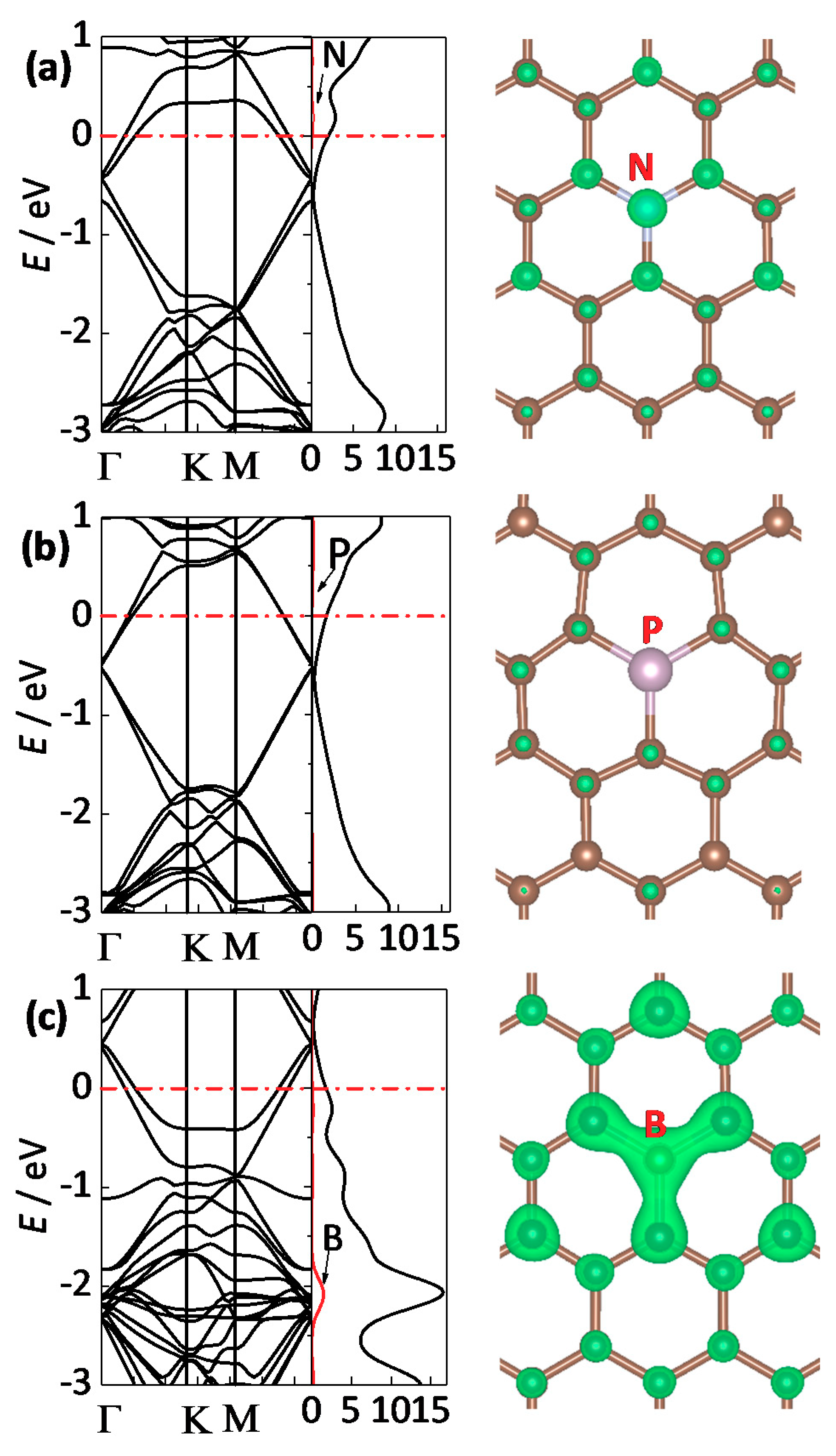
The band structure, DOS and BDCD of doped graphene are shown in Figure 5. For N- and P-doped graphene, the Fermi level shift up into the conduction band due to the electron donation by the N and P atom, as shown in Figure 5a,b. Hence the QC of these two graphenes are much higher in the low voltage range (below 0.3 V) because their DOS are higher when energy is below 0.3 eV. However, their DOS decrease when the energy decrease. Therefore, the QC become smaller than that of the pristine graphene (above 0.3 V). Although their DOS increase after the minimum, the QC of the N- and P-doped graphene is still lower than that of the pristine graphene in the voltage range between 0 and 1.0 V. The results are different for B-doped graphene. As B is an electron acceptor, the Fermi level of B-doped graphene shift downward into the valence band of graphene. Thus, a higher DOS can be found in the energy range between the Fermi level and −1.0 eV. Hence the QC and ESCD of B-doped graphene are much higher than that of pristine graphene. Therefore, for an LIC cathode in which the electron is extracted when it is charged, an electron-accepting dopant is highly favored.
From the BDCD shown in Figure 5, it can be seen that the band with a high pz character contributes to the QC of these three kinds of doped graphene, which follow the case of defected graphene. For the N- and B-doped graphene, this is the state caused by the alien atom and the carbon atoms connecting to the alien atom and their equivalent in the same sublattice. However, the P atom seldom has an effect on the voltage range of LIC. The split DOS of the N, P and B atom in doped graphene shown in Figure S3 also supports this result.
2.3. Unbonded Atoms
As mentioned above, an unbonded atom is present in D1 defected graphene and graphene with pyrrolic and pyridinic N. Therefore, the σ band associated with the unbonded atoms should also affect QC.
The QC and ESCD of the three kinds of graphene are shown in Figure 6. Compared to the pristine graphene, they all deliver much higher QC. Graphene with pyrrolic and pyridinic N even peakes at 108.6 μF/cm2 (0.45 V) and 84.8 μF/cm2 (1.0 V), respectively. As shown in Figure 6b, when the voltage reaches 1.0 V, the ESCD of the D1 defected graphene and graphene with pyridinic and pyrrolic N are 44.6, 53.8, 75.5 μC/cm2, respectively, higher than that of the pristine graphene (9.0 μC/cm2). Therefore, the presence of unbonded atoms can contribute markedly to the energy storage ability. Considering that Celectrolyte is typically around 20 μF/cm2 [15], Cgraphene no longer limits Ctot, and it is the Celectrolyte that dominates Ctot.
The electronic structure and BDCD of graphene with unbonded atoms are shown in Figure 7. It is found that the DOS of D1 defected graphene is very high near the Fermi level. These states mostly stem from the unbonded carbon atom, as shown in Figure S4. In the pyrrolic N configuration, the electronic states of the pyrrolic N atom are mainly below −2.5 eV, as shown in Figure S4. Therefore, it cannot be effectively used in the voltage range of a LIC cathode (0–1.0 V) while the states derived from the σ orbital of unbonded carbon atom are available for energy storage. Since there are two unbonded carbon atoms in graphene with pyrrolic N, the available states are more abundant near the Fermi level. Finally, the QC of graphene with pyrrolic N is much higher than that of D1 defected graphene. In pyridinic N-doped graphene, the distinct DOS peak between −1.0 eV and the Fermi level is due primarily to the σ band localized on the N atom, as shown by the corresponding split DOS in Figure 7 and Figure S4. However, the band associated with the σ orbital from the two unbonded carbon atoms is hard to be detected in this energy range. A C–C bond tends to form due to the fact that the distance of the two unbonded carbon atoms is the smallest compared to D1 defected graphene and graphene with pyrrolic N.
2.4. Residual Oxygen
Oxygen is usually found in GO fabricated by the modified Hummer’s method. After heat treatment or chemical reduction, most of the O will be removed, but there are still many residual O-containing functional groups, such as bridged oxygen (–COC–) and hydroxyl (–OH) and carbonyl (C=O) [42]. We focus on the groups located on the basal plane of rGO in this work. Therefore, C=O, which is mostly found at the edge of rGO, was not considered and only bridged oxygen (–COC–) and hydroxyl (–OH) are investigated. The QC and ESCD of rGO with –COC– and –OH are shown in Figure 8. The QC of the two types of rGO are higher than that of pristine graphene in this figure. Therefore, the presence of both types of O have a positive effect on the energy storage ability, although the O in –COC– has a very limited effect. The QC of rGO with –OH fluctuates with increasing voltage and peaks at 29.5 μF/cm2, while the capacitance peak of rGO with –COC– is 21.6 μF/cm2. The ESCD of two kinds of rGO are 11.3 μC/cm2 and 16.6 μC/cm2, respectively. Therefore, the energy storage ability of rGO with residual O atoms is similar to that of graphene with D2_III, which is still lower than D2_II defected graphene and graphene with B and unbonded atoms.
As shown in Figure 8, a band gap can be seen in the electronic structure of rGO with –OH, thus its QC fluctuates with increasing voltage. The O atoms in both kinds of rGO contribute to electronic states below the Fermi level. The BDCD results show that the states of the O atom, as well as the π electron from carbon atoms, are the origin of QC. However, most of the states stemming from the O atom in the –COC– group are located below −1.0 eV. As shown in Figure 9a and Figure S5, the partial DOS (pDOS) of O in the –COC- functional group peaks at −2.45 eV. The BDCD of O in the energy range between −3.0 eV and the Fermi level is much higher than that between the −1.0 eV and Fermi level. Therefore, the O atom in the –COC– group have no obvious positive effect on the QC and ESCD in the potential range of the LIC cathode. Only when the applied voltage is up to 2.45V, the O in the –COC– really contributes. The O in the –OH group also show similar behavior. In Figure 9b and Figure S6, the pDOS and BDCD of O in –OH is higher than that of the O in –COC–. However, its contribution is still not fully utilized until the applied voltage is above 2.15 V.
Other than its own contribution, the presence of the O atom also affect the electron distribution of graphene. Unlike the pristine graphene, in which the states contributing to QC distribute homogeneously on each carbon atom, only the states quasi-localized on carbon atoms that are not in the sublattice of the carbon atom connecting the O contribute to QC. This is due to the fact that since the O atom form a covalent bond with the carbon atoms in the graphene lattice, the pz orbital of the carbon atoms connected to O atoms participate in this bond. However, considering that the limited effect on QC and the presence of oxygen atoms will decrease the electronic conductivity and even cause irreversible side reactions, O should be further removed before the graphene being used in LIC. Pseudocapacitance can be found in a supercapacitor with aqueous electrolyte when oxygen-containing carbon materials are used as the electrode due to their electrochemical reaction with H+. However, an aprotic solvent, such as ethylene carbonate (EC), propylene carbonate (PC), dimethyl carbonate (DMC), is used in LIC electrolyte due to its high working voltage. Thus, pseudocapacitance will very seldom be found for O atoms in LIC.
3. Theoretical Calculation Methods
Many studies have used the DFT method to compute the QC of graphene. Most of these are based on fixed-band approximation, in which the band structure and the DOS of graphene are assumed to be not affected by the electron extracting process [19,30,31,32,33,34,35,43]. Although the result will be more accurate if the band structure variation is taken into account [44,45], the fixed-band approximation is still adopted here because it provides a quick response for comparison.
Q is the surface charge on the graphene, and ϕ is the applied voltage in the graphene cathode. Hence,
f(E) is the Fermi–Dirac distribution function of the electrons, and E is the relative energy with respect to the Fermi level. e is the elementary charge. According to the definition of capacitance, the derivative dQ/dφ equals the QC (CQ),
is the excessive surface charge density when ϕ changes. The graphene electrochemical potential is shifted by eϕ when the applied bias voltage is ϕ.
The variation range of ϕ is 0–1.0 V in this calculation.
DFT calculation was performed within the Perdew–Burke–Ernzerhof generalized gradient approximation (GGA-PBE), using the Vienna Ab Initio Simulation Package (VASP 5.4) [46]. The projector augmented wave (PAW) method was employed to describe the interaction between core and valence electrons [47]. The kinetic energy cutoff plane wave basis was set to be a 550 eV. 6 × 6 lateral supercell with a lattice constant of 14.796 Å, used for different kinds of graphene. A vacuum slab with a thickness of 20 Å was set above the graphene sheet. The conjugate gradient relaxation algorithm with a fixed lattice constant was used for ionic position optimization, and this relaxation process will stop when all forces are smaller than 0.01. A 5 × 5 × 1, 9 × 9 × 1, and 12 ×12 × 1 k-point mesh was used to sample the Brillouin zone for optimization, energy and DOS calculation.
4. Conclusions
We find that point defects and alien atoms promote the QC behavior and hence the energy storage ability of graphene cathodes in LIC. However, the results strongly depend on the detailed structures and the electron origin was different. D2_II, D2_III and B-doped graphene possess much higher QC than pristine graphene, while SW, D2_I, graphitic N and P have no obvious effect on the voltage range of 0–1.0 V. D1 defected graphene and graphene with pyrrolic, pyridine N show very high QC and their energy storage ability is greatly improved due to the presence of unbonded atoms. Therefore, these types of graphene are good candidates for LIC cathodes. The presence of O can also promote the energy storage ability of graphene cathodes in LIC. However, the enhancement is very limited.
When it comes to the real word, it is very difficult to fabricate graphene with the exact structure investigated in this paper. Many kinds of defects and dopants are present in graphene simultaneously and only certain structures dominate. For graphitic N, P and B, post-high temperature heat treatment can be used to improve their content in the graphene lattice. Graphene with pyridinic N or pyrrolic N can be obtained by carefully choosing the precursor of C and N in the CVD [48] or thermal annealing process [49]. For the point defects, the hardest work is almost tailoring their type and position in the graphene lattice. Considering that the formation energy is different, post-heat treatment may also be employed to control the point defects.
The QC origin of the graphene cathode can provide insight for further studies of its catalytic effect on electrolyte oxidation when the LIC is charged. Graphene with defects and graphitic N, and P and B dopant will be stable with electrolyte due to the relatively stable π states contributing to the QC. However, when unbonded atoms are present in the graphene, the electrolyte may be easily decomposed due to the high reactive σ states. Therefore, the D1 defected graphene and graphene with pyrrolic, pyridine N should be utilized with great care although they show excellent energy storage ability. Further profound work on this catalytic electrochemical reaction mechanism is ongoing.
Supplementary Materials
The following are available online at https://www.mdpi.com/2073-4344/8/10/444/s1, Figure S1: Band structure, DOS and band-decomposed charge density iso-surces (0.003 e/Bohr3) of D2_II defected graphene; Figure S2: Band structure, DOS and band-decomposed charge density iso-surces (0.003 e/Bohr3) of D2_III defected graphene; Figure S3: Split DOS of alien atoms in B, N and P doped graphene; Figure S4: Split DOS and spin density of D1 defected graphene and graphene with pyrrolic and pyridinic N; Figure S5: Split DOS of O in –COC– group and the band-decomposed charge density iso-surces (0.01 e/Bohr3) at different energy range; Figure S6: Split DOS of O in –OH group and the band-decomposed charge density iso-surces (0.01 e/Bohr3) at different energy range.
Author Contributions
Investigation and writing original draft, F.S.; formal analysis and review and editing, L.H.; validation, Q.K.; data curation, L.X., project administration, C.C.
Funding
This research was funded by the National Natural Science Foundation of China (grant number 51402325), the Scientific and Technological Key Project of Shanxi Province (grant number MC2016-04 and 20141101003).
Acknowledgments
The authors acknowledge the Supercomputer Center in Lvliang, China, for providing computational resources.
Conflicts of Interest
The authors declare no competing financial interest.
References
- Amatucci, G.G.; Badway, F.; Du Pasquier, A.; Zheng, T. An asymmetric hybrid nonaqueous energy storage cell. J. Electrochem. Soc. 2001, 148, A930–A939. [Google Scholar] [CrossRef]
- Khomenko, V.; Raymundo-Piñero, E.; Béguin, F. High-energy density graphite/ac capacitor in organic electrolyte. J. Power Sources 2008, 177, 643–651. [Google Scholar] [CrossRef]
- Decaux, C.; Lota, G.; Raymundo-Pinero, E.; Frackowiak, E.; Beguin, F. Electrochemical performance of a hybrid lithium-ion capacitor with a graphite anode preloaded from lithium bis(trifluoromethane)sulfonimide-based electrolyte. Electrochim. Acta 2012, 86, 282–286. [Google Scholar] [CrossRef]
- Cao, W.J.; Zheng, J.P. The effect of cathode and anode potentials on the cycling performance of li-ion capacitors. J. Electroche. Soc. 2013, 160, A1572–A1576. [Google Scholar] [CrossRef]
- Yu, X.; Zhan, C.; Lv, R.; Bai, Y.; Lin, Y.; Huang, Z.-H.; Shen, W.; Qiu, X.; Kang, F. Ultrahigh-rate and high-density lithium-ion capacitors through hybriding nitrogen-enriched hierarchical porous carbon cathode with prelithiated microcrystalline graphite anode. Nano Energy 2015, 15, 43–53. [Google Scholar] [CrossRef]
- Aida, T.; Murayama, I.; Yamada, K.; Morita, M. Improvement in cycle performance of a high-voltage hybrid electrochemical capacitor. Electrochem. Solid-State Lett. 2007, 10, A93–A96. [Google Scholar] [CrossRef]
- Cao, W.J.; Zheng, J.P. Li-ion capacitors with carbon cathode and hard carbon/stabilized lithium metal powder anode electrodes. J. Power Sources 2012, 213, 180–185. [Google Scholar] [CrossRef]
- Cheng, L.; Liu, H.-J.; Zhang, J.-J.; Xiong, H.-M.; Xia, Y.-Y. Nanosized Li4Ti5O12 prepared by molten salt method as an electrode material for hybrid electrochemical supercapacitors. J. Electrochem. Soc. 2006, 153, A1472–A1477. [Google Scholar] [CrossRef]
- Lee, J.H.; Shin, W.H.; Ryou, M.-H.; Jin, J.K.; Kim, J.; Choi, J.W. Functionalized graphene for high performance lithium ion capacitors. ChemSusChem 2012, 5, 2328–2333. [Google Scholar] [CrossRef] [PubMed]
- Stoller, M.D.; Murali, S.; Quarles, N.; Zhu, Y.; Potts, J.R.; Zhu, X.; Ha, H.-W.; Ruoff, R.S. Activated graphene as a cathode material for li-ion hybrid supercapacitors. Phys.Chem. Chem. Phys. 2012, 14, 3388–3391. [Google Scholar] [CrossRef] [PubMed]
- Leng, K.; Zhang, F.; Zhang, L.; Zhang, T.; Wu, Y.; Lu, Y.; Huang, Y.; Chen, Y. Graphene-based li-ion hybrid supercapacitors with ultrahigh performance. Nano. Res. 2013, 6, 581–592. [Google Scholar] [CrossRef]
- Aravindan, V.; Mhamane, D.; Ling, W.C.; Ogale, S.; Madhavi, S. Nonaqueous lithium-ion capacitors with high energy densities using trigol-reduced graphene oxide nanosheets as cathode-active material. ChemSusChem 2013, 6, 2240–2244. [Google Scholar] [CrossRef] [PubMed]
- Wang, H.; Guan, C.; Wang, X.; Fan, H.J. A high energy and power li-ion capacitor based on a tio2 nanobelt array anode and a graphene hydrogel cathode. Small 2015, 11, 1470–1477. [Google Scholar] [CrossRef] [PubMed]
- John, D.L.; Castro, L.C.; Pulfrey, D.L. Quantum capacitance in nanoscale device modeling. J.Appl.Phys. 2004, 96, 5180–5184. [Google Scholar] [CrossRef] [Green Version]
- Xia, J.; Chen, F.; Li, J.; Tao, N. Measurement of the quantum capacitance of graphene. Nat. Nano. 2009, 4, 505–509. [Google Scholar] [CrossRef] [PubMed]
- Stoller, M.D.; Magnuson, C.W.; Zhu, Y.W.; Murali, S.; Suk, J.W.; Piner, R.; Ruoff, R.S. Interfacial capacitance of single layer graphene. Energy Environ. Sci. 2011, 4, 4685–4689. [Google Scholar] [CrossRef]
- Ji, H.; Zhao, X.; Qiao, Z.; Jung, J.; Zhu, Y.; Lu, Y.; Zhang, L.L.; MacDonald, A.H.; Ruoff, R.S. Capacitance of carbon-based electrical double-layer capacitors. Nat. Commun. 2014, 5, 3317. [Google Scholar] [CrossRef] [PubMed] [Green Version]
- Ebrish, M.A.; Olson, E.J.; Koester, S.J. Effect of noncovalent basal plane functionalization on the quantum capacitance in graphene. ACS Appl. Mater. Interfaces 2014, 6, 10296–10303. [Google Scholar] [CrossRef] [PubMed]
- Paek, E.; Pak, A.J.; Hwang, G.S. A computational study of the interfacial structure and capacitance of graphene in [bmim][pf6] ionic liquid. J. Electrochem. Soc. 2013, 160, A1–A10. [Google Scholar] [CrossRef]
- Lee, J.H.; Shin, W.H.; Lim, S.Y.; Kim, B.G.; Choi, J.W. Modified graphite and graphene electrodes for high-performance lithium ion hybrid capacitors. Mater. Renew. Sustain. Energy 2014, 3, 1–8. [Google Scholar] [CrossRef]
- Tu, F.Y.; Liu, S.Q.; Wu, T.H.; Jin, G.H.; Pan, C.Y. Porous graphene as cathode material for lithium ion capacitor with high electrochemical performance. Powder Technol. 2014, 253, 580–583. [Google Scholar] [CrossRef]
- Yu, X.; Deng, J.; Zhan, C.; Lv, R.; Huang, Z.-H.; Kang, F. A high-power lithium-ion hybrid electrochemical capacitor based on citrate-derived electrodes. Electrochim. Acta 2017, 228, 76–81. [Google Scholar] [CrossRef]
- Banhart, F.; Kotakoski, J.; Krasheninnikov, A.V. Structural defects in graphene. ACS Nano 2011, 5, 26–41. [Google Scholar] [CrossRef] [PubMed]
- Palacios, J.J.; Ynduráin, F. Critical analysis of vacancy-induced magnetism in monolayer and bilayer graphene. Phys. Rev. B 2012, 85, 245443. [Google Scholar] [CrossRef]
- Hou, Z.F.; Wang, X.L.; Ikeda, T.; Terakura, K.; Oshima, M.; Kakimoto, M.; Miyata, S. Interplay between nitrogen dopants and native point defects in graphene. Phys. Rev. B 2012, 85, 165439. [Google Scholar] [CrossRef] [Green Version]
- Latorre-Sánchez, M.; Primo, A.; García, H. P-Doped Graphene Obtained by Pyrolysis of Modified Alginate as a Photocatalyst for Hydrogen Generation from Water–Methanol Mixtures. Angew. Chem.-Int. Ed. 2013, 52, 11813–11816. [Google Scholar] [CrossRef] [PubMed]
- Liu, M.; Zhang, R.; Chen, W. Graphene-supported nanoelectrocatalysts for fuel cells: synthesis, properties, and applications. Chem. Rev. 2014, 114, 5117–5160. [Google Scholar] [CrossRef] [PubMed]
- Wood, K.N.; O’Hayre, R.; Pylypenko, S. Recent progress on nitrogen/carbon structures designed for use in energy and sustainability applications. Energy Environ. Sci. 2014, 7, 1212–1249. [Google Scholar] [CrossRef]
- Wood, B.C.; Ogitsu, T.; Otani, M.; Biener, J. First-principles-inspired design strategies for graphene-based supercapacitor electrodes. J. Phys. Chem. C 2014, 118, 4–15. [Google Scholar] [CrossRef]
- Vatamanu, J.; Ni, X.; Liu, F.; Bedrov, D. Tailoring graphene-based electrodes from semiconducting to metallic to increase the energy density in supercapacitors. Nanotechnology 2015, 26, 464001. [Google Scholar] [CrossRef] [PubMed] [Green Version]
- Zhan, C.; Zhang, Y.; Cummings, P.T.; Jiang, D.-E. Computational insight into the capacitive performance of graphene edge planes. Carbon 2017, 116, 278–285. [Google Scholar] [CrossRef]
- Pak, A.J.; Paek, E.; Hwang, G.S. Tailoring the performance of graphene-based supercapacitors using topological defects: A theoretical assessment. Carbon 2014, 68, 734–741. [Google Scholar] [CrossRef]
- Zhan, C.; Zhang, Y.; Cummings, P.T.; Jiang, D.E. Enhancing graphene capacitance by nitrogen: Effects of doping configuration and concentration. Phys. Chem. Chem. Phys. 2016, 18, 4668–4674. [Google Scholar] [CrossRef] [PubMed]
- Yang, G.M.; Zhang, H.Z.; Fan, X.F.; Zheng, W.T. Density functional theory calculations for the quantum capacitance performance of graphene-based electrode material. J. Phys. Chem. C 2015, 119, 6464–6470. [Google Scholar] [CrossRef]
- Paek, E.; Pak, A.J.; Kweon, K.E.; Hwang, G.S. Non the origin of the enhanced supercapacitor performance of nitrogen-doped graphene. J. Phys. Chem. C 2013, 117, 5610–5616. [Google Scholar] [CrossRef]
- Mousavi-Khoshdel, S.M.; Targholi, E.; Momeni, M.J. A first principle calculation of quantum capacitance of co-doped graphenes as supercapacitor electrodes. J. Phys. Chem. C 2015, 119, 26290–26295. [Google Scholar] [CrossRef]
- Paek, E.; Pak, A.J.; Hwang, G.S. Large capacitance enhancement induced by metal-doping in graphene-based supercapacitors: A first-principles-based assessment. ACS Appl. Mater. Interfaces 2014, 6, 12168–12176. [Google Scholar] [CrossRef] [PubMed]
- Naoi, K. Nanohybrid capacitor: The next generation electrochemical capacitors. Fuel Cells 2010, 10, 825–833. [Google Scholar] [CrossRef]
- Dubal, D.P.; Ayyad, O.; Ruiz, V.; Gomez-Romero, P. Hybrid energy storage: The merging of battery and supercapacitor chemistries. Chem. Soc. Rev. 2015, 44, 1777–1790. [Google Scholar] [CrossRef] [PubMed]
- Zheng, J.; Xiao, J.; Xu, W. Surface and structural stabilities of carbon additives in high voltage lithium ion batteries. J. Power Sources 2013, 227, 211–217. [Google Scholar] [CrossRef]
- Kurzweil, P.; Chwistek, M. Electrochemical stability of organic electrolytes in supercapacitors: Spectroscopy and gas analysis of decomposition products. J. Power Sources 2008, 176, 555–567. [Google Scholar] [CrossRef]
- Pei, S.; Cheng, H.-M. The reduction of graphene oxide. Carbon 2012, 50, 3210–3228. [Google Scholar] [CrossRef]
- Zhan, C.; Neal, J.; Wu, J.; Jiang, D. Quantum effects on the capacitance of graphene-based electrodes. J. Phys. Chem. C 2015, 119, 22297–22303. [Google Scholar] [CrossRef]
- Radin, M.D.; Ogitsu, T.; Biener, J.; Otani, M.; Wood, B.C. Capacitive charge storage at an electrified interface investigated via direct first-principles simulations. Phys. Rev. B 2015, 91, 125415. [Google Scholar] [CrossRef]
- Cheng, Z.; De-en, J. Understanding the pseudocapacitance of RuO2 from joint density functional theory. J. Phys.-Condens. Mat. 2016, 28, 464004. [Google Scholar]
- Kresse, G.; Furthmüller, J. Efficient iterative schemes for ab initio total-energy calculations using a plane-wave basis set. Phys. Rev. B 1996, 54, 11169–11186. [Google Scholar] [CrossRef]
- Blöchl, P.E. Projector augmented-wave method. Phys. Rev. B 1994, 50, 17953–17979. [Google Scholar] [CrossRef] [Green Version]
- Luo, Z.; Lim, S.; Tian, Z. Pyridinic N doped graphene: synthesis, electronic structure, and electrocatalytic property. J. Mater. Chem. 2011, 21, 8038–8044. [Google Scholar] [CrossRef]
- Lai, L.; Potts, J.R.; Zhan, D.; Wang, L.; Poh, C.K.; Tang, C.; Gong, H.; Shen, Z.; Lin, J.; Ruoff, R.S. Exploration of the active center structure of nitrogen-doped graphene-based catalysts for oxygen reduction reaction. Energy Environ. Sci. 2012, 5, 7936–7942. [Google Scholar] [CrossRef]
Figure 1.
Geometric structure of pristine and defected graphene. (a) Pristine, (b) SW (55-77), (c) D1 (5-9), (d) D2_I (5-8-5), (e) D2_II (555-777) and (f) D2_III (5555-6-7777).
Figure 1.
Geometric structure of pristine and defected graphene. (a) Pristine, (b) SW (55-77), (c) D1 (5-9), (d) D2_I (5-8-5), (e) D2_II (555-777) and (f) D2_III (5555-6-7777).

Figure 2.
Energy storage performance of pristine and graphene with Stone–Wales (SW) and D2 defects. (a) quantum capacitance (QC) and (b) excessive surface charge density (ESCD).
Figure 2.
Energy storage performance of pristine and graphene with Stone–Wales (SW) and D2 defects. (a) quantum capacitance (QC) and (b) excessive surface charge density (ESCD).

Figure 3.
Band structure, density of states (DOS) and band-decomposed charge density (BDCD) iso-sources (0.006 e/Bohr3) of (a) pristine; (b) SW; (c) D2_I; (d) D2_II and (e) D2_III defected graphene.
Figure 3.
Band structure, density of states (DOS) and band-decomposed charge density (BDCD) iso-sources (0.006 e/Bohr3) of (a) pristine; (b) SW; (c) D2_I; (d) D2_II and (e) D2_III defected graphene.

Figure 4.
Energy storage performance of doped graphene. (a) quantum capacitance (QC) and (b) excessive surface charge density (ESCD).
Figure 4.
Energy storage performance of doped graphene. (a) quantum capacitance (QC) and (b) excessive surface charge density (ESCD).

Figure 5.
Band structure, density of states (DOS) and band-decomposed charge density (BDCD) iso-surface of (a) N-doped graphene (0.003 e/Bohr3); (b) P-doped graphene (0.003 e/Bohr3) and (c) B-doped graphene (0.006 e/Bohr3).
Figure 5.
Band structure, density of states (DOS) and band-decomposed charge density (BDCD) iso-surface of (a) N-doped graphene (0.003 e/Bohr3); (b) P-doped graphene (0.003 e/Bohr3) and (c) B-doped graphene (0.006 e/Bohr3).

Figure 6.
Energy storage performance of pristine, D1 defected graphene and graphene with pyrrolic N and pyridinic N. (a) quantum capacitance (QC) and (b) excessive surface charge density (ESCD).
Figure 6.
Energy storage performance of pristine, D1 defected graphene and graphene with pyrrolic N and pyridinic N. (a) quantum capacitance (QC) and (b) excessive surface charge density (ESCD).

Figure 7.
Band structure, density of states (DOS) and band-decomposed charge density (BDCD) iso-surces (0.006 e/Bohr3) of (a) D1 defected graphene; (b) pyrrolic and (c) pyridine N doping graphene.
Figure 7.
Band structure, density of states (DOS) and band-decomposed charge density (BDCD) iso-surces (0.006 e/Bohr3) of (a) D1 defected graphene; (b) pyrrolic and (c) pyridine N doping graphene.

Figure 8.
Energy storage performance of graphene with different residue oxygen. (a) quantum capacitance (QC) and (b) excessive surface charge density (ESCD).
Figure 8.
Energy storage performance of graphene with different residue oxygen. (a) quantum capacitance (QC) and (b) excessive surface charge density (ESCD).

Figure 9.
Band structure, density of states (DOS) and band-decomposed charge density (BDCD) iso-surfaces (0.006e/Bohr3) of (a) graphene with –COC–; (b) graphene with –OH.
Figure 9.
Band structure, density of states (DOS) and band-decomposed charge density (BDCD) iso-surfaces (0.006e/Bohr3) of (a) graphene with –COC–; (b) graphene with –OH.

© 2018 by the authors. Licensee MDPI, Basel, Switzerland. This article is an open access article distributed under the terms and conditions of the Creative Commons Attribution (CC BY) license (http://creativecommons.org/licenses/by/4.0/).
Share and Cite
MDPI and ACS Style
Su, F.; Huo, L.; Kong, Q.; Xie, L.; Chen, C. Theoretical Study on the Quantum Capacitance Origin of Graphene Cathodes in Lithium Ion Capacitors. Catalysts 2018, 8, 444. https://doi.org/10.3390/catal8100444
AMA Style
Su F, Huo L, Kong Q, Xie L, Chen C. Theoretical Study on the Quantum Capacitance Origin of Graphene Cathodes in Lithium Ion Capacitors. Catalysts. 2018; 8(10):444. https://doi.org/10.3390/catal8100444
Chicago/Turabian StyleSu, Fangyuan, Li Huo, Qingqiang Kong, Lijing Xie, and Chengmeng Chen. 2018. "Theoretical Study on the Quantum Capacitance Origin of Graphene Cathodes in Lithium Ion Capacitors" Catalysts 8, no. 10: 444. https://doi.org/10.3390/catal8100444
Note that from the first issue of 2016, this journal uses article numbers instead of page numbers. See further details here.