Article

Morphologically Tunable MnO2 Nanoparticles Fabrication, Modelling and Their Influences on Electrochemical Sensing Performance toward Dopamine

1
School of Material Science and Energy Engineering, Foshan University, Foshan 528000, China
2
College of Life Sciences and Chemistry, Hunan University of Technology, Zhuzhou 412007, China
3
Department of Chemistry and Material Science, Hengyang Normal University, Hengyang 421008, China
*
Authors to whom correspondence should be addressed.
These authors contributed equally to this work.
Catalysts 2018, 8(8), 323; https://doi.org/10.3390/catal8080323
Submission received: 4 July 2018 / Revised: 3 August 2018 / Accepted: 6 August 2018 / Published: 8 August 2018
(This article belongs to the Section Electrocatalysis)

Abstract

:
The morphology or shape of nanomaterials plays an important role in functional applications, especially in the electrochemical sensing performance of nanocomposites modified electrodes. Herein, the morphology-dependent electrochemical sensing properties of MnO2-reduced graphene oxide/glass carbon electrode (MnO2-RGO/GCE) toward dopamine detection were investigated. Firstly, various morphologies of nanoscale MnO2, including MnO2 nanowires (MnO2 NWs), MnO2 nanorods (MnO2 NRs), and MnO2 nanotubes (MnO2 NTs), were synthesized under different hydrothermal conditions. Then the corresponding MnO2-RGO/GCEs were fabricated via drop-casting and the subsequent electrochemical reduction method. The oxidation peak currents increase with the electrochemical activity area following the order of MnO2 NWs-RGO/GCE, MnO2 NTs-RGO/GCE, and MnO2 NRs-RGO/GCE. The spatial models for MnO2 NWs, MnO2 NTs, and MnO2 NRs are established and accordingly compared by their specific surface area, explaining well the evident difference in electrochemical responses. Therefore, the MnO2 NWs-RGO/GCE is selected for dopamine detection due to its better electrochemical sensing performance. The response peak current is found to be linear with dopamine concentration in the range of 8.0 × 10⁻⁸ mol/L–1.0 × 10−6 mol/L and 1.0 × 10⁻⁶ mol/L–8.0 × 10−5 mol/L with a lower detection limit of 1 × 10⁻⁹ mol/L (S/N = 3). Finally, MnO2 NWs-RGO/GCE is successfully used for the determination of dopamine injection samples, with a recovery of 99.6–103%. These findings are of great significance for understanding the relationship between unlimited nanoparticle structure manipulation and performance improvement.

1. Introduction

Dopamine is an important neurotransmitter that plays a vital role in the regulation of cognitive and neuroendocrine functions, as well as emotions and sleep [1]. An abnormal level of dopamine may cause several central nervous system diseases such as depression, anxiety, schizophrenia, and Parkinson’s disease [2,3,4,5]. Therefore, it is of great significance to detect dopamine accurately at a physiological level in the earlier prevention and clinical diagnosis of these neurological diseases. To date, various techniques have been developed to detect dopamine, including but not limited to high performance liquid chromatography [6], mass spectrometry, fluorescent spectrometry [7], capillary electrophoresis [8,9], and electrochemiluminescence [10,11]. Despite being reliable and precise, these methods often suffer from drawbacks such as expensive instruments, complex and time-consuming analytical procedures, and the requirement of experienced technical staff. Recently, electrochemical methods have been widely applied to detect biomolecules, contaminants, and food additives, due to overwhelming advantages including cost- and time- effectiveness, rapidness and simplicity, as well as good selectivity and sensitivity. The key issue to electroanalytical chemistry lies in the development of ultrasensitive modified electrodes. Precious metal nanoparticles and nanoalloys modified electrodes have exhibited superior sensing performances (i.e., wide linear ranges, low detection limit, good stability and selectivity) [12,13,14], but their scarcity and cost has limited practical applications. To solve this problem, various transition metals or metal oxides modified electrodes have become ideal alternative modification materials [15,16,17,18].
MnO2, an important transition metal oxide, has been extensively used in rechargeable batteries [19], supercapacitors [20,21], electrocatalysis [22,23], and sensors [24,25,26,27,28], owing to its prominent advantages such as cheapness, low toxicity, and excellent electrocatalytic performances. Moreover, the electrochemical performance can be tailored by tuning the morphologies of nano-MnO2 [25]. However, the poor electrical conductivity has hindered its broad applications in electrochemical sensors, due to the semiconductor property of itself [26]. Hence, much effort has been devoted to composite or hybrid nano-MnO2 with conductive components, aiming to enhance electrical conductivity, decrease charge transfer resistance, and eventually improve sensing performances [20,21,29]. Graphene, an emerging 2D carbon nanomaterial, has become one of the most preferred electrode modification materials due to its large surface area, high electrical conductivity, and rapid heterogeneous electron transfer rate [27,30,31]. In recent years, MnO2-graphene nanocomposite modified electrodes have been widespread in electrochemical sensors. For example, Wu and co-workers developed a non-enzymatically catalyzed H2O2 sensor based on a MnO2/reduced graphene oxide nanoribbons composite modified electrode, which exhibits excellent electrochemical performance and high precision, as well as good selectivity, reproducibility, and stability [26]. Mahmoudian et al. constructed a H2O2 sensor based on MnO2 nanotubes/reduced graphene oxide nanocomposite modified glassy carbon electrode, and the charge transfer resistance reduced significantly [24]. α-MnO2 nanorods/reduced graphene oxide modified glassy carbon electrodes have been used to detect uric acid with satisfactory results, even in the presence of large amounts of ascorbic acid [32]. In addition, MnO2 nanowire/chitosan modified gold electrodes [28] and Pt nanodendrites/graphene/MnO2 nanoflower modified electrodes [33] have also been successfully used for the detection of dopamine, but precious metal (i.e., Au, Pt) components are very expensive. To our best knowledge, MnO2-graphene binary composite modified electrodes for dopamine detection is rarely reported.
The morphology or shape of nanomaterials play a vital role in the electrochemical sensing performance of modified electrodes. For example, the surface adsorption is tuned via controlled preparation of various shapes of hematite α-Fe2O3 (shuttle-like, pseudo-shuttle-like, polyhedron-like, and drum-like α-Fe2O3), and shuttle-like Fe2O3 exhibits better electrochemical detection ability than other shapes of Fe2O3 nanoparticles [34]. Various morphologies of manganese dioxide (MnO2) electrocatalysts, including nanoflowers, nanorods, nanotubes, nanoplates, nanowires, and microspheres were prepared via facile hydrothermal synthesis and precipitation methods, and their electrochemical properties were found to be strongly dependent on the morphology [35]. Among these various morphologies, the nanoflowers-like MnO2, coupled with GO, exhibited relatively high sensitivity toward the simultaneous determination of guaiacol and vanillin [35]. However, the effect of different morphologies of nano-MnO2 on the dopamine detection is not yet clear. Thus, it is well worth further investigation.
Herein, three different morphologies of nano-MnO2, including nanowires (MnO2 NWs), MnO2 nanorods (MnO2 NRs), and MnO2 nanotubes (MnO2 NTs), were prepared by hydrothermal method firstly, then composited with graphene oxide (GO) to obtain nano-MnO2 counterparts. The MnO2-reduced graphene oxide modified glass carbon electrode (MnO2-RGO/GCE) was prepared by drop-casting MnO2-GO dispersion on the surface of GCE and subsequently an electrochemical reduction process [36,37,38]. The response peak currents were measured by second-order derivative linear sweep voltammetry in dopamine solution. The corresponding peak current densities were estimated by dividing by their electrochemical active area, which was obtained from the cyclic voltammograms using [Fe(CN)6]3−/4− as redox probe. The response peak currents and peak current densities among three various morphologies of MnO2-RGO/GCE have been compared to find out the main factors on the enhancement of electrochemical response. The response peak current is supposed to be proportional to the surface area of the modified electrode, because of the presence of an adsorption-controlled process during electrochemical oxidation of dopamine [34,37,38,39,40,41]. Based on the hypothesis, spatial models for three various morphologies of nano-MnO2 were established to compare their specific surface area, and find the main factors on the specific surface area. Finally, the MnO2-RGO/GCE with the largest response peak current was chosen to detect dopamine in real samples.

2. Results

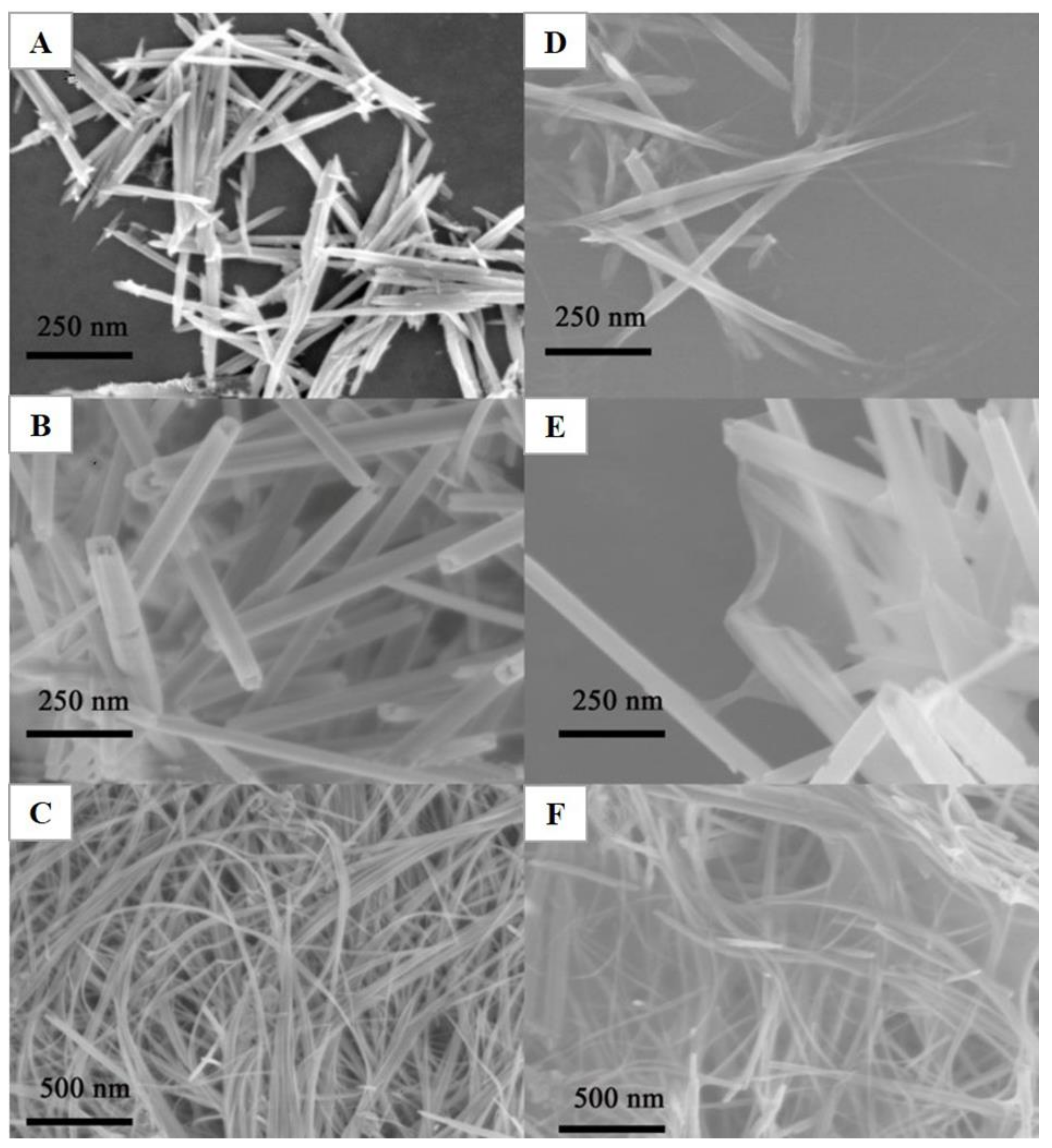
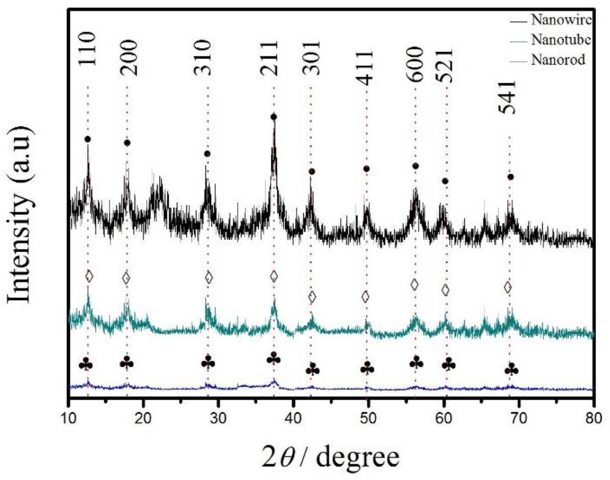
2.1. Materials Characterization

The surface morphologies of MnO2 NRs, MnO2 NTs, MnO2 NWs and their corresponding MnO2-RGO nanocomposites were characterized by scanning electron microscopy (SEM, Hitachi S-3000N, Tokyo, Japan). The SEM images of MnO2 NRs, MnO2 NTs, and MnO2 NWs are shown in Figure 1A–C, respectively. MnO2 NTs show distinct hollow tubular structures with uniform diameters (Figure 1B). MnO2 NWs show obvious line-like structures, and the diameter is uniform (Figure 1C). It can been seen clearly that thin sheets are attached to the surface of MnO2 NRs, MnO2 NTs, and MnO2 NWs (Figure 1D–F) when they were composited with RGO.
The MnO2 NRs, MnO2 NTs, and MnO2 NWs were further characterized by X-ray diffractometer (XRD, PANalytical, Almelo, Holland), operating at 40 kV and 40 mA with Cu Kα radiation (λ = 0.1542 nm). The XRD patterns of MnO2 NRs, MnO2 NTs, and MnO2 NWs are presented in Figure 2. All of the nano-MnO2 appears with obvious diffraction peaks. These diffraction peaks are located at 2θ of 12.78°, 17.68°, 28.28°, 37.48°, 42.36°, 49.94°, 56.34°, 60.16°, and 69.08°, indexing into (110), (200), (310), (211), (301), (411), (600), (521), and (541) facets (JSPDS44-0141), indicating that tetrahedral crystalline α-MnO2 was synthesized.

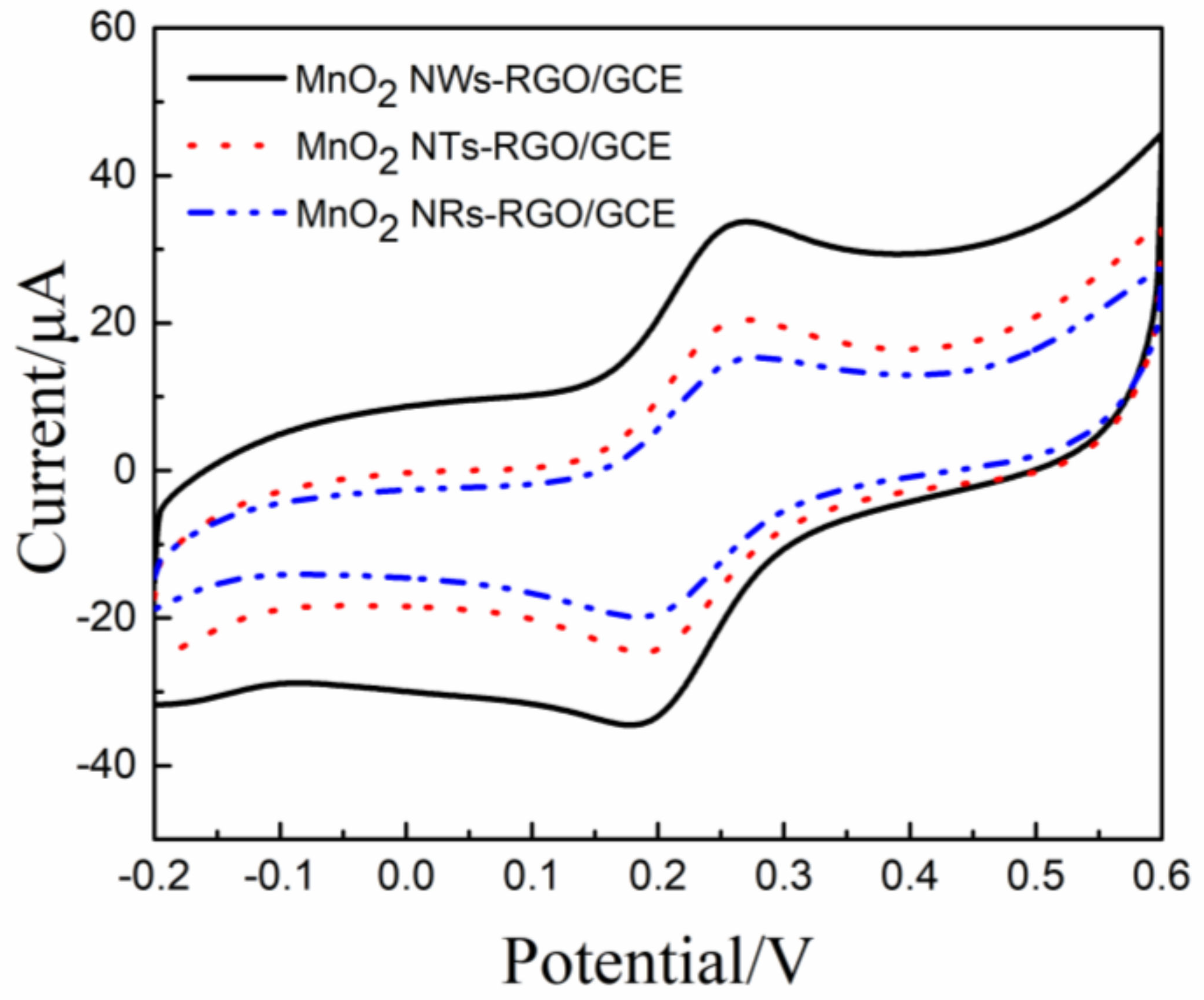
2.2. Voltammetric Responses of Dopamine on the MnO2-RGO/GCEs

The second-order derivative linear sweep voltammetric (SDLSV) response of 1 × 10⁻⁵ mol/L dopamine on the bare GCE, RGO/GCE, MnO2 NRs-RGO/GCE, MnO2 NTs-RGO/GCE, and MnO2 NWs were summarized in Table 1, respectively. The oxidation peak of dopamine on the bare GCE is very weak, and the response current is 1.396 μA. The response peak of dopamine on the RGO/GCE is obvious and the oxidation peak current increases to 22.56 μA, which is an order of magnitude greater than that of the bare GCE. The significant increase in the oxidation peak current is highly related to excellent electrical conductivity and large specific surface area of RGO. The electrical conductivity of RGO is enhanced greatly due to the restoration of the conductive carbon-conjugate networks, which will decrease the electron transfer resistance and accelerate the electron transfer rate. The adsorption capacity also increase due to the large specific surface area of RGO. Besides, the presence of residual oxygen containing functional groups will also promote the dopamine adsorption with the help of π–π interaction. The response peak current of MnO2-RGO/GCE further increases, which is mainly due to the synergistic enhancement effect between nano-MnO2 and RGO. The extra increase mainly arises from the excellent electrocatalytic performance of nano-MnO2. Among three different morphologies of nano-MnO2 composited with RGO, the largest oxidation peak current is obtained at MnO2 NWs-RGO/GCE, the second one on the MnO2-NTs-RGO, and the smallest one on the MnO2 NRs-RGO/GCE. The variation among different morphologies depends on electrochemical active area and electrocatalytic activity per unit area.

2.3. Electrochemical Active Area of MnO2-RGO/GCEs

In order to compare the electrochemical active area of different electrodes, the cyclic voltammograms of the MnO2 NRs-RGO/GCE, MnO2 NTs-RGO/GCE, and MnO2 NWs-RGO/GCE were investigated in the 0.1 mol/L PBS solution containing 1 × 10⁻³ mol/L [Fe(CN)6]3−/4− (Figure 3). Their reduction peak currents (ipc) are 2.158 × 10⁻⁵ A, 1.738 × 10⁻⁵ A, and 1.375 × 10⁻⁵ A, respectively. According to Randles-Sevcik Equation [42]
i pc = ( 2.69 × 10 5 ) n 3 / 2 D 1 / 2 v 1 / 2 A C  
where ipc is the reduction peak current of K3[Fe(CN)6] (A); n is the electron transfer number during the redox process; A is the electrochemical active area (cm2); D is diffusion coefficient of K3[Fe(CN)6] (D = 7.6 × 10⁻⁶ cm2·s−1 [43]); C is the concentration of K3[Fe(CN)6] (mol·cm−3); v is the scanning rate (V·s−1). Therefore, the electrochemical active areas of MnO2 NWs-RGO/GCE, MnO2 NTs-RGO/GCE and MnO2 NRs-RGO/GCE were 0.130 cm2, 0.105 cm2 and 0.0829 cm2, respectively, which are much larger than those of bare GCE (Φ3.0 mm, 0.0710 cm2). It means that the MnO2-RGO composite film increases the specific surface area. The electrochemical active area follows the order of MnO2 NWs-RGO/GCE > MnO2 NTs-RGO/GCE > MnO2 NRs-RGO/GCE. The order of electrochemical active area is consistent with that of their corresponding peak current ipa, confirming that the response peak current (ipa) is closely related to the electrochemical active area. The large electrochemical active area not only facilitates the accumulation of dopamine on the electrode surface, but also increases the catalytic sites on the surface of the modified electrodes.
In order to explore the effect of electrocatalytic activity on the response peak current, the peak current densities are estimated by dividing by their electrochemical area, aiming to exclude the influence of the electrochemical active area. The peak current densities (Ja) of MnO2 NWs-RGO/GCE, MnO2 NRs-RGO/GCE, and MnO2 NTs-RGO/GCE are listed in the fourth column in Table 1. Interestingly, the order of peak current densities is the reverse of that of the electrochemical active area, namely MnO2 NRs-RGO/GCE > MnO2 NTs-RGO/GCE > MnO2 NWs-RGO/GCE. It implies that the response peak current is also highly related to the electrocatalytic activity. The peak current density on the MnO2 NWs-RGO/GCE is smallest while the peak current is largest, suggesting the electrochemical active area plays a major role in enhancing the electrochemical response towards dopamine.
Why does there exist such an evident disparity between different morphological MnO2 nanomaterials? What is the driving force to differentiate electrochemical performances between these three types of morphology? We are trying to simulate their spatial models to deeply reveal the secrets behind them.

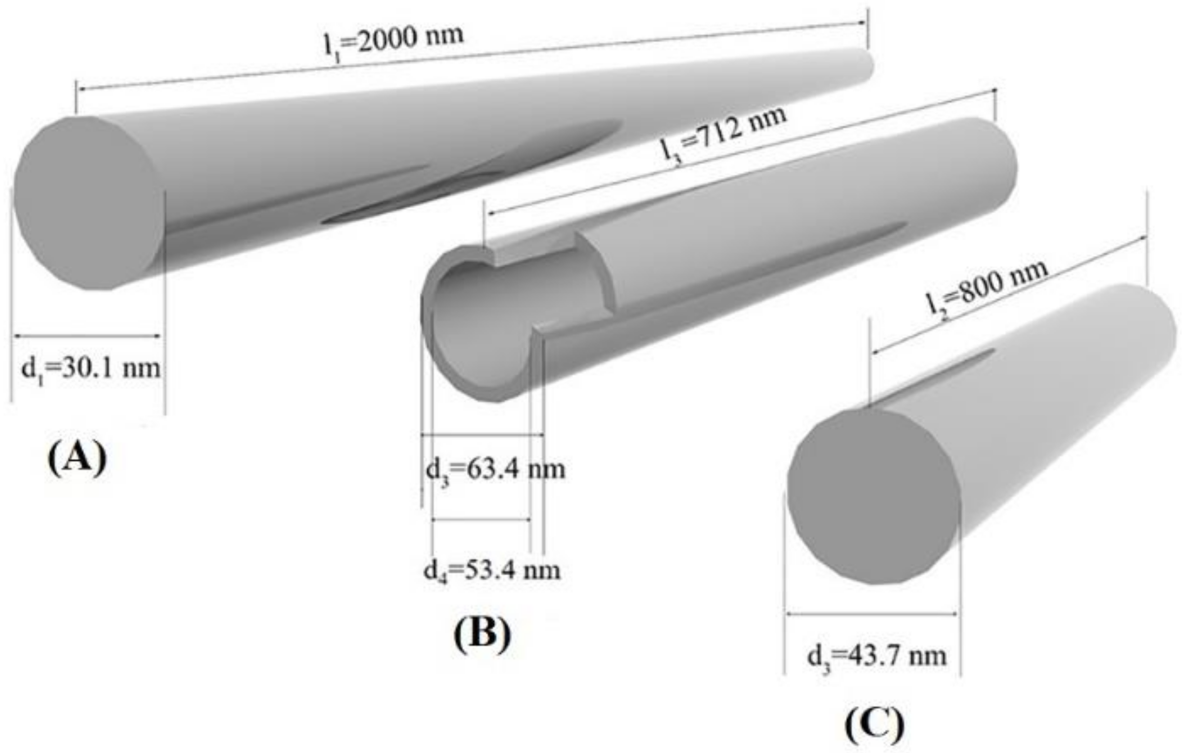
2.4. Spatial Models for Various Morphologies of Nano-MnO2

It has been reported that MnO2 is the reaction active site for the oxidation of electrochemically active species [44]. As is well known, electrocatalytic oxidation of dopamine on the surface of modified electrodes is mainly controlled by the adsorption process [34,37,38,39,40,41]. Hence, the response peak current can be calculated according to the Laviron Equation [45]:
i p = n 2 F 2 Γ 4 R T A v  
where Г denotes surface coverage, n denotes the electron transfer number, A denotes the surface area of the electrode, v denotes the scan rate, and T denotes the Kelvin temperature. The surface coverage (Г) can be considered as a constant due to the same bulk dopamine concentration for three morphologies of MnO2.
Nanorods and nanowires are generally distinguished by their length-to-diameter (l/d) ratio [46,47]. Nanomaterials with l/d ratio of 1–10, diameter (d) less than 100 nm, and length (l) less than 1000 nm are often defined as nanorods. Nanomaterials with l/d ratio greater than 10, d less than 100 nm, and l greater than 1000 nm are often referred as nanowires. Nanorods with a hollow structure and l/d ratio of about 1–10 are often called nanotubes. In order to investigate the specific surface area among different morphologies of nano-MnO2, cylinder models were proposed to simulate the MnO2 NWs, MnO2 NTs, and MnO2 NRs (Figure 4).
The surface area (S), volume (V) and specific surface area of cylinder (S/V) are calculated according to Equations (3)–(5):
S = π d l + π d 2 2  
V = π d 2 l 4  
S V = π d l + π d 2 2 π d 2 l 4 = 4 l + 2 d d l  
Assuming that the MnO2 NWs, MnO2 NRs, and MnO2 NTs are of equal volume, only their surface areas need to be compared. d1 and d2 denotes the diameter of the MnO2 NWs and MnO2 NRs. d3 and d4 denote the outer and inner diameter of MnO2 NTs. l1, l2, and l3 represents the length of MnO2 NWs, MnO2 NRs, and MnO2 NTs, respectively.
The surface areas of MnO2 NWs (S1), MnO2 NRs (S2), and MnO2 NTs (S3) are calculated according to Equations (6)–(8):
S 1 = π d 1 l 1 + π d 1 2 2  
S 2 = π d 2 l 2 + π d 2 2 2  
S 3 = π d 3 l 3 + π ( d 3 2 d 4 2 ) 2 + π d 4 l 4  
The volume (V) are assumed to be the same for MnO2 NWs, MnO2 NRs, and MnO2 NTs, and the volumes (V) are calculated as follows:
V = π d 1 2 l 1 4 = π d 2 2 l 2 4 = π d 3 2 l 3 4  
The difference on surface areas between MnO2 NWs and MnO2 NRs:
S 1 S 2 = π d 1 l 1 + π d 1 2 2 π d 2 l 2 π d 2 2 2  
According to Equation (9), the d2 can be expressed as Equation (11):
d 2 = d 1 2 l 1 l 2  
d2 in the Equation (10) is replaced with Equation (11) and Equation (10) was simplified to Equation (12).
S 1 S 2 = π d 1 ( l 1 l 1 l 2 ) + π d 1 2 2 ( 1 l 1 l 2 )  
Obviously, l2 for nanorods is less than l1 for nanowires, we can conclude that
π d 1 ( l 1 l 1 l 2 ) > 0 , π d 1 2 2 ( 1 l 1 l 2 ) < 0  
To further compare the first part and second part of Equation (12), the first part was divided by the negative of the second part,
π d 1 ( l 1 l 1 l 2 ) π d 1 2 2 ( 1 l 1 l 2 ) = 2 l 2 ( l 1 l 1 l 2 ) d 1 ( l 1 l 2 ) = 2 l 2 d 1 l 1 l 1 l 2 l 1 l 2  
From the definitions of nanorods, nanowires and nanotubes, the boundary conditions are as follows:
1 nm < d i = 1 , 2 , 3 < 100 nm 0 nm < d 4 < d 3 l 1 > 1000 nm ; l i = 2 , 3 < 1000 nm l 1 d 1 > 10 > l 2 d 2 > 1  
According to Equation (9), we can infer that d1 < d2. Combining with the boundary conditions, we can conclude that
2 l 2 d 1 > 2 l 2 d 2 > 2 ( d 2 > d 1 , 1 < l 2 d 2 < 10 ) , l 1 l 1 l 2 l 1 l 2 > 1 2 ( w h e n l 1 l 2 > 1 )  
Hence, π d 1 ( l 1 l 1 l 2 ) π d 1 2 2 ( 1 l 1 l 2 ) > 1 , namely
S 1 S 2 = π d 1 ( l 1 l 1 l 2 ) + π d 1 2 2 ( 1 l 1 l 2 ) = π d 1 ( l 1 l 1 l 2 ) [ π d 1 2 2 ( 1 l 1 l 2 ) ] > 0  
Hence, S1S2 > 0, meaning that the surface area of MnO2 NWs (S1) is larger than that of MnO2 NRs (S2) when they have the same volume. Considering that l1 and l2 is in the microscale and nanoscale, d1 and d2 are in the same order of magnitude, the influence of the length on the surface area is more significant. In other words, the difference in surface area between the MnO2 NWs and the MnO2 NRs mainly arise from the lateral area rather than basal areas. The surface area of MnO2 NTs (S3) is relatively larger than that of MnO2 NRs (S2) when they have the same volumes, due to the presence of inner surfaces in MnO2 NTs. Similarly, the surface area of the MnO2 NWs (S1) can be roughly regarded to be larger than that of the MnO2 NTs (S3), due to l1 (microscale) being much longer than l3 (nanoscale). In summary, the specific surface area follows the sequence of MnO2 NWs > MnO2 NTs > MnO2 NRs. Correspondingly, the order of surface areas of MnO2-RGO nanocomposites increases in the following order: MnO2 NWs-RGO, MnO2 NTs-RGO and MnO2 NRs-RGO, which is consistent with the result of CV in the [Fe(CN)6]3−/4− system. According to the Laviron equation, the response peak current (ipa) is proportional to the surface area. As a result, the largest response current (ipa) is obtained on the MnO2 NWs-RGO/GCE, and the smallest one on the MnO2 NRs-RGO/GCE.
The diameter and length of nano-MnO2 with different morphologies can be acquired from the SEM images, and their average specific surface areas were also estimated according to Equation (5) (Figure 4). The specific surface areas of MnO2 NWs, MnO2 NTs, and MnO2 NRs are 0.133 nm−1, 0.116 nm−1, and 0.0940 nm−1, respectively. It can also be inferred that the specific surface area of nano-MnO2 follows the order of MnO2 NWs > MnO2 NTs > MnO2 NRs, which is consistent with the result from the proposed spatial models. To conclude, the variation on the peak current among MnO2-RGO nanocomposites with different morphologies mainly comes from the specific surface area, dominating by lateral area. Therefore, MnO2 NWs-RGO/GCE was employed to detect dopamine in subsequent experiments.

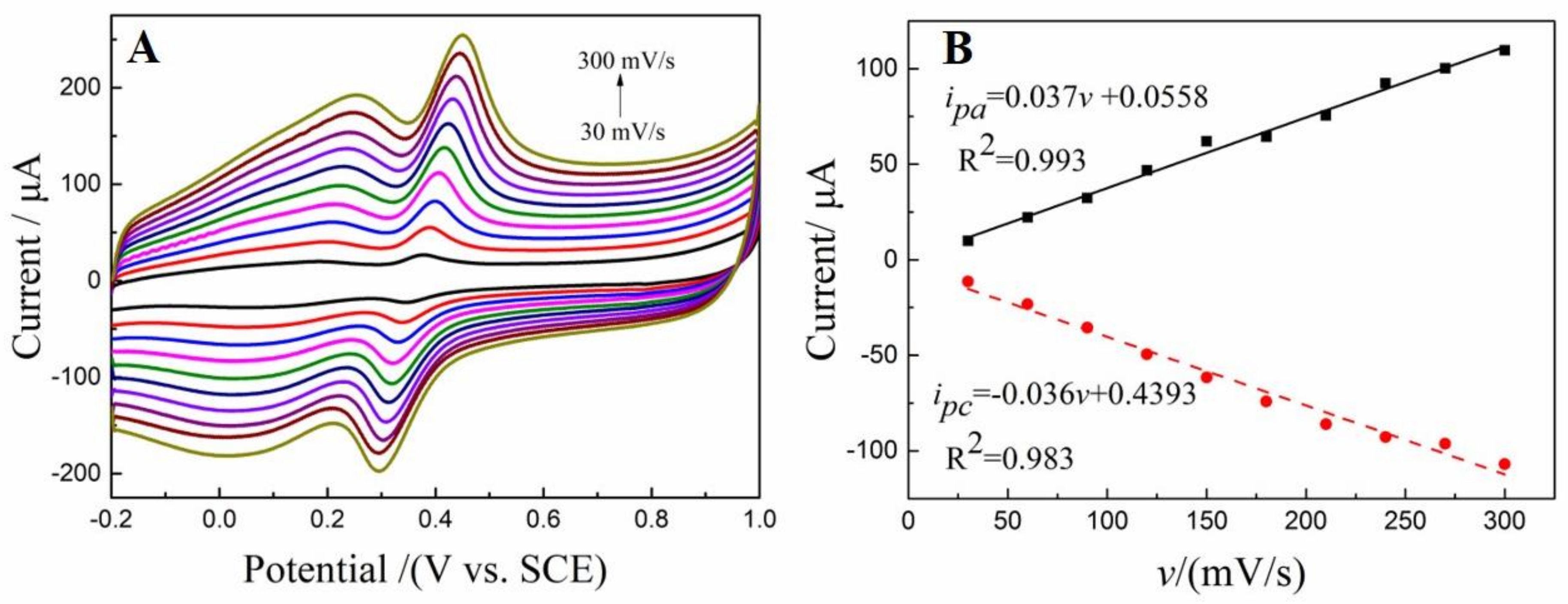
2.5. Electrochemical Kinetics of Dopamine on MnO2 NWs-RGO/GCE

Cyclic voltammograms of 1 × 10⁻⁵ mol/L dopamine on the MnO2 NWs-RGO/GCE were recorded at various scanning rates, and the results are shown in Figure 5A. It is observed that a pair of redox peaks appear on the MnO2 NWs-RGO/GCE. With the increasing of scanning rates, the oxide peak currents shift toward a positive direction while the reduction peak currents shift negatively. In other words, the peak separation increases with the scanning speed, suggesting the electrochemical oxidation of dopamine on the MnO2 NWs-RGO/GCE is a quasi-reversible process. As presented in Figure 5B, the oxidation peak currents (ipa) increase linearly with scanning rate (v), suggesting the electrochemical oxidation of dopamine is an adsorption-controlled process. This result is consistent with previous reports [34,37,38,39,40,41], and also favors our assumption for model simulation.

2.6. Electrochemical Sensing Perfomances of MnO2 NWs-RGO/GCE

The pH of supporting electrolytes plays an important role in the electrochemical oxidation of dopamine, so the pH dependence of the dopamine response was also investigated. As shown in Figure 6, the maximum response peak current was obtained at pH 3.0. Hence, pH 3.0 is selected for quantitative analysis. Since dopamine oxidation is an adsorption-controlled process, accumulation was often used to improve the sensitivity. The electrochemical sensing performances of MnO2 NWs-RGO/GCE were investigated using second-order derivative linear sweep voltammetry, and the results have been published in Chinese Journal of Analytic Chemistry [48]. The MnO2 NWs-RGO/GCE exhibits two linear response ranges (6 × 10⁻⁸ mol/L–1 × 10−6 mol/L and 1 × 10⁻⁶ mol/L–8 × 10−5 mol/L) and a low detection limit (S/N = 3, 1.0 × 10⁻⁹ mol/L) towards dopamine detection. A comparison of the electrochemical sensing performance between the MnO2 NWs-RGO/GCE and previous reports is summarized in Table 2. Remarkably, the detection performance of the MnO2 NWs-RGO/GCE is comparably even better than previous reports [16,28,33,49,50,51,52,53]. Last but not least, the linear response ranges basically overlap with the physiological level of dopamine (generally 10−6 mol/L to 10−8 mol/L [54]), indicating that MnO2 NWs-RGO/GCE shows great prospects for dopamine detection in various real samples such as brain fluids, blood serum, and urine. The MnO2 NWs-RGO/GCEs were successfully applied to detect dopamine in dopamine hydrochloride injection samples with a recovery rate of 99.6%~103%. Together with low cost, rapidness, and simplicity, the MnO2 NWs-RGO/GCEs are expected to detect dopamine in various real samples.

3. Materials and Methods

3.1. Materials and Chemicals

Graphite powder, potassium permanganate (KMnO4), manganese sulfate monohydrate (MnSO4·H2O), ammonium persulfate ((NH4)2S2O8), concentrated sulfuric acid (H2SO4), concentrated hydrochloric acid (HCl), hydrogen peroxide (H2O2), potassium ferricyanide (K3[Fe(CN)6]), potassium ferrocyanide (K4[Fe(CN)6]), sodium dihydrogen phosphate (NaH2PO4), disodium hydrogen phosphate (Na2HPO4), sodium hydroxide (NaOH), and ethyl alcohol were analytical grade and purchased from Sinopharm Chemical Reagent Co., Ltd. (Shanghai, China). Dopamine was purchased from Sigma-Aldrich Co (St. Louis, CA, USA). All these reagents were used as received without further purification, and deionized water was used throughout the experiments.

3.2. Preparation of Nano-MnO2 with Various Morphologies

3.2.1. Preparation of MnO2 NRs

To begin, 0.1 mol MnSO4·H2O and 0.1 mol KMnO4 were dissolved in 30 mL of deionized water. Then, 1 mL of 60% H2SO4 was added into the above mixture solution and stirred for 30 min, afterwards the mixture solution was transferred to a Teflon-lined stainless-steel autoclave and reacted at 150 °C for 30 min. The resulting product was centrifuged at 8000 rpm for 30 min, washed alternately by deionized water and ethanol three times, and vacuum-dried at 60 °C to obtain MnO2 NRs. Finally, MnO2 NRs were dispersed into deionized water to form 1 mg/mL dispersion solution.

3.2.2. Preparation of MnO2 NTs

Firstly, 0.45 g KMnO4 and 1 mL of concentrated hydrochloric acid was added into 40 mL of deionized water, then the mixture solution was stirred for 20 min. Afterwards the reaction solution was transferred into a Teflon-lined stainless-steel autoclave and autoclaved at 80 °C for 10 h. The resulting product was centrifuged at 8000 rpm for 30 min, washed repeatedly three times with deionized water and ethanol, and dried under vacuum at 60 °C to obtain MnO2 NTs. Finally, MnO2 NTs were dispersed into deionized water to form 1 mg/mL dispersion solution.

3.2.3. Preparation of MnO2 NWs

Briefly, 0.008 mol MnSO4·H2O and 0.015 mol (NH4)2S2O8 were dissolved into 35 mL of deionized water, and the mixture was sealed into to a Teflon-lined stainless-steel autoclave and reacted at 120 °C for 10 h. The as-obtained product was centrifuged at 8000 rpm for 30 min, washed repeatedly three times with deionized water and ethanol, and vacuum-dried at 60 °C to obtain MnO2 NWs. Finally, MnO2 NWs were dispersed into deionized water to obtain 1 mg/mL dispersion solution.

3.3. Preparation of MnO2-GO Nanocomposite Dispersion

GO was prepared from cheap graphite powder by modified Hummers method referred to our previous reports [36,37,38]. The resulting GO was dispersed in 100 mL of deionized water under ultrasonication for 2 h, centrifuged twice at 6000 rpm to remove trace precipitates, and the supernatant was taken out to obtain a gold GO solution with approximately 1 mg/mL. Then, 1 mL of MnO2 NRs, MnO2 NTs, and MnO2 NWs dispersion (1 mg/mL) was added into 20 mL GO dispersion (1 mg/mL) and ultrasonicated for 2 h to obtain the corresponding nano-MnO2-GO dispersion.

3.4. Fabrication of MnO2-RGO Modified Electrodes

Prior to electrode modification, the bare glassy carbon electrodes (GCEs) were polished to form mirror-like surfaces with 0.05 μm Al2O3 fine particles. Then the polished GCEs were subjected to ultrasonication in deionized water and absolute ethanol (each for 1 min), and dried by pure N2 gas. 5 μL of nano-MnO2-GO dispersions were dropped on the surface of the GCEs, and dried with an infrared lamp to obtain nano MnO2-GO modified glass carbon electrodes (i.e., MnO2 NRs-GO/GCEs, MnO2 NRs-GO/GCEs, and MnO2 NRs-GO/GCEs). Afterwards the MnO2-GO/GCEs were electrochemically reduced into MnO2-RGO/GCEs by the potentiostatic method. Specifically, the nano-GO/GCEs was immersed into 0.1mol/L PBS solution (pH 7.0), and then electrochemically reduced at a fixed potential of −1.5 V for 120 s. For comparison, RGO modified glass carbon electrodes (RGO/GCE) were fabricated by similar method.

3.5. Electrochemical Measurements

All the electrochemical experiments were carried out with standard three-electrode setup, consisting of bare GCEs, RGO/GCEs, or MnO2-RGO/GCEs as working electrode, a saturated calomel electrode (SCE) as reference electrode, and platinum wire electrode acted as auxiliary electrode. The electrochemical responses of 10 μM dopamine on the different electrodes were evaluated by second-order derivative linear sweep voltammetry. The electrochemical active areas of MnO2 NWs-RGO/GCEs, MnO2 NTs-RGO/GCEs, and MnO2 NRs-RGO/GCEs were estimated by recording cyclic voltammograms in 1 mM [Fe(CN)6]3−/4− probe solution.

4. Conclusions

In this study, three different morphologies of MnO2 nanomaterials (MnO2 NWs, MnO2 NTs, and MnO2 NRs) were prepared and then composited with GO to obtain MnO2-RGO counterparts. MnO2-RGO/GCE were fabricated by drop-casting MnO2-RGO dispersion on the surface of polished GCE and subsequent electrochemical reduction method. Both the response peak currents and electrochemical active areas increase in the following order of MnO2 NWs-RGO/GCE, MnO2 NTs-RGO/GCE, and MnO2 NRs-RGO/ GCE, while the response peak current densities increase in the reverse order. Morphology-dependent electrochemical sensing properties toward dopamine were well explained by establishing spatial models for MnO2 NWs, MnO2 NTs, and MnO2 NRs. By comparing the specific surface areas of these three morphologies of MnO2 nanomaterials, the enhancement of response peak currents mainly arises from the specific surface area, dominating by length to diameter ratio. The higher length to diameter ratio favors the electrochemical sensing toward dopamine, which provides valuable technical guidance for the development of novel electrode modification materials. The MnO2 NWs/GCE was chosen for detection of dopamine due to having the largest response peak current. The MnO2 NWs/GCEs exhibit wide linear dynamic ranges (6.0 × 10⁻⁸ mol/L ~ 1.0 × 10⁻⁶ mol/L and 1.0 × 10⁻⁶ mol/L ~ 8.0 × 10⁻⁵ mol/L) and a low detection limit (1 × 10⁻⁹ mol/L). Finally, MnO2 NWs-RGO/GCEs were successfully used for the determination of dopamine injection samples with satisfactory results.

Author Contributions

Q.H., P.D., G.L., and D.C. conceived and designed the experiments; J.L., X.L., and L.J. performed the experiments; G.L. and X.L. analyzed the data; Q.H. and D.C. contributed reagents/materials/analysis tools; G.L. and J.L. wrote the paper.

Funding

This research was funded by the NSFC (61703152), Hunan Provincial Natural Science Foundation (2016JJ4010 and 2018JJ3134), Project of Science and Technology Department of Hunan Province (GD16K02), The key Project of Department of Education of Guangdong Province (2016GCZX008), Project of Science and Technology Plan in Zhuzhou (201706-201806) and Opening Project of Key Discipline of Materials Science in Guangdong (CNXY2017001, CNXY2017002 and CNXY2017003). The APC was funded by Opening Project of Key Discipline of Materials Science in Guangdong (CNXY2017001, CNXY2017002 and CNXY2017003).

Conflicts of Interest

The authors declare no conflict of interest.

References

  1. Cai, W.; Lai, T.; Du, H.; Ye, J. Electrochemical determination of ascorbic acid, dopamine and uric acid based on an exfoliated graphite paper electrode: A high performance flexible sensor. Sens. Actuators B 2014, 193, 492–500. [Google Scholar] [CrossRef]
  2. Hsu, M.S.; Chen, Y.L.; Lee, C.Y.; Chiu, H.T. Gold nanostructures on flexible substrates as electrochemical dopamine sensors. ACS Appl. Mater. Interfaces 2012, 4, 5570–5575. [Google Scholar] [CrossRef] [PubMed]
  3. Gao, F.; Cai, X.; Wang, X.; Gao, C.; Liu, S.; Gao, F.; Wang, Q. Highly sensitive and selective detection of dopamine in the presence of ascorbic acid at graphene oxide modified electrode. Sens. Actuators B 2013, 186, 380–387. [Google Scholar] [CrossRef]
  4. Wang, C.; Yuan, R.; Chai, Y.; Zhang, Y.; Hu, F.; Zhang, M. Au-nanoclusters incorporated 3-amino-5-mercapto-1,2,4-triazole film modified electrode for the simultaneous determination of ascorbic acid, dopamine, uric acid and nitrite. Biosens. Bioelectron. 2011, 30, 315–319. [Google Scholar] [CrossRef] [PubMed]
  5. He, Q.; Liu, J.; Liang, J.; Liu, X.; Li, W.; Liu, Z.; Ding, Z.; Tuo, D. Towards Improvements for Penetrating the Blood–Brain Barrier—Recent Progress from a Material and Pharmaceutical Perspective. Cells 2018, 7, 24. [Google Scholar] [CrossRef] [PubMed]
  6. Carrera, V.; Sabater, E.; Vilanova, E.; Sogorb, M.A. A simple and rapid HPLC-MS method for the simultaneous determination of epinephrine, norepinephrine, dopamine and 5-hydroxytryptamine: Application to the secretion of bovine chromaffin cell cultures. J. Chromatogr. B 2007, 847, 88–94. [Google Scholar] [CrossRef] [PubMed]
  7. Wang, H.Y.; Sun, Y.; Tang, B. Study on fluorescence property of dopamine and determination of dopamine by fluorimetry. Talanta 2002, 57, 899–907. [Google Scholar] [CrossRef]
  8. Schöning, M.J.; Jacobs, M.; Muck, A.; Knobbe, D.T.; Wang, J.; Chatrathi, M.; Spillmann, S. Amperometric pdms/glass capillary electrophoresis-based biosensor microchip for catechol and dopamine detection. Sens. Actuators B 2005, 108, 688–694. [Google Scholar] [CrossRef]
  9. Li, X.; Pan, J.; Yang, F.; Feng, J.; Mo, J.; Chen, Z. Simple amperometric detector for microchip capillary electrophoresis, and its application to the analysis of dopamine and catechol. Microchim. Acta 2011, 174, 123–130. [Google Scholar] [CrossRef]
  10. Li, L.; Liu, H.; Shen, Y.; Zhang, J.; Zhu, J.J. Electrogenerated chemiluminescence of Au nanoclusters for the detection of dopamine. Anal. Chem. 2011, 83, 661–665. [Google Scholar] [CrossRef] [PubMed]
  11. Chen, L.; Lu, L.; Mo, Y.; Xu, Z.; Xie, S.; Yuan, H.; Xiao, D.; Choi, M.M. Electrogenerated chemiluminescence of anatase TiO2; nanotubes film. Talanta 2011, 85, 56–62. [Google Scholar] [CrossRef] [PubMed]
  12. Yan, J.; Liu, S.; Zhang, Z.; He, G.; Zhou, P.; Liang, H.; Tian, L.; Zhou, X.; Jiang, H. Simultaneous electrochemical detection of ascorbic acid, dopamine and uric acid based on graphene anchored with Pd–Pt nanoparticles. Colloids Surf. B 2013, 111, 392–397. [Google Scholar] [CrossRef] [PubMed]
  13. Huang, Y.; Miao, Y.E.; Ji, S.; Weng, W.T.; Liu, T. Electrospun carbon nanofibers decorated with Ag–Pt bimetallic nanoparticles for selective detection of dopamine. ACS Appl. Mater. Interfaces 2014, 6, 12449–12456. [Google Scholar] [CrossRef] [PubMed]
  14. Ahn, M.; Kim, J. Electrochemical behavior of dopamine and ascorbic acid at dendritic au rod surfaces: Selective detection of dopamine in the presence of high concentration of ascorbic acid. J. Electroanal. Chem. 2012, 683, 75–79. [Google Scholar] [CrossRef]
  15. Fang, B.; Wang, G.; Zhang, W.; Li, M.; Kan, X. Fabrication of Fe3O4 nanoparticles modified electrode and its application for voltammetric sensing of dopamine. Electroanalysis 2010, 17, 744–748. [Google Scholar] [CrossRef]
  16. Wu, L.N.; Tan, Y.L.; Wang, L.; Sun, S.N.; Qu, Z.Y.; Zhang, J.M.; Fan, Y.J. Dopamine sensor based on a hybrid material composed of cuprous oxide hollow microspheres and carbon black. Microchim. Acta 2015, 182, 1361–1369. [Google Scholar] [CrossRef]
  17. Wang, Q.; Tang, Q.L. Improved sensing of dopamine and ascorbic acid using a glassy carbon electrode modified with electrochemically synthesized nickel-cobalt hexacyanoferrate microparticles deposited on graphene. Microchim. Acta 2015, 182, 671–677. [Google Scholar] [CrossRef]
  18. Yuan, B.; Xu, C.; Liu, L.; Zhang, Q.; Ji, S.; Pi, L.; Zhang, D.; Huo, Q. Cu2O/NiOx/graphene oxide modified glassy carbon electrode for the enhanced electrochemical oxidation of reduced glutathione and nonenzyme glucose sensor. Electrochim. Acta 2013, 104, 78–83. [Google Scholar] [CrossRef]
  19. Jiao, F.; Bruce, P.G. Mesoporous Crystalline β-MnO2—A Reversible Positive Electrode for Rechargeable Lithium Batteries. Adv. Mater. 2010, 19, 657–660. [Google Scholar] [CrossRef]
  20. Li, Q.; Lu, X.F.; Xu, H.; Tong, Y.X.; Li, G.R. Carbon/MnO2 double-walled nanotube arrays with fast ion and electron transmission for high-performance supercapacitors. ACS Appl. Mater. Interfaces 2014, 6, 2726–2733. [Google Scholar] [CrossRef] [PubMed]
  21. Guo, M.; Bian, S.; Shao, F.; Liu, S.; Peng, Y. Hydrothermal synthesis and electrochemical performance of MnO2/graphene/polyester composite electrode materials for flexible supercapacitors. Electrochim. Acta 2016, 209, 486–497. [Google Scholar] [CrossRef]
  22. Chen, K.; Wang, M.; Li, G.; He, Q.; Liu, J.; Li, F. Spherical α-MnO2 supported on N-KB as efficient electrocatalyst for oxygen reduction in Al–air battery. Materials 2018, 11, 601. [Google Scholar] [CrossRef] [PubMed]
  23. Wang, M.; Chen, K.; Liu, J.; He, Q.; Li, G.; Li, F. Efficiently enhancing electrocatalytic activity of α-MnO2 nanorods/N-doped ketjenblack carbon for oxygen reduction reaction and oxygen evolution reaction using facile regulated hydrothermal treatment. Catalysts 2018, 8, 138. [Google Scholar] [CrossRef]
  24. Mahmoudian, M.R.; Alias, Y.; Basirun, W.J.; Pei, M.W.; Sookhakian, M. Facile preparation of MnO2 nanotubes/reduced graphene oxide nanocomposite for electrochemical sensing of hydrogen peroxide. Sens. Actuators B 2014, 201, 526–534. [Google Scholar] [CrossRef]
  25. Zhang, L.; Liu, Z.; Hao, L.; Tang, X.; Kenta, O. Shape-controllable synthesis and electrochemical properties of nanostructured manganese oxides. J. Phys. Chem. C 2007, 111, 8418–8423. [Google Scholar] [CrossRef]
  26. Wu, Z.L.; Li, C.K.; Yu, J.G.; Chen, X.Q. MnO2 /reduced graphene oxide nanoribbons: Facile hydrothermal preparation and their application in amperometric detection of hydrogen peroxide. Sens. Actuators B 2017, 239, 544–552. [Google Scholar] [CrossRef]
  27. Yang, L.; Liu, D.; Huang, J.; You, T. Simultaneous determination of dopamine, ascorbic acid and uric acid at electrochemically reduced graphene oxide modified electrode. Sens. Actuators B 2014, 193, 166–172. [Google Scholar] [CrossRef]
  28. Huang, Y.; Cheng, C.; Tian, X.; Zheng, B.; Li, Y.; Yuan, H.; Xiao, D.; Choi, M.M.F. Low-potential amperometric detection of dopamine based on MnO2 nanowires/chitosan modified gold electrode. Electrochim. Acta 2013, 89, 832–839. [Google Scholar] [CrossRef]
  29. Bai, Y.; Xu, J.; Chen, H. Selective sensing of cysteine on manganese dioxide nanowires and chitosan modified glassy carbon electrodes. Biosens. Bioelectron. 2009, 24, 2985–2990. [Google Scholar] [CrossRef] [PubMed]
  30. Sivasubramanian, R.; Biji, P. Preparation of copper (I) oxide nanohexagon decorated reduced graphene oxide nanocomposite and its application in electrochemical sensing of dopamine. Mater. Sci. Eng. B 2016, 210, 10–18. [Google Scholar] [CrossRef]
  31. Zhang, X.; Zhang, Y.C.; Ma, L.X. One-pot facile fabrication of graphene-zinc oxide composite and its enhanced sensitivity for simultaneous electrochemical detection of ascorbic acid, dopamine and uric acid. Sens. Actuators B 2016, 227, 488–496. [Google Scholar] [CrossRef]
  32. Wang, Z.H.; Tang, J.; Zhang, F.F.; Xia, J.F.; Sun, N.; Shi, G.Y.; Xia, Y.Z.; Xia, L.H.; Qin, L.C. Elimination of ascorbic acid and sensitive detection of uric acid at the MnO2 nanorods/graphene-based modified electrode. Int. J. Electrochem. Sci. 2013, 8, 9967–9976. [Google Scholar]
  33. Yang, B.; Wang, J.; Duan, B.; Zhu, M.; Yang, P.; Du, Y. A three dimensional Pt nanodendrite/graphene/MnO2 nanoflower modified electrode for the sensitive and selective detection of dopamine. J. Mater. Chem. B 2015, 3, 7440–7448. [Google Scholar] [CrossRef]
  34. Chen, A.; Xu, L.; Zhang, X.; Yang, Z.; Yang, S. Improving surface adsorption via shape control of hematite α-Fe2O3 nanoparticles for sensitive dopamine sensors. ACS Appl. Mater. Interfaces 2016, 8, 33765–33774. [Google Scholar] [CrossRef] [PubMed]
  35. Gan, T.; Shi, Z.; Deng, Y.; Sun, J.; Wang, H. Morphology–dependent electrochemical sensing properties of manganese dioxide–graphene oxide hybrid for guaiacol and vanillin. Electrochim. Acta 2014, 147, 157–166. [Google Scholar] [CrossRef]
  36. He, Q.; Liu, J.; Liu, X.; Li, G.; Deng, P.; Liang, J.; Chen, D. Sensitive and selective detection of tartrazine based on TiO2-electrochemically reduced graphene oxide composite-modified electrodes. Sensors 2018, 18, 1911. [Google Scholar] [CrossRef] [PubMed]
  37. He, Q.; Liu, J.; Liu, X.; Li, G.; Chen, D.; Deng, P.; Liang, J. Fabrication of amine-modified magnetite-electrochemically reduced graphene oxide nanocomposite modified glassy carbon electrode for sensitive dopamine determination. Nanomaterials 2018, 8, 194. [Google Scholar] [CrossRef] [PubMed]
  38. He, Q.; Liu, J.; Liu, X.; Li, G.; Deng, P.; Liang, J. Preparation of Cu2O-reduced graphene nanocomposite modified electrodes towards ultrasensitive dopamine detection. Sensors 2018, 18, 199. [Google Scholar] [CrossRef] [PubMed]
  39. Liu, A.; Honma, I.; Zhou, H. Simultaneous voltammetric detection of dopamine and uric acid at their physiological level in the presence of ascorbic acid using poly(acrylic acid)-multiwalled carbon-nanotube composite-covered glassy-carbon electrode. Biosens. Bioelectron. 2008, 23, 74–80. [Google Scholar] [CrossRef] [PubMed]
  40. Wu, K.; Fei, J.; Hu, S. Simultaneous determination of dopamine and serotonin on a glassy carbon electrode coated with a film of carbon nanotubes. Anal. Biochem. 2003, 318, 100–106. [Google Scholar] [CrossRef]
  41. Wu, L.; Feng, L.; Ren, J.; Qu, X. Electrochemical detection of dopamine using porphyrin-functionalized graphene. Biosens. Bioelectron. 2012, 34, 57–62. [Google Scholar] [CrossRef] [PubMed]
  42. Bard, A.J.; Faulkner, L.R.; Bard, A.; Faulkner, L. Electrochemical Methods: Fundamentals and Applications; Wiley: New York, NY, USA, 2001; pp. 669–676. [Google Scholar]
  43. Gooding, J.J.; Praig, V.G.; Hall, E.A. Platinum-catalyzed enzyme electrodes immobilized on gold using self-assembled layers. Anal. Chem. 1998, 70, 2396–2402. [Google Scholar] [CrossRef] [PubMed]
  44. Li, J.; Qu, Z.; Qin, Y.; Wang, H. Effect of MnO2 morphology on the catalytic oxidation of toluene over Ag/MnO2 catalysts. Appl. Surf. Sci. 2016, 385, 234–240. [Google Scholar] [CrossRef]
  45. Laviron, E. Adsorption, autoinhibition and autocatalysis in polarography and in linear potential sweep voltammetry. J. Electroanal. Chem Interfacial Electrochem. 1974, 52, 355–393. [Google Scholar] [CrossRef]
  46. Wang, Z.L. Nanowires and Nanobelts; Springer: Boston, MA, USA, 2004; Volume 2, pp. 657–661. [Google Scholar]
  47. Hassanpour, A.; Bogdan, N.; Capobianco, J.A.; Bianucci, P. Hydrothermal selective growth of low aspect ratio isolated ZnO nanorods. Mater. Des. 2017, 119, 464–469. [Google Scholar] [CrossRef]
  48. He, Q.; Liang, J.; Li, G.; Deng, P.; Liu, J.; Liu, X. Electrochemical detection of dopamine based on MnO2 nanowires/reduced graphene oxide composites modified glassy carbon electrode. Chin. J. Anal. Chem. 2018, 46, 438–445. [Google Scholar]
  49. Reddy, S.; Swamy, B.E.K.; Jayadevappa, H. CuO nanoparticle sensor for the electrochemical determination of dopamine. Electrochim. Acta 2012, 61, 78–86. [Google Scholar] [CrossRef]
  50. Yao, Z.; Yang, X.; Niu, Y.; Wu, F.; Hu, Y.; Yang, Y. Voltammetric dopamine sensor based on a gold electrode modified with reduced graphene oxide and Mn3O4 on gold nanoparticles. Microchim. Acta 2017, 184, 1–8. [Google Scholar] [CrossRef]
  51. Reddy, S.; Swamy, B.E.K.; Chandrashekar, B.N.; Chitravathi, S.; Jayadevappa, H. Cationic surfactants–assisted synthesis of ZnO nanoparticles and their modified carbon paste electrode for electrochemical investigation of dopamine. Anal. Bioanal. Electrochem. 2012, 4, 186–196. [Google Scholar]
  52. Gao, W.; Ye, S.; Shao, M. Solution-combusting preparation of mono-dispersed Mn3O4 nanoparticles for electrochemical applications. J. Phys. Chem. Solids 2011, 72, 1027–1031. [Google Scholar] [CrossRef]
  53. Adekunle, A.S.; Agboola, B.O.; Pillay, J.; Ozoemena, K.I. Electrocatalytic detection of dopamine at single-walled carbon nanotubes–iron (iii) oxide nanoparticles platform. Sens. Actuators B 2010, 148, 93–102. [Google Scholar] [CrossRef]
  54. Liu, A.; Honma, I.; Zhou, H. Amperometric biosensor based on tyrosinase-conjugated polysacchride hybrid film: Selective determination of nanomolar neurotransmitters metabolite of 3,4-dihydroxyphenylacetic acid (dopac) in biological fluid. Biosens. Bioelectron. 2006, 21, 809–816. [Google Scholar] [CrossRef] [PubMed]
Figure 1. The scanning electron microscopy (SEM) images of MnO2 nanomaterials and corresponding MnO2-reduced graphene oxide (RGO) nanocomposites. (A): MnO2 nanorods (NRs); (B): MnO2 nanotubes (NTs); (C): MnO2 nanowires (NWs); (D): MnO2 NRs/RGO; (E): MnO2 NTs/RGO; (F): MnO2 NWs/RGO.
Catalysts 08 00323 g001
Figure 2. X-ray diffraction (XRD) patterns of MnO2 NWs, MnO2 NRs, and MnO2 NTs.
Catalysts 08 00323 g002
Figure 3. Cyclic voltammograms of MnO2 NWs-RGO/ glass carbon electrode (GCE), MnO2 NRs-RGO/GCE, and MnO2 NTs-RGO/GCE in 1.0 × 10⁻³ mol/L [Fe(CN)6]3−/4− probe solution (scan rate: 0.05 V·s−1; supporting electrolytes: 0.1 mol/L pH 3.0 PBS).
Catalysts 08 00323 g003
Figure 4. Spatial models for MnO2 NWs (A), MnO2 NTs (B), and MnO2 NRs (C).
Catalysts 08 00323 g004
Figure 5. (A) The cyclic voltammograms of dopamine on the MnO2 NWs-RGO/GCE at different scanning rates; (B) Relationship between oxidation peak current (ipa) and scanning rate (v).
Catalysts 08 00323 g005
Figure 6. Effect of pH on the response peak current of 1 × 10⁻⁵ mol/L dopamine on the MnO2 NWs-RGO/GCE.
Catalysts 08 00323 g006
Table 1. The second-order derivative linear sweep voltammetric (SDLSV) response of dopamine on the different electrodes a.
ElectrodesEpa/mV bIpa/μA cJpac/(μA/cm2) d
Bare GCE3921.396——
RGO/GCE44422.56——
MnO2 NRs-RGO/GCE45225.74272.13
MnO2 NTs-RGO/GCE45227.86265.33
MnO2 NWs-RGO/GCE44030.26232.77
a The second-order derivative linear sweep voltammetry for the bare GCE, RGO/GCE, MnO2 NRs-RGO/GCE, MnO2 NTs-RGO/GCE and MnO2 NWs were recorded in the 0.1 mol/L PBS containing 1 × 10⁻⁵ mol/L dopamine at 100 mV/s. b Epa denotes oxidation peak current. c Ipa denotes oxidation peak current. d Jpa denotes oxidation peak current density.
Table 2. Comparison of the electrochemical sensing performances between the MnO2 NWs-RGO/GCE and previous reports.
ElectrodesMethodLinear Range (μM)Detection Limit (μM)Ref.
MnO2 nanowires/chitosan-modifed gold electrodeCA a0.10–12.00.04[28]
ZnO-modified carbon paste electrodeDPV b0.1–200.03[51]
Cu2O/graphene-modified glassy carbon electrodeCV c0.3–1.4;
2–20
0.055[16]
CuO-modified carbon paste electrodeDPV b0.1–100.01[49]
Mn3O4-modified graphite electrodeDPV b10–700.1[52]
SWCNT/Fe2O3-modified graphite electrodeSWV d3.2–31.80.36[53]
rGO-Mn3O4/Nafion film supporting Au nanoparticles modified gold electrodeCA a1.0–14500.25[50]
Pt nanodendrites/reduce graphene oxide/MnO2 nanoflowers modified glassy carbon electrodeDPV b1.5–215.560.1[33]
MnO2 NWs-ErGO/GCESDLSV e0.06–1.0
1.0–80
0.001This work
a CA: chronoamperometry. b DPV: differential pulse voltammetry. c CV: cyclic voltammetry. d SWV: square wave voltammetry. e SDLSV: second-order derivative linear sweep voltammetry.

