Highly Dispersed Co Nanoparticles Prepared by an Improved Method for Plasma-Driven NH3 Decomposition to Produce H2


1
College of Environmental Science and Engineering, Dalian Maritime University, Dalian 116026, China
2
State Key Laboratory of Fine Chemicals, School of Chemical Engineering, Dalian University of Technology, Dalian 116024, China
*
Authors to whom correspondence should be addressed.
Catalysts 2019, 9(2), 107; https://doi.org/10.3390/catal9020107
Submission received: 3 December 2018
/
Revised: 10 January 2019
/
Accepted: 17 January 2019
/
Published: 22 January 2019
(This article belongs to the Special Issue Plasma Catalysis)
Abstract
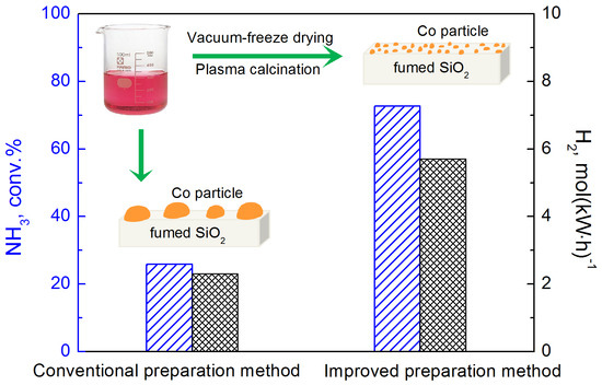
:Previous studies reveal that combining non-thermal plasma with cheap metal catalysts achieved a significant synergy of enhancing performance of NH3 decomposition, and this synergy strongly depended on the properties of the catalyst used. In this study, techniques of vacuum-freeze drying and plasma calcination were employed to improve the conventional preparation method of catalyst, aiming to enhance the activity of plasma-catalytic NH3 decomposition. Compared with the activity of the catalyst prepared by a conventional method, the conversion of NH3 significantly increased by 47% when Co/fumed SiO2 was prepared by the improved method, and the energy efficiency of H2 production increased from 2.3 to 5.7 mol(kW·h)−1 as well. So far, the highest energy efficiency of H2 formation of 15.9 mol(kW·h)−1 was achieved on improved prepared Co/fumed SiO2 with 98.0% ammonia conversion at the optimal conditions. The improved preparation method enables cobalt species to be highly dispersed on fumed SiO2 support, which creates more active sites. Besides, interaction of Co with fumed SiO2 and acidity of the catalyst were strengthened according to results of H2-TPR and NH3-probe experiments, respectively. These results demonstrate that employing vacuum-freeze drying and plasma calcination during catalyst preparation is an effective approach to manipulate the properties of catalyst, and enables the catalyst to display high activity towards plasma-catalytic NH3 decomposition to produce H2.
1. Introduction
NH3 decomposition has been considered to be an attractive route to supply COx-free H2 for proton exchange membrane fuel cell (PEMFC) vehicles [1,2,3]. Until now, the noble metal Ru, due to its high turnover frequency (TOF), is still the most active component for NH3 decomposition, and the formation rate of H2 reached as high as 4.0 mol/(h·gcat)−1 using K-Ru/MgO-CNTs catalyst with complete conversion of ammonia at 450 °C, but the scarcity and high price of Ru limits its use on a large scale [4,5,6]. Whereas, cheap metal catalysts show low activity towards NH3 decomposition due to the strong adsorption of N atoms onto the surface of cheap metal catalysts [1,7,8,9,10]. As far as we know, the highest formation rate of H2 was 2.0 mol/(h·gcat)−1 using CeO2-doped Ni/Al2O3 catalyst with 98.3% ammonia conversion at 550 °C [7]. Recently, the combination of non-thermal plasma with cheap metal catalyst displayed a powerful ability in enhancing NH3 decomposition [11,12,13]; 99.9% conversion of NH3 was achieved in combination mode, but only 7.4% and 7.8% was obtained for Fe-based catalyst alone and plasma alone, respectively, which experienced an unexpected strong synergy between plasma and catalyst [11], and this synergy strongly depended on the properties of catalyst [12,14].
The preparation approach of catalyst could directly affect the properties of the catalyst, such as crystal size, shape, composition, acidity, and basicity [15,16,17]. Normally, catalyst preparation was operated in a thermodynamic equilibrium state of gas, liquid, and solid state, but faces the limitation of thermodynamic equilibrium. For example, the calcination temperature for supported metal catalysts is usually over 500 °C, and high temperature operation causes aggregation of metal particles, but low temperature operation results in incomplete decomposition of catalyst precursors. Besides, it is difficult to achieve a high dispersion of catalyst with a high metal loading above 20 wt % in a thermodynamic equilibrium state.
Non-thermal plasma is the fourth state of matter and characterized by non-equilibrium character. Typically, the overall gas temperature in a field of non-thermal plasma can be as low as room temperature, while the generated free electrons are highly energetic with a typical electron temperature of 1–10 eV, which can collide with carrier gas to produce chemically reactive species such as radicals, excited species, and ions [18]. Such a characteristic of plasma enables some thermodynamically unfavorable chemical reactions to proceed at moderate conditions, especially for inert molecule conversion, such as CO2, CH4, and N2 [19,20,21,22,23,24].
Similarly, the non-equilibrium character of non-thermal plasma also benefits catalyst preparation to achieve controllable morphology and chemical property by controlling the reaction rate of nucleation and crystal growth in a non-equilibrium environment. Different from the conventional thermal process, the catalyst preparation with plasma is not based on the thermal effect, but on the inelastic collision of those energetic species (free electrons, radicals, excited species and ions) with catalyst precursors to accomplish the purpose of calcination or treatment. Catalyst preparation with plasma has attracted increasing interest since the 1990s [25,26,27,28,29,30,31,32,33,34], and a variety of plasmas, such as glow discharge, radio frequency discharge, microwave discharge, and dielectric barrier discharge, were employed for calcination and reduction of supported catalyst, which can make metal highly dispersed on a support with a narrow distribution of particle size, manipulate metal–support interaction, and shorten the time of catalyst preparation due to high reaction rates in the plasma process. Besides, with regard to the characteristic of low temperature, plasma removal of template was well developed for synthesis of microporous and mesoporous materials, instead of thermal removal that could destroy the porous structure of the materials [35]. Bogaerts and coworkers found that plasma could be formed inside pores of material with pore size above 200 μm at 20 kV by two-dimensional fluid modeling, and the possibility of discharge forming inside pores and discharge behavior strongly depended on pore size and applied voltage [36]; this observation helps to understand the process of plasma removal of template. Very recently, Wang, et al. and Di, et al. summarized the advances in preparation of catalyst with plasmas, and the mechanism of preparation was discussed as well [29,30]. Although low temperature operation of non-thermal plasma enables catalyst preparation in a more efficient and more controllable way, normally, low temperature operation leads to incomplete decomposition or removal of precursors, along with poor growth of materials with residues.
In this study, a novel combination of vacuum-freeze drying technique with atmospheric pressure dielectric barrier discharge (DBD) calcination technique was proposed for the preparation of supported Co catalyst with a high Co loading of 30 wt %. To calcine catalyst completely, DBD reactor was placed in a furnace to prevent heat dissipation of electric heat from discharge, so as to keep plasma calcination at a temperature of about 400 °C by tuning energy input of power supply (note that the furnace here is not used to heat the reactor, but used for electric heat preservation). Compared to Co/fumed SiO2 with conventional preparation method, the improved preparation method enabled the conversion of plasma-catalytic NH3 to increase by 47%, and greatly enhanced the formation rate of H2. Besides, the reaction performance can be further improved through increasing specific energy input.
2. Results and Discussion
2.1. Characterization
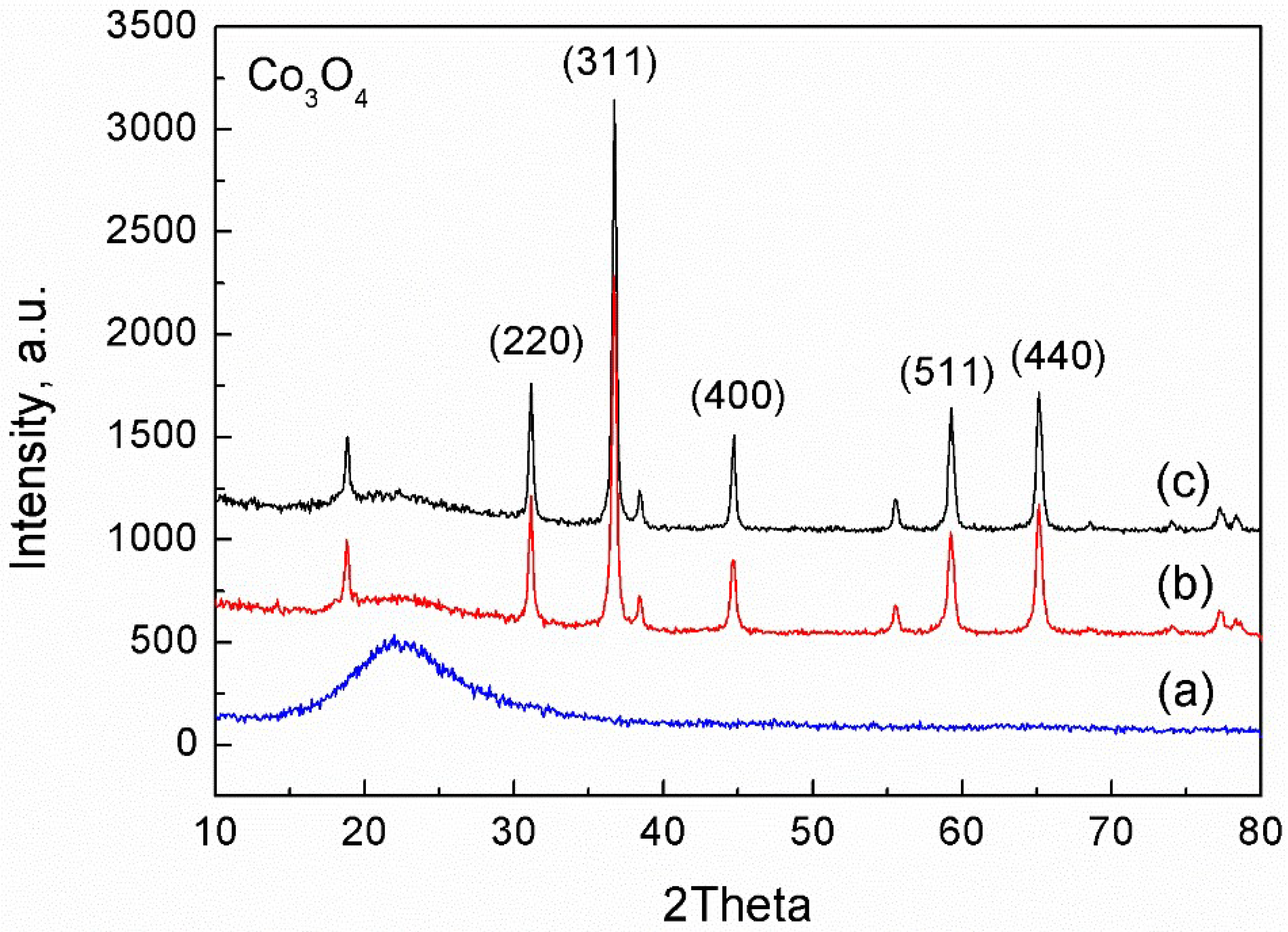
The physicochemical properties of as-prepared Co catalysts were examined using various characterization techniques, including X-ray diffraction (XRD), X-ray fluorescence (XRF), transmission electron microcopy (TEM), H2 temperature-programmed reduction (H2-TPR), and NH3 temperature-programmed desorption (NH3-TPD). In this study, the fumed SiO2 used as a support for Co catalyst was an amorphous material with a Brunauer–Emmett–Teller (BET) surface area of 297.8 m2·g−1. The theoretical Co loading was designed to be 30 wt %, but the actual Co loading through XRF analysis was 27.7 wt % and 27.4 wt % for the improved prepared catalyst and the conventional prepared catalyst, respectively (see Tables S1 and S2 in Supporting Information). Figure 1 shows the XRD patterns of as-prepared fumed SiO2-supported Co catalysts using conventional and improved preparation methods, respectively. Besides, pure fumed SiO2 was analyzed as a reference in Figure 1 (a). Clearly, the same diffraction peaks were observed at 2θ of 31.1, 36.7, 44.6, 59.2, and 65.2 as shown in Figure 1 (b) and (c), which matched well with the characteristic structure of Co3O4 (JCPDS file No: 43-1003), and those diffraction peaks represented the (220), (311), (400), (511), and (440) planes of Co3O4, respectively [37,38]. Namely, the difference in preparation approach did not influence the phase structure of Co catalysts, and they both finally existed in the form of Co3O4 over fumed SiO2 support. However, by contrast, the intensity of diffraction peaks of Co catalyst prepared with improved method was weaker than that with conventional preparation method, suggesting that the average particle size of the former is smaller than that of the latter according to the Debye–Scherrer formula [39]; this observation is also supported by the results of TEM as follows.
TEM images of as-prepared Co catalyst supported on fumed SiO2 using different approaches were shown in Figure 2. Clearly, a very poor dispersion of Co catalyst was observed on fumed SiO2 using the conventional preparation method, and the particle size of Co was much larger than 5 nm; some particle sizes were around 50 nm, as shown in Figure 2a,b. However, the use of combining vacuum-freeze drying and plasma calcination techniques in the process of catalyst preparation enabled the Co particles to disperse highly and homogeneously onto the fumed SiO2 support, and the average Co particle size was less than 5 nm, mostly around 2–3 nm in Figure 2c,d. Actually, it is difficult to obtain such smaller nanoparticles with a high metal loading of about 27 wt % using the conventional preparation method.
Using NH3 as probe molecule, the influence of preparation approach on the chemical properties of catalyst was evaluated through NH3-TPD, as displayed in Figure 3. Clearly, two major desorption peaks were observed, one at the low temperatures of 150–220 °C corresponded to the weak adsorption of NH3 on the catalyst, and the other at the high temperatures of 220–350 °C was attributed to the strong adsorption of NH3. It is worth noting that the desorption amount of NH3 over Co catalyst prepared with the improved method was much higher than that with the conventional preparation method, revealing that the improved method leads to an increase in the number of active sites for NH3 adsorption; this finding can be ascribed to the high dispersion of Co nanoparticles, as evidenced by the results of TEM in Figure 2. In addition, the desorption temperature of adsorbed NH3 on the catalyst with improved preparation method shifted towards higher temperature, reflecting that the binding ability of NH3 with the catalyst was stronger than that with the catalyst prepared using conventional preparation method. This inferred that the acidity of catalyst was strengthened by the improved preparation method as well and, more importantly, the increase in active site number and acid strength both facilitated the adsorption of NH3 on the catalyst, finally promoting the dissociation of NH3 on the catalyst.
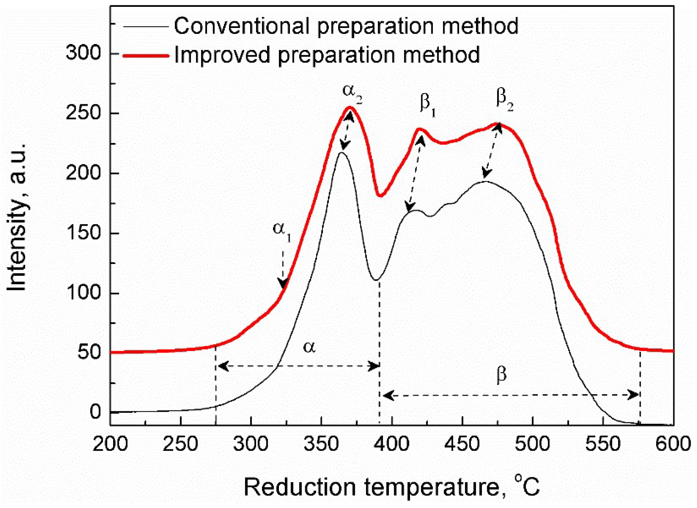
H2-TPR technique was used to evaluate the reduction behavior of Co3O4/fumed SiO2 prepared with different methods, and the resulting profiles are displayed in Figure 4. Clearly, the reduction of Co3O4 on fumed SiO2 support occurred in the temperature range of 275–550 °C. Two groups of reduction peaks were observed, i.e., the low temperature reduction peaks (α) consisted of α1 and α2 in the range of 275–400 °C, and the high temperature reduction peaks (β) with a consecutive-broad peak consisted of β1 and β2 in the range of 370–550 °C. More importantly, by contrast, the reduction temperature of catalyst with improved preparation method shifted towards higher temperature, representing that the improved method strengthened the interaction of Co with fumed SiO2 support. This difference in metal–support interaction can be explained by the difference in particle sizes of Co catalyst prepared by different methods (Figure 2). Actually, the reduction process of as-prepared catalyst was very complicated, since these peaks obtained were heavily overlapped. Therefore, the analysis of each peak area using peak fit function (Gaussian) of Origin software was employed to understand the H2-TPR profiles obtained (see Figure S1 in Supporting Information), the area ratio of β1/β2 was found to be 1/3, which is quantitatively consistent with the theoretical value (1/3) of area ratio of Co3O4 reduction peaks [40,41]. This indicates that β1 and β2 corresponded to the two-step reduction of Co3+ → Co2+ → Co0 of Co3O4, as do α1 and α2 based on 5/16 (≈ 1/3) area ratio of α1/α2. Besides, the result of XRD in Figure 1 also supported the assignment of α and β to Co3O4. According to the reduction temperature of Co3O4, the low temperature reduction peaks (α1 and α2) could be due to the reduction of bulk Co3O4, whereas the high temperature reduction peaks (β1 and β2) were attributed to the reduction of Co3O4 that interacted with fumed SiO2 [42,43].
Interestingly, the above results reveal that the application of vacuum-freeze drying and plasma calcination techniques in the preparation process of catalyst not only results in highly dispersed metal nanoparticles along with the increase of active site number, but also strengthens the acidity of catalyst and the metal–support interaction. Thus, it is feasible and crucial to manipulate the properties of catalysts through exploiting novel preparation techniques.
2.2. Performance of Prepared Catalyst in Plasma-Catalytic NH3 Decomposition
Our previous studies showed that Co-based catalyst exhibited the best activity towards NH3 decomposition to H2 in the presence of DBD plasma [12]. Here, the influence of catalyst preparation method on the performance of plasma-catalytic NH3 decomposition was investigated, as shown in Figure 5. Compared to the conventional preparation method, Co/fumed SiO2 catalyst prepared with the improved method greatly promoted the reaction performance, and the conversion of NH3 increased from 25.8 to 72.7% at the reaction temperature of 400 °C in Figure 5a, increased by a factor of almost 3 and, correspondingly, the energy efficiency of H2 formation increased from 2.3 to 5.7 mol(kW·h)−1 in Figure 5b. In addition, changing the reaction temperature from 300 °C to 450 °C through increasing DBD energy input resulted in a significant increase of NH3 conversion by 80.8% (from 16.1 to 96.9%) in the case of catalyst prepared by the improved method whereas, at the same conditions, the NH3 conversion only increased by 47.3% (from 4% to 51.3%) over catalyst using the conventional preparation method. Note that the reaction temperature required for complete conversion of NH3 in the case of using improved preparation method shifted towards lower temperature, at least 50 °C lower in comparison with that using conventional preparation method in Figure 5a.
Combining the results of characterizations in Figure 1 to 4, the improved preparation method did not affect the phase composition of catalyst (Figure 1), but significantly increased the dispersion of catalyst with a narrow particle size of 2–3 nm (Figure 2), which actually creates much more active sites for NH3 decomposition, enhancing the specific reactivity of catalyst, and this is also directly evidenced by the result of NH3-probe experiments presented in Figure 3. Notably, the adsorption amount of NH3 over the catalyst with improved preparation method is much larger than that with conventional preparation method (Figure 3), this directly points to the fact that enhancing the adsorption step of NH3 decomposition is one of the reasons for the high activity of catalyst with improved preparation method. Recently, CoPt/TiO2 with Co particle size of ~1 nm displayed a much higher Fischer–Tropsch reaction rate, which was also found to be due to increasing the amount of active site caused by using plasma-assisted preparation [44]. More importantly, in this study, the improved preparation method increased the acid strength of catalyst as well (Figure 3), as demonstrated by the increase in adsorption strength of NH3 over catalyst, which can promote the dissociation step of NH3; this is another crucial reason that explains the high activity of catalyst with the improved preparation method. Besides, the improved preparation method strengthened the interaction of Co with fumed SiO2 (Figure 4), indicating the difference in electronic structure of catalyst with different preparation methods, and this could influence the activity of catalyst as well.
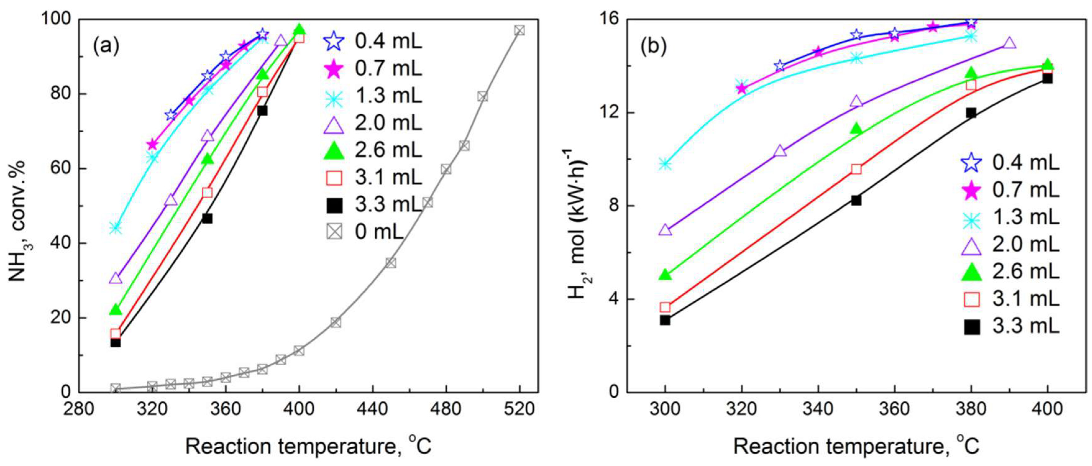
In addition, using Co/fumed SiO2 catalyst prepared by the improved method, the influence of the combining mode of plasma and catalyst was investigated on the performance of plasma-catalytic NH3 decomposition, as shown in Scheme 1 and Figure 6. About 3 g Co/fumed SiO2 was packed in the reactor with a packing volume of about 3.1 mL, and the combining mode of plasma and catalyst changed through changing discharge volume “V”, but the packed catalyst was fixed. Namely, changing “V” from 3.3 to 0.4 mL enabled the catalyst to be partly packed in the field of plasma, as shown in Scheme 1.
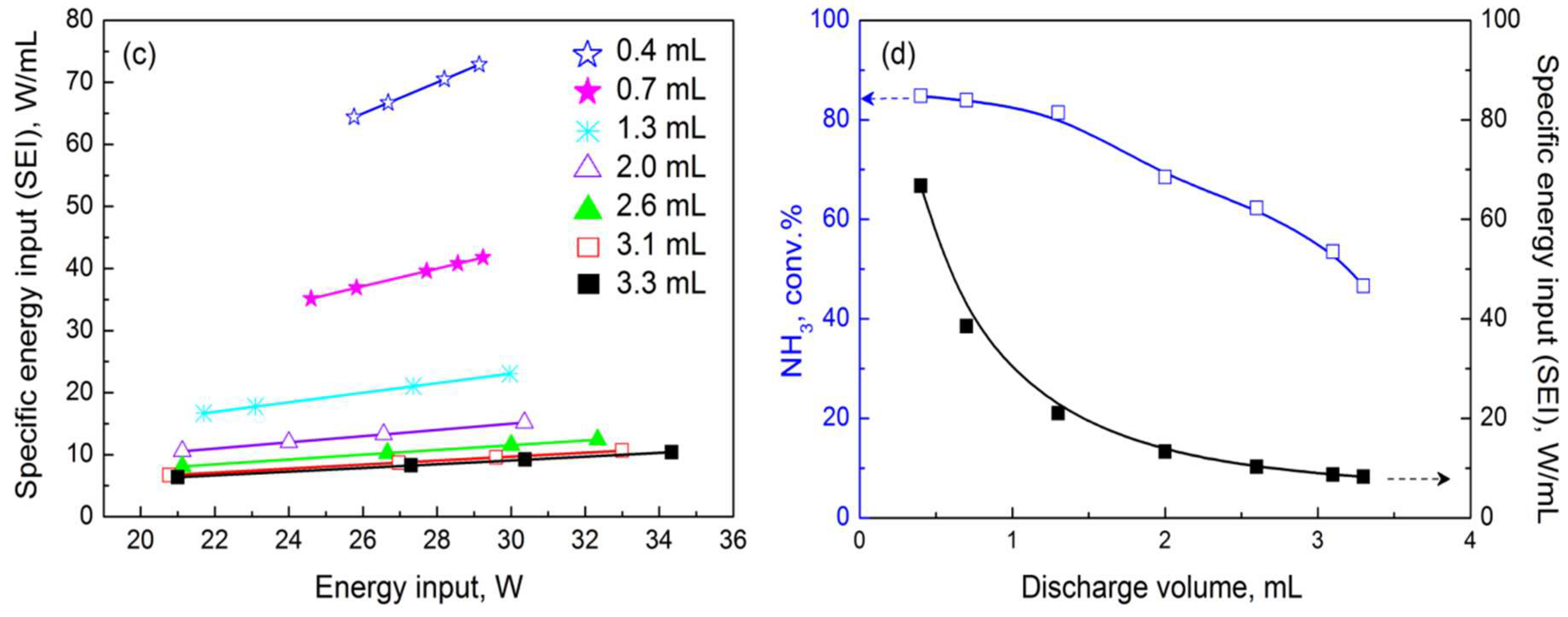
In Figure 6a, interestingly, the conversion of ammonia was greatly enhanced with discharge volume decrease, and partly packing catalyst into the discharge area was found to be better than that of full-packing mode. Among the cases studied, the discharge volume with 0.4 mL showed the best activity towards NH3 decomposition, in this case, the reaction temperature with 98.0% NH3 conversion was only 380 °C, which was 140 °C lower than that in the case of catalyst alone. At the reaction temperature of 380 °C, the conversion of NH3 over Co/fumed SiO2 is only 6.2% without plasma whereas, at the same conditions, the use of DBD plasma significantly enhanced the reaction performance, and the conversion of NH3 increased by a factor of 16 (from 6.1% to 98.0%) with decreasing discharge volume from 3.3 to 0.4 mL. Correspondingly, the energy efficiency of H2 formation increased from 11.9 to 15.9 mol(kW·h)−1; this is the highest H2 formation rate obtained in ammonia decomposition so far, as shown in Figure 6b. In addition, Figure 6c displayed that the specific energy input (SEI) significantly increased with decreasing discharge volume, which might be the reason for the high performance shown in Figure 6a,b. To exclude the effect of heat caused by SEI increasing on the reaction performance, the reaction temperatures with different discharge volumes were all controlled at around 350 °C by adjusting energy input, then the relationship of ammonia conversion and SEI was presented in Figure 6d. Clearly, the conversion of ammonia increased with SEI increasing, demonstrating that the high performance resulting from high SEI was not due to heating of the catalyst. Furthermore, our previous studies revealed that increasing energy input of discharge can significantly facilitate the desorption of the strong-adsorbed N from catalyst surface (rate-limiting step in ammonia decomposition) [11], thus, the nature of the contribution of high SEI was to accelerate the rate-limiting step of ammonia decomposition.
3. Materials and Methods
3.1. DBD Plasma-Catalytic Reactor
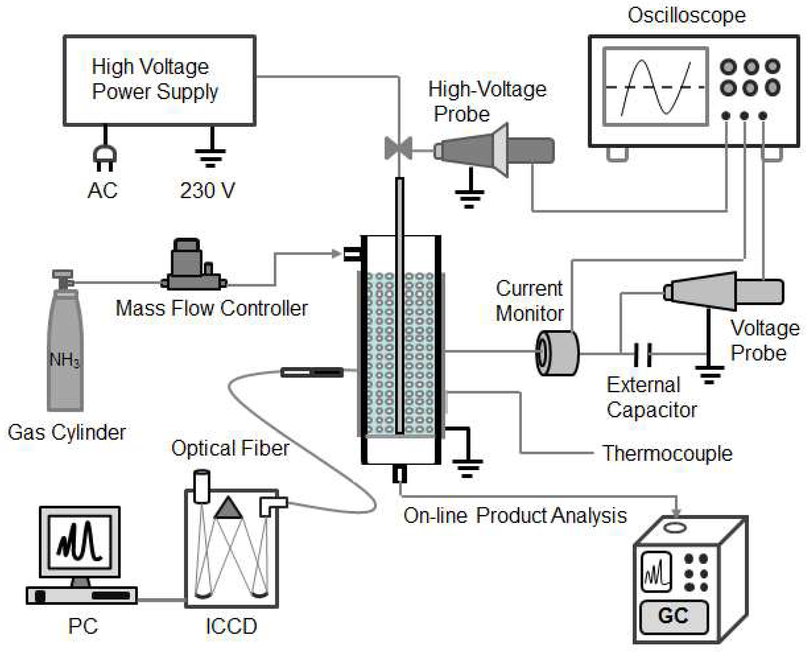
NH3 decomposition for H2 generation was carried out in a DBD reactor with a catalyst bed in the discharge area at atmospheric pressure (Scheme 2). The DBD reactor was a typical cylindrical reactor using a stainless-steel rod (2 mm o.d.) as a high-voltage electrode placed along the axis of a quartz tube (10 mm o.d. × 8 mm i.d.) which was used as a discharge dielectric. An aluminum foil sheet tightly covered the outside of the quartz cylinder and served as a ground electrode. A 3 mm of discharge gap was used, and catalyst was fully packed in the discharge area unless otherwise noted. The DBD reactor was connected to an AC high voltage power supply with a peak voltage of up to 30 kV and a variable frequency of 5–20 kHz. In this study, the discharge frequency was fixed at 12 kHz, and NH3 with a purity of 99.999% was fed into the DBD reactor at a total flow rate of 40 ml/min. The products of NH3 decomposition were analyzed on-line using a gas chromatograph (Shimadzu GC-2014) equipped with a thermal conductivity detector (TCD). The input power driving the reaction was determined from the product of the apparent voltage and current of AC power supply, and the discharge power was measured using a four-channel digital oscilloscope (Tektronix DPO 3012, high-voltage probe Tektronix P6015A, Tektronix Tech. Corp., Beaverton, OR, USA, current probe Pearson 6585, Pearson Electronics, Inc., San Jose, CA, USA).
To evaluate the reaction performance of plasma-catalytic NH3 decomposition to produce H2, the conversion of NH3 was calculated using Equation (1). The energy efficiency of H2 formation (mol(kW∙h)−1), defined as the number of moles of H2 produced per kilowatt hour, was calculated using Equation (2). The specific energy input (SEI), defined as the energy input per discharge volume, was calculated using Equation (3).
- : Energy efficiency of H2 formation, mol(kW∙h)−1
- : Conversion of NH3 , %
- : NH3 flow rate,
- P: Plasma power, kW
3.2. Catalyst Preparation
Cobalt nitrate was provided by the Tianjin Kermel Chemical Reagent Co., Ltd (Tianjin, China). Fumed SiO2 was purchased from the Dalian Luming Nanometer Material Co., Ltd (Dalian, China). Catalysts were synthesized either using the conventional preparation method and improved preparation method. Incipient wetness impregnation was used in this study. Briefly, cobalt nitrate (the theoretical metal loading was 30 wt %) was dissolved in deionized water. The support of fumed SiO2 was calcined, in advance, at 400 °C for 5 h to remove impurities, such as H2O, before impregnation, and then the pretreated support was added to the cobalt nitrate solution and stirred until it was thoroughly mixed. For “conventional preparation method”, the resulting mixture was kept at room temperature for 3 h and dried in air overnight at 110 °C. The dried sample was finally calcined in air at 540 °C for 5 h. Different from the conventional preparation method, for the “improved preparation method”, the resulting mixture was kept at room temperature for 3 h, followed by vacuum-freeze drying overnight at −50 °C before dried in air at 120 °C for 5 h, then the dried sample was calcined in a He-DBD plasma environment at 400 °C for 3 h to obtain the as-prepared catalyst. In addition, all the as-prepared catalysts were treated in NH3-DBD plasma at 400 °C for 0.3–1.0 h to reduce catalysts before evaluating their activity in NH3 decomposition.
3.3. Catalyst Characterization
X-ray diffraction (XRD) patterns of as-prepared catalysts were recorded using a Rigaku D-Max 2400 X ray diffractometer with Cu Kα radiation. Transmission electron microcopy (TEM) was used to characterize metal particles formed on the support surface (FEI Tecnai G2 F30 microscope, point resolution 0.2 nm, operated at 300 kV, Utrecht, Netherlands).
The reduction behavior of as-prepared catalyst was evaluated by H2 temperature-programmed reduction (H2-TPR) using a Chemisorption instrument (ChemBET 3000, Quantachrome, Boynton Beach, FL, USA). The sample (100 mg) was pretreated at 500 °C for 1 h under He flow (20 mL/min), and then cooled to 50 °C. The pretreated sample was exposed to a H2/He mixture (10 vol% H2) and was heated from 150 to 800 °C at a constant heating rate of 14 °C/min to get a H2-TPR profile. The acid–base properties of the as-prepared catalyst were tested by NH3 temperature-programmed desorption (NH3-TPD) using the same Chemisorption instrument with operating H2-TPR. The sample (140 mg) was pretreated at 500 °C for 1 h under He flow (20 mL∙min−1), and then cooled to 150 °C. The pretreated sample was saturated with NH3 for 30 min, and then purged with He flow for 1 h at 150 °C. The TPD profile was recorded while the sample was heated from 150 to 600 °C at a constant heating rate of 14 °C∙min−1 under He flow.
The specific surface area (Sg) of fumed SiO2 support was tested by N2 physisorption at −196 °C (Micrometrics ASAP 2020, Norcross, GA, USA). Prior to the N2 physisorption measurement, fumed SiO2 was degassed at 350 °C for 3 h, and Sg was calculated using the Brunauer−Emmett−Teller (BET) equation.
The metal loading of fumed SiO2 supported catalyst with different preparation methods was determined using X-ray fluorescence (XRF, SRS-3400, Bruker, Germany).
4. Conclusions
COx-free H2 generation from plasma-catalytic NH3 decomposition has been significantly promoted over Co/fumed SiO2 catalyst prepared with an improved preparation method, which featured the use of vacuum-freeze drying and DBD plasma calcination techniques during catalyst preparation. Compared with the activity of the catalyst prepared by the conventional preparation method, the conversion of NH3 increased by 47% on Co/fumed SiO2 catalyst prepared by improved method and, correspondingly, the energy efficiency of H2 production increased from 2.3 to 5.7 mol(kW·h)−1. The enhanced activity was mainly attributed to the high dispersion of Co particles on fumed SiO2 with a narrow particle size distribution (2–3 nm), which brought more active sites, stronger acidity, and a strong metal–support interaction. In addition, the reaction performance was significantly improved with the increase of specific energy input. At 380 °C, the highest energy efficiency of H2 formation achieved, so far, was 15.9 mol(kW·h)−1 over improved prepared Co/fumed SiO2 catalyst with 98.0% ammonia conversion at the optimal conditions.
Supplementary Materials
The following are available online at https://www.mdpi.com/2073-4344/9/2/107/s1. Figure S1. Peak analysis of H2-TPR profile obtained over Co3O4/fumed SiO2 catalyst; Table S1. XRF analysis of Co/fumed SiO2 with improved preparation method; Table S2. XRF analysis of Co/fumed SiO2 with conventional preparation method.
Author Contributions
Conceptualization, L.W., Y.Y. and H.G.; methodology, L.W. and Y.Y.; validation, L.W., Y.Y. and X.D.; formal analysis, L.W., Y.Y. and B.Z.; investigation, L.W. and Y.Y.; resources, H.C.G and Y.Z.; data curation, L.W. and Y.Y.; writing—original draft preparation, L.W.; writing—review and editing, L.W., Y.Y., B.Z. and Y.Z.; visualization, L.W., Y.Y. and X.D.; supervision, L.W., H.G. and Y.Z.; project administration, L.W., Y.Z. and H.G.; funding acquisition, L.W. and H.G.
Funding
This research was funded by the National Natural Science Foundation of China [20473016 and 20673018], the Liaoning Provincial Natural Science Fund of China [2018011143-301], and the Fundamental Research Funds for the Central Universities of China [DMU20110218002].
Conflicts of Interest
The authors declare no conflict of interest.
References
- Schüth, F.; Palkovits, R.; Schlögl, R.; Su, D.S. NH3 as a possible element in an energy infrastructure: Catalysts for NH3 decomposition. Energy Environ. Sci. 2012, 5, 6278–6289. [Google Scholar] [CrossRef]
- Lan, R.; Irvine, J.T.S.; Tao, S.W. NH3 and related chemicals as potential indirect H2 storage materials. Int. J. Hydrogen Energy 2012, 37, 1482–1494. [Google Scholar] [CrossRef]
- García-Bordejé, E.; Armenise, S.; Roldán, L. Toward practical application of H2 generation from NH3 decomposition guided by rational catalyst design. Catal. Rev. 2014, 56, 220–237. [Google Scholar] [CrossRef]
- Karim, A.M.; Prasad, V.; Mpourmpakis, G.; Lonergan, W.W.; Frenkel, A.I.; Chen, J.G.; Vlachos, D.G. Correlating particle size and shape of supported Ru/γ-Al2O3 Catalysts with NH3 Decomposition Activity. J. Am. Chem. Soc. 2009, 131, 12230–12239. [Google Scholar] [CrossRef] [PubMed]
- Yin, S.F.; Xu, B.Q.; Wang, S.J.; Ng, C.F.; Au, C.T. Magnesia-carbon nanotubes (MgO-CNTs) nanocomposite: Novel support of Ru catalyst for the generation of COx-free hydrogen from ammonia. Catal. Lett. 2004, 96, 113–116. [Google Scholar] [CrossRef]
- Marco, Y.; Roldán, L.; Armenise, S.; García-Bordejé, E. Support-induced oxidation state of catalytic Ru nanoparticles on carbon nanofibers that were doped with heteroatoms (O, N) for the decomposition of NH3. ChemCatChem 2013, 5, 3829–3834. [Google Scholar] [CrossRef]
- Zheng, W.Q.; Zhang, J.; Ge, Q.J.; Xu, H.Y.; Li, W.Z. Effects of CeO2 addition on Ni/Al2O3 catalysts for the reaction of NH3 decomposition to H2. Appl. Catal. B Environ. 2008, 80, 98–105. [Google Scholar] [CrossRef]
- Donald, J.; Xu, C.B.; Hashimoto, H.; Byambajav, E.; Ohtsuka, Y. Novel carbon-based Ni/Fe catalysts derived from peat for hot gas NH3 decomposition in an inert helium atmosphere. Appl. Catal. A Gen. 2010, 375, 124–133. [Google Scholar] [CrossRef]
- Hansgen, D.A.; Vlachos, D.G.; Chen, J.G. Using first principles to predict bimetallic catalysts for the NH3 decomposition reaction. Nat. Chem. 2010, 2, 484–489. [Google Scholar] [CrossRef]
- Lu, A.H.; Nitz, J.J.; Comotti, M.; Weidenthaler, C.; Schlichte, K.; Lehmann, C.W.; Terasaki, O.; Schüth, F. Experimental and theoretical investigation of molybdenum carbide and nitride as catalysts for NH3 decomposition. J. Am. Chem. Soc. 2010, 132, 14152–14162. [Google Scholar] [CrossRef]
- Wang, L.; Zhao, Y.; Liu, C.Y.; Gong, W.M.; Guo, H.C. Plasma driven NH3 decomposition on a Fe-catalyst: Eliminating surface nitrogen poisoning. Chem. Commun. 2013, 49, 3787–3789. [Google Scholar] [CrossRef] [PubMed]
- Wang, L.; Yi, Y.H.; Zhao, Y.; Zhang, R.; Zhang, J.L.; Guo, H.C. NH3 decomposition for H2 generation: Effects of cheap metals and supports on plasma−catalyst synergy. ACS Catal. 2015, 5, 4167–4174. [Google Scholar] [CrossRef]
- Wang, L.; Yi, Y.H.; Guo, Y.J.; Zhao, Y.; Zhang, J.L.; Guo, H.C. Synergy of DBD plasma and Fe-based catalyst in NH3 decomposition: Plasma enhancing adsorption step. Plasma Process Polym. 2017, 14, e1600111. [Google Scholar] [CrossRef]
- Yi, Y.H.; Wang, L.; Guo, Y.J.; Sun, S.Q.; Guo, H.C. Plasma-assisted ammonia decomposition over Fe-Ni alloy catalysts for COx-free hydrogen. AIChE J. 2019, 65, 691–701. [Google Scholar]
- Munnik, P.; de Jongh, P.E.; de Jong, K.P. Recent developments in the synthesis of supported catalysts. Chem. Rev. 2015, 115, 6687–6718. [Google Scholar] [CrossRef] [PubMed]
- Muñoz-Flores, B.M.; Kharisov, B.I.; Jiménez-Pérez, V.M.; Martínez, P.E.; López, S.T. Recent advances in the synthesis and main applications of metallic nanoalloys. Ind. Eng. Chem. Res. 2011, 50, 7705–7721. [Google Scholar] [CrossRef]
- Zaera, F. Nanostructured materials for applications in heterogeneous catalysis. Chem. Soc. Rev. 2013, 42, 2746–2762. [Google Scholar] [CrossRef]
- Kogelschatz, U. Dielectric-barrier discharges: Their history, discharge physics, and industrial applications. Plasma Chem. Plasma Process 2003, 23, 1–45. [Google Scholar] [CrossRef]
- Wang, L.; Yi, Y.H.; Guo, H.C.; Tu, X. Atmospheric pressure and room temperature synthesis of methanol through plasma-catalytic hydrogenation of CO2. ACS Catal. 2018, 8, 90–100. [Google Scholar] [CrossRef]
- Kameshima, S.; Tamura, K.; Ishibashi, Y.; Nozaki, T. Pulsed dry methane reforming in plasma-enhanced catalytic reaction. Catal. Today 2015, 256, 67–75. [Google Scholar] [CrossRef]
- Wang, L.; Yi, Y.H.; Wu, C.F.; Guo, H.C.; Tu, X. One-step reforming of CO2 and CH4 into high-value liquid chemicals and fuels at room temperature by plasma-driven catalysis. Angew. Chem. Int. Ed. 2017, 56, 13679–13683. [Google Scholar] [CrossRef] [PubMed]
- Snoeckx, R.; Heijkers, S.; Wesenbeeck, K.V.; Lenaerts, S.; Bogaerts, A. CO2 conversion in a dielectric barrier discharge plasma: N2 in the mix as a helping hand or problematic impurity. Energy Environ. Sci. 2016, 9, 999–1011. [Google Scholar] [CrossRef]
- Gao, Y.; Zhang, S.; Sun, H.; Wang, R.; Tu, X.; Shao, T. Highly efficient conversion of methane using microsecond and nanosecond pulsed spark discharges. Appl. Energy 2018, 226, 534–545. [Google Scholar] [CrossRef]
- Guo, Z.F.; Yi, Y.H.; Wang, L.; Yan, J.H.; Guo, H.C. Pt/TS-1 catalyst promoted C-N coupling reaction in CH4-NH3 plasma for HCN synthesis at low temperature. ACS Catal. 2018, 8, 10219–10224. [Google Scholar] [CrossRef]
- Liu, C.J.; Vissokov, G.P.; Jang, B. Catalyst preparation using plasma technologies. Catal. Today 2002, 72, 173–184. [Google Scholar] [CrossRef]
- Zhang, H.; Chu, W.; Xu, H.Y.; Zhou, J. Plasma-assisted preparation of Fe–Cu bimetal catalyst for higher alcohols synthesis from carbon monoxide hydrogenation. Fuel 2010, 89, 3127–3131. [Google Scholar] [CrossRef]
- Cheng, D.G. Plasma decomposition and reduction in supported metal catalyst preparation. Catal. Surv. Asia 2008, 12, 145–151. [Google Scholar] [CrossRef]
- Hinokuma, S.; Misumi, S.; Yoshida, H.; Machida, M. Nanoparticle catalyst preparation using pulsed arc plasma deposition. Catal. Sci. Technol. 2015, 5, 4249–4257. [Google Scholar] [CrossRef]
- Di, L.B.; Zhang, J.S.; Zhang, X.L. A review on the recent progress, challenges, and perspectives of atmospheric-pressure cold plasma for preparation of supported metal catalysts. Plasma Process Polym. 2018, 15, e1700234. [Google Scholar] [CrossRef]
- Wang, Z.; Zhang, Y.; Neyts, E.C.; Cao, X.X.; Zhang, X.S.; Jang, B.; Liu, C.J. Catalyst Preparation with Plasmas: How Does It Work? ACS Catal. 2018, 8, 2093–2110. [Google Scholar] [CrossRef]
- Wang, N.; Shen, K.; Yu, X.P.; Qian, W.Z.; Chu, W. Preparation and characterization of a plasma treated NiMgSBA-15 catalyst for methane reforming with CO2 to produce syngas. Catal. Sci. Technol. 2013, 3, 2278–2287. [Google Scholar] [CrossRef]
- Yan, X.L.; Zhao, B.R.; Liu, Y.; Li, Y.A. Dielectric barrier discharge plasma for preparation of Ni-based catalysts with enhanced coke resistance: Current status and perspective. Catal. Today 2015, 256, 29–40. [Google Scholar] [CrossRef]
- Guo, Z.L.; Huang, Q.S.; Luo, S.Z.; Chu, W. Atmospheric discharge plasma enhanced preparation of Pd/TiO2 catalysts for acetylene selective hydrogenation. Top. Catal. 2017, 60, 1009–1015. [Google Scholar] [CrossRef]
- Li, Y.A.; Jang, B. Selective hydrogenation of acetylene over Pd/Al2O3 catalysts: Effect of non-thermal RF plasma preparation methodologies. Top. Catal. 2017, 60, 997–1008. [Google Scholar] [CrossRef]
- Liu, Y.; Wang, Z.; Liu, C.J. Mechanism of template removal for the synthesis of molecular sieves using dielectric barrier discharge. Catal. Today 2015, 256, 137–141. [Google Scholar] [CrossRef]
- Zhang, Y.R.; Laerb, K.V.; Neyts, E.C.; Bogaerts, A. Can plasma be formed in catalyst pores? A modeling investigation. Appl. Catal. B Environ. 2016, 185, 56–67. [Google Scholar] [CrossRef]
- Wang, Z.; Wang, W.Z.; Zhang, L.; Jiang, D. Surface oxygen vacancies on Co3O4 mediated catalytic formaldehyde oxidation at room temperature. Catal. Sci. Technol. 2016, 6, 3845–3853. [Google Scholar] [CrossRef]
- Wang, Q.; Peng, Y.; Fu, J.; Kyzasd, G.Z.; Reduwan Billah, S.M.; An, S.Q. Synthesis, characterization, and catalytic evaluation of Co3O4/γ-Al2O3 as methane combustion catalysts: Significance of Co species and the redox cycle. Appl. Catal. B Environ. 2015, 168–169, 42–50. [Google Scholar] [CrossRef]
- Qazi, S.J.S.; Rennie, A.R.; Cockcroft, J.K.; Vickers, M. Use of wide-angle X-ray diffraction to measure shape and size of dispersed colloidal particles. J. Colloid Interf. Sci. 2009, 338, 105–110. [Google Scholar] [CrossRef]
- Luo, J.Y.; Meng, M.; Li, X.; Li, X.G.; Zha, Y.Q.; Hu, T.D.; Xie, Y.N.; Zhang, J. Mesoporous Co3O4–CeO2 and Pd/Co3O4–CeO2 catalysts: Synthesis, characterization and mechanistic study of their catalytic properties for low-temperature CO oxidation. J. Catal. 2008, 254, 310–324. [Google Scholar] [CrossRef]
- Teng, F.; Chen, M.D.; Li, G.Q.; Teng, Y.; Xu, T.G.; Hang, Y.C.; Yao, W.Q.; Santhanagopalan, S.; Meng, D.D.; Zhu, Y.F. High combustion activity of CH4 and catalluminescence properties of CO oxidation over porous Co3O4 nanorods. Appl. Catal. B Environ. 2011, 110, 133–140. [Google Scholar] [CrossRef]
- Vakros, J.; Kordulis, C.; Lycourghiotis, A. Cobalt oxide supported γ-Alumina catalyst with very high active surface area prepared by equilibrium deposition filtration. Langmuir 2002, 18, 417–422. [Google Scholar] [CrossRef]
- Arnoldy, P.; Moulijn, J.A. Temperature-programmed reduction of CoO/Al2O3 catalysts. J. Catal. 1985, 93, 38–54. [Google Scholar] [CrossRef]
- Hong, J.P.; Du, J.; Wang, B.; Zhang, Y.H.; Liu, C.C.; Xiong, H.F.; Sun, F.L.; Chen, S.F.; Li, J.L. Plasma-assisted preparation of highly dispersed Co enhanced Fischer–Tropsch synthesis performance. ACS Catal. 2018, 8, 6177–6185. [Google Scholar] [CrossRef]
Figure 1.
XRD patterns of as-prepared Co/fumed SiO2 catalysts using different approaches (Co3O4, JCPDS file No: 43-1003): (a) pure fumed SiO2, (b) improved preparation method, and (c) conventional preparation method.
Figure 1.
XRD patterns of as-prepared Co/fumed SiO2 catalysts using different approaches (Co3O4, JCPDS file No: 43-1003): (a) pure fumed SiO2, (b) improved preparation method, and (c) conventional preparation method.

Figure 2.
TEM images of as-prepared Co/fumed SiO2 catalysts using different approaches: (a) and (b) conventional preparation method; (c) and (d) improved preparation method.
Figure 2.
TEM images of as-prepared Co/fumed SiO2 catalysts using different approaches: (a) and (b) conventional preparation method; (c) and (d) improved preparation method.

Figure 3.
NH3-TPD profiles of as-prepared Co/fumed SiO2 catalysts using different approaches.

Figure 4.
H2-TPR profiles of as-prepared Co/fumed SiO2 catalysts using different approaches.

Figure 5.
Plasma-catalytic NH3 decomposition over Co/fumed SiO2 catalyst with different preparation methods: (a) the conversion of NH3; (b) the energy efficiency of H2 generation (NH3 feed rate 40 mL/min−1, supported catalyst 0.88 g, discharge gap 3 mm, discharge frequency 12 kHz; The reaction temperature originated from electric heat released by discharge, and was determined using an IR camera and thermocouple tightly attached to the outer wall of the reactor [12]).

Scheme 1.
Scheme of combining mode of plasma and Co/fumed SiO2 catalyst (note: HV denotes high voltage; catalyst was fixed at about 3 g , but the discharge volume changes with the shortening of the length of the HV electrode, which results in the catalyst being partly packed in the field of plasma by changing the discharge volume “V” from 3.3 to 0.4 mL).

Figure 6.
Influence of discharge volume on (a) ammonia conversion, (b) energy efficiency of H2 formation, (c) specific energy input (SEI) and (d) relationship of ammonia conversion with SEI (NH3 feed rate 40 mL/min, discharge gap 3 mm, discharge frequency 12 kHz, and the packing amount and packing volume of catalyst in the reactor was fixed at about 3 g and 3.1 mL, respectively. Changing the discharge volume “V” from 3.3 to 0.4 mL enabled the catalyst to be partly packed in the discharge area, as shown in Scheme 1, and the catalyst was fully packed in the field of plasma only when the discharge volume was over 3.1 mL; The reaction temperature originated from electric heat released by discharge, and was determined using an IR camera and thermocouple tightly attached to the outer wall of the reactor [12]).


Scheme 2.
Schematic diagram of experimental setup.

© 2019 by the authors. Licensee MDPI, Basel, Switzerland. This article is an open access article distributed under the terms and conditions of the Creative Commons Attribution (CC BY) license (http://creativecommons.org/licenses/by/4.0/).
Share and Cite
MDPI and ACS Style
Wang, L.; Yi, Y.; Guo, H.; Du, X.; Zhu, B.; Zhu, Y. Highly Dispersed Co Nanoparticles Prepared by an Improved Method for Plasma-Driven NH3 Decomposition to Produce H2. Catalysts 2019, 9, 107. https://doi.org/10.3390/catal9020107
AMA Style
Wang L, Yi Y, Guo H, Du X, Zhu B, Zhu Y. Highly Dispersed Co Nanoparticles Prepared by an Improved Method for Plasma-Driven NH3 Decomposition to Produce H2. Catalysts. 2019; 9(2):107. https://doi.org/10.3390/catal9020107
Chicago/Turabian StyleWang, Li, YanHui Yi, HongChen Guo, XiaoMin Du, Bin Zhu, and YiMin Zhu. 2019. "Highly Dispersed Co Nanoparticles Prepared by an Improved Method for Plasma-Driven NH3 Decomposition to Produce H2" Catalysts 9, no. 2: 107. https://doi.org/10.3390/catal9020107
Note that from the first issue of 2016, this journal uses article numbers instead of page numbers. See further details here.