Article

Fabrication and Electrochemical Performance of Zn-Doped La0.2Sr0.25Ca0.45TiO3 Infiltrated with Nickel-CGO, Iron, and Cobalt as an Alternative Anode Material for Solid Oxide Fuel Cells

by
Nazan Muzaffar
1,2,
Nasima Arshad
2,
Daniel Bøgh Drasbæk
1,
Bhaskar Reddy Sudireddy
1 and
Peter Holtappels
1,*
1
Technical University of Denmark, Department of Energy Conversion and Storage Frederiksborgvej 399, 4000 Roskilde, Denmark
2
Department of Chemistry, Allama Iqbal Open University, Islamabad 44000, Pakistan
*
Author to whom correspondence should be addressed.
Catalysts 2019, 9(3), 269; https://doi.org/10.3390/catal9030269
Submission received: 25 December 2018 / Revised: 7 March 2019 / Accepted: 9 March 2019 / Published: 16 March 2019
(This article belongs to the Special Issue Solid Oxide Fuel Cells – The Low Temperature Challenge)

Abstract

:
In solid oxide fuel cells, doped strontium titinates have been widely studied as anode materials due to their high n-type conductivity. They are used as current conducting backbones as an alternative to nickel-cermets, which suffer degradation due to coking, sulphur poisoning, and low tolerance to redox cycling. In this work, anode backbone materials were synthesized from La0.2Sr0.25Ca0.45TiO3−δ (LSCTA-), modified with 5 wt.% Zn, and infiltrated with nickel (Ni)/ceria gadolinium-doped cerium oxide (CGO), Fe, and Co. The electrodes were further studied for their electrochemical performance using electrochemical impedance spectroscopy (EIS) at open circuit voltage (OCV) in different hydrogen to steam ratios and at various operating temperatures (850–650 °C). Infiltration of electrocatalysts significantly reduced the polarization resistance and among the studied infiltrates, at all operating temperatures, Ni-CGO showed excellent electrode performance. The polarization resistances in 3% and 50% H2O/H2 atmosphere were found to be 0.072 and 0.025 Ω cm2, respectively, at 850 °C, and 0.091 and 0.076 Ω cm2, respectively, at 750 °C, with Ni-CGO. These values are approximately three orders of magnitude smaller than the polarization resistance (25 Ω cm2) of back bone material measured at 750 °C.

1. Introduction

Solid oxide fuel cells (SOFC) to date have used mostly Ni/8 mole% yttria-stabilized zirconia (YSZ) cermet as an anode material. These anodes have shown high catalytic activity and stability at operating temperatures of 700 to 950 °C and under reducing atmospheres. However, Ni-YSZ cermet anodes suffer some drawbacks, such as degradation from coking by carbon, oxidation of nickel particles, and sulfur poisoning [1,2,3,4,5,6]. Several research groups around the world are working continuously to develop alternative anode materials to overcome the problems arising from Ni-YSZ cermet anodes. Among various materials, ceramic perovskites are frequently explored as an alternative to Ni [7,8]. The general formula of these perovskites is ABX3, where A and B are cations of different sizes and X is the anion. The perovskite structure is robust and allows for multiple chemical modifications to tailor its chemical and physical properties.
Among ceramic perovskites, rare-earth-doped SrTiO3 is considered the most suitable anode candidate for fuel cells [9], particularly when doped with lanthanum, as its ionic size is similar to that of strontium [10]. Ti4+ is reduced to Ti3+ under reducing conditions by the introduction of a trivalent lanthanum ion to the divalent Sr A-site, resulting in n-type conductivity under an H2 type atmosphere [11]. In addition to this, lanthanum titanate has chemical and dimensional stability upon redox cycling, coking resistance, and a high sulfur tolerance [12,13,14,15]. However, its low electrocatalytic activity with respect to hydrogen oxidation reactions has made its performance poor in comparison with the Ni/YSZ anode [10,16,17]. Therefore, it is necessary to improve catalytic activity, which can be done either by infiltration or ex-solution of catalytic active materials [18,19,20]. This was applied initially to ceria-based SOFC anodes [21] but is now a general strategy used to improve the electro catalytic properties of ceramic electrodes.
Ramos et al. infiltrated porous Sr0.94Ti0.9Nb0.1O3 (STN94) backbones with metal nanoparticles (Ni, Pd, and Ru) and gadolinium-doped cerium oxide (CGO). This infiltration resulted in an increase in the performance and stability of the SOFC anode compared to conventional Ni/YSZ anodes [22,23]. It was reported that polarization resistances in 50% H2O/H2 at 850 °C were 0.02 Ω cm2, 0.04 Ω cm2, and 0.1 Ω cm2 for the Ru-CGO, Pd-CGO, and Ni-CGO infiltrations, respectively [21]. However, rare earth metals like ruthenium and palladium, while stable and good anode catalysts, are not suitable for commercial use due to their high costs. Other metals like Ni, Co, Mo, Fe, W, and Cu have previously been studied in either cermet electrodes or on electrically-conducting ceramics to decrease carbon coking in the cell [24] while it has been found that molybdenum might obstruct sulfur poisoning [25].
Lanthanum strontium calcium titanate, La0.2Sr0.25Ca0.45TiO3−δ (LSCTA-), is a relatively new backbone material in which SrTiO3 is co-doped with La and Ca on the perovskite A-site; it has been reported for its anode performance [26]. Further B-site doping of some transition metals for LSCTA- [27] has also been reported to improve its electrical properties. Zn as a two-valent cation with similar radii to the B-site cation Ti3+ in both four- and six-fold coordination is an interesting substitute for Ti3+ which could improve stability by favoring Ti in the +4 oxidation state. Thus, an attempt was made to develop an anode material by partially substituting Ti with Zn as a dopant at the B-site of LSCTA-. The resulting backbone, La0.2Sr0.25Ca0.45Ti0.95Zn0.05O3−δ (LSCTZ5), was investigated in this work for its electrochemical performance before and after infiltration with Fe, Co, and Ni-CGO under a reducing atmosphere and at different operating temperatures. No such studies with Zn-doped LSCTA- have yet been reported.

2. Results and Discussion

2.1. X-ray Diffraction

The phase purity of the samples was investigated by X-ray diffraction (XRD). XRD patterns of doped analogues showed a characteristic reflection of the perovskite crystal structure, as seen in Figure 1. The XRD pattern matched with the parent composition of LSCTA-. Samples were pre-reduced at 850 °C for 1 h in 5% H2/Ar and XRD was recorded again to check the structural integrity of calcined and pre-reduced samples. LSCTZ5 retained its perovskite structure and no extra peaks were recorded. A slight contraction of the unit cell was noted which could not be explained by the normal reduction of the B-site cation but resulted from coordination changes around Zn from six to four due to oxygen vacancy formation.

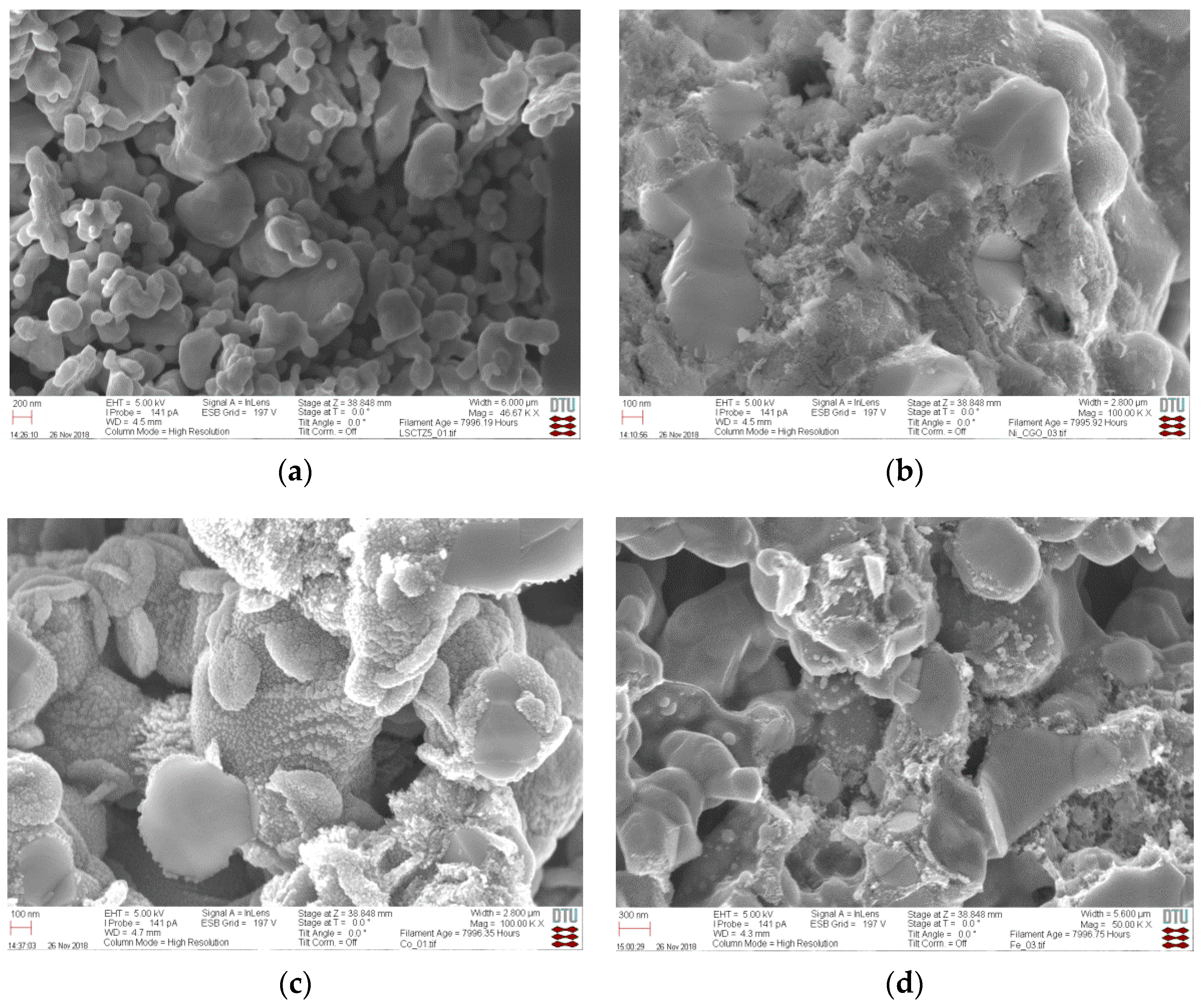
2.2. Microstructure of Infiltrated Cells

Microstructure analysis of the LSCTZ5 anode infiltrated with Ni, Fe, Co, and Ni-CGO before testing shows a porous backbone structure with particle sizes between 0.1 μm and 1 μm. A comparison of LSCTZ5 without and in the presence of infiltrated electrocatalysts before testing is given in Figure 2. Figure 2b–d indicates the presence of infiltrated material with nano-structured features after infiltration. The results indicate a rather homogeneous distribution of infiltrated nanoparticles on the porous backbone structure; hence, in our studies, infiltration worked effectively to prepare the composite structures.
The micrographs of infiltrated LSCTZ5 anode materials after testing at 850 °C, in which the presence of isolated sub-micronparticles can still be distinguished, are given in Figure 3. While Ni-CGO infiltration results in particles of up to 100 nm, larger particle sizes of up to a couple of 100 nm are indicated for Co and Fe infiltration.
The average weight gain of the samples after wet infiltration is given in Table 1. The weight gain is similar for the pure metal infiltrations, being slightly below 1 wt.%, while the Ni-CGO infiltrations are at around 4%. The mass increase confirms the introduction of catalytic material into the porous structure. Due to the higher molar weight of CGO compared to Ni, and the fact that the molar fraction of Ni is only 10% in Ni-CGO, the total metal Ni loading in Ni-CGO is approximately 3–4 times less than that in the pure metal infiltrated samples. This is in agreement with the microstructures in Figure 3, which show a reduced number of small particles for the Ni-CGO case compared to the Co and Fe infiltrated samples. Additionally, a slightly denser microstructure is indicated when comparing Figure 3a with Figure 3b, c that could result from the additional CGO material. The Ni-CGO ratio of 1:9 was found to be advantageous based on [22] and the total amount was chosen as a trade-off for having a comparable metal loading to the pure metal elements without introducing too much infiltrate into the sample that could compromise on open porosity.

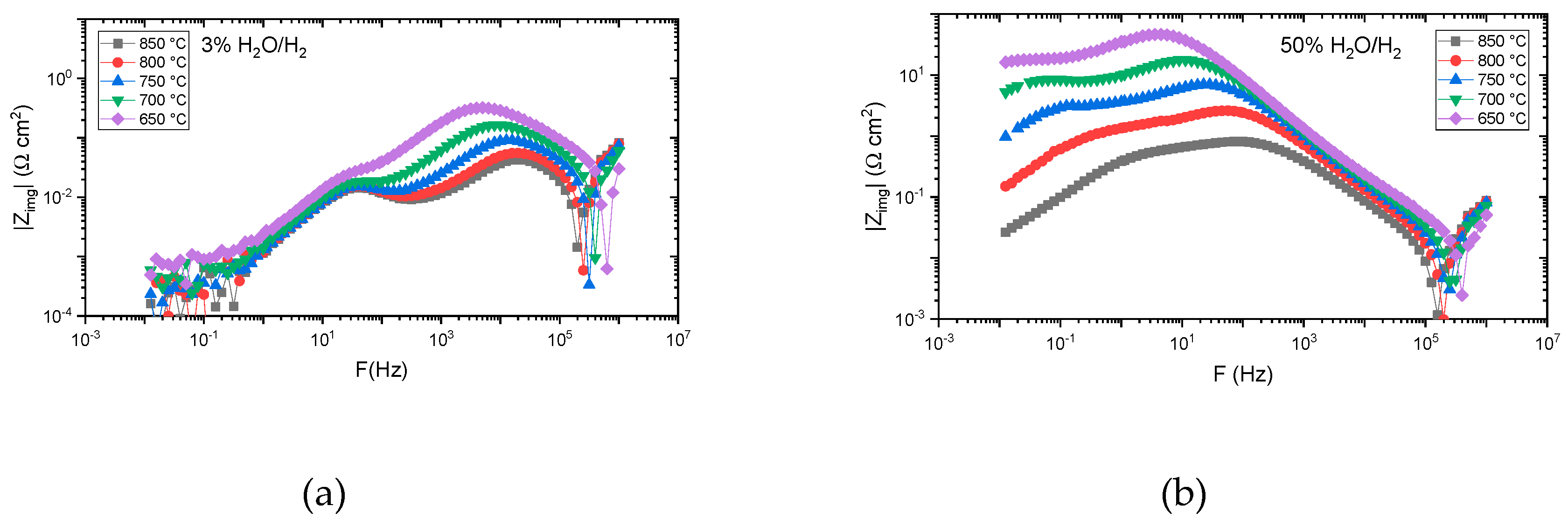
2.3. Electrochemical Characterization by Impedance Measurements of LSCTZ5 Infiltrated with Ni-CGO, Co, and Fe

The impedance spectra of infiltrated cells at different operating temperatures in 3% H2O/H2 and 50% H2O/H2 at 750 °C are shown in Figure 4 (those at other temperatures are provided in Figure S1 in the Supplementary Material). One dominating semicircle is observed for most of the samples, though with differences in the polarization resistance. The ohmic resistances compared with the pure backbone as well as among the infiltrated electrodes range from 0.3 to 0.4 Ω cm2 (at 750 °C). This indicates that infiltration does not affect the ohmic resistance (Rs)compared to the pure backbone. As the operating temperature is changed from 850 °C to 650 °C the Rs values (shown in Table 2) are enhanced, as with polarization resistance (Rp) (shown in Table 3).
The impedance spectra (Nyquist plots) of the infiltrated LSCTZ5 show that the infiltrated LSCTZ5 anode exhibits a lower polarization resistance compared to the LSCTZ5 backbone, as seen in Figure 4 and Table 3. This is consistent with other perovskite/ceramic electrodes. Although perovskite oxides like doped strontium titinates have high electrical conductivity, they possess low oxygen ion conductivity and poor catalytic activity for hydrogen oxidation [28,29]. A comparison of all the investigated infiltration measurements shows that at higher temperatures RP is low and with a decrease in temperature there is an increase in the RP value. The polarization resistance value from the impedance data of LSCTZ5 (without infiltration) shows a value of 25 Ω cm2 in 4% H2O/H2 at 750 °C, which is significantly reduced upon infiltration with all the infiltrated catalysts.
As regards the single metal infiltrations, Co infiltration is superior to Fe in a hydrogen atmosphere containing 50% steam, while in 3% steam the Fe infiltrations show a lower polarization resistance. The impedance indicated in Figure 4 shows a significant change frequency dispersion that suggests a change in the electrode processes when exposing the Fe infiltrated sample to 50% steam, something which is not indicated for the Co and Ni-CGO infiltrations.
Compared to single electrocatalysts infiltration, co-infiltration of Ni with CGO further decreases the polarization resistance significantly despite the lower metal loading in this case. As is also obvious from the data (in Table 3 and Figure S1 in the Supplementary Material), at a temperature of 850 °C, the polarization resistance of the Ni-CGO-infiltrated LSCTZ5 is 0.072 Ω cm2 in 3% H2O/H2 and 0.025 Ω cm2 in 50% H2O/H2. These values are lower when compared with those in the reported literature for Ni-CGO-infiltrated STN94 (0.1 Ω cm2) [22] and Ni-CGO-infiltrated LSCT (0.50 Ω cm2) [26]. The polarization resistances at 650 °C of 0.2 and 0.33 Ω cm2 in 3% and 50% H2O make LSCTZ5 infiltrated with Ni-CGO a very promising candidate for low temperature SOFCs. The excellent electrode performance of Ni-CGO-infiltrated LSCTZ5 anode may be explained by the existence of an extended reaction zone and triple phase boundaries within the porous electrode created as a result of the addition of ion-conducting CGO.
The bode plots in Figure 5 show the impedance-imaginary part as a function of temperature (only Fe infiltration is shown, with other infiltrations provided as Figure S2 in the Supplementary Material). For 3% water at high temperatures, the low frequency region indicates a temperature-independent process with an RP of around 0.05 cm2. This low-frequency process seems to vanish with higher water/oxygen content and is likely to be a gas phase effect which is only visible at a low percentage of water, at high temperature, and for active electrodes [22]. Increasing the water/oxygen content does not significantly affect the summit frequencies of the high-frequency process in the case of Ni-CGO- and Co-infiltration, while for Fe-infiltrated electrodes the summit frequency is moved by approximately two orders of magnitude to lower frequencies. This difference points to to a severe change in electrode or electrochemical processes on the Fe-infiltrated samples when increasing the water/hydrogen ratio to 1/1, which is not observed for Ni-CGO- and Co-infiltrated samples.

2.4. Temperature Dependence

To study temperature dependence, the data was analyzed using an Arrhenius plot as shown in Figure 6 for Ni-CGO-, Co- and Fe-infiltrated LSCTZ5. In this plot, the common logarithm of polarization resistance is plotted against the inverse of temperature; the activation energy was calculated from the slope of the curve by multiplying it with the gas constant as well as the Faraday constant, with the results given in Table 4 [30].
The Arrhenius plots for the Rp in 50% H2O/H2 are more linear compared to those for 3% H2O/H2, which show a tendency to lower activation energies at temperatures higher than 750 °C. This behavior is in agreement with the additional contribution of a temperature-independent impedance for the high performing Ni-CGO- and Fe-infiltrated cells with low water contents and high temperatures, indicating that temperature dependence is determined by at least two processes. Thus, the activation energy in 3% H2O/H2 was evaluated separately for a high and low temperature region in the Arrhenius plots, as given in Table 4. For the high temperature region, the corresponding values for Ni-CGO- and Fe-infiltrated samples can be attributed to the temperature independent low frequency process, while for the Co-infiltrated samples an overlaying degradation at 800 and 850 °C (see Figure S1) is the likely cause of the reduced temperature dependence. Thus, the values for the high temperature region cannot be attributed to a single process and are only considered apparent activation energies.
In the low temperature region, the activation energy depends on the infiltrated electrocatalyst and the gas atmosphere. The Ni-CGO samples had the lowest activation energy among all the samples in both the 3% and 50% water atmospheres. Increasing the water content resulted in an increase in the activation energy, which is very pronounced for Fe. With the use of Ellingham diagrams it could be concluded that among Ni, Co, and Fe, the oxygen partial pressure for reoxidation of the metal is lowest for Fe. Thus, a tentative explanation for the behavior of the Fe-infiltrated electrode is a partial reoxidation of the Fe electrocatalysts in a 50% water/hydrogen atmosphere.
Summarizing the results for individual performances and temperature dependence, low activation energy and low polarization resistance make the Ni-CGO-infiltrated LSCTZ5 electrode a promising candidate for anode material for solid oxide fuel cells at low operating temperatures.

3. Materials and Methods

3.1. Symmetrical Cell Fabrication

La0.2Sr0.25Ca0.45TiO3−δ (LSCTA-) modified with 5 wt.% Zn was synthesized by Pechini synthesis [11]. The slurry used for the preparation of the symmetrical cell was prepared by de-agglomerating the Zn-doped LSCT powders using rotatory ball milling in ethanol. The LSCTZ5 slurry was spray-coated onto a pre-sintered 230–250 µm thick YSZ electrolyte and finally sintered at 1200 °C and 1250 °C for 8 h in air. The electrode thickness ranged from 20 to 40 µm. Detail of the synthesis of the symmetrical cells can be found in [31]. Using the wet infiltration procedure, a drop of infiltrate solution was placed on the surface of the cell for symmetrical LSCTZ5/YSZ infiltration. The capillary force helped in the equal distribution of the drop through the porous structure and down to the electrode-electrolyte interface. The drop was left for one minute on the cell surface and the residuals were wiped off. The process was repeated on the other side of the cell. The infiltration process was repeated three times with an intermediate calcination at 350 °C for 30 min; however, in the last repetition the calcination step was extended to two hours to ensure total calcination.

3.2. Microstructure Characterization

The microstructure of the cells was investigated from the broken cross-section, without any pretreatment of the samples, using a scanning electron microscope or HRSEM (Zeiss Merlin). The microstructure of the samples was investigated directly after infiltration and after electrochemical characterization.

3.3. Electrochemical Characterization

Pt paste was hand-painted on both sides of the infiltrated cells (0.6 × 0.6 cm2) for the current collection layer. A specially-designed rig which allows for four symmetrical cells per test was used to do electrochemical measurements [32]. The samples were characterized by electrochemical impedance spectroscopy in steps of 50 °C from 850 °C to 650 °C in 3% H2O/H2 and in 50% H2O/H2 at open circuit voltage. The protocol performed can be described as heating up to 850 °C in air, followed by a 30 min reduction of the cells in 3% H2O/H2. After the cell reduction, the first EIS measurements in 3% H2O/H2 were performed, followed by the impedance measurements every 50 °C down to 650 °C. The temperature was again raised to 850 °C and EIS measurements in 50% H2O/H2 were carried out, following the same procedure as for the 3% H2O/H2 atmosphere. The electrochemical impedance analysis was performed using a Gamry Reference 600 within 50 mV amplitude between 0.01–1 MHz. The impedance data were analyzed using Elchemea software [33].

4. Conclusions

In this work, nano-structured Zn doped La0.2Sr0.25Ca0.45TiO3−δ (LSCTA-), named LSCTZ5, was used as a backbone material for infiltration with Fe, Co, and Ni-CGO. All infiltrates were found to be dispersed homogeneously within the LSCTZ5 backbone structure and showed comparatively low polarization resistance compared to the LSCTZ5 backbone on its own. Among the infiltrates, Ni-CGO showed the best performance in terms of polarization resistance at open circuit voltage (OCV). The excellent electrode performance of Ni-CGO-infiltrated LSCTZ5 anode may be explained by the extended triple phase boundaries created as a result of the addition of ion-conducting CGO. Furthermore, Ni-CGO- and Co-infiltrations showed lower polarization resistance values in an 50% H2O/H2 atmosphere than in an 3% H2O/H2 atmosphere, while the opposite was the case for Fe. Compared to other Sr-titanates infiltrated with Ni-CGO, the performance of LSCTZ5 was surprisingly good, indicating that the electrode backbone affects the electrocatalyst performance. In general, all the infiltrated anode materials showed an excellent reduction in RP values and hence point towards promising alternatives to Ni-cermet electrodes for intermediate temperature SOFCs. Whether their superior performance can be attributed to the Ni-CGO combination or simply to the addition of a mixed conducting CGO phase to a 3D metal electrocatalyst should be subject to further investigation.

Supplementary Materials

The following are available online at https://www.mdpi.com/2073-4344/9/3/269/s1, Figure S1. Nyquist plots of Ni-CGO- (a,b), Co- (c,d), and Fe- (e,f) infiltrated LSCTZ5 at different operating temperatures in 3% H2O/H2 and 50% H2O/H2. Figure S2. Bode plots of Ni-CGO- (a,b), Co- (c,d), and Fe- (e,f) infiltrated LSCTZ5 at different operating temperatures in 3% H2O/H2 and 50% H2O/H2.

Author Contributions

This research was part of the PhD work of N.M. under the supervision of N.A. and P.H. The experimental work was carried out at the Department of Energy Conversion and Storage, DTU, by N.M. and D.B.D. under the supervision of P.H. N.M. wrote the manuscript with the help of D.B.D. and B.R.S. and was supervised by N.A. and P.H. Correspondence for the manuscript with the journal was done by P.H.

Funding

The author is thankful to the Higher Education Commission for providing the IRSIP scholarship. This work was also supported by the Horizon 2020 funded project Balance (grant number 731224).

Acknowledgments

Karl Tor SuneThydén is acknowledged for his help with SEM structural analysis.

Conflicts of Interest

The authors declare no conflict of interest.

References

  1. Jiang, S.P. Sintering behavior of Ni/Y2O3-ZrO2 cermet electrodes of solid oxide fuel cell. J. Mater. Sci. 2003, 38, 3775–3782. [Google Scholar] [CrossRef]
  2. Girona, K.; Laurencin, J.; Fouletier, J.; Lefebvre-Joud, F. Carbon deposition in CH4/CO2 operated SOFC: Simulation and experimentation studies. J. Power Sources 2012, 210, 381–391. [Google Scholar] [CrossRef]
  3. Kim, Y.J.; Lee, H.M.; Lim, H.T. Degradation comparison of hydrogen and internally reformed methane-fueled solid oxide fuel cells. J. Korean Ceram. Soc. 2016, 53, 483–488. [Google Scholar] [CrossRef]
  4. Chuang, K.T.; Luo, J.; Sanger, A. Evolution of fuel cells powered by H2S-containing gases. Chem. Ind. Chem. Eng. Q. 2008, 14, 69–76. [Google Scholar]
  5. Cheng, Z.; Wang, J.H.; Choi, Y.M.; Yang, L.; Lin, M.C.; Liu, M. From Ni-YSZ to sulfur tolerant anode materials for SOFCs: Electrochemical behavior, in situ characterization, modelling, and future perspectives. Energy Environ. Sci. 2011, 4, 4380–4409. [Google Scholar] [CrossRef]
  6. Lee, K.J.; Lee, M.J.; Park, S.H.; Hwang, H.J. Symmetrical solid oxide electrolyzed cells (SOECs) with La0.6 Sr0.4Co0.2Fe0.8O3 (LSCF)-Gadolinium doped ceria (GDC) composite electrodes. J. Korean Ceram. Soc. 2016, 53, 489–493. [Google Scholar] [CrossRef]
  7. Singh, K.; Nowotny, J.; Thangadurai, V. Amphoteric oxide semiconductors for energy conversion devices: A tutorial review. Chem. Soc. Rev. 2013, 42, 1961–1972. [Google Scholar] [CrossRef] [PubMed]
  8. Ishihara, T. Nanomaterials for advanced electrode of low-temperature solid oxide fuel cells (SOFCs). J. Korean Ceram. Soc. 2016, 53, 469–477. [Google Scholar] [CrossRef]
  9. Hui, S.; Petric, A. Electrical properties of yttrium-doped strontium titanate under reducing conditions. J. Electrochem. Soc. 2002, 149, J1–J10. [Google Scholar] [CrossRef]
  10. Zhou, X.; Yan, N.; Chuang, K.T.; Luo, J. Progress in La-doped SrTiO3 (LST)-based anode materials for solid oxide fuel cells. RSC Adv. 2014, 4, 118–131. [Google Scholar] [CrossRef]
  11. Savaniu, C.D.; Miller, D.N.; Irvine, J.T.S. Scale up and anode development for La- Doped SrTiO3 anode-supported SOFCs. J. Am. Ceram. Soc. 2013, 96, 1718–1723. [Google Scholar] [CrossRef]
  12. Ma, Q.; Tietz, F.; Leonide, A.; Ivers-Tiffee, E. Electrochemical performances of solid oxide fuel cells based on Y-substituted SrTiO3 ceramic anode materials. J. Power Sources 2011, 196, 7308–7312. [Google Scholar] [CrossRef]
  13. Marina, O.A.; Canfield, N.L.; Stevenson, J.W. Thermal, electrical, and electrocatalytical properties of lanthanum-doped strontium titanate. Solid State Ionics 2002, 149, 21–28. [Google Scholar] [CrossRef]
  14. Vincent, A.L.; Luo, J.L.; Chuang, K.T.; Sanger, A.R. Promotion of activation of CH4 by H2S in the oxidation of sour gas over sulfur tolerant SOFC anode catalysts. Appl. Catal. 2011, 106, 114–122. [Google Scholar] [CrossRef]
  15. Mukundan, R.; Brosha, E.L.; Garzon, F.H. Sulfur tolerant anodes for SOFCs. Electrochem. Solid State Lett. 2004, 7, A5–A7. [Google Scholar] [CrossRef]
  16. Mahato, N.; Banerjee, A.; Gupta, A.; Omar, S.; Balani, K. Progress in material selection for solid oxide fuel cell technology: A review. Prog. Mater. Sci. 2015, 72, 141–337. [Google Scholar] [CrossRef]
  17. Zhang, L.; Jing, S.P.; Wang, W.; Zhang, Y. NiO/YSZ, anode-supported, thin-electrolyte, solid oxide fuel cells fabricated by gel casting. J. Power Sources 2007, 170, 55–60. [Google Scholar] [CrossRef]
  18. Savaniu, C.D.; Irvine, J.T.S. La-doped SrTiO3 as anode materials for IT-SOFC. Solid State Ionics. 2011, 192, 491–493. [Google Scholar] [CrossRef]
  19. Yoo, K.B.; Choi, G.M. Performance of La-doped strontium titanite (LST) anode on LaGaO3-based SOFC. Solid State Ionics 2009, 180, 867–871. [Google Scholar] [CrossRef]
  20. Arrive, C.; Delahaye, T.; Joubert, O.; Gauthier, G. Exsolution of nickel nanoparticles at the surface of a conducting titanate as potential hydrogen electrode material for solid oxide electrochemical cells. J. Power Sources 2013, 223, 341–348. [Google Scholar] [CrossRef]
  21. Watanabe, M.; Uchida, H.; Shibata, M.; Mochizuki, N.; Amikura, K. High Performance Catalyzed-Reaction Layer for Medium Temperature Operating Solid Oxide Fuel Cells. J. Electrochem. Soc. 1994, 141, 342–346. [Google Scholar] [CrossRef]
  22. Ramos, T.; Veltze, S.; Sudireddy, B.R.; Holtappels, P. Impedance and stability of M/CGO (M: Ni, Pd, Ru) Co-infiltrated Nb-doped SrTiO3 SOFC anodes. Electrochem. Lett. 2014, 3, F5–F6. [Google Scholar] [CrossRef]
  23. Ramos, T.; Veltze, S.; Sudireddy, B.R.; Jørgensen, P.S.; Kuhn, L.T.; Holtappels, P. Effect of Ru/CGO versus Ni/CGO Co-infiltration on the performance and stability of STN–based SOFCS. Fuel Cells 2014, 14, 1062–1065. [Google Scholar] [CrossRef]
  24. Boldrin, P.; Ruiz-Trejo, E.; Mermelstein, J.; Menendez, J.M.; Reina, T.R.; Brandon, N.P. Strategies for carbon and sulphur tolerant solid oxide fuel cell materials, incorporating lessons from heterogeneous catalysis. Chem. Rev. 2016, 116, 13633–13684. [Google Scholar] [CrossRef] [PubMed]
  25. Gonzalez, M.G.; Pronzi, E.N.; Ferretti, O.A.; Quincoces, C.E.; Marecot, P.; Barbier, J. Studies of H2S adsorption and carbon deposition over Mo-Ni/Al2O3 catalysts. Adsorpt. Sci. Technol. 2000, 18, 515–527. [Google Scholar] [CrossRef]
  26. Verbraeken, M.C.; Iwanschitz, B.; Mai, A.; Irvine, J.T.S. Evaluation of calcium-doped La0.2Sr0.7TiO3 as an alternative material for use in SOFC anodes. J. Electrochem. Soc. 2012, 159, F757–F762. [Google Scholar] [CrossRef]
  27. Yaqub, A.; Janjua, N.K.; Savaniu, C.; Irvine, J.T.S. Synthesis and characterization of B-site doped La0.20 Sr0.25Ca0.45TiO3 as SOFC anode materials. Int. J. Hydrogen Energy 2015, 40, 760–766. [Google Scholar] [CrossRef]
  28. Hussain, A.M.; Høgh, J.V.T.; Zhang, W.; Stamate, E.; Thydén, K.T.S.; Bonanos, N. Improved ceramic anodes for SOFCs with modified electrode/electrolyte interface. J. Power Sources 2012, 212, 247–253. [Google Scholar] [CrossRef] [Green Version]
  29. Lee, S.; Kim, G.; Vohs, J.M.; Gorte, R.J. SOFC anodes based on infiltration of La0.3Sr0.7TiO3. J. Electrochem. Soc. 2008, 155, B1179–B1183. [Google Scholar] [CrossRef]
  30. Hjelm, J.; Søgaard, M.; Wandel, M.; Mogensen, M.B.; Menon, M.; Hagen, A. Electrochemical Impedance studies of SOFC Cathodes. ECS Trans. 2007, 7, 1261–1270. [Google Scholar]
  31. Ramos, T.; Bernuy-Lopez, C.; Sudireddy, B.R.; Bentzen, J.J.; Zhang, W.; Jørgensen, P.S.; Kuhn, L.T. Performance-microstructure relations in Ni/CGO infiltrated Nb-doped SrTiO3 SOFC anodes. Electrochem. Lett. 2012, 45, 389–402. [Google Scholar] [CrossRef]
  32. Ramos, T.; Thyden, K.T.S.; Mogensen, M. Electrochemical characterization of Ni/(Sc) YSZ electrodes. ECS Trans. 2010, 28, 123–139. [Google Scholar]
  33. Søren Koch, Christopher Graves and Karin Vels Hansen, DTU Energy. 2018. Available online: https://www.elchemea.com/ (accessed on 7 December 2011).
Figure 1. X-ray diffraction (XRD) patterns of (a) La0.2Sr0.25Ca0.45TiO3−δ (LSCTA-), (b) La0.2Sr0.25Ca0.45Ti0.95Zn0.05O3−δ (LSCTZ5) (air), and (c) LSCTZ5 (reduced), synthesized via the solution phase Pechini method.
Catalysts 09 00269 g001
Figure 2. Scanning electron microscopy (SEM) images of (a) non-infiltrated LSCTZ5, (b) Ni-gadolinium-doped cerium oxide (CGO)-infiltrated LSCTZ5, (c) Co-infiltrated LSCTZ5, and (d) Fe-infiltrated LSCTZ5.
Catalysts 09 00269 g002
Figure 3. Cross-sectional micrographs of infiltrated symmetrical cells of LSCTZ5 after testing: (a) Ni-CGO-infiltrated LSCTZ5, (b) Co-infiltrated LSCTZ5, and (c) Fe-infiltrated LSCTZ5.
Catalysts 09 00269 g003
Figure 4. Electrochemical impedance spectroscopy (EIS) data Nyquist plot from Ni-CGO-, Co- and Fe-infiltrated LSCTZ5 at 750 °C in (a) 3% H2O/H2 and (b) 50% H2O/H2; the high frequency intercept is magnified in a separate (c) bar graph plot for comparison with Rp values given in Ω cm2.
Catalysts 09 00269 g004
Figure 5. Bode plot from Fe-infiltrated LSCTZ5 at different temperatures in (a) 3% H2O/H2 and (b) 50% H2O/H2.
Catalysts 09 00269 g005
Figure 6. Arrhenius plots of polarization resistance as a function of temperature and atmosphere.
Catalysts 09 00269 g006
Table 1. Average weight gain and weight gain percentage after infiltration.
InfiltrationWeight Gain (g/cm2)Weight Gain (%)Standard Deviation (%)Standard Deviation (g)
Co0.00087960.910.240.0000687
Fe0.00088890.770.280.0000748
Ni0.00078700.800.220.0001067
Ni-CGO0.00466674.220.910.0002482
Table 2. Ohmic resistances of LSCTZ5 backbone and infiltrated anodes.
SamplesRS (Ω cm2) (3% H2O/H2)RS (Ω cm2) (50% H2O/H2)
850 °C800 °C750 °C700 °C650 °C850 °C800 °C750 °C700 °C650 °C
LSCTZ5--0.3810.5810.94-----
Ni-CGO0.1810.2490.3410.52990.8600.2120.2870.4120.6541.00
Co0.1690.2250.3270.5130.870.1810.2200.4090.5901.00
Fe0.1470.1470.2940.4370.650.1460.2130.3160.490.85
Table 3. Polarization resistances of LSCTZ5 backbone and infiltrated anodes.
SamplesPolarization Resistance (Ω cm2) (3% H2O/H2)Polarization Resistance (Ω cm2) (50% H2O/H2)
850 °C800 °C750 °C700 °C650 °C850 °C800 °C750 °C700 °C650 °C
LSCTZ5 backbone--254889-----
Ni-CGO0.0720.08190.0910.1150.2070.0250.0350.0760.1180.334
Co1.281.842.313.808.080.591.4133.487.4723.05
Fe0.1590.1930.2900.5291.0863.8710.9522.5754.55136.9
Table 4. Activation energies of the LSCTZ5 backbone and infiltrated anodes.
SamplesActivation Energy (eV)
(3% H2O/H2)(50% H2O/H2)
High Temp. Region *Low Temp. Region
LSCTZ5 backbone1.02-
Ni-CGO(0.23)0.871.15
Co(0.55)1.201.59
Fe(0.58)0.851.54
* Apparent activation energy, as likely not related to a single process.

