1. Introduction
The world energy matrix is essentially based on the use of fossil fuels with an increasing share of natural gas; this factor, together with the improved efficiency of energy conversion systems, has largely contributed in the last 10–15 years to the mitigation of CO
2 emissions in the electric power sector worldwide. In order to impact on the CO
2 footprint of the chemical and transportation sectors, transition strategies have been developed by oil and energy companies which emphasize the crucial role of a growing exploitation of NG reserves for the production of fuels and chemicals through the indirect conversion into synthesis gas and platform intermediates like methanol [
1,
2,
3,
4].
The steam reforming of methane (SRM) is the most widespread industrial process for syngas production with H
2/CO ratio close to 3, which is suitable for the production of fuels such as hydrogen, methanol, dimethyl ether and important chemicals like ammonia [
5,
6,
7]. Other alternative processes that yield syngas with different ratios, such as autothermal reforming (ATR), partial oxidation (POX) and dry reforming of methane (DRM) have been studied and they are promising technologies for industrial application [
8,
9,
10,
11,
12,
13]. The dry reforming of methane has traditionally attracted attention because it yields a lower H
2/CO syngas ratio which is effective in obtaining hydrocarbons and oxygenated by Fischer–Tropsch synthesis, and it also consumes two greenhouse gases CH
4 and CO
2 [
14]. Besides, DRM represents an interesting solution for exploitation of bio-gas as raw material for the fuel and chemical sectors, alternatively to the now more commonly practiced energetic use.
The dry reforming process consists of a highly endothermic reaction (Equation (1)):
It is typically accompanied by simultaneous occurrence of reverse water-gas shift reaction—RWGS (Equation (2)):
DRM is susceptible to carbon deposition through methane decomposition (Equation (3)) and/or the Boudouard reaction (Equation (4)) [
15]. Equilibrium calculations and data in the literature [
14,
16,
17] show that carbon deposition is favored in conditions of high CH
4/CO
2 ratios:
Additionally, high temperatures may induce active phase sintering and irreversible reactions between active phase and support leading to catalyst deactivation.
Many studies report that catalysts belonging to group VIII metals are good options for DRM catalysts. As a result, catalysts based on noble metals (Rh, Ru, Pt, and Pd) and nickel have been developed. Even though noble metals exhibit better catalytic performance and higher coke-resistance when compared to nickel catalysts, their high prices and low availability limit their industrial application [
18,
19]. Aiming to enhance the stability against coke formation and active phase sintering, nickel-based catalysts have been synthesized by diverse routes and on different supports [
4,
11,
20].
One of the methods for improving catalyst resistance to sintering and carbon deposition is the insertion of transition metals into well-defined structures [
8,
21]. Perovskite-type oxides with the chemical formula ABO
3, after a reduction process, generate stable and well-dispersed nanoparticles which are suitable for reforming reactions. In addition, it is possible to use different compositions partially replacing the cations in positions A and B, and obtaining materials with different chemical properties [
21,
22,
23].
Studies have been carried out into the reaction mechanism of DRM. There is a consensus that this reaction follows a bifunctional mechanism where CH
4 is activated and cracked preferentially on metallic sites and CO
2 is activated by the support [
24,
25,
26]. Since the catalysts applied in this reaction are prone to deactivate, the support plays a fundamental role. Several studies in the literature have proposed that the nature of the support affects the mechanism of carbon species oxidation. Ni-based catalysts supported on CeO
2, La
2O
3, CaO, MgO, and BaO are alternative ways to inhibit the deactivation by carbon deposition, due to the relative increase in global basicity [
27]. However, for promoted perovskites, La
1−xBa
xNiO
3 (x = 0.05; 0.1 and 0.2), few investigations have been done with the addition of barium in the perovskite structures due to the fact that this element promotes the segregation of barium oxides and barium carbonate [
11,
24].
Still, the intimate dispersion of Ba-species within the NiLa-based catalyst might be effective in contrasting the coking kinetics. Therefore, the aim of this study was to evaluate such catalysts and the impact of barium on their stability under DRM conditions. The synthesis method (nickel perovskite reduction and wetness impregnation) was also investigated.
2. Results and Discussion
2.1. X-Ray Diffraction and BET Specific Surface Area
Figure 1a shows the diffractograms of the precursors after calcination at 800 °C (La
1−xBa
xNiO
3) and at 500 °C (NiO/La
2O
3). All precursors prepared by the citrate method showed an XRD pattern similar to that of pure LaNiO
3 perovskite (PDF card 00-010-0341). This result agrees with various literature data [
8,
28,
29]. Nevertheless, segregated NiO (PDF card 00-001-1239) was found in the La
0.8Ba
0.2NiO
3 sample. Moreover, the barium carbonate phase (PDF card 00-005-0378) was detected in the barium-containing catalysts. Thus, the calcination temperature was not enough to promote the decomposition of all the carbonates. The NiO/La
2O
3 synthesized by wet impregnation method showed the diffraction lines characteristic of NiO (PDF card 00-004-0835) and La
2O
3 (PDF card 00-002-0688) phases. Solid broader and less intense diffraction lines were observed probably due to the calcination temperature, 300 °C lower than that used for the preparation of the perovskites.
The diffraction patterns of the reduced catalysts are shown in
Figure 1b. After reduction, all the catalysts exhibited diffraction lines characteristic of the Ni
0 and La
2O
3 phases. However, the diffraction pattern for the La
0.8Ba
0.2NiO
3 catalyst confirmed that the BaCO
3 phase persisted after reduction, indicating that this catalyst has BaCO
3 in its composition. For the catalysts La
1−xBa
xNiO
3 (x = 0.05; 0.1 and 0.2) the Ni (111) XRD diffraction line shifted to higher 2-theta values while the XRD Ni (200) diffraction line for the samples La
1−xBa
xNiO
3 (x = 0.05 and 0.1) was no longer detected.
The average Ni
0 crystallite size was calculated using the diffractograms presented in
Figure 1b, considering the line at 2θ = 44.4° and using the Scherrer equation. The results show that nickel catalysts generated by the reduction of La
1−xBa
xNiO
3 (x = 0.05, 0.1, and 0.2) have larger mean Ni
0 crystallite size than the catalyst obtained by reduction of LaNiO
3. The values were 19 nm for LaNiO
3, 34 nm for La
0.95Ba
0.05NiO
3, 36 nm for both La
0.9Ba
0.1NiO
3 and La
0.8Ba
0.2NiO
3, values lower than the one generated by reduction of NiO/La
2O
3 (40 nm).
The specific surface area for all perovskites are rather low and approximately the same, ranging from 4 m
2/g for La
0.8Ba
0.2NiO
3 up to 6 m
2/g for LaNiO
3 and 6 m
2/g for NiO/La
2O
3 sample. From our research group’s experience [
8], BET surface areas of initial perovskites are low, between 3 to 5 m
2/g, being marginally increased after in situ reduction at 700–800 °C.
2.2. In Situ X-Ray Diffraction under Reducing Atmosphere (XRD-H2)
The analysis was performed to monitor the crystalline structure changes of the precursor during reduction (
Figure 2).
Figure 2a displays the XRD patterns of LaNiO
3, where at about 259 °C, the diffraction lines characteristic of the phase begin to decrease in intensity and shift to lower 2θ values. These events indicate the transformation of LaNiO
3 to La
2Ni
2O
5 (PDF card 00-036-1230), which is an oxygen–deficient perovskite. While the diffraction lines associated to La
2Ni
2O
5 decrease in intensity (indicating that this phase is being destroyed), the lines attributed to metallic Ni (PDF card 00-001-1258) and La
2O
3 (PDF card 01-074-2430) phases start to appear, suggesting the formation of Ni
0/La
2O
3, the effective catalyst. Thus, based on the diffraction patterns, the main reduction steps are described by Equations (5) and (6):
The sample La0.8Ba0.2NiO3 showed a similar reduction process, although the transition events occurred at higher temperatures. Furthermore, no change was observed in the BaCO3 crystalline structure, except its crystallization due to the thermal treatment.
For the NiO/La2O3 catalyst, the reducing treatment promoted the formation of the Ni0 phase at about 476 °C. At 476 °C, diffraction lines at 2θ = 27.10, 31.50, and 45.10 became detectable but with increasing temperature they were no longer observed. These diffraction lines were attributed to hexagonal-to-cubic transition of La2O3 (PDF card 00-004-0856), which suggests a mixture of La2O3 phases at high temperatures.
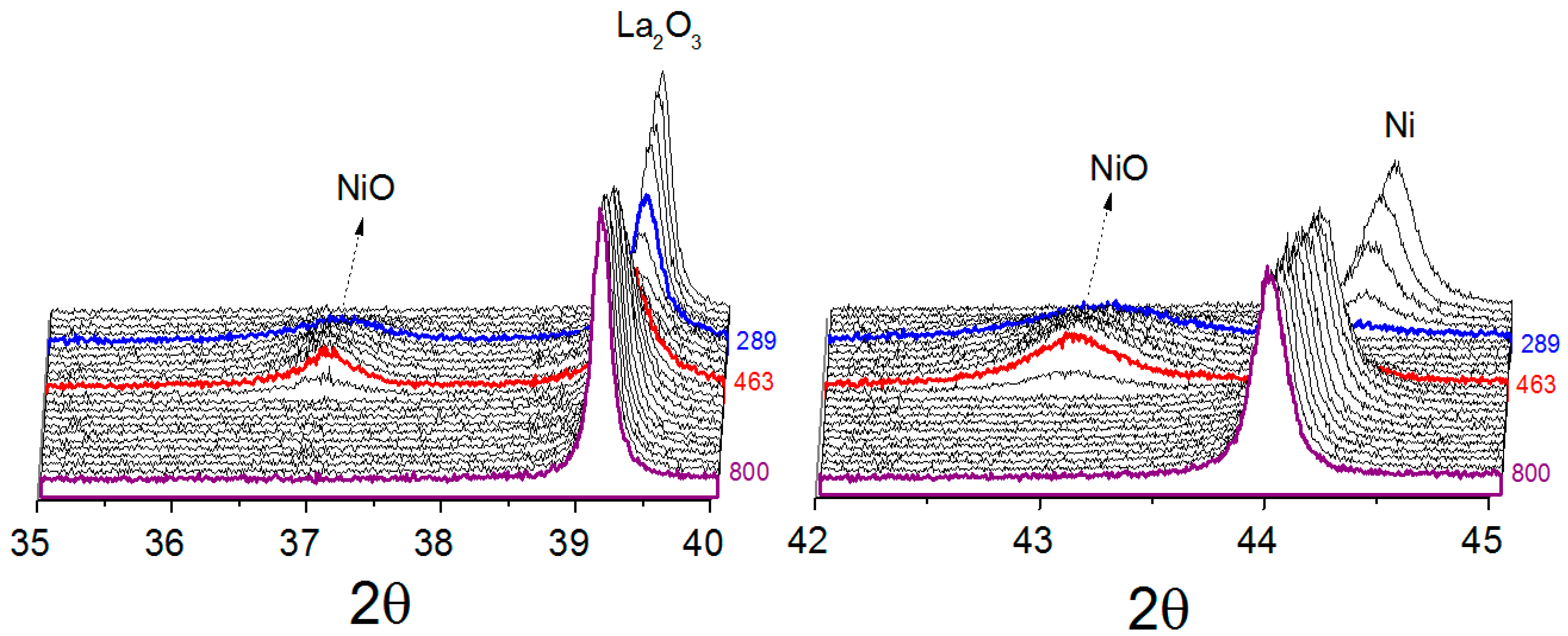
2.3. In Situ X-Ray Diffraction under Reaction Atmosphere (XRD-CH4/CO2)
With the obtained reduced catalysts, their possible evolution under a reaction atmosphere was then studied.
Figure 3 and
Figure 4 show the phases of evolution when the catalysts were exposed to a CH
4/CO
2 mixture from room temperature to 800 °C.
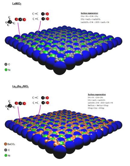
For all catalysts, metallic nickel was oxidized at low temperature to nickel oxide when exposed to the reaction atmosphere, suggesting that CO
2 was responsible for the nickel oxidation. Comparing the catalysts obtained from LaNiO
3 and La
0.8Ba
0.2NiO
3, it was found that the metallic nickel present in reduced LaNiO
3 catalyst is more susceptible to oxidation. At 289 °C, the diffraction lines associated to the La
2O
3 phase decreased in intensity and the diffraction line (111) attributed to metallic nickel was no longer detected, demonstrating that the metallic nickel was destroyed. At 344 °C, the diffraction lines of NiO, (PDF card 00-036-1230), started to appear, reaching a maximum at 463 °C. At around 463 °C, the line (111) attributed to metallic nickel starts to be detected, suggesting the catalyst was being regenerated. For the catalyst obtained from La
0.8Ba
0.2NiO
3, the oxidation event takes place at higher temperatures, starting at about 432 °C and ending at 610 °C. Furthermore, the nickel sites were not totally oxidized, suggesting only a partial oxidation process, which was characterized mainly by the decrease in the (111) metallic nickel diffraction line intensity. A likely explanation of this effect is the possibility of the partial blockage of nickel sites by BaCO
3 during the reduction process, making them less susceptible to oxidation. At temperatures higher than 610 °C orthorhombic-to-hexagonal phase transition of BaCO
3 was observed. This was expected since the literature has reported the orthorhombic-hexagonal transition at high temperatures [
30,
31]. The catalyst obtained from NiO/La
2O
3, similarly to LaNiO
3 catalyst, showed the re-oxidation of metallic nickel to NiO by the reaction mixture, before its new reduction. In summary, with increasing temperature, the main diffraction lines of Ni, La
2O
3 and BaCO
3 for all catalysts shift in a non-parallel way in 2θ axis.
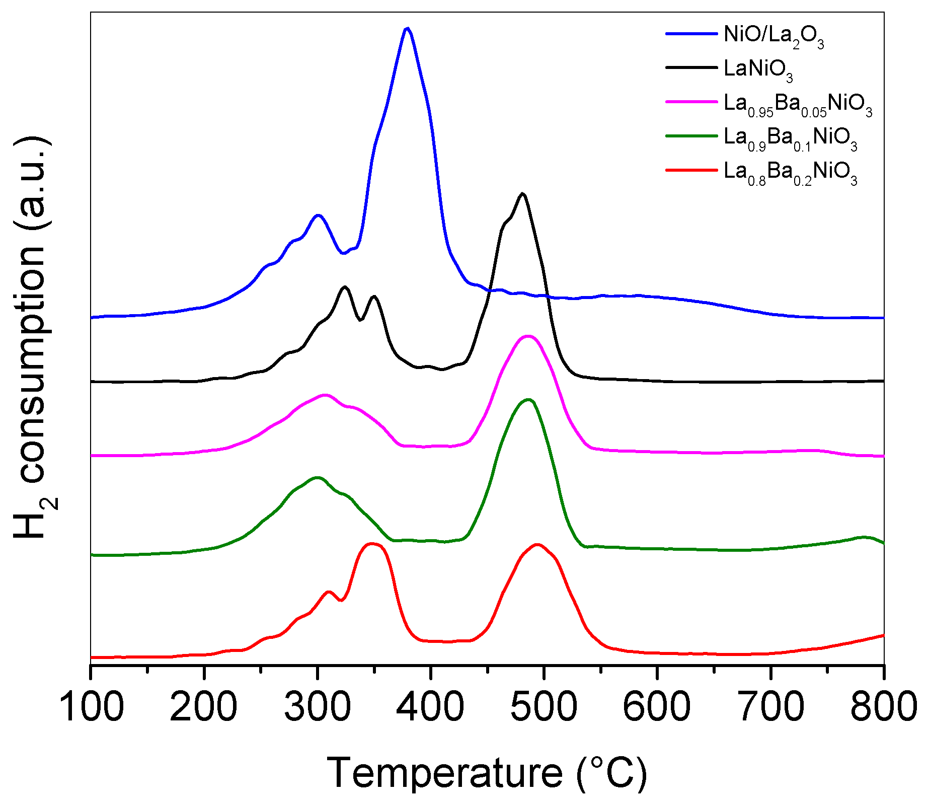
2.4. Temperature-Programmed Reduction (TPR- H2)
The TPR-H
2 profiles of the precursors La
1−xBa
xNiO
3 (x = 0.0, 0.05, 0.1, and 0.2),
Figure 5, showed that these precursors have a similar reduction profile, where two main reduction events were identified. The first one, in the range 250–360 °C, was attributed to the reduction of LaNiO
3 to La
2Ni
2O
5, Equation (5), and the second one, in the range 478–502 °C, was attributed to the transformation of La
2Ni
2O
5 to metallic nickel and La
2O
3, Equation (6). These results are in good agreement with the X-ray results previously discussed and the literature data [
32], where the LaNiO
3 reduction process also occurred in two main events.
According to the perovskite reduction reaction stoichiometry, Equations (5) and (6), the area under the second peak should ideally be twice that of the first peak. Changes in that ratio implies that reducible species other than LaNiO3 are present in the system. In fact, for all the perovskite precursors, ratios lower than the theoretical ones were found. These decrease to a minimum when Ba-substitution reaches a maximum, suggesting the segregation of other reducible phases (or species). In the range 316–391 °C a reduction event was identified and attributed to NiO reduction. This is in total agreement with the X-ray diffraction where nickel oxide was reduced in that temperature range. In addition, the TPR-H2 results showed that Ba-substitution, in general, shifts the final reduction temperature to higher values.
In the case of NiO/La
2O
3, the sample shows two sets of reduction events. The low temperature events were attributed to the reduction of bulk NiO and to NiO species weakly bound to La
2O
3. The second set of NiO reduction events occurred at temperatures close to 600 °C. The corresponding NiO species with stronger interaction with support may generate Ni particles which are more stable and less prone to sintering [
33,
34,
35].
3. Stability Tests
The onset of catalytic activity in DRM of the various catalysts was qualitatively measured by temperature-programmed surface reaction tests, which is temperature-ramped experiments under CH4/CO2/Ar flow; the experiments were performed after in situ reduction at 800 °C of the precursors. The results are not reported for the sake of brevity. It is herein briefly mentioned that incipient conversion of reactants was observed at about 350–400 °C over the Ba-free and Ba-containing perovskites. Interestingly, the onset of the reaction was accompanied by the unique production of H2O and CO which grew with increasing temperature; only at temperature higher than 550–600 °C H2 was progressively produced and H2O concentration declined in line with the chemical thermodynamics.
The NiO/La2O3 catalyst showed similar trends although “delayed” at higher temperatures, thus indicating a lower activity of the catalyst obtained by impregnation than the corresponding catalyst obtained by co-precipitation of perovskite precursor.
These preliminary experiments allowed to identify 700 °C as a suitable temperature for measuring the catalyst stability under reacting conditions. The characterization results also support the assumption that at this temperature Ni is fully reduced in all the formulations.
The catalyst activity was then tested using a feed of CH
4/CO
2/Ar = 25/25/50 mL·min
−1 (GHSV = 2 × 10
5 NL·h
−1·kg
−1) along 24 h on stream at 700 °C (after reduction in H
2/He flow at 800 °C). The results of the experiments are reported in
Figure 6.
During the first 4 h on stream, the catalyst LaNiO
3 showed a continuous increase of the activity followed by a substantial stabilization. H
2 and CO molar fractions showed analogous trends stabilizing around 17 and 35%, respectively. Verykios et al. [
26,
36] observed similar trends and suggested that during the reaction initial hours (induction period) substantial changes occur on the catalyst; in particular, FTIR results suggested that the increase of activity could be associated with the increase of La
2O
2CO
3 and formate species concentration, which were believed intermediate species of the dry reforming process [
8,
11,
26]. The tests on the impregnated NiO/La
2O
3 catalyst showed a rapid decay of conversion and syngas yield.
The relative activity of the two systems is qualitatively in line with the different dispersion of Ni, as revealed by the XRD measurements. The average nickel crystallite size calculated from the diffraction line at 2θ = 44.4° by using the Scherrer equation corresponded in fact to 19 nm in LaNiO3 catalyst and 40 nm in the NiO/La2O3 catalyst, as above mentioned.
It is beyond the scope of the present study to speculate on the reaction mechanism; however, a broad exam on DRM over NiLa-based catalysts supports the picture of CH
4 being activated over Ni sites (thus supporting an expected effect of Ni dispersion), while La-sites would be preferentially involved in CO
2 activation. According to Verykios et al. [
26,
36], the reaction pathway would involve the formation and interaction of C-Ni and La
2CO
2O
3 intermediates.
The Ba-containing formulations La1−xBaxNiO3 (x = 0.1 and 0.2) showed a somehow intermediate level of initial activity, shorter induction period than the Ba-free catalyst and appreciable stability; the conversions of CH4 and CO2 showed a moderate decline with time on stream, as the molar fractions of H2 and CO. The decay of activity was attributed to the insertion of barium which leads to changes in the catalysts’ structure as well as the presence of BaCO3 that may cover part of the active sites and inhibit the interaction with the reactants to a certain degree.
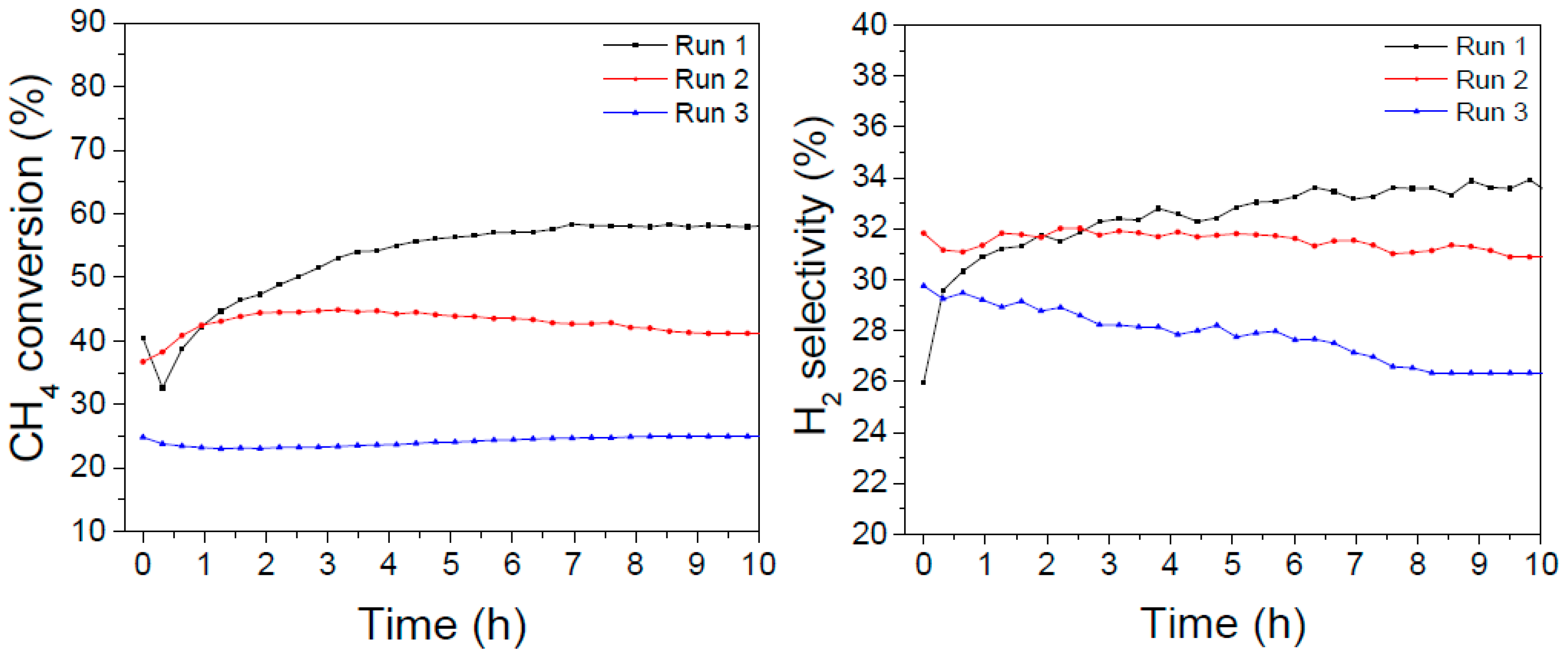
4. Aging Tests
In order to further verify the catalysts’ stability against more stressful treatments, sequential cycles were performed in which a DRM experiment at 700 °C was performed for 10 hours on stream, then the reactor was cooled down to ambient temperature and then re-heated at 700 °C and exposed again to the reacting mixture. Afterwards, an oxidizing treatment at 800 °C and a following reducing treatment at 700 °C were performed; finally, a third DRM experiment at 700 °C was performed and parameters were monitored along 10 hours on stream. The results are reported in
Figure 7 and
Figure 8.
The LaNiO
3 catalyst showed initially the highest activity (with a maximum of about 57% conversion after some hours on stream, consistently with the long-term experiments reported in
Figure 6); in the second cycle the activity levelled off at about 40%, but after the oxidizing/reducing treatments the conversion dropped at about 25% with a final H
2 selectivity of 27%.
In the case of the La0.8Ba0.2NiO3 catalyst, the initial conversion was lower but more stable (between 40–45% after 20 hours on stream) and after the oxidizing/reducing treatments it was affected to a lesser extent, since it declined to about 35% but kept almost constant along the following 10 hours on stream. The H2 selectivity amounted to about 28% in the first 20 hours and dropped to 24% in the third DRM experiment.
These results suggest that the addition of barium promotes a higher resistance to poisoning and sintering processes that are considered side effects of multiple temperature treatments and to the presence of carbon-forming precursors.
5. Temperature Programmed Oxidation (TPO)
TPO experiments were performed on the spent catalysts after 20 h on stream. As can be seen in
Figure 9, the aged LaNiO
3 catalyst showed an intense CO
2 formation, with a maximum close to 600 °C, which was assigned to oxidation of graphitic carbon.
The amount of carbon deposited on catalysts during reaction, deduced from the CO
2 formation during TPO, is reported in
Table 1.
LaNiO
3 showed the largest amount of carbon which is a consequence of its higher activity, at least in part. Barium-containing catalysts showed a less intense CO
2 peak and a substantial decrease in deposited carbon content (~55 lower than LaNiO
3), which could be a consequence of a lower activity. Moreover, although the La
0.9Ba
0.1NiO
3 and La
0.8Ba
0.2NiO
3 catalysts showed similar performances, the higher barium content promoted the lower amount of deposited carbon. It was proposed that catalysts obtained from perovskite reduction are regenerated via La
2O
2CO
3, formate species and carbon oxidation via adsorbed water [
8,
26]. Nevertheless, in order to explain the considerable decrease in carbon deposition for barium-containing catalysts, an extra carbon oxidation pathway is suggested.
According to the literature, BaCO
3 plays a key role in carbon catalytic oxidation. Barium carbonate and carbon species can interact to form a carbonate-carbon complex that decomposes rapidly to carbon monoxide [
37,
38]. The steps are presented by Equations (7) and (8):
If this process was considered, it would be possible to explain the higher resistance of barium-containing catalysts to carbon deposition. It is worth mentioning that the CO
2 present in the feed may promote the BaCO
3 regeneration, since this phase is present in all temperature ranges to which the catalyst was exposed to the CH
4/CO
2 mixture (
Section 2.3).
6. Materials and Methods
6.1. Precursor Synthesis
The perovskite precursors La
1−xBa
xNiO
3 (x = 0.0, 0.05, 0.1, and 0.2) were prepared by citrate method [
8]. A stoichiometric amount of Ni(NO
3)
3·6H
2O (Sigma-Aldrich, St. Louis, MO, USA) solution was added to a citric acid solution at 40 °C under constant stirring for 1 h. The molar ratio citric acid and metal of 1.5:1 was used. After that, the system was heated to 90 °C and the La(NO
3)
3·6H
2O (Sigma-Aldrich) and Ba(NO
3)
3·6H
2O (Sigma-Aldrich, St. Louis, MO, USA) solutions were added. Following the complexation, the solution was evaporated, and the resulting material pre-treated at 300 °C for 2 h to obtain a primary powder and calcined at 800 °C under air flow (50 mL min
−1) for 4 h. The reference precursor NiO/La
2O
3 (La
2O
3 Sigma-Aldrich, St. Louis, MO, USA) was prepared by incipient wetness impregnation. An aqueous solution of nickel nitrate, with 23 wt% Ni content, the same nickel content as the perovskite precursors, was added to a La
2O
3 suspension and stirred for 24 h. Then, the suspension was dried at 100 °C for 12 h, and the resulting solid calcined at 500 °C.
6.2. BET Specific Surface Area
Specific surface area measurements for the calcined samples were performed using the BET method. The analysis was performed at −196 °C using a NOVA–2000 volumetric adsorption system (Quanta Chrome Corporation, Boynton Beach, FL, USA). All the samples were pre-treated at 350 °C under vacuum for 2 h before measurement.
6.3. X-Ray Diffraction (XRD)
X-ray diffraction measurements of calcined precursors and of the reduced catalysts were performed on a Shimadzu XRD-6000 diffractometer using Cu Kα (λ = 1.5418 Å). The diffractograms were collected in 2θ range (20–60°) in steps of 0.25° min−1. For the reduced catalysts diffraction pattern measurements, the samples were pre-reduced at 800 °C (10 °C min−1) under 10.0 vol% H2/He(balance) flow at a rate of 30 mL min−1. The system was cooled down to room temperature under He flow and the diffractograms were collected. These characterization and reduction procedures were performed in an Anton–Paar reaction chamber HTK 1200 coupled to a Shimaden SR52 temperature controller (Shimaden, Nerima Ku, Japan).
6.4. In Situ X-ray Diffraction
In situ XRD experiments were performed to study the evolution of the phases under reducing and reaction atmospheres during temperature increase. The measurements were performed at Synchrotron Light Source–Campinas in a XPD beamline (Huber, Rimsting Germany). The diffractograms were collected in 2θ range (20–60°) in steps of 2° min−1 using λ = 1.5498 Å, which was suitable to identify the phases evolution as well as to obtain a good diffraction line resolution for phase identification. In the case of the reduction study, the precursors were exposed to 5.0 vol% H2/He(balance) flow at a rate 30 mL min−1 from room temperature to 800 °C. For the catalyst study under reaction atmosphere, the precursors were reduced at 800 °C for 30 min and cooled down to room temperature under He flow. Then, the samples were exposed to a 25% CH4/25% CO2/Ar(balance) mixture from room temperature to 800 °C (10 °C min−1) and the diffractograms were collected.
The average nickel crystallite size was calculated from the Ni diffraction line at 2θ = 44.4° at 100 °C by using the Scherrer equation.
6.5. Temperature-Programmed Reduction (TPR)
The TPR profiles were obtained by heating 100 mg of the precursors under 5.0 vol% H2/He(balance) (30 mL min−1) from room temperature to 800 °C at a rate of 10 °C min−1. The experiments were performed in a fixed-bed quartz reactor and the hydrogen consumption was monitored using a multipurpose unit coupled with a gas analyzer Pfeiffer Vacuum Quadrupole Mass Spectrometer Balzers QMS 220 (Pfeifer Vacuum, Annecy, France). The mass fragment to monitor hydrogen signal was (m/z) = 2.
6.6. Reaction Conditions
Long-Term Reactions and Aging Tests
Dry reforming of methane was performed at atmospheric pressure in a stainless-steel tubular reactor. Initially, 30 mg of the precursors were diluted with 90 mg of quartz powder and reduced at 800 °C (10°C min
−1) for 1 h under ultra-pure hydrogen flow at 30 mL min
−1. After pre-reduction at 800 °C, the catalysts were cooled down to 700 °C and purged with N
2 flow. The reaction was carried out at 700 °C for 20 h under 100 mL min
−1 25% CH
4/25% CO
2/Ar
(balance). The effluent gas was analyzed and quantified by using a Shimadzu 2014 chromatograph (Shimadzu, Kyoto, Japan) equipped with TCD detector and a Carboxen 1000 column (Sigma-Aldrich, St. Louis, MO, USA). The reactant conversions (X
j) and product molar fractions (n
i) were calculated according to Equations (9) and (10):
In order to evaluate the catalyst resistance during successive runs, aging tests were performed in the same unit as used in long term experiments. After 20 h on stream at 700 °C, the catalysts were regenerated in the following steps: oxidation at 800 °C for 1 h under synthetic air flow at 30 mL min−1, reduction at 700 °C for 1 h under 30 mL·min−1 of ultra-pure hydrogen and purge under N2 flow at 700 °C. Subsequently, the catalysts were exposed to reaction conditions.
6.7. Temperature-Programmed Oxidation (TPO)
The amount of carbon deposited on the spent catalysts was analyzed by temperature-programmed oxidation. After the long-term tests, the catalysts were cooled down to room temperature under Ar flow, and then exposed to synthetic air flow (30 mL·min−1) from room temperature to 1000 °C at a rate of 10 °C·min−1. CO2 formation was followed by chromatography using a Shimadzu GC-17A (Shimadzu, Kyoto, Japan) set-up equipped with FID and TCD detectors and a Carboxen 1006 column (Sigma-Aldrich, St. Louis, MO, USA).

 ,
, 


