Thermal Deactivation of Rh/α-Al2O3 in the Catalytic Partial Oxidation of Iso-Octane: Effect of Flow Rate


Laboratory of Catalysis and Catalytic Processes, Dipartimento di Energia, Politecnico di Milano, via La Masa 34, 20156 Milano, Italy
*
Authors to whom correspondence should be addressed.
Catalysts 2019, 9(6), 532; https://doi.org/10.3390/catal9060532
Submission received: 20 May 2019
/
Revised: 11 June 2019
/
Accepted: 12 June 2019
/
Published: 14 June 2019
(This article belongs to the Special Issue Catalysts Deactivation, Poisoning and Regeneration)
Abstract
:Catalytic partial oxidation (CPO) of logistic fuels is a promising technology for the small-scale and on-board production of syngas (H2 and CO). Rh coated monoliths can be used as catalysts that, due to Rh high activity, allow the use of reduced reactor volumes (with contact time in the order of milliseconds) and the achievement of high syngas yield. As the CPO process is globally exothermic, it can be operated in adiabatic reactors. The reaction mechanism of the CPO process involves the superposition of exothermic and endothermic reactions at the catalyst inlet. Thus, a hot spot temperature is formed, which may lead to catalyst deactivation via sintering. In this work, the effect of the flow rate on the overall performance of a CPO-reformer has been studied, using iso-octane as model fuel. The focus has been on thermal behavior. The experimental investigation consisted of iC8-CPO tests at varying total flow rates from 5 to 15 NL/min, wherein axially resolved temperature and composition measurements were performed. The increase of flow rate resulted in a progressive increase of the hot spot temperature, with partial loss of activity in the entry zone of the monolith (as evidenced by repeated reference tests of CH4-CPO); conversely, the adiabatic character of the reformer improved. A detailed modelling analysis provided the means for the interpretation of the observed results. The temperature hot spot can be limited by acting on the operating conditions of the process. However, a tradeoff is required between the stability of the catalyst and the achievement of high performances (syngas yield, reactants conversion, and reactor adiabaticity).
1. Introduction
Nowadays, the industrial sector (mining, manufacturing, agriculture, construction, and others) accounts for the largest share in energy consumption all around the world. According to IEA, the transportation sector ranks at the second position in terms of energy consumption and projections show that, in the 2015–2040 period, its demand for energy will grow more quickly than the industrial field, reaching 1%/year, 0.3% higher than the industrial rate [1]. To supply this ever-increasing demand, while coping with the commitment to mitigating CO2 emissions, fuel cell and hydrogen technology can be a key player [2,3]. The final goal of a green energy market is the full exploitation of renewable energy sources (with H2 production via water electrolysis); however, the development of a decentralized H2-production and supply chain based on small scale processors represents a realistic transition strategy [4,5,6,7]. Small-scale reformers have also been proposed for the on-board applications of H2 (fueling of auxiliary power units based on fuel cells, the injections in the combustion chamber, and the regeneration of catalytic traps) in view of an improvement of the vehicle efficiency [8,9,10,11].
Natural gas, LPG, and liquid hydrocarbons can be converted catalytically into hydrogen-rich steams by steam reforming (SR) and catalytic partial oxidation (CPO). The use of noble metal-based catalysts is an important aspect of the process intensification, since higher activity allows for smaller catalyst inventory and faster dynamic response. Furthermore, such catalysts reduce the risk of coke formation with respect to non-precious metals as Ni and Fe [12,13]. Operating at very short contact times mitigates the cost issues associated with the adoption of precious metal catalysts. Among noble metals, Rh was reported to provide the highest activity and lower the tendency to coke formation at typical CPO conditions [4,14,15].
Concerning the reactor design, steam reforming of methane is an already consolidated industrial technology based on multi-tubular reactors but the necessity of a large energy input due to its high endothermicity makes the reactors hardly scalable down to small sizes (1–10 kW) of interest for distributed applications [2,16,17,18,19]. Instead, the catalytic partial oxidation (CPO) of hydrocarbons is a more flexible technology as it is globally exothermic and can be carried out in simple adiabatic structured reactors that are easily scalable.
The autothermal operation of the so-called short contact time CPO reformers has been successfully demonstrated by the pioneering and extensive work of Lanny Schmidt and coworkers, who have shown the obtainment of high syngas yields via partial oxidation of gaseous and vaporized liquid hydrocarbons over Rh washcoated foams [20,21,22,23]. The results from the Minnesota group have been largely confirmed in the years by several groups [24,25,26,27]. Besides, the development of advanced experimental and modelling tools has significantly contributed to the comprehension of the transport and chemical phenomena that govern the performance of CPO reformers [28]. Basini and co-workers have addressed a comprehensive analysis of the reduction of investment costs and energy consumption, the flexibility towards feedstock composition and product capacity, and the simplicity of technical and operational processes [29].
In previous works, the authors have reported the results of recent studies on the autothermal CPO of model hydrocarbons, representative of logistic fuels: iso-octane (iC8), a model for gasoline; and n-octane, a model for diesel [19,30]. The measurement of axially resolved temperature and concentration profiles and the engineering analysis of the reactor by the means of mathematical modelling have shown that the CPO of logistic fuels is a more severe process than the CPO of light hydrocarbons, being characterized by a higher peak surface temperature and the onset of gas-phase reactions leading to the formation of coke precursors; both factors can significantly contribute to accelerate catalyst deactivation by sintering and coking [17,19,30].
In this work, the effect of the input load on the performance of an iC8-CPO reformer was investigated by both experimental and modelling approaches. Flow rate is a key parameter of the reformer performance; it affects the reaction pathways, the output product yield, and the extent of heat dissipations. In turn, these factors can significantly impact the thermal behavior of the reactor and, consequently, the catalyst stability. At this scope, experiments and calculations were performed for a 400/7 CPSI cordierite honeycomb monolith, coated with a 2 wt% Rh/ α-Al2O3 active phase.
2. Results and Discussion
2.1. Conversion and Selectivity Performances
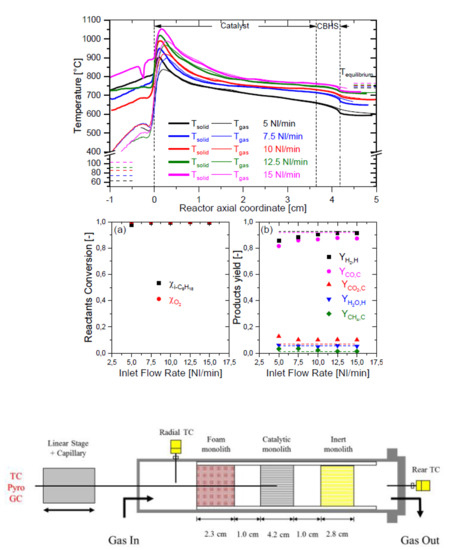
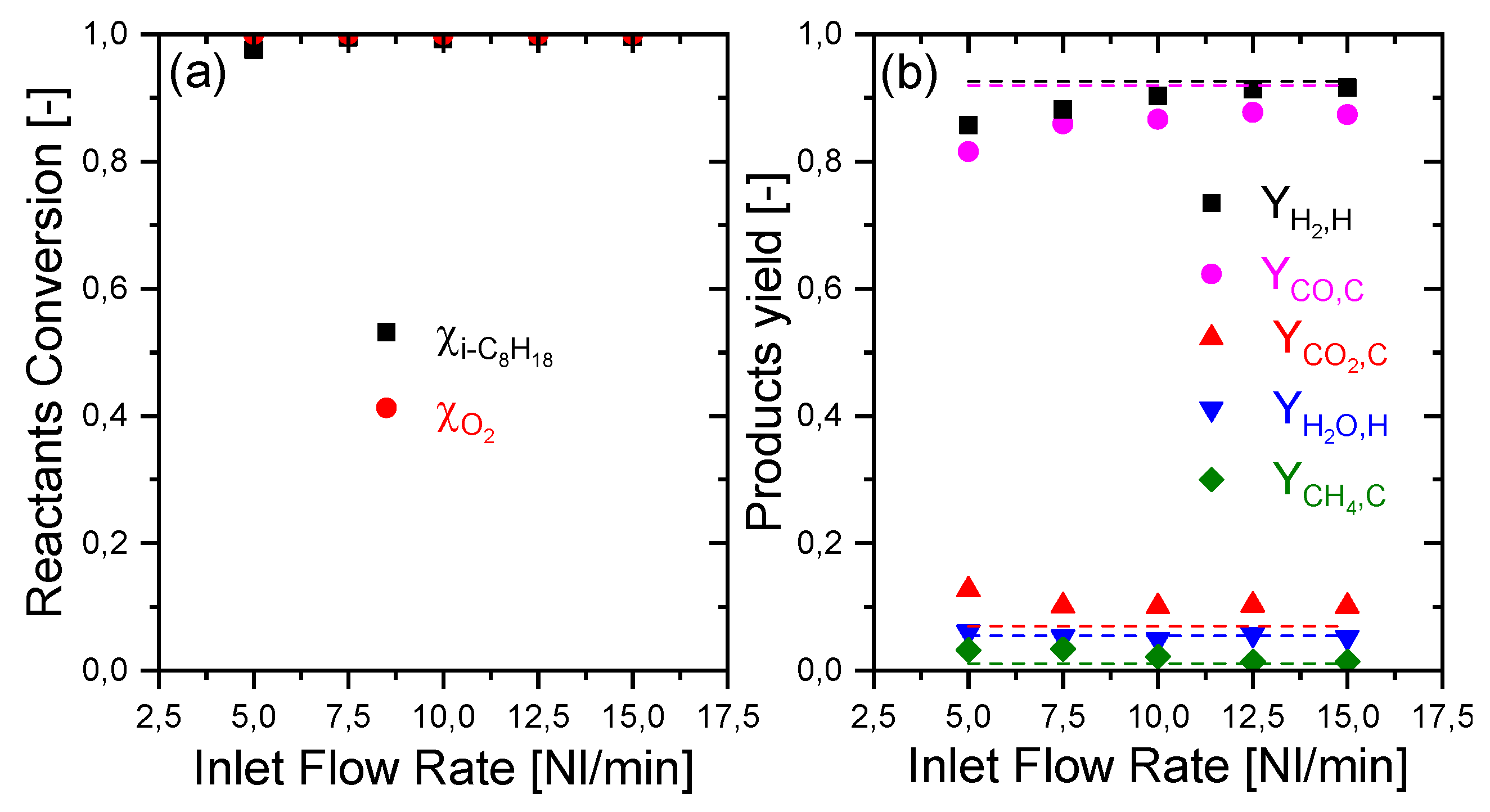
Experiments of iC8-CPO were performed at constant feed composition (iC8, Air, N2 with 3% iC8 and C/O = 0.9) and varying total flow rate from 5 to 15 NL/min; Figure 1 reports the integral results of the experiments in terms of reactant conversions and product yields.
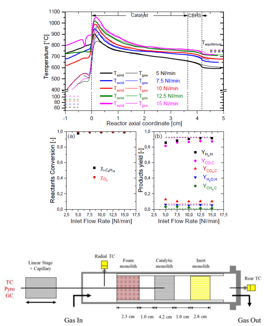
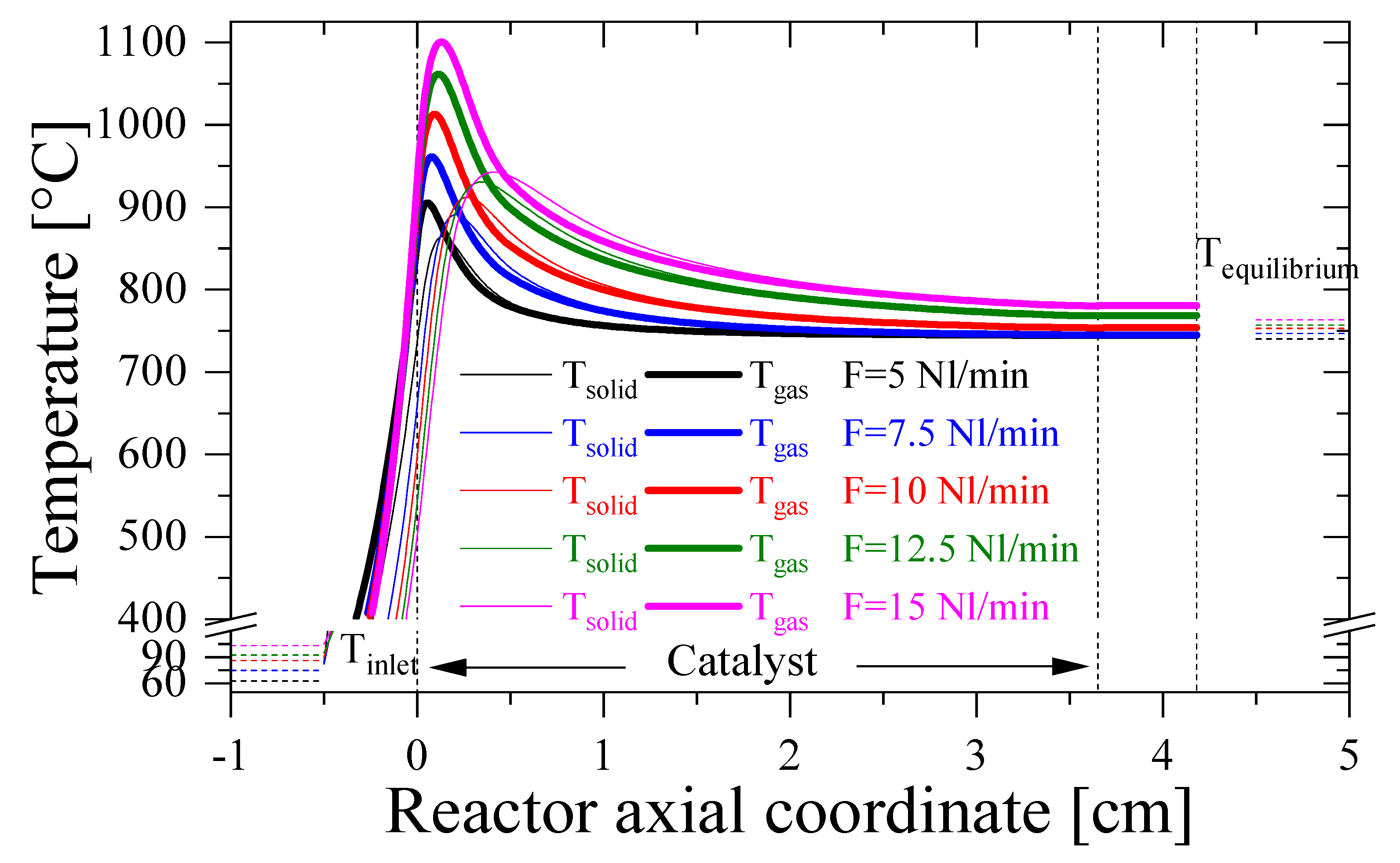
It was verified that O2, the limiting reactant, was fully converted under all the conditions. Except in the case of 5 NL/min, iso-octane was also completely converted since its conversion was not limited by thermodynamics. At increasing flow rate, the selectivity and yield of H2 and CO increased, progressively approaching the expected equilibrium values under adiabatic conditions (dotted lines in Figure 1). The yields of CH4, CO2, and H2O, instead, moderately decreased and tended to the calculated equilibrium values as inlet flow increased. This result might appear counter-intuitive, considering the indirect-consecutive nature of CO and H2 formation and the expected negative effect of reducing the contact time on the formation of terminal products. However, the axial evolution of temperature profiles changed considerably at increasing flow rates; the measurements obtained during the iso-octane experimental campaign are presented in Figure 2, where thin lines represent the measurements obtained by the thermocouple (representative of the gas-phase temperature), while thicker lines represent the measurements obtained from the optical-fiber/pyrometer system (representative of the emitting surface temperature).
The temperature of the catalyst surface and of the gas phase measured along the entire axial coordinate increased significantly with the increase of flow rate. Several factors have a role in this trend, including operational, thermodynamic, and kinetic factors.
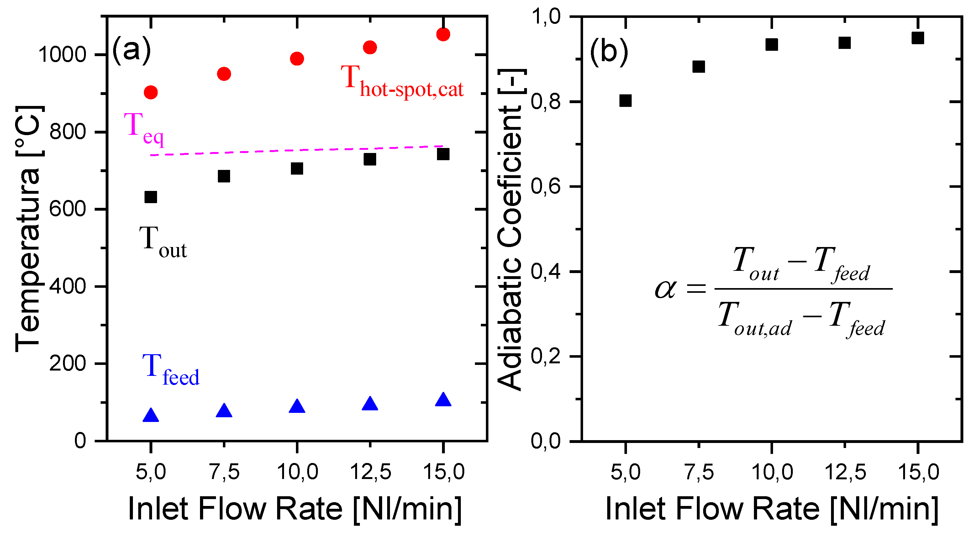
First, the inlet temperature increased with the flow rate from a value of 62 °C (at 5 NL/min) to 103 °C (at 15 NL/min) because of the enhanced heat exchange between the pre-heating cartridge and the gas flow with increasing flow rate. Thus, the adiabatic equilibrium temperature also increased; the single values calculated for the various experiments are reported as short dotted bars at the right-hand side of Figure 2. Secondly, as better shown in Figure 3a, the measured outlet temperature increased more markedly than the adiabatic temperature; thus, the difference between the outlet adiabatic equilibrium temperature and the outlet measured temperature decreased with the increase of the flow rate.
In other words, at increasing load, the reactor better approached the adiabatic behavior. This effect can be quantified through the definition of an adiabaticity coefficient, expressing the ratio between the measured temperature rise across the CPO reactor and ideal temperature rise for the fully adiabatic reactor, as follows:
As shown in panel (b) of Figure 3, the adiabaticity coefficient increased significantly with the flow rate, passing from a value of 80% in the case of 5 NL/min, to 93% in the case of 10 NL/min, and finally to 95% in the case of 15 NL/min. This trend reveals the impact of heat dispersions on the thermal balance of the reactor or, in other words, the relative impact of heat dispersion over heat load. The data clearly show that although heat dispersions expectedly grew on absolute basis due to the progressive increase of the reactor temperature, the ratio between heat dispersion and the inlet enthalpy flux entering the reactor decreased. The criticality of obtaining a full adiabatic behavior at the lab scale is well known, and this is especially true when dealing with miniaturized systems, given the high surface-to-volume ratio; thus, the experiments were extremely important to verify the sensitivity of the system to a key parameter as input flow. It was concluded that at total flows above 10 NL/min, the CPO reactor can be treated as fully adiabatic.
Lastly, it is observed that another important phenomenon was the increase and enlargement of the hot spot region at increasing flow rate (as shown in Figure 2 and highlighted in Figure 3, panel (a)), which cannot be explained by the above-mentioned factors. A modelling analysis was thus performed to understand more deeply the kinetic effects involved in the temperature profile, and its dependence on flow rate.
2.2. Modeling Analysis
To gain insight into the correlation between inlet flow rate and hot spot temperatures, the reactor was simulated, assuming a perfect adiabatic behavior. The predicted gas-phase and solid phase temperature profiles are reported in Figure 4.
Notably, a progressive enlargement of the hot spot is predicted; in fact, the decline of the temperature downstream of the maximum becomes more gradual at increasing flow, such that at any flow rate, the consumption of O2 is more rapid than the consumption of i-C8 and the formation of CO and H2 starting from the very entrance of the monolith. Thus, the heat release occurs across a shorter distance than heat consumption, which originates from the hot spot at the entrance.
The simulated concentration profiles are reported in Figure 5.
Panels (a) and (b) present a progressive extension of the iso-C8H18 and O2 consumption zones with inlet flow increase. In fact, a higher flow rate corresponds to a higher velocity of the gas phase inside the reactor; thus, there is an expected delay of consumption of the reactants. In particular, the O2—consumption length (Figure 5b) grows from 0.25 cm (5 NL/min) to 0.75 cm (15 NL/min). This region is the so-called oxy-reforming zone, where the hot spots develop as the result of the balance between exothermic reactions responsible for O2 consumption (mainly H2 oxidation) and endothermic reactions responsible for the fuel consumption (iC8 steam reforming to CO and H2) [31].
However, the balance between exothermic and endothermic reactions can change. This is more clearly shown in Figure 6, where the conversion profiles of the reactants are plotted in the various flow conditions; taking the coordinate 0.25 cm as a reference, here the oxygen conversion moves from 98% at 5 NL/min to 78% at 15 NL/min. On the other hand, iso-octane conversion moves from 88% of 5 NL/min to 53% of 15 NL/min. Thus, the exothermic contribution increases over the endothermic one and temperatures grow consequently. A change of selectivity is also produced, leading to an increased concentration of H2O and CO2 a decreased concentration of CO and H2.
Such an unbalancing of exothermic and endothermic contributions is fuel-specific, being related to the slow diffusivity of i-C8, which enhances the consecutive nature of the surface process [2], and to its high gas phase reactivity, which results in the onset of homogeneous reactions upon an ignition delay. The onset of gas phase reactions is progressively shifted downstream on increasing the flow rate, as evidenced by the change of slope of iC8 conversion curves in Figure 6. In addition to this fuel-specific effect, there is also a general trend associated with the increase of gas velocity in CPO processes: at increasing importance of convection, conduction is less effective in smoothing the surface hot spot [32].
2.3. Catalyst Stability
The effect on the catalyst stability of performing iC8 experiments at increasing flow rate, and thus the effect of exposing the catalyst to progressively temperature increase, was verified by systematically repeating methane CPO tests; these were carried out on the fresh catalyst and after every iso-octane CPO test.
The reactor integral performance was measured, and the results are reported in Table 1, in terms of reactant conversion and product selectivity. Negligible differences were observed between the experiment on fresh catalyst and the following tests, and a close approach to thermodynamic equilibrium was found.
More sensitive data were, however, obtained from the axially resolved temperature measurements shown in Figure 7.
The outlet temperature remained aligned with the adiabatic equilibrium, but changes of the temperature profiles were observed in the entering zone. In fact, the fresh catalyst showed a hot spot of temperature of about 780 °C and flattening of the solid and gas temperature profiles (which indicates where the system approaches the thermodynamic equilibrium) at about 1.5 cm from the entrance. Test after test, the maxima measured by the thermocouple and the pyrometer, as well as the axial extension of the hot spot, increased. After the iC8 experiment at 15 NL/min, the hot spot temperature measured by the optical fiber amounted to 856 °C, while the flattening of the solid and gas-phase temperatures was observed in correspondence with the coordinate of 2.5 cm.
This is the clear evidence of a progressive deactivation of the catalyst, likely due to sintering of Rh clusters after exposure to temperature exceeding 900 °C in the iC8 experiments. The phenomenology of deactivation has been discussed in previous works from this and other research groups [14,32,33]. Since O2 consumption in the oxidation reactions is fully mass transfer controlled, while CH4 consumption via steam reforming is more chemically controlled, a loss of surface sites will preferentially affect the steam reforming reaction, with a consequent loss of the heat consumption rate and thus an increase of temperatures in the oxy-reforming zone.
Despite the deactivation probed by the temperature measurements, the evidence that equilibrium conversion and syngas yield were still reached in every CH4 CPO test confirms that the monolith was sufficiently oversized for keeping a stable methane CPO application.
Taking into consideration all the results obtained, methane CPO tests confirm that, when feeding a logistic fuel such as iso-octane, a flow rate of 10 NL/min is a relatively safe condition that is able to preserve catalyst stability and avoid an important deactivation via sintering.
3. Materials and Methods
3.1. Catalyst Synthesis, Structural and Morphological Characterizations
The catalyst evaluated in this work is a sample of 400/7 cordierite honeycomb monolith, coated with a 2 wt% Rh/ α-Al2O3 active phase. The Rh/α-Al2O3 catalytic powder was synthesized by incipient wetness impregnation of α-Al2O3 with Rh(NO3)3 solution, followed by drying at 120 °C overnight. Surface area and pore size volume of the catalyst powders, respectively, 5 m2/g and 0.21 mL/g, were determined by N2 adsorption–desorption at 77 K with the BET method using a Micromeritics TriStar 3000 instrument. Rhodium content, 1.71% w/w, was determined by ICP-MS using a XSeries instrument.
Rh dispersion on the catalyst powders was estimated by hydrogen pulse chemisorption using a TPD/R/O 1100 Thermo Fischer Instrument. A pre-treatment was performed consisting of an initial reduction with a 5% H2/Ar flow (50 Ncm3/min) from room temperature up to 500 °C (heating rate 7 °C/min). After 1h at 500 °C, the sample was cooled down to 40 °C in pure Argon. The chemisorption was performed with 20–30 pulses (0.86 Ncm3) of the same diluted H2 mixture. Ageing experiments under reaction atmosphere were performed in order to evaluate the catalyst stability using mild (4% CH4, C/O = 0.9, N2 to balance) and severe (27% CH4 in air with C/O = 0.9) conditions, ramping the temperature from R.T to 850 °C (heating rate 10 °C/min, 850 °C hold for 4h) at GHSV = 80,000 NL/kg/h. The results of chemisorption on the fresh and aged catalysts are presented in Table 2, showing a progressive decrease of Rh dispersion from 69% for the as prepared catalyst to 7% under severe ageing conditions, which resemble those achieved in the adiabatic reactor.
After drying, the catalyst powders were suspended with water and nitric acid before undergoing a 24h-long ball milling. The coating proceeded through the dip-coating technique. Further details on synthesis methodology can be found elsewhere [34].
Aiming to verify the presence of heat losses along the reactor, the monolith was partly uncoated, in the rear part, forming a continuous back heat shield (CBHS), being completely coated at the entrance and avoiding a continuous front heat shield, thus reducing the hot spot temperature.
Table 3 reports the characteristics of the catalyst used in this work.
The catalysts were inserted in a quartz pipe between a FeCrAlloy 15 ppi foam and an inert cordierite monolith inserted in such a way to guarantee downstream position to the back-heat shield.
3.2. Experimental Setup
A capillary (ID 320 µm), carefully allocated in a central channel of the catalyst, was capable to slide along the axial coordinate, as the reactor is equipped with spatially resolved sampling apparatus. Two different types of capillaries are employed in alternance: a (ID = 200 µm, OD = 350 µm), opened at its tip, allowing collecting gas samples and a second capillary (OD = 500 µm), closed at its tip, used to host the 250 µm K-Type thermocouple or a 45° ground optical fiber. Optical fiber and thermocouple are used to collect, respectively, the temperatures of the solid and gas phase. An Agilent MicroGC 3000A equipped with two columns (Plot U and a Molecular Sieve, Agilent, Santa Clara, CA, USA) was used to determine the gas phase concentration of different species. Plot U was operated at 60 °C, in order to get better resolution for light hydrocarbons (C1–C4) and then at 160 °C in order to get peaks of small tailing effect. N2 was chosen as internal standard. As Plot U is not capable to separate N2 from CH4, O2, H2, and CO, the Molecular Sieve was used as well.
The effect of the inlet flow rate on CPO of iC8 was conducted with a progressive increase of the total flow from 5 NL/min to 15 NL/min. The inlet concentration of the hydrocarbon was 3%, and the C/O ratio was kept constant and equal to 0.9. The goal of this campaign is to evaluate the adiabaticity of the reactor and the activity of the catalyst. The stability of the catalyst has been evaluated, by performing methane CPO tests on the fresh catalyst and after each iso-octane experiment.
3.3. Reactor Modelling
A mathematical 1D, dynamic, fixed bed, heterogeneous, single channel reactor model was used for the reactor design and for the analysis of experimental results. Its development was presented in previous works [16,34].
The model accounts for axial convection and diffusion, gas–solid transport term, solid conduction, and mass and energy balances for both solid and gas phase (Table 4).
This model is an extension of a previous, already validated methane CPO model, now taking into consideration a catalytic kinetic scheme for i-C8H18 conversion [30]. The gas phase kinetics are also included, as reported in [19].
The kinetic scheme is presented in Table 5.
4. Conclusions
Rhodium supported catalysts, operated in adiabatic reactors, are effective in the small-scale production of synthesis gas from liquid fuels. These features make this process attractive for the development of a compact reformer. Rhodium-based catalysts are able to efficiently reform iso-octane into synthesis gas.
Experiments and model simulations confirm the indirect reaction mechanism, which is responsible for the presence of an oxy-reforming zone in the first part of the catalyst and a reforming zone further downstream.
It has been observed that the increase of the inlet flow rate promotes the adiabaticity of the reactor, but it leads to a higher catalyst hot spot temperature, due to the higher inlet enthalpic flux. The catalyst stability has been evaluated by performing a methane CPO after each octane test. The optimal inlet flow rate has been set to 10 NL/min, the setting that guarantees the best compromise between the adiabaticity of the reactor and the stability of the catalyst.
Author Contributions
The research was completed through the cooperation of all authors. All authors were responsible for the study of concept, data acquisition and interpretation. G.G. and A.B. were responsible for the project’s conceiving and design, being also responsible for drafting and revising the manuscript.
Funding
This research was funded by MIUR—Ministero dell’Istruzione, dell’Università e della Ricerca (Italy) within the PRIN—2015 program, HERCULES project; and by MISE—Ministero dello Sviluppo Economico (Italy) within the Industria 2015 program, MICROGEN 30 project.
Conflicts of Interest
The authors declare no conflict of interest.
References
- U.S. Energy Information Administration. International Energy Outlook 2017; U.S. Energy Information Administration: Washington, DC, USA, 2017.
- Carrera, A.; Beretta, A.; Groppi, G. Catalytic Partial Oxidation of Iso-Octane over Rh/α-Al2O3 in an Adiabatic Reactor: An Experimental and Modeling Study. Ind. Eng. Chem. Res. 2017, 56, 4911–4919. [Google Scholar] [CrossRef]
- Yvonne, R.; Simon, L.; Johannes Pfister, C.D. Fuel Cells and Hydrogen for Green Energy in European Cities and Regions. A Study for the Fuel Cells and Hydrogen Joint Undertaking; Sederanger: Frankfurt, Germany, 2018. [Google Scholar]
- Farrauto, R.J.; Liu, Y.; Ruettinger, W.; Ilinich, O.; Shore, L.; Giroux, T. Precious Metal Catalysts Supported on Ceramic and Metal Monolithic Structures for the Hydrogen Economy. Catal. Rev. 2007, 49, 141–196. [Google Scholar] [CrossRef]
- Heck, R.M.; Gulati, S.; Farrauto, R.J. The Application of Monoliths for Gas Phase Catalytic Reactions. Chem. Eng. J. 2001, 82, 149–156. [Google Scholar] [CrossRef]
- Farrauto, R.; Hwang, S.; Shore, L.; Ruettinger, W.; Lampert, J.; Giroux, T.; Liu, Y.; Ilinich, O. New Material Needs for Hydrocarbon Fuel Processing: Generating Hydrogen for the PEM Fuel Cell. Annu. Rev. Mater. Res. 2003, 33, 1–27. [Google Scholar] [CrossRef]
- Groppi, G.; Tronconi, E. Honeycomb Supports with High Thermal Conductivity for Gas/Solid Chemical Processes. Catal. Today 2005, 105, 297–304. [Google Scholar] [CrossRef]
- Specchia, S. Fuel Processing Activities at European Level: A Panoramic Overview. Int. J. Hydrog. Energy 2014, 39, 17953–17968. [Google Scholar] [CrossRef]
- Kraaij, G.J.; Specchia, S.; Bollito, G.; Mutri, L.; Wails, D. Biodiesel Fuel Processor for APU Applications. Int. J. Hydrog. Energy 2009, 34, 4495–4499. [Google Scholar] [CrossRef]
- Specchia, S.; Tillemans, F.W.A.; van den Oosterkamp, P.F.; Saracco, G. Conceptual Design and Selection of a Biodiesel Fuel Processor for a Vehicle Fuel Cell Auxiliary Power Unit. J. Power Sources 2005, 145, 683–690. [Google Scholar] [CrossRef]
- Kolb, G.; Baier, T.; Schürer, J.; Tiemann, D.; Ziogas, A.; Specchia, S.; Galletti, C.; Germani, G.; Schuurman, Y. A Micro-Structured 5 kW Complete Fuel Processor for Iso-Octane as Hydrogen Supply System for Mobile Auxiliary Power Units Part II—Development of Water–Gas Shift and Preferential Oxidation Catalysts Reactors and Assembly of the Fuel Processor. Chem. Eng. J. 2008, 138, 474–489. [Google Scholar] [CrossRef]
- Hou, Z.; Chen, P.; Fang, H.; Zheng, X.; Yashima, T. Production of Synthesis Gas via Methane Reforming with CO2 on Noble Metals and Small Amount of Noble-(Rh-) Promoted Ni Catalysts. Int. J. Hydrog. Energy 2006, 31, 555–561. [Google Scholar] [CrossRef]
- le Saché, E.; Santos, J.; Smith, T.J.; Centeno, M.A.; Arellano-Garcia, H.; Odriozola, J.A.; Reina, T.R. Multicomponent Ni-CeO2 Nanocatalysts for Syngas Production from CO2/CH4 Mixtures. J. CO2 Util. 2018, 25, 68–78. [Google Scholar]
- Tavazzi, I.; Beretta, A.; Groppi, G.; Maestri, M.; Tronconi, E.; Forzatti, P. Experimental and Modeling Analysis of the Effect of Catalyst Aging on the Performance of a Short Contact Time Adiabatic CH4-CPO Reactor. Catal. Today 2007, 129, 372–379. [Google Scholar] [CrossRef]
- Fichtner, M.; Mayer, J.; Wolf, D.; Schubert, K. Microstructured Rhodium Catalysts for the Partial Oxidation of Methane to Syngas under Pressure. Ind. Eng. Chem. Res. 2001, 40, 3475–3483. [Google Scholar] [CrossRef]
- Maestri, M.; Beretta, A.; Groppi, G.; Tronconi, E.; Forzatti, P. Comparison among Structured and Packed-Bed Reactors for the Catalytic Partial Oxidation of CH4 at Short Contact Times. Catal. Today 2005, 105, 709–717. [Google Scholar] [CrossRef]
- Qi, A.; Wang, S.; Ni, C.; Wu, D. Autothermal Reforming of Gasoline on Rh-Based Monolithic Catalysts. Int. J. Hydrog. Energy 2007, 32, 981–991. [Google Scholar] [CrossRef]
- Costa, D.S.; Gomes, R.S.; Rodella, C.B.; da Silva, R.B.; Fréty, R.; Teixeira Neto, É.; Brandão, S.T. Study of Nickel, Lanthanum and Niobium-Based Catalysts Applied in the Partial Oxidation of Methane. Catal. Today 2018. [Google Scholar] [CrossRef]
- Carrera, A.; Pelucchi, M.; Stagni, A.; Beretta, A.; Groppi, G. Catalytic Partial Oxidation of n-Octane and Iso-Octane: Experimental and Modeling Results. Int. J. Hydrog. Energy 2017, 42, 24675–24688. [Google Scholar] [CrossRef]
- Nogare, D.D.; Degenstein, N.J.; Horn, R.; Canu, P.; Schmidt, L.D. Modeling Spatially Resolved Data of Methane Catalytic Partial Oxidation on Rh Foam Catalyst at Different Inlet Compositions and Flowrates. J. Catal. 2011, 277, 134–148. [Google Scholar] [CrossRef]
- Panuccio, G.J.; Williams, K.A.; Schmidt, L.D. Contributions of Heterogeneous and Homogeneous Chemistry in the Catalytic Partial Oxidation of Octane Isomers and Mixtures on Rhodium Coated Foams. Chem. Eng. Sci. 2006, 61, 4207–4219. [Google Scholar] [CrossRef]
- Wanat, E.C.; Venkataraman, K.; Schmidt, L.D. Steam Reforming and Water–Gas Shift of Ethanol on Rh and Rh–Ce Catalysts in a Catalytic Wall Reactor. Appl. Catal. A Gen. 2004, 276, 155–162. [Google Scholar] [CrossRef]
- Degenstein, N.; Subramanian, R.; Schmidt, L. Partial Oxidation of n-Hexadecane at Short Contact Times: Catalyst and Washcoat Loading and Catalyst Morphology. Appl. Catal. A Gen. 2006, 305, 146–159. [Google Scholar] [CrossRef]
- Donazzi, A.; Maestri, M.; Michael, B.C.; Beretta, A.; Forzatti, P.; Groppi, G.; Tronconi, E.; Schmidt, L.D.; Vlachos, D.G. Microkinetic Modeling of Spatially Resolved Autothermal CH4 Catalytic Partial Oxidation Experiments over Rh-Coated Foams. J. Catal. 2010, 275, 270–279. [Google Scholar] [CrossRef]
- Maestri, M.; Beretta, A.; Faravelli, T.; Groppi, G.; Tronconi, E.; Vlachos, D.G. Two-Dimensional Detailed Modeling of Fuel-Rich H2 Combustion over Rh/Al2O3 Catalyst. Chem. Eng. Sci. 2008, 63, 2657–2669. [Google Scholar] [CrossRef]
- Batista da Silva, R.; Brandão, S.T.; Lucotti, A.; Tommasini, M.S.; Castiglioni, C.; Groppi, G.; Beretta, A. Chemical Pathways in the Partial Oxidation and Steam Reforming of Acetic Acid over a Rh-Al2O3 catalyst. Catal. Today 2017, 289, 162–172. [Google Scholar] [CrossRef]
- Donazzi, A.; Livio, D.; Beretta, A.; Groppi, G.; Forzatti, P. Surface Temperature Profiles in CH4 CPO over Honeycomb Supported Rh Catalyst Probed with in Situ Optical Pyrometer. Appl. Catal. A Gen. 2011, 402, 41–49. [Google Scholar] [CrossRef]
- Beretta, A.; Donazzi, A.; Groppi, G.; Maestri, M.; Tronconi, E.; Forzatti, P. Gaining Insight into the Kinetics of Partial Oxidation of Light Hydrocarbons on Rh, through a Multiscale Methodology Based on Advanced Experimental and Modeling Techniques. Catalysis 2013, 25, 1–49. [Google Scholar]
- Iaquaniello, G.; Antonetti, E.; Cucchiella, B.; Palo, E.; Salladini, A.; Guarinoni, A.; Lainati, A.; Basini, L. Natural Gas Catalytic Partial Oxidation: A Way to Syngas and Bulk Chemicals Production. In Natural Gas—Extraction to End Use; InTech: London, UK, 2012. [Google Scholar] [Green Version]
- Pagani, D.; Batista, R.; Silva, D.; Moioli, E.; Donazzi, A.; Lucotti, A.; Tommasini, M.; Castiglioni, C.; Brandao, S.T.; Beretta, A.; et al. Annular Reactor Testing and Raman Surface Characterization of the CPO of i-Octane and n-Octane on Rh Based Catalyst. Chem. Eng. J. 2016, 294, 9–21. [Google Scholar] [CrossRef]
- Beretta, A.; Groppi, G.; Carrera, A.; Donazzi, A. Analysis of the Impact of Gas-Phase Chemistry in Adiabatic CPO Reactors by Axially Resolved Measurements; Academic Press: Cambridge, MA, USA, 2017; pp. 161–201. [Google Scholar]
- Beretta, A.; Groppi, G.; Lualdi, M.; Tavazzi, I.; Forzatti, P. Experimental and Modeling Analysis of Methane Partial Oxidation: Transient and Steady-State Behavior of Rh-Coated Honeycomb Monoliths. Ind. Eng. Chem. Res. 2009, 48, 3825–3836. [Google Scholar] [CrossRef]
- Cimino, S.; Lisi, L.; Russo, G. Effect of Sulphur during the Catalytic Partial Oxidation of Ethane over Rh and Pt Honeycomb Catalysts. Int. J. Hydrog. Energy 2012, 37, 10680–10689. [Google Scholar] [CrossRef]
- Livio, D.; Donazzi, A.; Beretta, A.; Groppi, G.; Forzatti, P. Experimental and Modeling Analysis of the Thermal Behavior of an Autothermal C3H8 Catalytic Partial Oxidation Reformer. Ind. Eng. Chem. Res. 2012, 51, 7573–7583. [Google Scholar] [CrossRef]
- Donazzi, A.; Beretta, A.; Groppi, G.; Forzatti, P. Catalytic Partial Oxidation of Methane over a 4% Rh/α-Al2O3 catalyst. Part I: Kinetic Study in Annular Reactor. J. Catal. 2008, 255, 241–258. [Google Scholar] [CrossRef]
- Pagani, D.; Livio, D.; Donazzi, A.; Beretta, A.; Groppi, G.; Maestri, M.; Tronconi, E. A Kinetic Analysis of the Partial Oxidation of C3H8 over a 2% Rh/Al2O3 Catalyst in Annular Microreactor. Catal. Today 2012, 197, 265–280. [Google Scholar] [CrossRef]
Figure 1.
Effect of flow rate on the integral performance of the catalytic partial oxidation (CPO) reactor: (a) reactants conversion (χ); (b) products yield (Yi,j, i = product and j = reference atom balance). Feed composition: iC8 = 3%, air with C/O = 0.9 and N2 complement. Symbols = experiments; dashed lines = calculated adiabatic equilibrium.

Figure 2.
Experimental temperature profiles varying the inlet flow rate. Feed composition: iC8 = 3%, Air with C/O = 0.9 and N2 complement (Tsolid measured with an optcal fiber and Tgas measured with a thermocouple).
Figure 2.
Experimental temperature profiles varying the inlet flow rate. Feed composition: iC8 = 3%, Air with C/O = 0.9 and N2 complement (Tsolid measured with an optcal fiber and Tgas measured with a thermocouple).

Figure 3.
Effect of flow rate. Flow rate: (a) adiabaticity coefficient and (b) temperatures. Feed composition: iC8 = 3%, air with C/O = 0.9 and N2 complement.
Figure 3.
Effect of flow rate. Flow rate: (a) adiabaticity coefficient and (b) temperatures. Feed composition: iC8 = 3%, air with C/O = 0.9 and N2 complement.

Figure 4.
Simulated temperature profiles varying the inlet flow rate. Feed composition: iC8 = 3%, air with C/O = 0.9 and N2 complement. Very good agreement with the experimental results was obtained, since the calculations showed a progressive increase of the whole temperature profiles and an especially important increase of temperatures in the hot spot at the monolith entrance.

Figure 5.
Simulated concentration profiles obtained varying the inlet flow. Feed composition: iC8 = 3%, air with C/O = 0.9 and N2 complement.
Figure 5.
Simulated concentration profiles obtained varying the inlet flow. Feed composition: iC8 = 3%, air with C/O = 0.9 and N2 complement.

Figure 6.
Effect of flow rate: (a) i-C8H18 conversion and (b) O2 conversion. Feed composition: iC8 = 3%, air with C/O = 0.9 and N2 complement.
Figure 6.
Effect of flow rate: (a) i-C8H18 conversion and (b) O2 conversion. Feed composition: iC8 = 3%, air with C/O = 0.9 and N2 complement.

Figure 7.
Effect of flow rate variation on the catalyst stability. CH4 = 27.3%, air with C/O = 0.9, and Tin = 25 °C, F = 10 NL/min. (Tsolid measured with an optcal fiber and Tgas measured with a thermocouple).
Figure 7.
Effect of flow rate variation on the catalyst stability. CH4 = 27.3%, air with C/O = 0.9, and Tin = 25 °C, F = 10 NL/min. (Tsolid measured with an optcal fiber and Tgas measured with a thermocouple).


Table 1.
Methane CPO: reactants conversion and products selectivity.
| Table | χCH4 | χO2 | σH2 | σCO | σCO2 | σH2O |
|---|---|---|---|---|---|---|
| [-] | [-] | [-] | [-] | [-] | [-] | |
| equilibrium | 0.86 | 1.00 | 0.92 | 0.86 | 0.14 | 0.08 |
| fresh catalyst | 0.84 | 1.00 | 0.90 | 0.84 | 0.16 | 0.10 |
| after 5 NL/min | 0.84 | 1.00 | 0.90 | 0.85 | 0.15 | 0.10 |
| after 7.5 NL/min | 0.84 | 1.00 | 0.90 | 0.85 | 0.15 | 0.10 |
| after 10 NL/min | 0.84 | 1.00 | 0.90 | 0.85 | 0.15 | 0.10 |
| after 12.5 NL/min | 0.84 | 1.00 | 0.90 | 0.85 | 0.15 | 0.10 |
| after 15 NL/min | 0.84 | 1.00 | 0.90 | 0.84 | 0.16 | 0.10 |
Table 2.
Catalyst morphological characteristics.
| Catalyst | Rh Load | Rh Dispersion (%) | ||
|---|---|---|---|---|
| % w/w | Fresh | Aged (4% CH4) | Aged (27% CH4) | |
| Rh/α-Al2O3 | 1.71 | 69 | 23 | 7 |
Table 3.
Catalyst specifications.
| Catalyst | Lcat | LCBHS | mcat | tcat | Void Fraction |
|---|---|---|---|---|---|
| [cm] | [cm] | [g] | [μm] | [-] | |
| Rh/α-Al2O3 | 3.65 | 0.53 | 0.63 | 9.43 | 0.714 |
LCat = catalyst length; LCBHS = continuous back heat shield length; mcat = catalyst deposited mass; tcat = catalyst thickness.
Table 4.
Model equations.
| Gas Phase | |
| Mass Balance | |
| Enthalpy Balance | |
| Solid Phase | |
| Mass Balance | |
| Enthalpy Balance | |
| Boundary Conditions | |
| Reactor Inlet | |
| Reactor Outlet | |
| Initial Conditions |
| Reaction Name and Chemical Equation | Rate Equation [mol/atm/gcat/s] | ki@873K [mol/atm/gcat/s] | Eactivation [kJ/mol] | Ref. | |||
|---|---|---|---|---|---|---|---|
| CH4 oxidation CH4 + 2 O2 → CO2 + 2 H2O | 1.030 × 10⁻¹ | 91.96 | [33] | ||||
| CH4 steam reforming CH4 + H2O → CO + 3 H2 | 1.027 × 10⁻¹ | 91.80 | [33] | ||||
| CO methanation CO +3 H2 → CH4 + H2O | 1.500 × 10⁻³ | 30.00 | [26] | ||||
| Water Gas Shift CO + H2O → CO2 + H2 | 6.831 × 10⁻³ | 74.83 | [33] | ||||
| Reverse Water Gas Shift CO2 + H2 → CO + H2O | 1.277 × 10⁻² | 62.37 | [26] | ||||
| H2 oxidation H2 + 1/2 O2 → H2O | 2.666 × 10³ | 61.65 | [33] | ||||
| CO oxidation CO + 1/2 O2 → CO2 | 1.937 × 101 | 76.07 | [33] | ||||
| iso-C8H18 total oxidation iso-C8H18 + 25/2 O2 → 8 CO2 + 9 H2O | 4.600 × 10⁻¹ | 80.00 | [34] | ||||
| iso-C8H18 steam reforming iso-C8H18 + 8 H2O → 8 CO + 17 H2 | 7.500 × 10⁻² | 69.00 | [34] | ||||
| Adsorption | Ki0,ads @873K [1/atm] | ΔHadsorption [kJ/mol] | Ref. | ||||
| O2 | 5.461 × 100 | −72.83 | [33] | ||||
| CO | 2.114 × 10² | −37.15 | [33] | ||||
| H2O | 8.974 × 100 | −57.48 | [33] | ||||
| Poisoning term | Ki0, poisoning @873K [-] | ΔHadsorption [kJ/mol] | Ref. | ||||
| i-C8H18 | 6.000 × 100 | −26.00 | [34] | ||||
| n-C8H18 | 6.000 × 100 | −26.00 | [34] | ||||
© 2019 by the authors. Licensee MDPI, Basel, Switzerland. This article is an open access article distributed under the terms and conditions of the Creative Commons Attribution (CC BY) license (http://creativecommons.org/licenses/by/4.0/).
Share and Cite
MDPI and ACS Style
Batista, R.; Carrera, A.; Beretta, A.; Groppi, G. Thermal Deactivation of Rh/α-Al2O3 in the Catalytic Partial Oxidation of Iso-Octane: Effect of Flow Rate. Catalysts 2019, 9, 532. https://doi.org/10.3390/catal9060532
AMA Style
Batista R, Carrera A, Beretta A, Groppi G. Thermal Deactivation of Rh/α-Al2O3 in the Catalytic Partial Oxidation of Iso-Octane: Effect of Flow Rate. Catalysts. 2019; 9(6):532. https://doi.org/10.3390/catal9060532
Chicago/Turabian StyleBatista, Roberto, Andrea Carrera, Alessandra Beretta, and Gianpiero Groppi. 2019. "Thermal Deactivation of Rh/α-Al2O3 in the Catalytic Partial Oxidation of Iso-Octane: Effect of Flow Rate" Catalysts 9, no. 6: 532. https://doi.org/10.3390/catal9060532
Note that from the first issue of 2016, this journal uses article numbers instead of page numbers. See further details here.