Organoelement Compounds Crystallized In Situ: Weak Intermolecular Interactions and Lattice Energies


A. N. Nesmeyanov Institute of Organoelement Compounds, Russian Academy of Science, 28 Vavilova str., Moscow 119991, Russia
*
Author to whom correspondence should be addressed.
Crystals 2020, 10(1), 15; https://doi.org/10.3390/cryst10010015
Submission received: 20 November 2019
/
Revised: 24 December 2019
/
Accepted: 26 December 2019
/
Published: 31 December 2019
(This article belongs to the Special Issue Chemical Bonding in Crystals and Their Properties)
Abstract
:The in situ crystallization is the most suitable way to obtain a crystal of a low-melting-point compound to determine its structure via X-Ray diffraction. Herein, the intermolecular interactions and some crystal properties of low-melting-point organoelement compounds (lattice energies, melting points, etc.) are discussed. The discussed structures were divided into two groups: organoelement compounds of groups 13–16 and organofluorine compounds with other halogen atoms (Cl, Br, I). The most of intermolecular interactions in the first group are represented by weak hydrogen bonds and H···H interactions. The crystal packing of the second group of compounds is stabilized by various interactions between halogen atoms in conjunction with hydrogen bonding and stacking interactions. The data on intermolecular interactions from the analysis of crystal packing allowed us to obtain correlations between lattice energies and Hirshfeld molecular surface areas, molecular volumes, and melting points.
1. Introduction
X-ray diffraction remains the most comprehensive and reliable method available for the studies of the structure and geometry of small molecules and their crystal structures, though numerous successful investigations have been performed with other methods, such as neutron and electron diffraction. Organic compounds that are liquids at room temperature and standard pressure are a special case.
In general, the factors affecting a decrease in melting point seem obvious: small molecular volume, high flexibility of molecular fragments (low barrier of rotation around chemical bonds, low deformation barrier of bond angles, etc.), and weak forces responsible for intermolecular bonding between molecules. As a consequence, such compounds crystallize at temperatures lower than rigid molecules with strong intermolecular interactions. In many cases, a disorder of molecular fragments (or even whole molecules) is observed. The structural data obtained from the corresponding diffraction measurements suffer from many uncertainties related to poor completeness and/or low resolution of the datasets. Nevertheless, it is hard to overestimate the importance of information obtained for the species with low melting points. Indeed, in the case of many low-melting-point compounds, X-ray diffraction is the only way to determine crystal and molecular structure, evaluate the effects of crystal packing, and evaluate the strength of intermolecular interactions. Unfortunately, the methods of electron and neutron diffraction cannot be applied due to a difficult experimental setup or thermal degradation. This statement is more valid for gases and their cocrystals (including gas hydrates [1,2] and gas-liquid systems like acetone-acetylene [3]) rather than for ordinary liquid substances. The number of papers dedicated to the structure determination of samples that are liquid at room temperature has increased gradually due to the wide implementation of methods related to in situ crystallization.
The structural data for compounds that are liquids at room temperature are summarized in a number of reviews [4,5,6,7]. In these publications, the most attention was paid to organic [4,5] and bioorganic [6,7] compounds, while the reviews focused on the crystal structures of organoelement compounds that are liquids at room temperature are very rare. Indeed, organoelement compounds are usually more challenging samples for crystallization due to difficulties with purification, air and moisture sensitivity, and relatively high viscosity. Sometimes, the similarities between the crystal structures of organoelement compounds and the structures of organic ones can be observed [8]. Bearing in a mind the practical significance of many organoelement compounds (owing to their importance by themselves or as precursors for the production of catalysts, drugs, and polymers), we can affirm that a review dedicated to the analysis of the crystal structures of these substances would be useful. This work is focused on the analysis of the structures, crystal packing, and intermolecular interactions in organic compounds containing Si, Ge, P, S, and halogen atoms. To analyze the strength of intermolecular interactions in the crystals of compounds, we chose the method of energy frameworks introduced by Spackman [9] because this information is usually unavailable in original papers. The latter method is based on quantum chemical calculations of pairwise interactions in molecular clusters generated from atomic coordinates according to symmetry operations utilizing special corrections to reduce computational errors. These calculations can be done on a standard PC and do not require a considerable computational effort. The results of such a computational evaluation of intermolecular interactions were compared with physical parameters (melting points) or molecular characteristics (molecular volumes and areas).
Our paper is divided into sections dedicated to elements of various groups. It begins with a short historical overview dedicated to the development of in situ crystallization techniques. The final part contains the corresponding analysis of the calculated lattice energies and the nature of intermolecular interactions.
2. In Situ Crystallization: A Retrospective View
The first examples of in situ crystallization were published in the thirties of the past century. The first compounds that underwent in situ crystallization were benzene [10] and cyclohexane [11]. Their melting points are slightly below room temperature, which was crucial at that time, as programmable cooling devices were not available.
Cox E.G. grew a single crystal of benzene in a sealed capsule by cooling with frozen carbon dioxide [12]. The equipment used in this work could not maintain temperatures lower than −40 °C; however, it was sufficient for benzene that started to crystallize at −22 °C in the orthorhombic cell (space group Pbca). The attempt to study the crystal structure of cyclohexane initially failed. In 1930, Hassel and Kringstad [13] used a Debye camera (FeKα-radiation) and solid CO2-acetone mixture to crystallize cyclohexane but they could only reveal the cubic symmetry of the unit cell (a ≈ 8.41 Å). Later, Lonsdale and Smith successfully obtained a single crystal of cyclohexane in a preliminarily dried cellophane tube [14] using advanced equipment that allowed them to reach −108 °C. Cellophane tubes are transparent to copper X-ray radiation and are not as fragile as glass capillaries. It was shown that cyclohexane crystallizes in a cubic cell (space group Fm3m) and has a chair conformation.
In situ crystallization was applied to verify the idea of the 3c–2e bond in diborane developed by Price [15,16]. At that time, a number of compounds were known that could not be described by Lewis-based valence schemes, whereas MO-LCAO methods were not widely applicable. The explanation of the diborane structure was the cornerstone for the progress in the chemical bond theory, so it was necessary to solve the problem of the diborane structure as soon as possible. Streib and Libscomb developed an original cooling device that used liquid nitrogen and helium to achieve temperatures not far from absolute zero (2–5 K) [17]. The cell used for in situ crystallization had beryllium windows that are transparent to X-rays. The crystals could be obtained from the gas phase upon condensation on the metal rod that, in turn, was connected to a Dewar’s vessel. The described device could control the temperature of the rod via a heating coil; however, it was not easy to control the process of crystallization. Fortunately, in 1965, W. Smith and W. Lipscomb successfully grew crystals of the two most thermodynamically stable α and β-phases of diborane [18]. The B–B length in the crystals of these phases was in perfect agreement with the idea of a 3c–2e bond predicted in one of the early MO-LCAO calculations. The same apparatus was used to grow α- and β-phases of nitrogen, β-phase of fluorine, and γ-phase of oxygen [19,20]. These results had great importance because they allowed deriving the first van der Waals radii for fluorine and oxygen, which are still in use for analysis of crystal packing. In 1959, J. Trotter was the first who used a thin-walled capillary to grow single crystals of nitrobenzene [21] using a low-temperature device initially developed by Burbank and Bensey in 1953 [22]. The capillary was filled by liquid nitrobenzene and cooled down to −30 °C, and spontaneous crystallization was observed. This method is not applicable for the majority of liquid samples; however, thin walled glass is still widely used in common practice to grow crystals because it is simple to use and because the length and diameter of the capillary can be varied. Almost perfect single crystals can be grown by combining local cooling and heating, which was first introduced by W. Smith and W. Lipscomb. Unfortunately, it is very difficult to use in the case of samples that are gases at room temperature.
The progress in the in situ crystallization methods in the period from the mid-70 s to mid-90 s was related to the development of new crystallization techniques and hardware. At that point in time, flash freezing with subsequent recrystallization from a melting liquid was adapted for widespread use. Step-by-step local heating of a selected zone used for recrystallization provided an order in crystallites, and as a result, almost perfect single crystals were achieved. In order to control the crystal growth more precisely, the temperature of the heating coil could be controlled by changing the electric current intensity. Movement of the heating coil along the capillary and in the perpendicular direction allowed one to control the temperature gradient and the size of the local heating zone. In the same period of time, power light sources became used as heater elements for local heating instead of heating coils. In 1979, Zimmermann et al. published the scheme of equipment for in situ crystallization in a glass capillary where local heating was achieved using a power LED and elliptic mirrors to focus light on the selected zone. This equipment is suitable for achieving very high temperatures (up to 3000 K) and it can be used even in the absence of gravity, in a space laboratory [23]. Similar equipment for in situ crystallization inside the cabinet of an X-ray diffractometer was applied by Boese and Bläser [24] in the period of 1980–1985 to grow crystals of more than thirty phases and determine their structures. The main difference from the scheme proposed by Zimmerman was the usage of a movable elliptic mirror to shift the focus point.
Further development of heating elements was related to the application of laser light sources. In 1992, scientific groups headed by Boese and Antipin [25,26] used an infrared laser in their devices for in situ crystal growth. This scheme was then commercialized and equipment for in situ crystallization began to be sold as the Optical Heating and Crystallization Device (OHCD) [27]. Presently, it is the only commercially available equipment for crystallization in thin-walled glass capillaries. Using this equipment, most of the structures published so far were crystallized from liquid samples and studied by X-ray diffraction. The experimental works related to in situ crystallization and subsequent X-ray diffraction studies allowed a big dataset to be collected. The quality of these data is increased, along with the progress in hardware and software used for X-ray diffraction. Early experiments in many cases resulted in very inaccurate structural data. There are several papers where information about the details of least-squares refinement (namely R-values, the values of s.u. for atomic coordinates) is missing. On the other hand, in some recent studies, the collected X-ray intensities were sufficient to carry out high-resolution experiments and multipolar refinement to simulate the charge density distribution. Thus, it is very hard to compare reliably, the bond lengths and angles from earlier and recent publications. For this reason, the main attention is paid to the analysis of crystal packing, especially short intermolecular contacts and packing motifs.
3. Organophosphorus, Organosilicon, and Organogermanium Compounds
In 1997, Karl Krueger’s team published an article with the structures of several chelating organophosphines 1–5 (Scheme 1) [28]. In their article, they described the dependence of the P–C bond lengths on the organic substituent, showing a noticeable elongation of these bonds in cases where the steric hindrance of the substituent increased. In fact, for tris(tert-butyl)phosphine, the length of P–C bonds is 1.911(2) Å, and for tri(butyl)phosphine it is 1.844(2) Å [29]. Also, the sum of the C–P–C angles for all compounds is 303(3)°, with the exception of tris(tert-butyl)phosphine whose C–P–C angle is 322.3(3)°. To determine the crystal structure, the authors grew crystals of the compounds in situ in a diffractometer. A focused IR laser was used for zone melting. This was necessary because compounds 1 and 4 melt near 0 °C and the crystals that are formed are unstable, so it is difficult to transfer them to the diffractometer. Other compounds (2 and 3) melt at temperatures from −50 to −20 °C. Compound 5 melts above the room temperature, but the in situ methodology was used to obtain better single crystals too. A series of compounds studied in the article are organophosphines that contain two or four CH2 groups between the phosphorus atoms. The authors explain that compounds with an odd number of methylene groups do not form crystalline phases upon cooling. In the crystal packing of all the compounds studied, the lone pairs of electrons of the phosphorus atoms look exactly in opposite directions, while in the case of three links in the linker they will probably look either in the same direction or orthogonally.
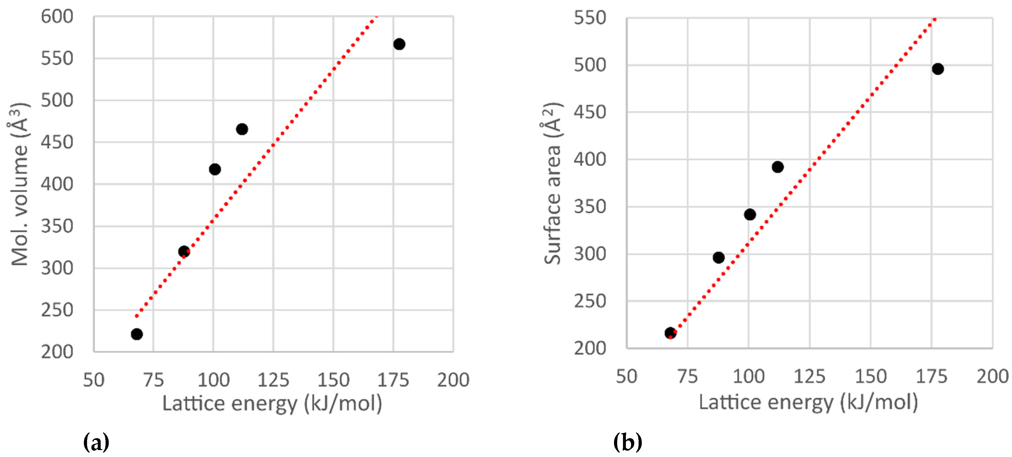
There are no strong intermolecular interactions in the crystal packing of compounds 1–5. The molecules of these compounds are bonded by the H···H and C···H interactions. A dependency analysis between the calculated values of the molecular volume/surface area and the lattice energies indicates that the bonding between the molecules in the crystal of compound 5 is stronger than in the other ones. Conversely, in compounds 3 and 4, the molecules are bonded weaker than it is predicted based on the hypothesis of a linear relationship of these quantities (Figure 1). It should be noted that the lone electron pair is not involved in any noticeable intermolecular interaction in crystals of 3 and 4. On the contrary, in a crystal of compound 5, the authors of [28], based on the analysis of the distribution of deformation electron density, established the interaction between the lone pair of electrons of phosphorus atoms and the phenyl group of the neighboring molecule. The authors of [28] believe that the above-mentioned interaction, along with the mutual steric influence of phenyl groups, is the result of the sp3 hybridization of the phosphorus atoms. In turn, we can assume that it leads to a shrinkage of the crystal packing.
In 2015 the phosphorous and silicon-containing compound (C2F5)3SiCH2P(t-Bu)2 (compound 6) containing a frustrated Lewis pair [30] was synthesized and its crystal structure was determined. The molecule is not involved in any noticeable intermolecular interaction, but the phosphorus atom is tetrahedral. After the addition of CO2 or SO2 to 6, a heteroatomic ring is formed. The silicon atom acquires a distorted trigonal-bipyramidal environment because one of the oxygen atoms of the added molecule is bonded to this silicon. The phosphorus atom becomes bonded to a sulfur or carbon atom. Since compound 6 becomes a zwitterion after a gas is added, the intermolecular interaction energy grows and the temperature of melting goes above the room temperature.
In the crystals of CO2 and SO2 adducts, the C–Si–O angles between the opposite sides of bipyramids are 179.2° and 173.0°, respectively. The lengths of the Si–O bonds are 1.853 and 1.822 Å in the CO2 and SO2 adducts, respectively. The Si–C–P angles are 113.1° (CO2 adduct), 117.1° (SO2 adduct), and 120.4° (compound 6). In all cases, these angles are bigger than the tetrahedral one (109.28°). Probably, the wide Si–C–P angle appears because of the high steric hindrance of silicon and phosphorus atoms, but this angle becomes smaller in adduct crystals because the five-membered ring “pulls together” the silicon and phosphorus atoms.
In the same year, a series of tris(pentafluoroethyl)silicon (TPFES) compounds was studied by Norbert W. Mitzel’s team [31]. The purpose of that work was to search for intermolecular donor–acceptor interactions between the silicon atom and the electron pair of the β-atom in an α-TPFES-substituted compound (oxygen or nitrogen). The authors determined the structure of compounds with –CH2CH3 (7), –CH2OCH3 (8), –CH2N(CH3)2 (9), and –ON(CH3)2 (10) groups. Based on interatomic distances, no interaction of the silicon atom with the β-atom was observed in the first three compounds. However, quantum chemistry calculations and X-ray structure analysis showed that this interaction appeared in the structure of compound 10 (Table 1).
In order to establish whether the Si–N (Si–O) interaction was present, the X-ray diffraction experiment results were compared with the results of quantum chemistry calculations (B3LYP/6-31G(d,p), PBE0/cc–pVTZ, and MP2/cc–pVTZ). According to the authors, only the MP2/cc–pVTZ theory level allows one to approximate the experimental values cc-pVTZ of the Si···N distance for (C2F5)3SiONMe2. The experimentally obtained Si···N distance is smaller by 0.03 Å than that calculated using the MP2 method, and are 0.42 Å and 0.35 Å smaller, respectively, than those calculated by the B3LYP and PBE0 methods. If a methylene group between the silicon and nitrogen atoms existed, no Si-N interaction was found; therefore, the difference between the experiment and calculation was insignificant.
To explain the nature of the Si–N interaction, compound 10 was studied by gas electron diffraction. These molecules are conformationally flexible and the rotation barrier around every single bond is small. To evaluate the conformational flexibility of compound 10 in the gas phase, the experimental radial distribution function of interatomic distances was compared with the distribution of interatomic distances obtained from the calculation by the molecular dynamics method. The R-factors for the radial distribution found by molecular dynamics do not exceed 5.2%. The conformation whose radial distribution function is reproduced most accurately (4.0%) does not contain a short Si···N contact. Thus, this contact is found only in a crystal environment and is probably caused by steric hindrance.
The crystal packing of compounds 7–10 is stabilized mainly due to weak H···F hydrogen bonds and F···F interactions. The F···F interatomic distances of intermolecular interactions are only slightly (by no more than 0.15 Å) shorter than the sum of the corresponding van der Waals radii. The only exception is the structure of compound 10, where the F···F interactions are stronger: some F···F distances are shorter than the sum of the van der Waals radii by more than 0.2 Å. However, the F···F interactions become stronger because of the disordering of one of the pentafluoroethyl groups. This is consistent with the fact that the crystal lattice energy (Table S1 in Supplementary Materials) of compounds 7–9 varies in a very narrow range and is almost independent of the composition.
In 1955, the structure of the low-temperature phase of octamethylcyclotetrasiloxane (compound 11) was established [32]. This compound crystallizes at 17.5 °C and has a phase transition at −16.3 °C [33,34]. The unit cell of the low-temperature phase is tetragonal, belongs to the P42/n space group, and its parameters are a = b = 16.10 ± 0.02 Å, c = 6.47 ± 0.01 Å [32]. The molecules are in the pseudo-chair conformation in the low-temperature phase. For the high-temperature phase, only the space group (I41/n) and the cell parameters were determined. The authors report that the unit cell parameters a and b change insignificantly (± 0.02 Å) during the phase transition, while the parameter c changes from 6.47 Å to 6.83 Å.
In 2018, we published an article about the synthesis of siloxanols [35]. We determined the structure of 1,1,1,3,5,5,5-heptamethyltrisiloxan-2-ol (compound 12) that is viscous at room temperature. It forms a strongly bonded (with O–H···O hydrogen bond) tetramer around the axes in the crystal (Figure 2). The O···O distance in the hydrogen bond is as short as 2.711(4) Å, which means that O–H···O is a strong hydrogen bond.
In 2017, Harald Stueger’s team obtained and studied 2,2,3,3,4,4-hexasilylpentasilane (compound 13) [36]. This compound is a liquid, and the in situ crystallization method was used to determine its crystal structure. The synthetic method is also applicable for the subsequent synthesis of oligomers and polymers with similar structures.
In 2016, Berthold Hoge’s team published a series of works devoted to the synthesis and properties of perfluoroethyl-substituted organogermanium compounds [37,38,39]. In these works, some physicochemical properties of compounds were examined, such as vibrations in the IR spectrum and crystal packing. Four of the eight compounds, namely, (C2F5)2GeBr2 (14), (C2F5)2GeH2 (15), (C2F5)3GeBr (16), and (C2F5)2GePMe3 (17), are liquids at room temperature. In order to determine the structures of their crystalline phases by X-ray diffraction experiment, these samples were crystallized in situ.
A further study of the crystal structures of all four compounds showed that compounds 14 and 16 have similar intermolecular contacts but different packing motives. In the crystal, molecules 14 form stacks in a square packing (Figure 3). The crystals of 15 and 16 form layered structures. The propensity of perfluorinated groups to form layered structures is also shown in [40]. The layers in the crystal of compound 15 are identical and are composed of molecules in an all-trans conformation. The interactions between the layers in the crystal of 16 alternate: half pairs of layers are connected only by F···F contacts, while the other pairs of layers are mainly connected by Br···F interactions (Figure 3, right).
The germanium atom in compound 17 is formally divalent and has a lone electron pair. As a result, the lone electron pair of the germanium atom is involved in the C–H···Ge intermolecular interaction with the methyl group at the phosphorus atom. The C···Ge distance is 3.1793(6) Å, which is shorter than the sum of the van der Waals radii (3.31 Å). The Ge–P bond length is only 2.3989 (16) Å, which is only 0.14 Å longer than the sum of the covalent radii (2.27 Å). Otherwise, the crystal of this compound is not very different from the structure of compound 15: H···F and F···F contacts are also present.
Another interesting result of Hoge’s team was published in the European Journal of Inorganic Chemistry [41]. This work was devoted to the study of various trisubstituted phosphines, di and tri-fluorophosphates. Compounds with acceptor substituents such as pentafluoroethyl, pentafluorophenyl, and tetrafluoropyridyl were prepared.
The most interesting example is a crystal of the compound (C2F5)3PF2 (18), in which the molecules are bonded only via F···F contacts. In this case, the fluorine atoms of the PF2-group are not involved in noticeable intermolecular interactions. The shortest distances F···F involving PF2 groups are 2.995(7) Å (the sum of van der Waals radii equals 3.31 Å).
4. Organosulfur Compounds
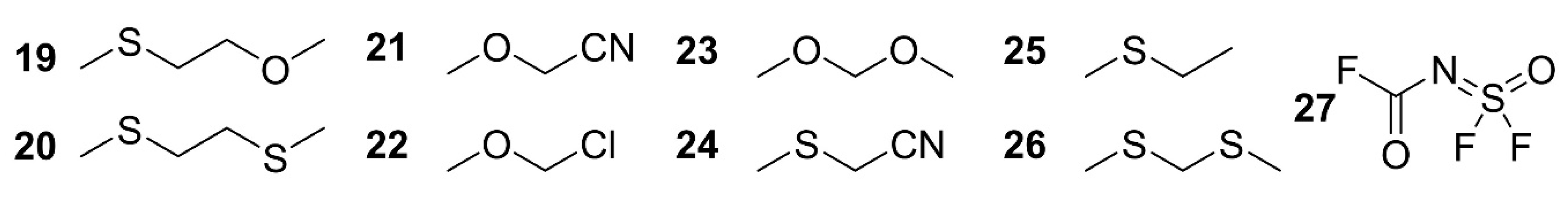
In 1998, Yoshihiro Yokoyama and Yuji Ohashi published an article in which they described the crystal structures of 1-methoxy-2-(methylthio)ethane (MMTE, compound 19) and 1,2-bis(methylthio)ethane (BMTE, compound 20) (Scheme 2) [42]. Crystals of these compounds were grown by in situ crystallization at a temperature of 10 degrees below the melting point. In this case, recrystallization was carried out by the partial melting of a polycrystalline sample. The authors note that the main problem of this method of crystal growth is the chance of accidentally melting the entire sample.
The molecules in the crystals of compounds 19 and 20 are bonded mainly due to the weak dipole–dipole interactions of methyl hydrogen atoms with lone electron pairs of sulfur or oxygen atoms. The crystals belong to the P21/n (for MMTE 19) and P21/c (for BMTE 20) space groups. The authors note that in both crystal packings, the molecules are in almost identical conformations. Indeed, the S–C–C–S and O–C–C–S torsion angles are 180 and 178°, and the C–S–C–C angles are 71 and 79° for compounds 19 and 20, respectively.
To determine the relative stability of possible conformations, quantum chemical calculations were performed. According to these calculations, the SC–CS-trans-conformer is more stable than the gauche-conformer, while the CS–CC-gauche-conformer is more stable than the trans-conformer. Based on the melting points of these compounds and the melting point of 1,2-dimethoxyethane (DME), the authors suggest that the BMTE crystal, which has the highest melting point, is the most stable among them. This was also confirmed by quantum chemical calculations and experiments on crystal growth from binary mixtures of these compounds. Crystals of 20 were grown from the BMTE:MMTE = 1:1 and BMTE:DME = 1:1 mixtures.
In 1999, the same authors [42] published an article where they compared the crystal structures of compounds with general formula XCH2OCH3 (X = CN (21), Cl (22), OCH3 (23)) and XCH2SCH3 (X = CN (24), CH3 (25), OCH3 (26)) [43] obtained by the same method as in [42]. According to the results of quantum-chemical calculations (MP2/6-31G*), the gauche conformation is more favorable than the trans conformation. This is probably due to the presence of a strong anomeric effect. In this case, the gauche conformation realized in the crystal becomes the most beneficial for an isolated molecule.
The difluorosulfenylamide cyanide is a conformationally flexible compound due to the presence of hindered rotation around the formally double S=N bond. To investigate the conformational flexibility of this compound, Cutín and colleagues [44] carried out a gas electron diffraction experiment. Later, Roland Boese et al. [45] used X-ray diffraction with the in situ crystallization method to determine the structure of the related solid-phase compound ((fluoroformyl)imidosulfuryl difluoride, compound 27). It revealed that compound 27 is in the antiperiplanar-synperiplanar conformation. To reveal the relative stability of the possible conformations, quantum chemical calculations (HF/6-31G+*, B3LYP/6-31G+*, B3LYP / 6-311G+*, and MP2/6-311G+*) were performed. The lowest-energy conformation is antiperiplanar-synperiplanar and constitutes 69–80% of the molecules at room temperature (the assessment is based on the Boltzmann distribution). The fraction of the synclinal-synperiplanar conformation is 12–23% of the molecules, while the fraction of the others is small.
5. Organohalogen Compounds
The team of Roland Boese, Ashwini Nangia, and Gautam R. Desiraju described the intermolecular interactions in the crystals of partially fluorinated benzenes 28–34 (Scheme 3) [46]. The subject of the study included mono, ortho, and para-bi-, tri-, tetra-, and penta-fluorobenzenes, and para-halo-substituted fluorobenzenes. Since all these compounds have low-melting points from 225 to 277 K, the in situ crystallization method was used for the crystal growth. An IR laser was used for zone melting.
In a monofluorobenzene 28 crystal, the main type of interatomic interaction is the weak C–H···F hydrogen bond. At the same time, the presence of the C–H···π and F···F interactions was also observed. According to the authors, the presence of these interactions makes the crystal packing of fluorobenzene similar to that in Py·HF, C5H5NO, and PhCN [46]. It is interesting to note that the crystal packings of fluorobenzene and chlorobenzene are significantly different, while the crystals of fluorobenzene and benzonitrile are isostructural (if the fluoro and cyano groups are not taken into account). In the structures of difluorobenzenes, the molecules are packed in layers. The molecules in the layers of ortho-difluorobenzene 29 interact with each other due to weak C–H···F hydrogen bonds and stacking interactions. At the same time, the interaction between the layers is due to the interaction of the lone pairs of fluorine atoms with the π-system of benzene rings (F···π). On the contrary, in a para-difluorobenzene 30 crystal, layers are formed only due to weak hydrogen bonds. No interactions involving the π-system of the benzene ring were observed. In turn, the layers bind to each other through stacking and dipole-dipole interactions of the phenyl rings. The authors note explicit relations between the crystal packing of 1,4-benzoquinone and para-difluorobenzene, which indicates that these molecules have similar electronic structures [46]. Moreover, the crystals of these compounds are isostructural (the cell parameters and space groups coincide).
Similarly, the structures of dihalobenzene crystals are also similar to each other. In all these compounds (except the previously described para-difluorobenzene), pronounced halogen bonds are present (Cl···Cl, Br···Br, F···I, all belonging to the second type [47]) and the orientations of molecules in the layers alternate (Figure 4).
The crystal packing of trifluorobenzene 31 is pseudohexagonal. The authors of [46] draw a clear analogy with the packaging of 1,3,5-triazine [48,49]. In both cases, there is an electrophilic hydrogen atom interacting with two electron pairs of neighboring molecules, which allows one to predict the “hexagonal cell” structure.
The crystal packing of tetra-fluorobenzenes varies greatly. The crystal structure of 1,2,4,5-tetra-fluorobenzene 32 [46] is similar to that of tetrazine [50]. In these structures, molecules in one layer are bonded through dipole-dipole interactions between hydrogen atoms and lone pairs of a neighboring molecule. 1,2,3,4-Tetra-fluorobenzene 33 crystallizes in two polymorphic modifications. The first polymorph was grown at a temperature of 123 K close to the melting point, while the second polymorph was crystallized at a temperature of 195 K from the toluene:pentane system (1:3). Interactions of C–H···F type contribute a lot to the stabilization energy of both polymorphs. In the first polymorph, the molecules form stacking interactions between the layers. In the second one, another motive exists due to the bonding of this type: pairs of molecules are rotated relative to each other by an angle of almost 90° and alternate in a checkerboard pattern. A similar packing is also observed in a pentafluorobenzene crystal. However, dipole–dipole interactions are weaker due to a decrease in the number of hydrogen atoms.
Based on the studies, the authors of [46] concluded that crystalline packing is determined by the presence of acceptor fluorine atoms. The type of packaging depends on the number of these atoms.
Para-dichlorobenzene 33 exists in the form of three polymorphs: α (34a), β (34b), and γ (34c). According to Wheeler and Colson, the number of shortened Cl···Cl contacts (<3.9 Å) increases from three in the β polymorph to four in the α polymorph and five in the γ polymorph, which corresponds to the sequence of phase transition with decreasing temperature [51,52]. A CE–HF/3-21G calculation of the packing energy performed by us predicts that the γ-polymorph is the most stable. In this case, the energies of α and β-polymorphs differ insignificantly (by 1.7 kJ/mol), while the latter is more stable. In 2001, Roland Boese et al. grew crystals of dichlorobenzenes 35 and 36 by the in situ method [53]. To predict the stability of the crystalline structures studied, calculations that included a computer search for the most thermodynamically stable modifications (UNI force field [54]) were performed. The structures generated in the computer search were compared with the results of X-ray diffraction experiments carried out at temperatures of 100 and 220 K for ortho (36) and meta-dichlorobenzenes (35). The parameters of the most thermodynamically stable crystal cells obtained from the calculation are generally consistent with the experimental ones for all the phases. The only exception is the β-polymorph of para-dichlorobenzene (34b), for which the predicted cell parameters differ noticeably from the experimental ones.
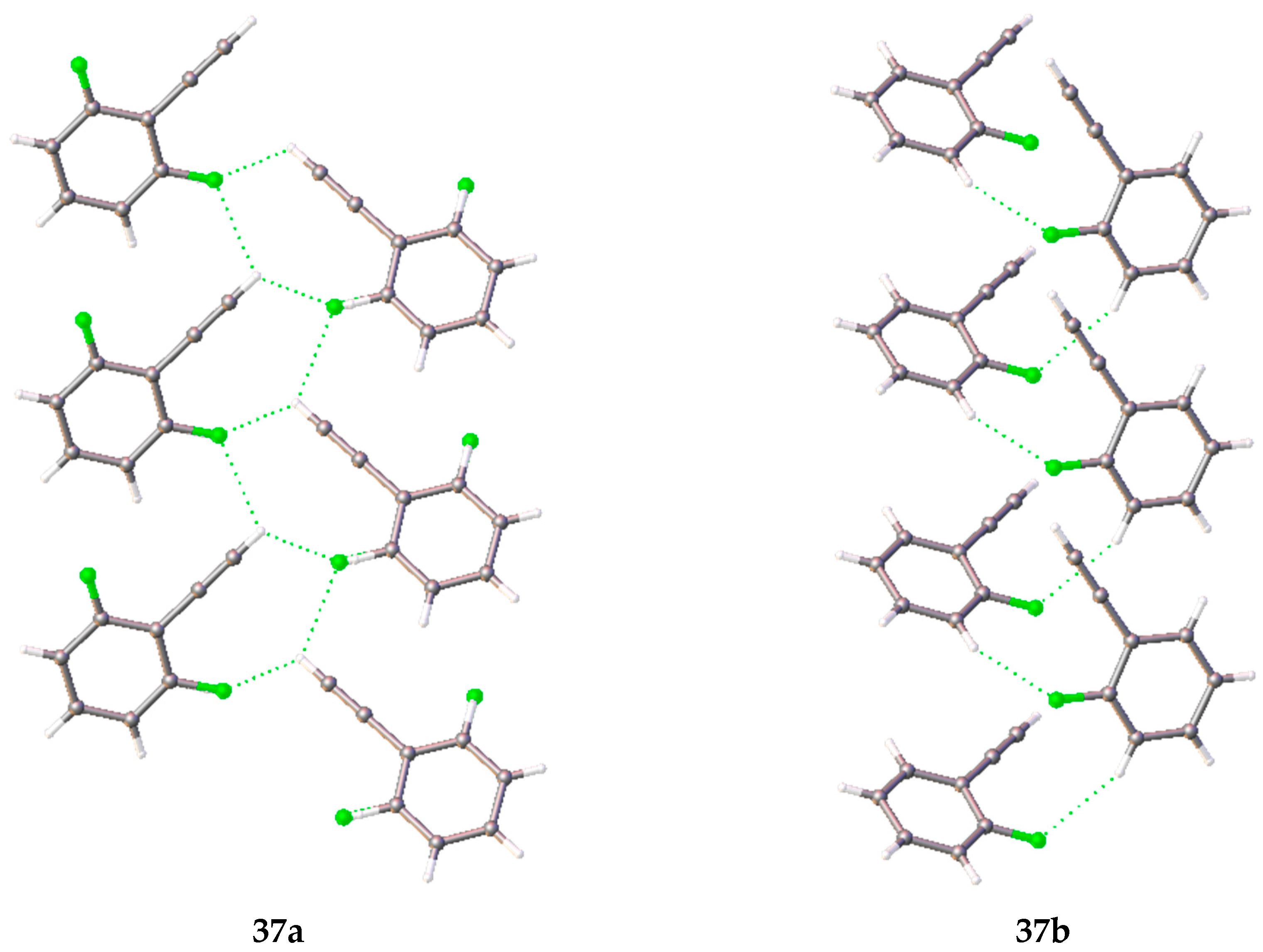
In 2011, Desiraju et al. compared the crystal structures of phenylacetylene and its monofluorinated derivatives [55]. For each of the 2- and 3-fluoro-substituted phenylacetylene derivatives (37 and 38, respectively), the existence of two crystalline phases was determined. The orthorhombic phase 37a (Form 1) crystallizes in the orthorhombic cell (space group Pna21). The molecules in this phase are disordered in such a way that the ratio of the population of fluorine atoms on one or the other side of the acetylene fragment is approximately 1:4. In this phase, there is an interaction of the terminal hydrogen atom of the acetylene fragment with the π-system of the acetylene fragment of the neighboring molecule, and non-classical hydrogen bonds of the C–H···F type. Due to these interactions, a zigzag motif (Figure 5) of molecules along the c axis is present in the crystalline packing. Two types of weak C–H···F hydrogen bonds were found in polymorph 37a: in the first case, the hydrogen atom of the acetylene fragment participates in the bonding, and in the second one, the phenyl ring hydrogen atom interacts with the fluorine atom. Polymorph 37b, which was obtained by slow cooling of a liquid in a capillary, crystallizes in space group P21. In the crystal packing of this polymorph, the interaction of the terminal hydrogen atom of the acetylene fragment with the π-system of the acetylene fragment of the neighboring molecule also exists, but unlike 37a, only the hydrogen atoms of the phenyl fragment participate in the C–H···F weak hydrogen bond.
Both polymorphs of (3-fluorophenyl)acetylene 38 (forms 1 (38a) and 2 (38b)) are monoclinic, but they are characterized by noticeably different cell volumes and different space groups. In fact, 38a crystallizes in the centrosymmetric group P21/n and contains three molecules in the unique part of the cell. The molecules are notable for a hydrogen atom in the phenyl ring which forms the strongest hydrogen bond. It should be noted that the hydrogen atom of the acetylene fragment forms a C–H···F hydrogen bond only in one molecule. In the other two molecules, the same terminal hydrogen atom interacts with the π-system of the acetylene fragment of another molecule. In the 38b crystal, like the 37b crystal, a zigzag-like interaction is present (Figure 6).
(Para-fluorophenyl)acetylene 39 consists of layers in which the molecules are bonded by hydrogen bonds between the terminal acetylene fragment and the fluorine atom of the neighboring molecule in one direction and by stacking in the other direction. The layers are interconnected by weak H···H contacts. As a result, for ortho and meta-substituted monofluorophenylacetylenes, the main motive of crystal packing is the zigzag-like interaction of acetylene fragments, and for para-substituted ones, it is stacking.
It is known that interactions between halogens are usually formed due to the presence of a σ-hole of one atom, which interacts with the electron-saturated “belt” of another atom [56]. Desiraju shows the interactions of cis-trans geometry and L-geometry [47]. The most remarkable examples of compounds that can have crystals with halogen bonds include 4-fluorobenzoyl chloride 40 and 2,3-difluorobenzoyl chloride 41 [57]. The Cl···F interactions in these crystals belong to the second type of geometry (L-geometry). It should be noted that different atoms act as donors and acceptors of a halogen bond. In a crystal of 40a, the fluorine atom is the halogen bond donor and the chlorine atom is the acceptor, while in a crystal of 41, the chlorine atom is the donor and the ortho-fluorine atom is the acceptor. In both crystals, oxygen is involved in the formation of two hydrogen bonds with ortho and meta, or meta and para hydrogens. The second fluorine atom (meta-fluorine) in compound 41 forms a hydrogen bond with the meta hydrogen atom of a neighboring molecule, and in compound 40a a hydrogen bond is formed by an ortho-atom with the single fluorine atom. Thus, the authors concluded that the chlorine atom of the acyl chloride group can act both as a donor and as an acceptor.
Two years later, the same authors published an article in which they described the intermediate phase 40b formed during the crystallization of 40 [58]. The latter crystallized in the same space group and was characterized by a similar layered type of packing. In that work, the authors compared the molecular conformations in crystal phases with the ones calculated for the gas phase. The locations of the molecules within the layers are almost the same for both polymorphs. However, in the intermediate phase, the rings of the molecules form a parquet type packing, while in the previously studied phase 40a, the phenyl rings of the molecules are parallel to the planes of the layers. In addition, the layers are shifted relative to each other. In the layers of both phases, there are significant differences in the length of the Cl···F halogen bond (3.153 Å for the form 40a and 3.283 Å for the form 40b). This is due to the presence of a staircase structure. According to the authors, the crystals of the phase 40b are gradually transformed to phase 40a. Moreover, a crystal can be represented as a combination of domains of both phases during the experiment. Our calculations (Table S1) are in agreement with the conclusion about the instability of 40b (40a is about 5 kJ/mol more favorable than 40b).
Hirshfeld surface analysis (carried out using CrystalExplorer, Version 3.1, [9,59]) was performed by the authors for both crystal structures, and the diagrams of fingerprints of intermolecular interaction were calculated. The main contribution to the Hirschfeld surface corresponds to the C–H···O, C–H···F, and C–H···Cl hydrogen bonds. Nevertheless, the aromatic cycle stacking also makes a significant contribution to the 40b phase surface, while in the stable phase 40a, π–π interactions between the phenyl substituent and the anhydride group are observed instead. The C–C–C–Cl torsion angle between these fragments of the molecule in the 40b phase is as small as 0.4(8)°, while in the crystal of phase 40a it is 11.6(2)°. The deviation from the plane conformation in a crystal of 40a is probably caused by the formation of a stronger F···Cl halogen bond.
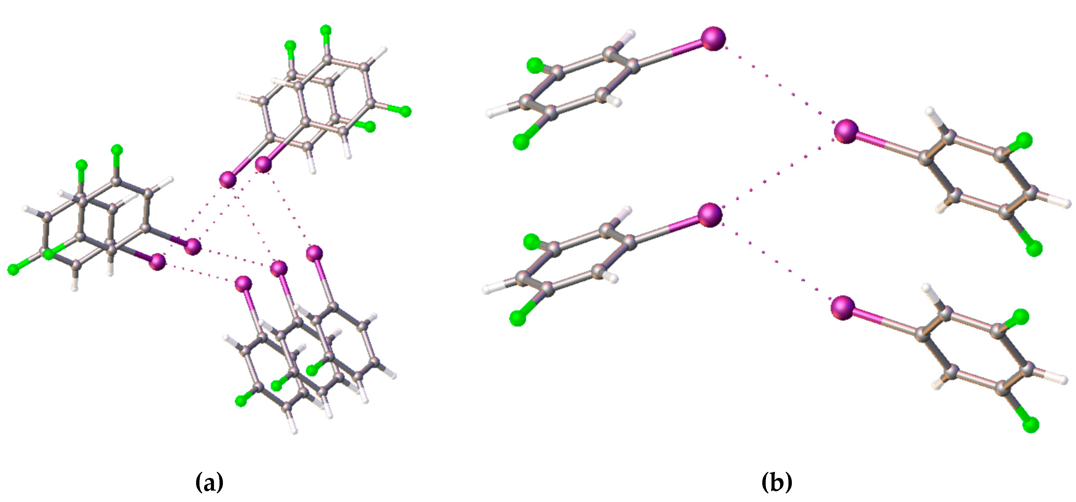
Dikundwar et al. published an article comparing the chloro, bromo, and iodo-derivatives of fluorobenzene [60]. The main goal of that work was to determine the influence of the type of halogen and its position on the formation and geometry of the halogen bond. To determine the crystal structure of the compounds, nine crystals were grown by the in situ method. Two phases were found for meta-chlorofluorobenzene, but only one for each of the remaining compounds. Ortho-chlorofluorobenzene 42 molecules do not form halogen bonds; instead, they participate in the formation of hydrogen bonds and C–H···π interactions. In the first phase of meta-chlorofluorobenzene 43a, the Cl···Cl halogen bonds exist in the L geometry, due to which the molecules form zigzag-like motifs in the crystal packing. In the other phase 43b, halogen bonds are not formed and all intermolecular interactions are related to hydrogen bonds. In a crystal of para-chlorofluorobenzene 44, which was first described by Boese and Desiraju [46] and later studied by Sarah Masters’ team [61], zigzag-like halogen bonds are observed, like in the first phase of meta-chlorofluorobenzene 43a, but they already correspond to the trans-type. Ortho-bromofluorobenzene 45 forms zigzag-like chains in which molecules are bonded by Br···π interactions. In addition, in a 45 crystal, halogen bonds with both fluorine and bromine exist. A meta-bromofluorobenzene 46 crystal contains two independent molecules that form the only trans-type halogen bond (Br···Br). The structure of para-bromofluorobenzene 47 was previously determined by Boese and Desiraju [46]. In a crystal of this compound, it was found that the bromine atoms interact with each other through first-type halogen contacts, while the fluorine atoms participate only in the formation of hydrogen bonds. A similar situation is observed in a crystal of ortho-iodofluorobenzene 48, but, unlike compound 47, the I···I halogen bonds form a zigzag-like motif and belong to the second type. The structure of meta-iodofluorobenzene 49 differs significantly from that described previously. This compound crystallizes in space group P21, with five molecules in the unique part. Three of them are arranged in spirals along the screw pseudo-axis 31 (Figure 7). The molecules around the pseudo-axis form second-type halogen bonds with each other (θ1 ≈ 180°, θ2 ≈ 90°). The remaining two molecules form zigzag-like structures based on halogen contacts, but closer to the first type (θ1 ≈ 155°, θ2 ≈ 124°, Figure 7). The structure of para-iodofluorobenzene 50, also previously studied by the Boese and Desiraju teams [46], contains a zigzag-like structure of the I···I halogen bond, but F···I halogen bonds also exist.
Based on the above, fluorine atoms are more likely to form hydrogen bonds than halogen bonds, while heavier halogens behave in the opposite manner. According to the authors, this is due to the principle of “like likes like”, since the sizes of the fluorine and hydrogen atoms are similar.
In 2015, Nath and Naumov published the structure of a crystal of chlorobenzene 51 [62]. To analyze the intermolecular interactions, the analysis of Hirschfeld partitioning was carried out for chlorobenzene. The calculation showed that a significant fraction of the surface (32.2%) corresponds to the π(C)···H contacts. The H···H and H···Cl contacts contribute 35.1% and 25.9% to the Hirschfeld surface, respectively. Also, in a crystal of chlorobenzene, the zigzag-like motif consisting of molecules bound by a halogen bond exists.
The Pierangelo Metrangolo and Giuseppe Resnati teams determined the crystal structure of a number of co-crystals of amines with halo-pentafluorobenzenes in which a halogen bond is present [63]. This type of intermolecular bond is formed between bromine or iodine atoms in C6F5I or C6F5Br, respectively, and a lone pair of electrons of the nitrogen atom of substituted pyridine or TMEDA. The I···N distances in the compounds studied are 2.784 Å on average, which is shorter than the Br···N distance found (2.882 Å). Nevertheless, all these distances are much shorter than the corresponding sums of the van der Waals radii (3.53 Å for I···N and 3.40 Å for Br···N), which definitely indicates that a halogen bond exists in each of the crystals studied.
In 2014, Klapötke et al. published an article in which they compared the structures of halo-trinitromethanes 52–55 obtained from gas electron diffraction, X-ray diffraction analysis, and quantum chemical calculations [64]. Fluoro and bromo-trinitromethane crystals were grown in situ in a capillary using copper wire as the heating element. According to the authors, contrary to the literature, iodotrinitromethane did not decompose under MoKα radiation, as was stated in [65]. The X-ray diffraction data for chlorotrinitromethane was taken from an earlier article [66]. The results of X-ray diffraction experiments were compared with those from gas electron diffraction. The relative arrangement of nitro groups in the crystal and in the gas phase can be described as a “propeller”. The lengths of C–Hal bonds in a crystal are shorter than in the gas phase, while the opposite pattern is observed for C–N bonds. From the analysis of structural data, it was concluded that a difference in the type of halogen atoms has almost no effect on the C–N bond lengths and N–C–Hal angles in these compounds. On the other hand, the torsion angle of the nitro group has a tendency to increase with an increase in the atomic number of the halogen. As the van der Waals radius of the halogen atoms grows, the intra- and intermolecular interactions between them and the oxygen atoms of the nitro groups increase. According to the authors, intramolecular O···Hal interactions are forced, while intermolecular interactions are advantageous and can be considered as analogs of the L-type halogen bond. Using the NBO, AIM, and IQA methods, the atomic charges, atomic volumes, and interatomic interaction energies were calculated. IQA was performed using the RHF/cc–pVTZ wavefunctions for fluoro and chloro-derivatives and RHF/6-311G(d) for bromo and iodo-derivatives. Both NBO and AIM agree that a negative charge is present on fluorine atom, while it is positive on the other halogens. At the same time, the positive charge on carbon atoms decreases as the halogen atom increases. The charges on nitrogen and oxygen atoms do not depend on the type of halogen at all.
In 2016, Norbert W. Mitzel and Carlos O. Della Védova’s teams published a joint work in which perfluoropropanoic acid fluoride 56 (CF3CF2C(O)F) was described [67]. The structure of this compound was studied by gas electron diffraction, IR, Raman, and ultraviolet spectroscopy, and by quantum chemical calculations (MP2/cc–pVTZ and B3LYP/cc–pVTZ). Compound 56 is a volatile liquid at room temperature, with a melting point of about 146 K. In order to determine the crystal structure, X-ray diffraction analysis and in situ crystallization were used. The crystal was grown at 144 K, after which the sample was slowly cooled to 100 K for the X-ray diffraction experiment. The results showed that all molecules in the crystal are in gauche-conformation, while in the gas phase, according to the results of gas electron diffraction, an equilibrium exists. It was shown that only 85(10)% of molecules are in the gauche-conformation, while the remaining 15(10)% are in the anti-conformation.
6. Intermolecular Interactions in the In Situ Crystallized Compounds
Analysis of crystal packing allowed us to conclude that organoelement compounds described in the present review can be divided into two groups. The first group consists of Si, Ge, P, and S-containing compounds. The heteroatoms in compounds of the first group are surrounded with a shell of hydrocarbon substituents (including perfluorinated ones) and do not participate in any intermolecular interactions. As a consequence, all structure-forming intermolecular interactions are weak classic and non-classic hydrogen bonds (X···H, H···H, C···H; X = Hal, O, N, C). The second group includes organofluorine aromatic compounds where intermolecular interactions between fluorine atoms play a significant role in the stabilization of crystal packing. Moreover, fluorine atoms’ interactions can be of many types—weak hydrogen bonds, halogen bonds, F···F interactions, and F···π interactions [68]. Besides, a noticeable contribution to the stabilization of crystal packing is played by other intermolecular interactions with the participation of the π-systems of phenyl rings [69,70].
According to the calculation of the energy frameworks, compounds 1–17 can be described as loosely packed ones. The ratio between the molecular volume (Å3) and the lattice energy (kJ/mol) in the majority of these compounds is about 3.5-5 Å3·mol/kJ (Table S1). This fact can be explained by the dominance of H···H and C–H···π interactions over others (except for the strong hydrogen bond present in a crystal of 12 compound). The situation is quite different in the case of organosulfur compounds 21–26 where the ratio varies within 2–3. The reason lies in the large contribution of weak C–H···O or C–H···N hydrogen bonds that exceed the contribution from the C···H, H···H, and H···π bonds. Possibly, the correlation between molecular volume and lattice energy can be explained by strong F···F interactions. Organofluorine aromatic compounds have the ratio value close to three due to a contribution from interactions of fluorine and other halogens.
The correlations of the molecular volume/surface area with the lattice energy for all the compounds discussed above are shown in Figure 8. Most of the compounds are liquids at room temperature and have molecular volumes in a range of 120–160 Å3. The Hirshfeld surface areas of the majority of compounds do not exceed 170 Å2. The maximum lattice energy of compounds that are liquid at room temperature is 112 kJ/mol (compound 4). However, most of the compounds have lattice energies between 45 and 65 kJ/mol.
The trend line was calculated on the assumption of a linear relationship between the molecular surface area, volume, and lattice energy values. The R2 values for these trend lines are 0.7451 for plot (a) and 0.7579 for plot (b), respectively (Figure 8). The compounds that are solid at room temperature and the phases that contain strongly disordered molecules were excluded from these relationships.
Several points in Figure 8 lie far from the trend line (the points encircled in red lines). These are compounds 4, 6, 13 (compound 4 is encircled only in part (b)). These compounds stand out because most of the intermolecular interactions in their crystals are weak, but the molecules are still big (the molar volumes are above 400 Å3).
Relatively low R2 values for the trend lines in Figure 8 indicate a poor approximation of the entire data set. In this case, we separated the compounds into three groups. The separation is based on the largest Hirshfeld surface area occupied by the intermolecular interaction of a certain type (Figure 9, Tables S2 and S3). Compounds were separated into “H···H”, “H···Hal” (Hal = F, Cl, Br, I), and “Other” groups.
The first “H···H” group is well approximated linearly (Figure 9a,b). One point (red triangle) was excluded. It corresponds to compound 13. In this crystal, Si–H···H–Si intermolecular contacts are observed instead of C–H···H–C contacts. The Si–H···H–Si interaction is much weaker, and the lattice energy is at least 30 kJ/mol smaller than that predicted by the trend line. The second group “H···Hal” is approximated much worse (Figure 9c,d). Most of the compounds are small molecules. Their Hirshfeld surface area and molecular volume do not exceed 200 Å2/Å3. Three rounded dots correspond to organophosphorus compounds 6, 9, and 17. The last group, “Others”, is well approximated linearly, like the first one (Figure 9e,f).
The dependence of the melting point on the lattice energy is shown in Figure 10. We separated all data into black, blue, and red groups. Black dots correspond to compounds with a molecular surface area below 170 Å2. Blue triangles correspond to compounds whose molecular surface areas are above 170 Å2. The red square corresponds to compound 1. The tangent value (m.p./lattice energy) for the “black” group is between 3.13 and 6.10, and 4.75 on average. The same value for the “blue” group is between 1.63 and 3.12, and 2.41 on average. The molecules of compounds of the “black” group are small and most of them do not form strong intermolecular contacts. On the other hand, in the crystals of the “blue” group compounds, molecular interactions such as halogen bonds or C–H···P hydrogen bonds are present. Compound 1 was assigned to a separate group because the C–H···P bond existing in its crystal is not strong enough, but the Hirshfeld surface area is too large for the “black” group. It means that this compound should be in the “black” group because of its tangent (m.p./lattice energy) value, but it has potentially strong C–H···P interactions.
7. Conclusions
Organoelement compounds, which melt below room temperature, usually have not got any strong intermolecular interactions in their crystals. The significant role in crystal packing is played by medium strength interactions, such as halogen bonds. In this review, the structures of 56 in situ crystallized compounds were discussed. In some crystals, such as 1,1,1,3,5,5,5-heptamethyltrisiloxan-2-ol crystal (compound 12), we see the presence of a strong interaction. Even in these crystals, the weak intermolecular interactions prevail. The physical properties of all in situ crystallized compounds could not be well approximated. But compounds with similar structures have similar interactions in their crystals. So, the compounds were divided into groups by predominant interactions. After the division into groups, the correlation of molecular volume (Å3) and Hirshfeld surface area (Å2) with lattice energy (kJ/mol) became much clearer.
Supplementary Materials
The following are available online at https://www.mdpi.com/2073-4352/10/1/15/s1: Quantum chemistry calculation details, Table S1. Sublimation energies, melting points, molecular volume, and surface area of the compounds, Table S2. Intermolecular interactions in the compounds, Table S3. Intermolecular interactions in halogentrinitromethanes 52–55.
Author Contributions
The sections “In Situ Crystallization: A Retrospective View” and “Organophosphorus, Organosilicon, and Organogermanium Compounds” were written by A.D.V. The section “Organohalogen Compounds” was written by A.F.S. The sections “Introduction” and “Organosulfur compounds” were written by A.A.K. The section “Summary” was written by all the authors. All authors have read and agreed to the published version of the manuscript.
Funding
This work was financially supported by the Russian Science Foundation (project 18-73-00257), the Russian Foundation for Basic Research (project 19-33-90196), and the Ministry of Science and Higher Education of the Russian Federation.
Acknowledgments
The quantum chemistry calculations were performed with the financial support of the Russian Science Foundation (project 18-73-00257). The study of crystal packing was performed with the financial support of the Russian Foundation for Basic Research (project 19-33-90196). The analysis of organofluorine compounds was supported by the Ministry of Science and Higher Education of the Russian Federation.
Conflicts of Interest
The authors declare no conflict of interest.
References
- Davidson, D.W.; Handa, Y.P.; Ratcliffe, C.I.; Tse, J.S.; Powell, B.M. The ability of small molecules to form clathrate hydrates of structure II. Nature 1984, 311, 142–143. [Google Scholar] [CrossRef]
- Kirchner, M.T.; Boese, R.; Billups, W.E.; Norman, L.R. Gas Hydrate Single-Crystal Structure Analyses. J. Am. Chem. Soc. 2004, 126, 9407–9412. [Google Scholar] [CrossRef] [PubMed]
- Kirchner, M.T.; Bläser, D.; Boese, R. Co-crystals with Acetylene: Small Is not Simple! Chem. Eur. J. 2010, 16, 2131–2146. [Google Scholar] [CrossRef] [PubMed]
- Antipin, M.Y. Low-temperature X-ray diffraction analysis: Possibilities in the solution of chemical problems. Russ. Chem. Rev. 1990, 59, 607–626. [Google Scholar] [CrossRef]
- Chopra, D.; Row, T.G. In situ Cryocrystallization: Pathways to study intermolecular interactions. J. Indian Inst. Sci. 2007, 87, 167. [Google Scholar]
- Otálora, F.; Gavira, J.A.; Ng, J.D.; García-Ruiz, J.M. Counterdiffusion methods applied to protein crystallization. Prog. Biophys. Mol. Biol. 2009, 101, 26–37. [Google Scholar] [CrossRef] [PubMed]
- McPherson, A.; Cudney, B. Optimization of crystallization conditions for biological macromolecules. Acta Crystallogr. Sect. F Struct. Biol. Commun. 2014, 70, 1445–1467. [Google Scholar] [CrossRef] [Green Version]
- Fedyanin, I.V.; Smol’yakov, A.F.; Lyssenko, K.A. In situ crystallization of 2,2-dimethoxypropane and dimethyldimethoxysilane: Hunting for Group 14 isomorphism. Mendeleev Commun. 2019, 29, 531–533. [Google Scholar] [CrossRef]
- Jayatilaka, D.; Grimwood, D.J. Tonto: A Fortran Based Object-Oriented System for Quantum Chemistry and Crystallography. In Computational Science—ICCS 2003; Sloot, P.M.A., Abramson, D., Bogdanov, A.V., Gorbachev, Y.E., Dongarra, J.J., Zomaya, A.Y., Eds.; Springer: Berlin/Heidelberg, Germany, 2003; Volume 2660, pp. 142–151. ISBN 978-3-540-40197-1. [Google Scholar]
- Bacon, G.E.; Curry, N.A.; Wilson, S.A.; Spence, R. A crystallographic study of solid benzene by neutron diffraction. Proc. R. Soc. Lond. Ser. Math. Phys. Sci. 1964, 279, 98–110. [Google Scholar]
- Kahn, R.; Fourme, R.; André, D.; Renaud, M. Crystal structure of cyclohexane I and II. Acta Crystallogr. B 1973, 29, 131–138. [Google Scholar] [CrossRef]
- Cox, E.G. The Crystalline Structure of Benzene. Proc. R. Soc. Lond. Ser. Contain. Pap. Math. Phys. Character 1932, 135, 491–498. [Google Scholar] [CrossRef] [Green Version]
- Hassel, O.; Kringstad, H. Tidsskr. Kjemi Og Bergves. 1930, 10, 128–130.
- Lonsdale, K.; Smith, H. LXII. Crystal structure of cyclohexane at −180 °C. Lond. Edinb. Dublin Philos. Mag. J. Sci. 1939, 28, 614–616. [Google Scholar] [CrossRef]
- Price, W.C. The Structure of Diborane. J. Chem. Phys. 1947, 15, 614. [Google Scholar] [CrossRef]
- Price, W.C. The Absorption Spectrum of Diborane. J. Chem. Phys. 1948, 16, 894–902. [Google Scholar] [CrossRef]
- Lipscomb, W.N.; Streib, W.E. Growth, orientation, and X-ray diffraction of single crystals near liquid helium temperatures. Proc. Natl. Acad. Sci. USA 1962, 48, 911–913. [Google Scholar]
- Smith, H.W.; Lipscomb, W.N. Single-Crystal X-Ray Diffraction Study of β-Diborane. J. Chem. Phys. 1965, 43, 1060–1064. [Google Scholar] [CrossRef]
- Jordan, T.H.; Smith, H.W.; Streib, W.E.; Lipscomb, W.N. Single-Crystal X-Ray Diffraction Studies of α-N2 and β-N2. J. Chem. Phys. 1964, 41, 756–759. [Google Scholar] [CrossRef]
- Jordan, T.H.; Streib, W.E.; Smith, H.W.; Lipscomb, W.N. Single-crystal studies of β-F2 and of γ-O2. Acta Crystallogr. 1964, 17, 777–778. [Google Scholar] [CrossRef]
- Trotter, J. The crystal structure of nitrobenzene at −30 °C. Acta Crystallogr. 1959, 12, 884–888. [Google Scholar] [CrossRef]
- Burbank, R.D.; Bensey, F.N. The Structures of the Interhalogen Compounds. I. Chlorine Trifluoride at −120 °C. J. Chem. Phys. 1953, 21, 602–608. [Google Scholar] [CrossRef]
- Eyer, A.; Nitsche, R.; Zimmermann, H. A double-ellipsoid mirror furnace for zone crystallization experiments in spacelab. J. Cryst. Growth 1979, 47, 219–229. [Google Scholar] [CrossRef]
- Brodalla, D.; Mootz, D.; Boese, R.; Osswald, W. Programmed crystal growth on a diffractometer with focused heat radiation. J. Appl. Crystallogr. 1985, 18, 316–319. [Google Scholar] [CrossRef]
- Boese, R.; Antipin, M.Y.; Nussbaumer, M.; Bläser, D. The molecular and crystal structure of 4-methoxybenzylidene-4′-n-butylaniline (MBBA) at −163 °C. Liq. Cryst. 1992, 12, 431–440. [Google Scholar] [CrossRef]
- Boese, R.; Bläser, D.; Nussbaumer, M.; Krygowski, T.M. Low temperature crystal and molecular structure of nitrobenzene. Struct. Chem. 1992, 3, 363–368. [Google Scholar] [CrossRef]
- Boese, R.; Nussbaumer, M. In situ crystallisation techniques. Oxf. Univ. Press 1994, 7, 20. [Google Scholar]
- Bruckmann, J.; Krüger, C. Chelating organophosphines: The use of comparative structural investigations to determine ligand properties. J. Organomet. Chem. 1997, 536–537, 465–472. [Google Scholar] [CrossRef]
- Bruckmann, J.; Krüger, C. Tris(n-butyl)phosphine, Tris(tert-butyl)phosphine and Tris(trimethylsilyl)phosphine. Acta Crystallogr. C 1995, 51, 1152–1155. [Google Scholar] [CrossRef]
- Waerder, B.; Pieper, M.; Körte, L.A.; Kinder, T.A.; Mix, A.; Neumann, B.; Stammler, H.-G.; Mitzel, N.W. A Neutral Silicon/Phosphorus Frustrated Lewis Pair. Angew. Chem. Int. Ed. 2015, 54, 13416–13419. [Google Scholar] [CrossRef]
- Waerder, B.; Steinhauer, S.; Bader, J.; Neumann, B.; Stammler, H.-G.; Vishnevskiy, Y.V.; Hoge, B.; Mitzel, N.W. Pentafluoroethyl-substituted α-silanes: Model compounds for new insights. Dalton Trans. 2015, 44, 13347–13358. [Google Scholar] [CrossRef]
- Steinfink, H.; Post, B.; Fankuchen, I. The crystal structure of octamethyl cyclotetrasiloxane. Acta Crystallogr. 1955, 8, 420–424. [Google Scholar] [CrossRef]
- Patnode, W.; Wilcock, D.F. Methylpolysiloxanes. J. Am. Chem. Soc. 1946, 68, 358–363. [Google Scholar] [CrossRef]
- Hoffman, J.D. Thermal and dielectric study of octamethylcyclotetrasiloxane. J. Am. Chem. Soc. 1953, 75, 6313–6314. [Google Scholar] [CrossRef]
- Arzumanyan, A.V.; Goncharova, I.K.; Novikov, R.A.; Milenin, S.A.; Boldyrev, K.L.; Solyev, P.N.; Tkachev, Y.V.; Volodin, A.D.; Smol’yakov, A.F.; Korlyukov, A.A.; et al. Aerobic Co or Cu/NHPI-catalyzed oxidation of hydride siloxanes: Synthesis of siloxanols. Green Chem. 2018, 20, 1467–1471. [Google Scholar] [CrossRef]
- Haas, M.; Christopoulos, V.; Radebner, J.; Holthausen, M.; Lainer, T.; Schuh, L.; Fitzek, H.; Kothleitner, G.; Torvisco, A.; Fischer, R.; et al. Branched Hydrosilane Oligomers as Ideal Precursors for Liquid-Based Silicon-Film Deposition. Angew. Chem. Int. Ed. 2017, 56, 14071–14074. [Google Scholar] [CrossRef] [PubMed]
- Pelzer, S.; Neumann, B.; Stammler, H.-G.; Ignat’ev, N.; Hoge, B. Synthesis of Bis(pentafluoroethyl)germanes. Chem.—Eur. J. 2016, 22, 4758–4763. [Google Scholar] [CrossRef] [PubMed]
- Pelzer, S.; Neumann, B.; Stammler, H.-G.; Ignat’ev, N.; Hoge, B. Synthesis of Tris(pentafluoroethyl)germanes. Chem.—Eur. J. 2016, 22, 3327–3332. [Google Scholar] [CrossRef]
- Pelzer, S.; Neumann, B.; Stammler, H.-G.; Ignat’ev, N.; Hoge, B. The Bis(pentafluoroethyl)germylene Trimethylphosphane Adduct (C2F5)2 Ge⋅PMe3: Characterization, Ligand Properties, and Reactivity. Angew. Chem. Int. Ed. 2016, 55, 6088–6092. [Google Scholar] [CrossRef]
- Arkhipov, D.E.; Lyubeshkin, A.V.; Volodin, A.D.; Korlyukov, A.A. Molecular Structures Polymorphism the Role of F…F Interactions in Crystal Packing of Fluorinated Tosylates. Crystals 2019, 9, 242. [Google Scholar] [CrossRef] [Green Version]
- Solyntjes, S.; Neumann, B.; Stammler, H.-G.; Ignat’ev, N.; Hoge, B. Difluorotriorganylphosphoranes for the Synthesis of Fluorophosphonium and Bismuthonium Salts. Eur. J. Inorg. Chem. 2016, 2016, 3999–4010. [Google Scholar] [CrossRef]
- Yokoyama, Y.; Ohashi, Y. Crystal and Molecular Structures of RCH2CH2SCH3 (R = OCH3, SCH3). Bull. Chem. Soc. Jpn. 1998, 71, 1565–1571. [Google Scholar] [CrossRef]
- Yokoyama, Y.; Ohashi, Y. Crystal and Molecular Structures of Methoxy and Methylthio Compounds. Bull. Chem. Soc. Jpn. 1999, 72, 2183–2191. [Google Scholar] [CrossRef]
- Cutín, E.H.; Védova, C.O.D.; Mack, H.-G.; Oberhammer, H. Conformation and gas-phase structure of difluorosulphenylimine cyanide, F2S(O)NCN. J. Mol. Struct. 1995, 354, 165–168. [Google Scholar] [CrossRef]
- Boese, R.; Cutin, E.H.; Mews, R.; Robles, N.L.; Della Védova, C.O. ((Fluoroformyl)imido)sulfuryl Difluoride, FC(O)NS(O)F2: Structural, Conformational, and Configurational Properties in the Gaseous and Condensed Phases. Inorg. Chem. 2005, 44, 9660–9666. [Google Scholar] [CrossRef] [PubMed]
- Thalladi, V.R.; Weiss, H.-C.; Bläser, D.; Boese, R.; Nangia, A.; Desiraju, G.R. C−H···F Interactions in the Crystal Structures of Some Fluorobenzenes. J. Am. Chem. Soc. 1998, 120, 8702–8710. [Google Scholar] [CrossRef]
- Desiraju, G.R.; Parthasarathy, R. The nature of halogen···halogen interactions: Are short halogen contacts due to specific attractive forces or due to close packing of nonspherical atoms? J. Am. Chem. Soc. 1989, 111, 8725–8726. [Google Scholar] [CrossRef]
- Wheatley, P.J. The crystal and molecular structure of s-triazine. Acta Crystallogr. 1955, 8, 224–226. [Google Scholar] [CrossRef]
- Coppens, P. Comparative X-Ray and Neutron Diffraction Study of Bonding Effects in s-Triazine. Science 1967, 158, 1577–1579. [Google Scholar] [CrossRef]
- Bertinotti, F.; Giacomello, C.; Liquori, A.M. The structure of heterocyclic compounds containing nitrogen. I. Crystal and molecular structure of s-tetrazine. Acta Crystallogr. 1956, 9, 510–514. [Google Scholar] [CrossRef] [Green Version]
- Wheeler, G.L.; Colson, S.D. Intermolecular interactions in polymorphic p -dichlorobenzene crystals: The α, β, and γ phases at 100 °K. J. Chem. Phys. 1976, 65, 1227–1235. [Google Scholar] [CrossRef]
- Wheeler, G.L.; Colson, S.D. γ-Phase ıt p-dichlorobenzene at 100 K. Acta Crystallogr. Sect. B 1975, 31, 911–913. [Google Scholar] [CrossRef]
- Boese, R.; Kirchner, M.T.; Dunitz, J.D.; Filippini, G.; Gavezzotti, A. Solid-State Behaviour of the Dichlorobenzenes: Actual, Semi-Virtual and Virtual Crystallography. Helv. Chim. Acta 2001, 84, 1561–1577. [Google Scholar] [CrossRef]
- Gavezzotti, A.; Filippini, G. Geometry of the Intermolecular X-H···Y (X, Y = N, O) Hydrogen Bond and the Calibration of Empirical Hydrogen-Bond Potentials. J. Phys. Chem. 1994, 98, 4831–4837. [Google Scholar] [CrossRef]
- Dikundwar, A.G.; Sathishkumar, R.; Guru Row, T.N.; Desiraju, G.R. Structural Variability in the Monofluoroethynylbenzenes Mediated through Interactions Involving “Organic” Fluorine. Cryst. Growth Des. 2011, 11, 3954–3963. [Google Scholar] [CrossRef]
- Murray, J.S.; Paulsen, K.; Politzer, P. Molecular surface electrostatic potentials in the analysis of non-hydrogen-bonding noncovalent interactions. Proc. Indian Acad. Sci. Chem. Sci. 1994, 106, 267–275. [Google Scholar]
- Dikundwar, A.G.; Guru Row, T.N. Evidence for the “Amphoteric” Nature of Fluorine in Halogen Bonds: An Instance of Cl···F Contact. Cryst. Growth Des. 2012, 12, 1713–1716. [Google Scholar] [CrossRef]
- Dikundwar, A.G.; Guru Row, T.N. Tracing a Crystallization Pathway of an RT Liquid, 4-Fluorobenzoyl Chloride: Metastable Polytypic Form as an Intermediate Phase. Cryst. Growth Des. 2014, 14, 4230–4235. [Google Scholar] [CrossRef]
- Wang, H.; Xiao, H.; Liu, N.; Zhang, B.; Shi, Q. Three New Compounds Derived from Nitrofurantoin: X-Ray Structures and Hirshfeld Surface Analyses. Open J. Inorg. Chem. 2015, 5, 63–73. [Google Scholar] [CrossRef] [Green Version]
- Dikundwar, A.G.; Sathishkumar, R.; Guru, R.T.N. Fluorine prefers hydrogen bonds over halogen bonds! Insights from crystal structures of some halofluorobenzenes. Z. Für Krist. Cryst. Mater. 2014, 229, 609–624. [Google Scholar] [CrossRef]
- Masters, S.L.; Mackie, I.D.; Wann, D.A.; Robertson, H.E.; Rankin, D.W.H.; Parsons, S. Unusual asymmetry in halobenzenes, a solid-state, gas-phase and theoretical investigation. Struct. Chem. 2011, 22, 279–285. [Google Scholar] [CrossRef]
- Nath, N.K.; Naumov, P. In situ crystallization and crystal structure determination of chlorobenzene. Maced. J. Chem. Chem. Eng. 2015, 34, 63–66. [Google Scholar] [CrossRef] [Green Version]
- Vasylyeva, V.; Catalano, L.; Nervi, C.; Gobetto, R.; Metrangolo, P.; Resnati, G. Characteristic redshift and intensity enhancement as far-IR fingerprints of the halogen bond involving aromatic donors. CrystEngComm 2016, 18, 2247–2250. [Google Scholar] [CrossRef]
- Klapötke, T.M.; Krumm, B.; Moll, R.; Rest, S.F.; Vishnevskiy, Y.V.; Reuter, C.; Stammler, H.-G.; Mitzel, N.W. Halogenotrinitromethanes: A Combined Study in the Crystalline and Gaseous Phase and Using Quantum Chemical Methods. Chem. Eur. J. 2014, 20, 12962–12973. [Google Scholar] [CrossRef] [PubMed]
- Golovina, N.I.; Atovmyan, L.O. Crystal structure of iodotrinitromethane. J. Struct. Chem. 1967, 7, 230–233. [Google Scholar] [CrossRef]
- Göbel, M.; Tchitchanov, B.H.; Murray, J.S.; Politzer, P.; Klapötke, T.M. Chlorotrinitromethane and its exceptionally short carbon–chlorine bond. Nat. Chem. 2009, 1, 229–235. [Google Scholar] [CrossRef]
- Berrueta Martínez, Y.; Reuter, C.G.; Vishnevskiy, Y.V.; Bava, Y.B.; Picone, A.L.; Romano, R.M.; Stammler, H.-G.; Neumann, B.; Mitzel, N.W.; Della Védova, C.O. Structural Analysis of Perfluoropropanoyl Fluoride in the Gas, Liquid, and Solid Phases. J. Phys. Chem. A 2016, 120, 2420–2430. [Google Scholar] [CrossRef]
- Jelsch, C.; Soudani, S.; Ben Nasr, C. Likelihood of atom–atom contacts in crystal structures of halogenated organic compounds. IUCrJ 2015, 2, 327–340. [Google Scholar] [CrossRef]
- Hunter, C.A. Arene—Arene Interactions: Electrostatic or Charge Transfer? Angew. Chem. Int. Ed. Engl. 1993, 32, 1584–1586. [Google Scholar] [CrossRef]
- Salonen, L.M.; Ellermann, M.; Diederich, F. Aromatic Rings in Chemical and Biological Recognition: Energetics and Structures. Angew. Chem. Int. Ed. 2011, 50, 4808–4842. [Google Scholar] [CrossRef]
Scheme 1.
Organophosphorus, organosilicon, and organogermanium compounds.

Figure 1.
Correlation of molecular volume (Å3) (a) and Hirshfeld surface area (Å2) (b) with lattice energy (kJ/mol) of compounds 1–5. Abscissa axis corresponds to lattice energy, while the ordinate axes correspond to molecular volume and surface area, respectively. Red dotted lines are trend lines.
Figure 1.
Correlation of molecular volume (Å3) (a) and Hirshfeld surface area (Å2) (b) with lattice energy (kJ/mol) of compounds 1–5. Abscissa axis corresponds to lattice energy, while the ordinate axes correspond to molecular volume and surface area, respectively. Red dotted lines are trend lines.

Figure 2.
Tetramer in a 1,1,1,3,5,5,5-heptamethyltrisiloxan-2-ol crystal (compound 12).

Figure 3.
Crystal packing motifs of (C2F5)2GeBr2 (14), (C2F5)2GeH2 (15), and (C2F5)3GeBr (16).

Scheme 2.
Organosulfur and oxygen-containing compounds.

Scheme 3.
Halogen-containing compounds.

Figure 4.
Crystal packing motifs of p-dichlorobenzene 34, p-bromofluorobenzene 47, and p-iodofluorobenzene 50. The halogen bonds close to the L type (θ1 > 155°, θ2 ≈ 90°) are shown as dotted lines.
Figure 4.
Crystal packing motifs of p-dichlorobenzene 34, p-bromofluorobenzene 47, and p-iodofluorobenzene 50. The halogen bonds close to the L type (θ1 > 155°, θ2 ≈ 90°) are shown as dotted lines.

Figure 5.
Crystal packing of (o-fluorophenyl)acetylene 37a and 37b.

Figure 6.
Crystal packing of (m-fluorophenyl)acetylene 38a and 38b.

Figure 7.
Crystal packing motifs in a crystal of meta-fluoroiodobenzene 49: molecules around pseudo-axis 31 (a) and axis 21 (b).
Figure 7.
Crystal packing motifs in a crystal of meta-fluoroiodobenzene 49: molecules around pseudo-axis 31 (a) and axis 21 (b).

Figure 8.
Correlation of molecular volume (Å3) (a) and Hirshfeld surface area (Å2) (b) with lattice energy (kJ/mol) for the majority of compounds (the full list of compounds is shown in Table S2). Red dotted lines are linear trend lines.
Figure 8.
Correlation of molecular volume (Å3) (a) and Hirshfeld surface area (Å2) (b) with lattice energy (kJ/mol) for the majority of compounds (the full list of compounds is shown in Table S2). Red dotted lines are linear trend lines.

Figure 9.
Correlation of molecular volume (Å3) (a,c,e) and Hirshfeld surface area (Å2) (b,d,f) with lattice energy (kJ/mol) for the compounds with predominant H···H interactions (a,b), Hal···H interactions (c,d), and other ones (e,f). Red triangle (a,b) corresponds to 2,2,3,3,4,4-hexasilylpentasilane (compound 13). Three rounded dots (c,d) correspond to organophosphorus compounds 6, 9, and 17. Red dotted lines are linear trend lines.

Figure 10.
The plot of melting point (K) versus lattice energy (kJ/mol). Black dots correspond to compounds with a molecular surface area below 170 Å2. Blue triangles correspond to compounds whose molecular surface area is above 170 Å2. The red square corresponds to compound 1.
Figure 10.
The plot of melting point (K) versus lattice energy (kJ/mol). Black dots correspond to compounds with a molecular surface area below 170 Å2. Blue triangles correspond to compounds whose molecular surface area is above 170 Å2. The red square corresponds to compound 1.


Table 1.
Comparison of experimental XRD data with the theoretical values (bond lengths are in Å, angles are in degrees) of some most important parameters of compounds 7–10 (data from a table in the original source [31]).
Table 1.
Comparison of experimental XRD data with the theoretical values (bond lengths are in Å, angles are in degrees) of some most important parameters of compounds 7–10 (data from a table in the original source [31]).
| Compound | Parameter | XRD | B3LYP | PBE0 | MP2 |
|---|---|---|---|---|---|
| 7 | Si–C–C | 118.6(2) | 116.5 | 117.4 | 116.5 |
| Si⋯C | 2.900(1) | 2.910 | 2.907 | 2.893 | |
| 8 | Si–C–O | 105.4(1) | 106.1 | 107.1 | 104.3 |
| Si⋯O | 2.619(1) | 2.657 | 2.657 | 2.613 | |
| 9 | Si–C–N | 115.5(2) | 112.4 | 116.4 | 111.8 |
| Si⋯N | 2.822(3) | 2.803 | 2.847 | 2.777 | |
| 10 | Si–O–N | 82.0(1)/83.7(1) | 105.0 | 102.6 | 83.6 |
| Si⋯N | 2.060(1)/2.093(1) | 2.494 | 2.425 | 2.107 |
© 2019 by the authors. Licensee MDPI, Basel, Switzerland. This article is an open access article distributed under the terms and conditions of the Creative Commons Attribution (CC BY) license (http://creativecommons.org/licenses/by/4.0/).
Share and Cite
MDPI and ACS Style
Volodin, A.D.; Korlyukov, A.A.; Smol’yakov, A.F. Organoelement Compounds Crystallized In Situ: Weak Intermolecular Interactions and Lattice Energies. Crystals 2020, 10, 15. https://doi.org/10.3390/cryst10010015
AMA Style
Volodin AD, Korlyukov AA, Smol’yakov AF. Organoelement Compounds Crystallized In Situ: Weak Intermolecular Interactions and Lattice Energies. Crystals. 2020; 10(1):15. https://doi.org/10.3390/cryst10010015
Chicago/Turabian StyleVolodin, Alexander D., Alexander A. Korlyukov, and Alexander F. Smol’yakov. 2020. "Organoelement Compounds Crystallized In Situ: Weak Intermolecular Interactions and Lattice Energies" Crystals 10, no. 1: 15. https://doi.org/10.3390/cryst10010015
Note that from the first issue of 2016, this journal uses article numbers instead of page numbers. See further details here.