
In Situ Study on Cu-to-Cu Thermal Compression Bonding
by
 , and
, and
Tongjun Niu
1,
Ke Xu
2,
Chao Shen
2,
Tianyi Sun
2,
Justin Oberst
3,
Carol A. Handwerker
2,
Ganesh Subbarayan
4,
Haiyan Wang
2,5 and
Xinghang Zhang
2,* 1
Center for Integrated Nanotechnologies, Los Alamos National Laboratory, Los Alamos, NM 87545, USA
2
School of Materials Engineering, Purdue University, West Lafayette, IN 47907, USA
3
Lam Research Corporation, Tualatin, OR 97062, USA
4
School of Mechanical Engineering, Purdue University, West Lafayette, IN 47907, USA
5
School of Electrical and Computer Engineering, Purdue University, West Lafayette, IN 47907, USA
*
Author to whom correspondence should be addressed.
Crystals 2023, 13(7), 989; https://doi.org/10.3390/cryst13070989
Submission received: 2 June 2023
/
Revised: 13 June 2023
/
Accepted: 14 June 2023
/
Published: 21 June 2023
(This article belongs to the Section Crystalline Metals and Alloys)
Abstract
:Cu-to-Cu thermal compression bonding (TCB) has emerged as a promising solution for ultrafine pitch packaging in 3D integrated circuit technologies. Despite the progress made by conventional Cu-to-Cu TCB methods in achieving good mechanical strength of the Cu bonds, the bonding processes generally require high temperature and high pressure, which may degrade the performance and reliability of the device. Therefore, it is imperative to investigate the processing parameters to understand the bonding mechanism and achieve effective TCB at a low temperature and low pressure. Here, we developed an in situ TCB technique inside a scanning electron microscope. The in situ TCB method enables a real-time observation of bonding development, which provides critical insights into how the texture and microstructure of Cu bumps may influence the creep and surface diffusion during the bonding process. This work features a strategy to advance our understanding of the bonding mechanisms and provides insight into tailoring the microstructure of Cu for bonding at a low temperature and low pressure.
1. Introduction
Compared to the conventional 2D design, the 3D integrated circuits are recognized for providing increased functionalities in a more compact footprint with lower power dissipation [1,2,3,4]. However, one issue to be addressed for the mass production and application of 3D integrated circuits is to achieve a strong and reliable adhesion between multiple layers of the electronic components [5,6,7]. Cu-to-Cu thermal compression bonding (TCB) has emerged as a promising solution for ultrafine pitch packaging in 3D integrated circuit technologies [8,9,10,11,12,13]. Conventional Cu-to-Cu bonding strategies are capable of achieving Cu bonds with good mechanical strength and electrical properties; the bonding processes generally require high temperature and high pressure that may degrade the performance and reliability of the device [5,7]. Therefore, there is an important need to develop techniques to achieve high-quality Cu bonding with good electrical and mechanical properties at a low temperature and low pressure.
Different strategies have been adopted to accomplish strong and reliable bonding at a low temperature and low pressure. The quality of Cu surfaces is essential in determining the quality of the bonding [10,14,15,16]. Cu can easily oxidize when exposed to ambient oxygen. The formation of native oxide prevents the interdiffusion across the interface, makes it difficult for bonding formation at a low temperature and undermines the quality of the Cu bonds. To remove the oxide layer, Argon ion bombardment treatment has been used to clean and activate the Cu surface [17,18]. This process, known as surface-activated bonding (SAB), can be performed at room temperature and low-stress level but requires an ultrahigh vacuum. The process complexity and potential damage of the underlying active devices due to the high-energy ion bombardment limits the application of the SAB technique [11]. An alternative surface modification method is to introduce a thin layer of passivation agents on top of the Cu surface. Self-assembled monolayer (SAM) formed with linear alkane-thiol atoms is one type of commonly used passivation layer [19,20,21]. SAM is capable of reducing the oxidation layer to pure Cu and preventing future oxidation. Nevertheless, the desorption of SAM requires high-temperature annealing or energetic ion bombardment, which is a major concern for the application of SAM [20]. Metal passivation layers such as Ti, Au and Ni layers have also been widely adopted to prevent oxidation [22,23,24,25,26,27]. The thickness of metal passivation influences the interdiffusion across the layers and needs to be optimized to achieve reliable bonding. Recently, Farisi et al. have demonstrated a novel low-temperature hermetic TCB technique using electroplated Cu sealing frames planarized with fly-cutting [28]. The technique required less surface treatment and achieved a good surface finish, enabling low-temperature bonding development with decent bond strength. A viable alternative to lower bonding temperature and pressure is to utilize (111) textured nanotwinned (NT) Cu. The (111) surfaces are shown to exhibit the highest surface diffusivity among the major crystallographic surfaces [29,30]. Previously, studies have demonstrated promising progress in bonding Cu at a low temperature (<200 °C) and low stress (<5 MPa), with good mechanical strength [10,31].
Several bonding models have been proposed to understand the influence of the diffusion mechanism, the morphology and the microstructure of bonding surfaces on the bonding formation [12,29,32,33,34,35]. These models, though they provided crucial guidelines for choosing appropriate bonding parameters, have not gained sufficient experimental support yet. The in situ micropillar compression test is a technique extensively used to investigate the deformation mechanism of materials at small scales [36,37,38,39,40]. In this paper, we demonstrate a novel in situ TCB method using the micropillar compression technique. The in situ TCB enabled a real-time observation of how the bonding interface evolves under constant stress and pinpointed the onset of several critical stages during bonding formation. The insights from in situ TCB were then combined with the proposed bonding models to discuss the influence of diffusion on bonding development.
2. Materials and Methods
The NT Cu film with a thickness of 10 µm was provided by Lam Research Corporation and was fabricated via electropolishing. A cross-sectional transmission electron microscopy (XTEM) sample of NT Cu was mechanically polished, followed by dimpling and low-energy Ar ion milling with a Gatan PIPS II system. TEM experiments were performed on a FEI Talos 200X microscope operated at 200 kV (Thermo Fisher Scientific, Waltham, MA, USA) The grain size and twin spacing statistics were obtained based on the measurement of 85 grains and 66 twins from the TEM micrograph. The surface roughness was measured using the scanning probe microscopy (SPM) technique by Hysitron TI Premiere Nanoindenter (Bruker, Billerica, MA, USA), equipped with a Berkovich diamond tip.
Micropillars with a double-layer structure for in situ TCB experiments were fabricated using the focused ion beam (FIB) technique using an FEI Quanta 3D FEG dual-beam scanning electron microscope. The bottom pillars with a diameter of ~18 µm and a height of ~5 µm were fabricated with a series of concentric annular trench milling with progressively decreasing ion beam currents on NT Cu film attached to the substrate. The top pillars with a diameter of ~10 µm and a height of ~10 µm were milled out from a free-standing NT Cu film detached from the substrate, as demonstrated in Figure 1b1–b3. The top pillars were then transferred and placed on top of the bottom pillar to assemble the double-layer structure using an Omniprobe manipulator, as shown in Figure 1c1–c3.
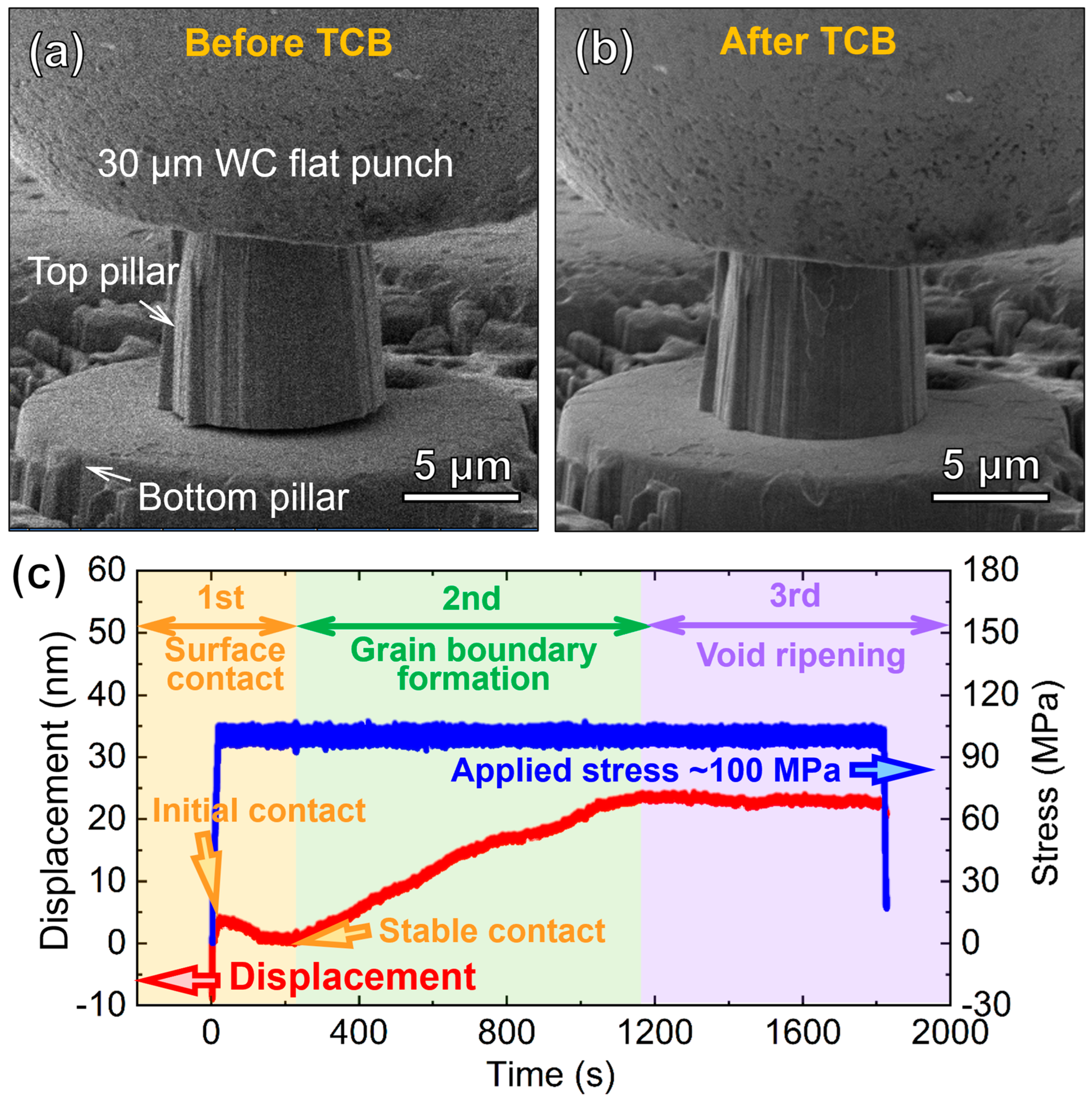
In situ compression tests were carried out inside the FEI Quanta 3D FEG (Thermo Fisher Scientific, Waltham, MA, USA) dual-beam SEM chamber using a Hysitron PI 88 ×R PicoIndenter (Bruker, Billerica, MA, USA). A 30 µm diameter tungsten carbide (WC) flat punch indenter was installed onto a load cell containing a capacitive transducer and a piezoelectric actuator for the uniaxial compression tests at 250 °C. The temperature control was achieved using a probe heater and a stage heater, which heated up simultaneously at a heating rate of 20 °C/min. The details of the in situ high-temperature compression setup can be found in Figure S1 (see in Supplementary Material). The designated temperature was held for 30 min to remove thermal drift. The TCB tests were conducted under load-control mode, and a 100 MPa (~7.85 mN) bonding stress was applied and held for 30 min. Post-bonding analyses on compressed pillars were performed with FIB and scanning electron microscopy (SEM).
3. Results
Figure 2 shows the microstructure of as-deposited NT Cu. The TEM micrograph in Figure 2a was taken from [] zone axis, revealing a high density of growth twins. The twin planes were oriented orthogonally to the film growth direction. The inserted SAD pattern reveals clear evidence of (111) twins as well as a single-crystal-like pattern with distinguished diffraction spots. The high-resolution TEM (HRTEM) micrograph in Figure 2b shows the atomic arrangement of the twin and parent lattice. The statistical distribution in Figure 2c–d reveals an average grain size (D) of 404 nm and an average twin spacing (t) of 69 nm in as-deposited NT Cu film. A 3D topography image is shown in Figure 2e, and the root mean square (RMS) surface roughness was measured to be 5 nm.
In situ TCB test snapshots were shown in Figure 3a–b to compare the geometric evolution of the double-layer pillar before and after TCB under a pressure of 100 MPa at 250 °C for 30 min. Before the TCB test, a small gap existed between the top and bottom pillars, and the gap was eliminated after the TCB test. Figure 3c reveals the evolution of displacement recorded with a piezoelectric actuator and the applied stress as a function of time. The applied stress was held constantly at 100 MPa. The time-dependent displacement gradually increased to ~15 nm following a nearly linear increment rate, indicating the bonding formation across the information. Afterward, the slope became smaller, and the displacement finally reached a plateau at ~20 nm.
To further characterize the bonding interface, a FIB analysis was performed on the compressed pillar. Figure 4a displays the overview of the cross-sectional SEM image of the double-layer pillar after in situ TCB under a pressure of 100 MPa at 250 °C for 30 min. The micrograph clearly reveals the success of bonding development across the interface between the top and bottom pillars. The magnified view in Figure 4b is taken from the orange-dash box in Figure 4a. No obvious in-plane grain growth was observed in both the top and bottom pillars. While the original bonding interface can still be identified, as shown in Figure 4b, no obvious residual voids were detected along the interface.
4. Discussion
The interpretation of the time-dependent displacement evolution from the in situ measurement requires an understanding of the physical mechanism of bonding formation. During the development of Cu diffusion bonding, the evolution of the surface void and bonding interface can be defined by several stages [29,41]. The 1st stage is characterized as the contact of the two surfaces. In general, the surface morphology can be described as sinusoidal curves with periodically spaced hills and valleys. During this stage, the contact preferentially happens at the locations where the peaks of the two wavy surfaces are aligned [7]. Due to the high-stress concentration at these contacted hills, local plastic yielding occurs. It should be noted that no massive atomic diffusion yet occurs during this stage. The displacement evolution shown in Figure 3c indicates the change in the relative spacing between the top and bottom pillars, or more specifically, the distance between the curvature centers of the surface hills of the top pillar and bottom pillar. Therefore, an increment in displacement implies a reduction in the spacing between the two pillars. The initial contact between the two surfaces happened right after ramping up the applied stress to 100 MPa. While the applied stress was held at 100 MPa, a decrease in displacement was observed. Such change is likely to arise from the relaxation of the curved surface of the top pillar. Since the top pillar was fabricated from a free-standing film, the detachment of the free-standing film from the substrate, as well as the ion bombardment during the FIB process, can result in the change in residual stress in the top pillar, leading to a curved surface. According to the plot in Figure 3c, the relaxation and flattening of the curved surface took ~220 s. Afterward, the surface contact became stabilized, which defined the end of the first stage.
During the second stage of bonding formation, the stress gradient along the contacted surface hills drove the mass transport via surface diffusion and grain boundary (GB) diffusion, leading to the expansion of the contact area and the simultaneous reduction in the heights of the surface hills [29,42]. Consequently, the spacing between the top and bottom pillars was reduced, and the displacement was raised further, as shown in Figure 3c. Shie et al. proposed a kinetic theory to estimate the theoretical bonding time () required for completing bonding formation in Cu since the stabilized surface contact is made [29]:
where is the maximum angle between the contact surface normal and the line connecting the point where contact ends to the curvature center of the contact hill and can be assumed to be 1 rad, is the surface roughness, is the effective atomic diffusion distance, is the effective diffusivity, is the Boltzmann constant, is the temperature, is the pressure and is the Cu atomic volume. Equation (1) implies that a higher effective diffusivity, higher bonding pressure and low surface roughness are preferred to promote bonding and shorten the required bonding time. Furthermore, increasing the bonding temperature also accelerates bonding development since diffusivity increases exponentially with increasing temperature. However, to integrate Cu-to-Cu bonding in the 3D IC packaging, a low-temperature and low-pressure bonding process is desired to prevent performance degradation of the device [11]. Strategies to boost effective diffusivity become crucial in achieving well-developed diffusion bonding within a short duration for 3D integration.
One effective method to enhance diffusion and hence promote bonding formation is to tailor the surface orientation of the films [10,43,44]. Previous studies showed that the diffusion coefficient of (111) surfaces of Cu is at least three orders of magnitude higher than that of (100) and (110)-oriented surfaces at the same temperature [10]. For instance, the (111) surface diffusivity of Cu at 250 °C was estimated to be cm2/s, compared to the cm2/s of the (100) surface and cm2/s of the (110) surface [30]. However, it is interesting to note that the (111) textured films tend to form twist-type GBs at the contact points. The GB diffusivity at these twisted GBs could be much lower than that of high-angle-tilt-type GBs, which could limit the bonding development rate [29]. In addition, it is difficult to quantify the combined effect of GB diffusion and surface diffusion. There has been a long debate about whether surface diffusion or GB diffusion governs this stage of bonding development. Previous studies proposed and summarized the bonding mechanism maps as a function of surface roughness and the percentage of bonded area at given temperatures and pressures [41,42]. According to the bonding mechanism maps, when bonding surfaces have a roughness of less than 10 nm, surface diffusion dominates where the fraction of bonded area is relatively low. During this period, the atoms at the contact points are squeezed out to expand the contact area driven by the pressure gradient via surface diffusion. Then, GBs start to form along the contact area, and GB diffusion takes over and governs the bonding formation. As a consequence, the diffusivity in Equation (1) should consider the contribution of both surface diffusion and GB diffusion. A recent study estimated the theoretical bonding time of Cu, assuming only surface diffusion or GB diffusion happened during the second stage, and compared the results with the experimental data under different bonding conditions. It was shown that the estimated bonding time based on surface diffusion was five orders smaller than that based on GB diffusion [29]. Meanwhile, the experimental results of (111) textured NT Cu were close to the surface-diffusion scenario, while the estimated value of randomly oriented Cu was close to the GB diffusion scenario, indicating that the high surface diffusivity of (111) NT Cu can substantially reduce the bonding time.
The third stage of bonding development is categorized as void ripening along the bonding interface. During this stage, the bonding pressure at the contact surface can no longer provide the sufficient driving force for atomic diffusion to fill in the residual voids formed. Instead, the Gibbs–Thompson capillary effect will result in the gradual sealing up of the residual voids dominated by GB diffusion [42,45]. Rebhan et al. proposed a thermodynamic model to estimate the time needed to eliminate the interface voids during TCB of Cu and showed that temperature played a more significant role in determining the void-ripening rate than the applied pressure [35]. Meanwhile, the relative distance between the curvature centers of the surface hills of the top pillar and bottom pillar remains almost unchanged during this stage, and hence the displacement recorded with the piezoelectric actuator stayed constant, as shown in Figure 3c.
5. Conclusions
A novel in situ TCB technique has been developed to examine the bonding formation mechanism in real time. A double-layer pillar architecture was fabricated using NT Cu, and detailed analyses were performed on the time-dependent displacement evolution from the in situ TCB tests. Three distinct bonding stages have been defined based on the dominant driving force and diffusion mechanism for bonding development. The first stage was characterized by the contact of the two surfaces and surface relaxation. During the second stage of bonding formation, the stress gradient along the contacted surface drove the mass transport via surface diffusion and GB diffusion, leading to the expansion of the contact area and GB formation. The displacement curve showed a steady increment during this stage. The third stage of bonding development was categorized as void ripening along the bonding interface, and the displacement reached a plateau with small perturbations. This work offers a new perspective on how the in situ technique can be implemented to advance our understanding of the bonding mechanisms during the Cu TCB process.
Supplementary Materials
The following supporting information can be downloaded at: https://www.mdpi.com/article/10.3390/cryst13070989/s1, Figure S1: In situ high temperature compression set up using the Hysitron PI88 ×R PicoIndenter.
Author Contributions
Conceptualization, T.N. and X.Z.; methodology, T.N., C.S. and T.S.; validation, T.N., K.X. and C.S.; formal analysis, T.N.; investigation, T.N. and T.S.; resources, J.O.; data curation, T.N.; writing—original draft preparation, T.N.; writing—review and editing, T.N. and X.Z.; visualization, T.N.; supervision, C.A.H., G.S. and X.Z.; project administration, C.A.H., H.W. and X.Z.; funding acquisition, X.Z. All authors have read and agreed to the published version of the manuscript.
Funding
This project is primarily funded by Semiconductor Research Corporation (SRC) under Task 2878.017, managed the Center for Heterogeneous Integration Research in Packaging (CHIRP) and SRC.
Data Availability Statement
Data are available upon request.
Acknowledgments
We acknowledge financial support by Semiconductor Research Corporation (SRC) for supporting this work under Task 2878.017, managed by the Center For Heterogeneous Integration Research in Packaging (CHIRP) and SRC. Accesses to Materials Science Microscopy Center at Purdue University and Center for Integrated Nanotechnologies (CINT) are also acknowledged.
Conflicts of Interest
The authors declare no conflict of interest.
References
- Chen, K.-N.; Lee, S.H.; Andry, P.S.; Tsang, C.K.; Topol, A.W.; Lin, Y.-M.; Lu, J.-Q.; Young, A.M.; Ieong, M.; Haensch, W. Structure, design and process control for Cu bonded interconnects in 3D integrated circuits. In Proceedings of the 2006 International Electron Devices Meeting, San Francisco, CA, USA, 11–13 December 2006; pp. 1–4. [Google Scholar]
- Topol, A.W.; La Tulipe, D.C.; Shi, L.; Frank, D.J.; Bernstein, K.; Steen, S.E.; Kumar, A.; Singco, G.U.; Young, A.M.; Guarini, K.W. Three-dimensional integrated circuits. IBM J. Res. Dev. 2006, 50, 491–506. [Google Scholar] [CrossRef]
- Di Cioccio, L.; Radu, I.; Gueguen, P.; Sadaka, M. Direct bonding for wafer level 3D integration. In Proceedings of the 2010 IEEE International Conference on Integrated Circuit Design and Technology, Grenoble, France, 2–4 June 2010; pp. 110–113. [Google Scholar]
- Enquist, P.; Fountain, G.; Petteway, C.; Hollingsworth, A.; Grady, H. Low cost of ownership scalable copper direct bond interconnect 3D IC technology for three dimensional integrated circuit applications. In Proceedings of the 2009 IEEE International Conference on 3D System Integration, San Francisco, CA, USA, 28–30 September 2009; pp. 1–6. [Google Scholar]
- Lu, J.-Q.; Jindal, A.; Kwon, Y.; McMahon, J.J.; Rasco, M.; Augur, R.; Cale, T.S.; Gutmann, R.J. Evaluation procedures for wafer bonding and thinning of interconnect test structures for 3D ICs. In Proceedings of the IEEE 2003 International Interconnect Technology Conference (Cat. No. 03TH8695), Burlingame, CA, USA, 4 June 2003; pp. 74–76. [Google Scholar]
- Niklaus, F.; Kumar, R.J.; McMahon, J.J.; Yu, J.; Lu, J.-Q.; Cale, T.S.; Gutmann, R.J. Adhesive wafer bonding using partially cured benzocyclobutene for three-dimensional integration. J. Electrochem. Soc. 2006, 153, G291. [Google Scholar] [CrossRef]
- Made, R.I.; Gan, C.L.; Yan, L.; Kor, K.H.B.; Chia, H.L.; Pey, K.L.; Thompson, C.V. Experimental characterization and modeling of the mechanical properties of Cu–Cu thermocompression bonds for three-dimensional integrated circuits. Acta Mater. 2012, 60, 578–587. [Google Scholar] [CrossRef]
- Gao, G.; Mirkarimi, L.; Workman, T.; Fountain, G.; Theil, J.; Guevara, G.; Liu, P.; Lee, B.; Mrozek, P.; Huynh, M. Low temperature Cu interconnect with chip to wafer hybrid bonding. In Proceedings of the 2019 IEEE 69th Electronic Components and Technology Conference (ECTC), Las Vegas, NV, USA, 28–31 May 2019; pp. 628–635. [Google Scholar]
- Save, D.; Braud, F.; Torres, J.; Binder, F.; Müller, C.; Weidner, J.O.; Hasse, W. Electromigration resistance of copper interconnects. Microelectron. Eng. 1997, 33, 75–84. [Google Scholar] [CrossRef]
- Liu, C.-M.; Lin, H.-W.; Huang, Y.-S.; Chu, Y.-C.; Chen, C.; Lyu, D.-R.; Chen, K.-N.; Tu, K.-N. Low-temperature direct copper-to-copper bonding enabled by creep on (111) surfaces of nanotwinned Cu. Sci. Rep. 2015, 5, 9734. [Google Scholar] [CrossRef] [Green Version]
- Panigrahy, A.K.; Chen, K.-N. Low temperature Cu–Cu bonding technology in three-dimensional integration: An extensive review. J. Electron. Packag. 2018, 140, 010801. [Google Scholar] [CrossRef] [Green Version]
- Juang, J.-Y.; Lu, C.-L.; Chen, K.-J.; Chen, C.-C.A.; Hsu, P.-N.; Chen, C.; Tu, K.-N. Copper-to-copper direct bonding on highly (111)-oriented nanotwinned copper in no-vacuum ambient. Sci. Rep. 2018, 8, 13910. [Google Scholar] [CrossRef] [Green Version]
- Tan, C.S.; Reif, R. Silicon multilayer stacking based on copper wafer bonding. Electrochem. Solid-State Lett. 2005, 8, G147. [Google Scholar] [CrossRef]
- Park, H.; Kim, S.E. Two-step plasma treatment on copper surface for low-temperature Cu thermo-compression bonding. IEEE Trans. Compon. Packag. Manuf Technol. 2019, 10, 332–338. [Google Scholar] [CrossRef]
- Tseng, C.-H.; Tu, K.-N.; Chen, C. Comparison of oxidation in uni-directionally and randomly oriented Cu films for low temperature Cu-to-Cu direct bonding. Sci. Rep. 2018, 8, 10671. [Google Scholar] [CrossRef] [Green Version]
- Moriceau, H.; Rieutord, F.; Fournel, F.; Di Cioccio, L.; Moulet, C.; Libralesso, L.; Gueguen, P.; Taibi, R.; Deguet, C. Low temperature direct bonding: An attractive technique for heterostructures build-up. Microelectron. Reliab. 2012, 52, 331–341. [Google Scholar] [CrossRef]
- Park, M.; Baek, S.; Kim, S.; Kim, S.E. Argon plasma treatment on Cu surface for Cu bonding in 3D integration and their characteristics. Appl. Surf. Sci. 2015, 324, 168–173. [Google Scholar] [CrossRef]
- Takagi, H.; Kikuchi, K.; Maeda, R.; Chung, T.R.; Suga, T. Surface activated bonding of silicon wafers at room temperature. Appl. Phys. Lett. 1996, 68, 2222–2224. [Google Scholar] [CrossRef]
- Tan, C.S.; Lim, D.F.; Singh, S.G.; Goulet, S.K.; Bergkvist, M. Cu–Cu diffusion bonding enhancement at low temperature by surface passivation using self-assembled monolayer of alkane-thiol. Appl. Phys. Lett. 2009, 95, 192108. [Google Scholar] [CrossRef]
- Ghosh, T.; Krushnamurthy, K.; Panigrahi, A.K.; Dutta, A.; Subrahmanyam, C.; Vanjari, S.R.K.; Singh, S.G. Facile non thermal plasma based desorption of self assembled monolayers for achieving low temperature and low pressure Cu–Cu thermo-compression bonding. RSC Adv. 2015, 5, 103643–103648. [Google Scholar] [CrossRef]
- Tan, C.S.; Lim, D.F.; Ang, X.F.; Wei, J.; Leong, K.C. Low temperature CuCu thermo-compression bonding with temporary passivation of self-assembled monolayer and its bond strength enhancement. Microelectron. Reliab. 2012, 52, 321–324. [Google Scholar] [CrossRef]
- Huang, Y.-P.; Chien, Y.-S.; Tzeng, R.-N.; Shy, M.-S.; Lin, T.-H.; Chen, K.-H.; Chiu, C.-T.; Chiou, J.-C.; Chuang, C.-T.; Hwang, W. Novel Cu-to-Cu Bonding With Ti Passivation at 180 °C in 3-D Integration. IEEE Electron Device Lett. 2013, 34, 1551–1553. [Google Scholar] [CrossRef]
- Chen, H.-Y.; Hsu, S.-Y.; Chen, K.-N. Electrical performance and reliability investigation of cosputtered Cu/Ti bonded interconnects. IEEE Trans. Electron Devices 2013, 60, 3521–3526. [Google Scholar] [CrossRef]
- Panigrahi, A.K.; Bonam, S.; Ghosh, T.; Singh, S.G.; Vanjari, S.R.K. Ultra-thin Ti passivation mediated breakthrough in high quality Cu-Cu bonding at low temperature and pressure. Mater. Lett. 2016, 169, 269–272. [Google Scholar] [CrossRef]
- Bonam, S.; Panigrahi, A.K.; Kumar, C.H.; Vanjari, S.R.K.; Singh, S.G. Interface and reliability analysis of Au-passivated Cu–Cu fine-pitch thermocompression bonding for 3-D IC applications. IEEE Trans. Compon. Packag. Manuf. Technol. 2019, 9, 1227–1234. [Google Scholar] [CrossRef]
- Lin, T.; Li, C.; Si, X.; Li, X.; Yang, B.; Feng, J.; Cao, J. An investigation on diffusion bonding of Cu/Cu using various grain size of Ni interlayers at low temperature. Materialia 2020, 14, 100882. [Google Scholar] [CrossRef]
- Panigrahi, A.K.; Kumar, C.H.; Bonam, S.; Brince, P.K.; Ghosh, T.; Paul, N.; Vanjari, S.R.K.; Singh, S.G. Metal-alloy Cu surface passivation leads to high quality fine-pitch bump-less Cu-Cu bonding for 3D IC and heterogeneous integration applications. In Proceedings of the 2018 IEEE 68th Electronic Components and Technology Conference (ECTC), San Diego, CA, USA, 29 May–1 June 2018; pp. 1561–1566. [Google Scholar]
- Al Farisi, M.S.; Hirano, H.; Tanaka, S. Low-temperature hermetic thermo-compression bonding using electroplated copper sealing frame planarized by fly-cutting for wafer-level MEMS packaging. Sens. Actuators A Phys. 2018, 279, 671–679. [Google Scholar] [CrossRef]
- Shie, K.-C.; Gusak, A.M.; Tu, K.-N.; Chen, C. A kinetic model of copper-to-copper direct bonding under thermal compression. J. Mater. Res. Technol. 2021, 15, 2332–2344. [Google Scholar] [CrossRef]
- Agrawal, P.M.; Rice, B.M.; Thompson, D.L. Predicting trends in rate parameters for self-diffusion on FCC metal surfaces. Surf. Sci. 2002, 515, 21–35. [Google Scholar] [CrossRef]
- Juang, J.-Y.; Lu, C.-L.; Li, Y.-J.; Tu, K.-N.; Chen, C. Correlation between the microstructures of bonding interfaces and the shear strength of Cu-to-Cu joints using (111)-oriented and nanotwinned Cu. Materials 2018, 11, 2368. [Google Scholar] [CrossRef] [Green Version]
- Rebhan, B.; Hingerl, K. Physical mechanisms of copper-copper wafer bonding. J. Appl. Phys. 2015, 118, 135301. [Google Scholar] [CrossRef]
- Fan, A.; Rahman, A.; Reif, R. Copper wafer bonding. Electrochem. Solid-State Lett. 1999, 2, 534. [Google Scholar] [CrossRef]
- Di Cioccio, L.; Gueguen, P.; Taibi, R.; Landru, D.; Gaudin, G.; Chappaz, C.; Rieutord, F.; de Crecy, F.; Radu, I.; Chapelon, L.L. An overview of patterned metal/dielectric surface bonding: Mechanism, alignment and characterization. J. Electrochem. Soc. 2011, 158, P81. [Google Scholar] [CrossRef] [Green Version]
- Rebhan, B.; Svoboda, J.; Panholzer, M. A thermodynamic study of voiding phenomena in Cu–Cu thermo-compression wafer bonding. Microsyst. Technol. 2018, 24, 815–822. [Google Scholar] [CrossRef]
- Sun, T.; Cho, J.; Shang, Z.; Niu, T.; Ding, J.; Wang, J.; Wang, H.; Zhang, X. Deformation mechanism in nanolaminate FeCrAl alloys by in situ micromechanical strain rate jump tests at elevated temperatures. Scr. Mater. 2022, 215, 114698. [Google Scholar] [CrossRef]
- Sun, T.; Shang, Z.; Cho, J.; Ding, J.; Niu, T.; Zhang, Y.; Yang, B.; Xie, D.; Wang, J.; Wang, H. Ultra-fine-grained and gradient FeCrAl alloys with outstanding work hardening capability. Acta Mater. 2021, 215, 117049. [Google Scholar] [CrossRef]
- Zhang, Y.F.; Li, Q.; Xue, S.C.; Ding, J.; Xie, D.Y.; Li, J.; Niu, T.; Wang, H.; Wang, H.; Wang, J. Ultra-strong nanotwinned Al–Ni solid solution alloys with significant plasticity. Nanoscale 2018, 10, 22025–22034. [Google Scholar] [CrossRef] [PubMed]
- Niu, T.; Li, J.; Zhang, Y.; Cho, J.; Ding, J.; Su, R.; Xue, S.; Fan, C.; Shang, Z.; Chen, D.; et al. In-situ studies on the mechanical properties of He ion irradiated nanotwinned Ag. J. Nucl. Mater. 2020, 540, 152392. [Google Scholar] [CrossRef]
- Zhang, Y.F.; Li, Q.; Gong, M.; Xue, S.; Ding, J.; Li, J.; Cho, J.; Niu, T.; Su, R.; Richter, N.A.; et al. Deformation behavior and phase transformation of nanotwinned Al/Ti multilayers. Appl. Surf. Sci. 2020, 527, 146776. [Google Scholar] [CrossRef]
- Chen, K.-N.; Fan, A.; Reif, R. Interfacial morphologies and possible mechanisms of copper wafer bonding. J. Mater. Sci. 2002, 37, 3441–3446. [Google Scholar] [CrossRef]
- Derby, B.; Wallach, E.R. Theoretical model for diffusion bonding. Met. Sci. 1982, 16, 49–56. [Google Scholar] [CrossRef]
- Shie, K.C.; Juang, J.-Y.; Chen, C. Instant Cu-to-Cu direct bonding enabled by <111>-oriented nanotwinned Cu bumps. Jpn. J. Appl. Phys. 2019, 59, SBBA03. [Google Scholar]
- Chang, L.-P.; Wang, J.-J.; Hung, T.-H.; Chen, K.-N.; Ouyang, F.-Y. Direct metal bonding using nanotwinned Ag films with (111) surface orientation under air atmosphere for heterogeneous integration. Appl. Surf. Sci. 2022, 576, 151845. [Google Scholar] [CrossRef]
- Wu, Y.S.; Lai, T.-Y.; Li, M.; Lu, T.-F.; Wang, Y.H.; Tseng, T.Y. Bonding mechanisms of roughened nanotwinned-Cu surface at temperature as low as 120 °C. ECS J. Solid State Sci. Technol. 2020, 9, 124005. [Google Scholar] [CrossRef]
Figure 1.
Demonstration of double-layered Cu pillar fabrication. (a1,a2) Step 1: fabrication of bottom pillar (diameter ~18 µm, height ~5 µm) on the NT Cu film attached to the substrate using focused ion beam (FIB). (a3) Corresponding SEM image showing the fabricated bottom pillar. (b1,b2) Step 2: Preparation of top pillar (diameter ~10 µm, height ~10 µm) using FIB on a free-standing NT Cu film (detached from substrate) and top pillar lift-out using omniprobe. (b3) Corresponding SEM micrograph showing the process of lifting out top pillar using omniprobe. (c1,c2) Step 3: transferring top pillar using omniprobe and aligning and assembling the top and bottom pillars to form the double-layer structure. (c3,c4) Top-down and side views of assembled double-layer pillars.
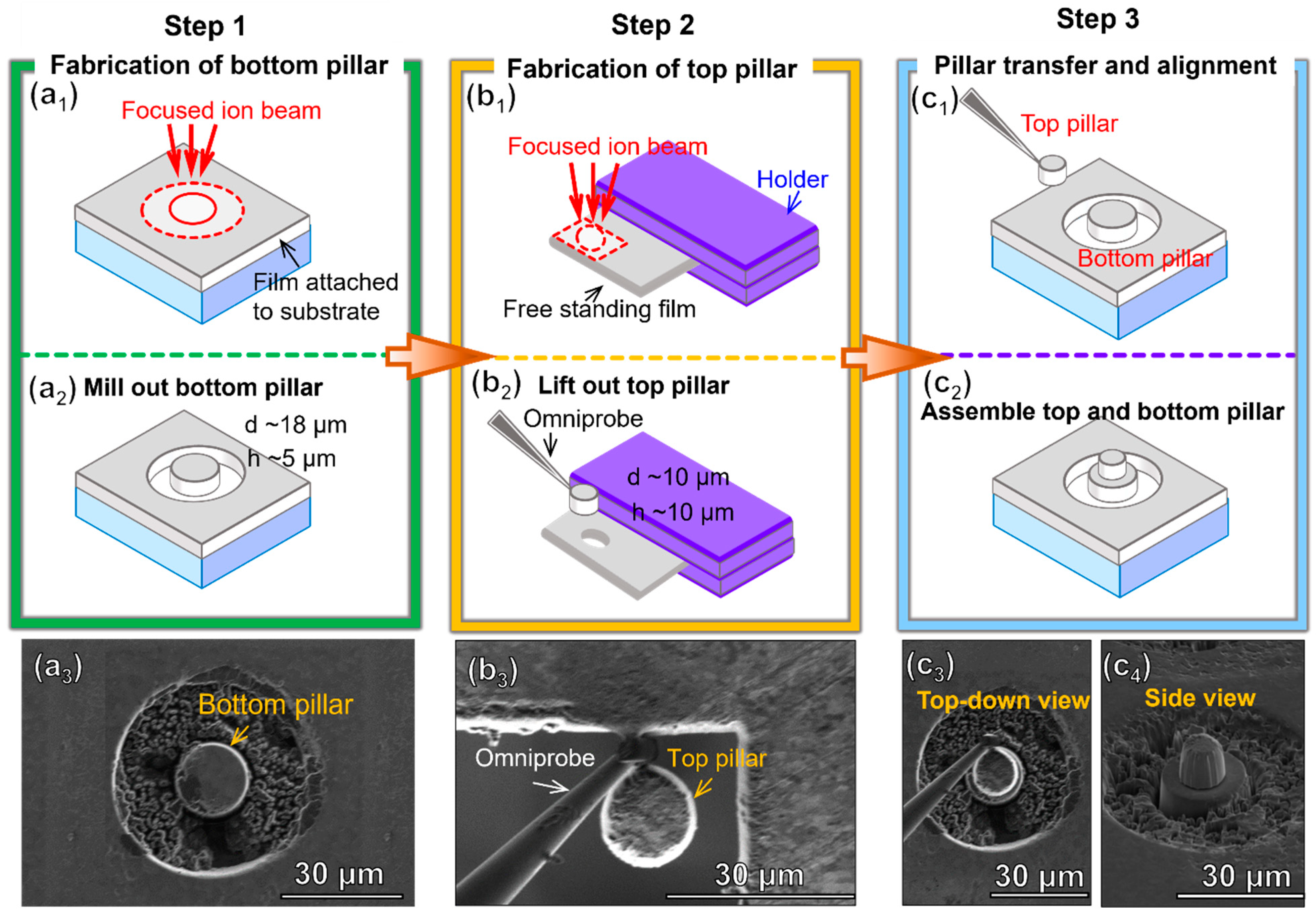
Figure 2.
Microstructure of as-deposited nanotwinned (NT) Cu. (a) Bright-field (BF) TEM micrograph showing a high density of growth twins with inserted selected area diffraction (SAD) pattern. (b) High-resolution TEM (HRTEM) from [] zone axis showing the coherent twin boundary. (c,d) Statistical distribution of grain size and twin spacing of as-deposited NT Cu. The average grain size is 404 nm, and the average twin spacing is 69 nm. (e) 3D topography analysis revealing an RMS surface roughness of approximately 5 nm after chemical mechanical planarization (CMP).
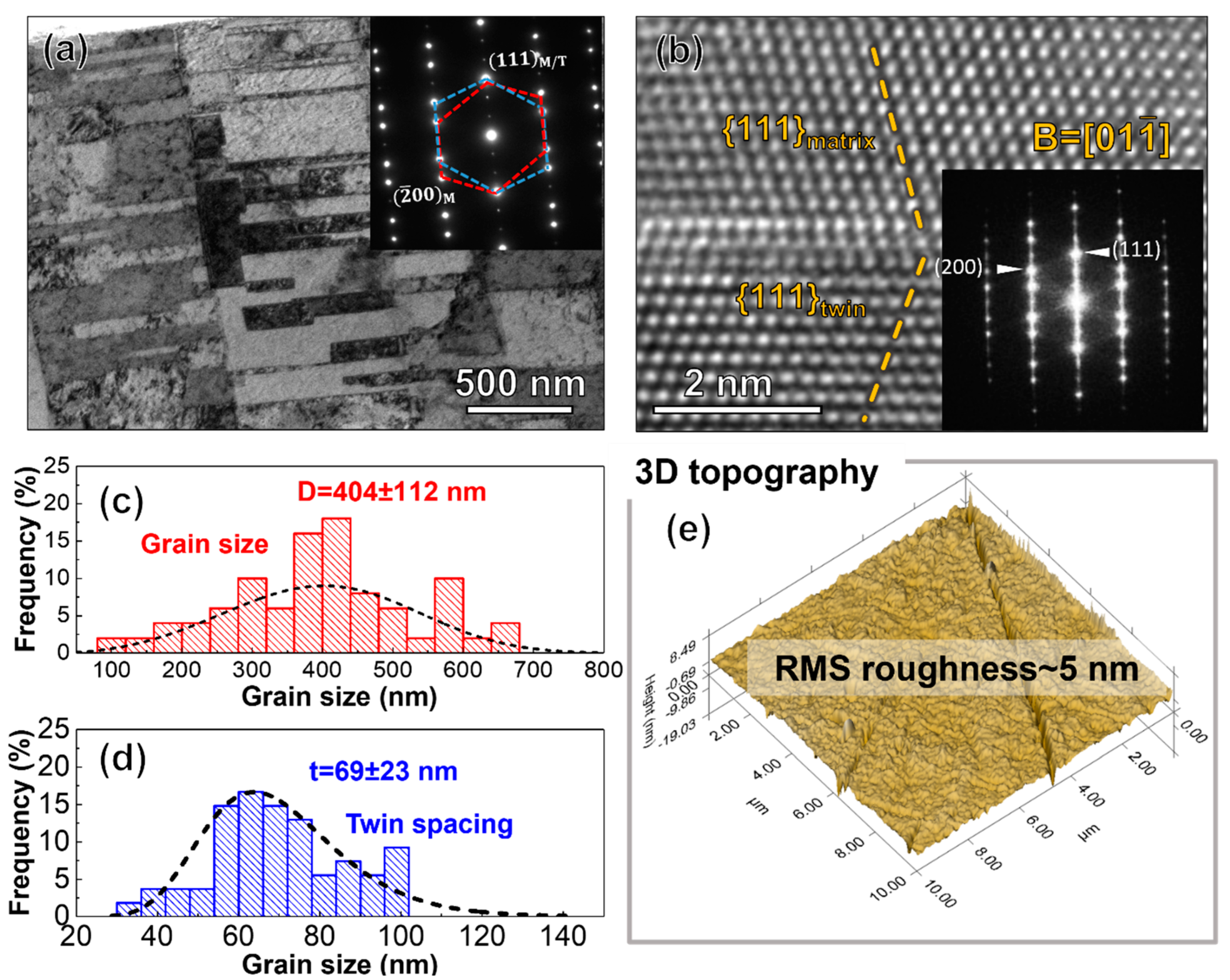
Figure 3.
In situ TCB snapshots showing the double-layer pillar (a) before and (b) after applying a pressure of 100 MPa at 250 °C for 30 min. (c) The evolution of displacement and applied stress as a function of time during in situ TCB.
Figure 3.
In situ TCB snapshots showing the double-layer pillar (a) before and (b) after applying a pressure of 100 MPa at 250 °C for 30 min. (c) The evolution of displacement and applied stress as a function of time during in situ TCB.

Figure 4.
Post-bonding analyses of NT Cu double-layer pillars after TCB. (a) Cross-sectional SEM micrograph showing the overview of bonded double-layer pillar. (b) Magnified SEM image showing the well-bonded interface between top and bottom NT Cu pillars. No residual void was observed along the interface (shown by yellow dash lines), indicating a complete bonding process.

Disclaimer/Publisher’s Note: The statements, opinions and data contained in all publications are solely those of the individual author(s) and contributor(s) and not of MDPI and/or the editor(s). MDPI and/or the editor(s) disclaim responsibility for any injury to people or property resulting from any ideas, methods, instructions or products referred to in the content. |
© 2023 by the authors. Licensee MDPI, Basel, Switzerland. This article is an open access article distributed under the terms and conditions of the Creative Commons Attribution (CC BY) license (https://creativecommons.org/licenses/by/4.0/).
Share and Cite
MDPI and ACS Style
Niu, T.; Xu, K.; Shen, C.; Sun, T.; Oberst, J.; Handwerker, C.A.; Subbarayan, G.; Wang, H.; Zhang, X. In Situ Study on Cu-to-Cu Thermal Compression Bonding. Crystals 2023, 13, 989. https://doi.org/10.3390/cryst13070989
AMA Style
Niu T, Xu K, Shen C, Sun T, Oberst J, Handwerker CA, Subbarayan G, Wang H, Zhang X. In Situ Study on Cu-to-Cu Thermal Compression Bonding. Crystals. 2023; 13(7):989. https://doi.org/10.3390/cryst13070989
Chicago/Turabian StyleNiu, Tongjun, Ke Xu, Chao Shen, Tianyi Sun, Justin Oberst, Carol A. Handwerker, Ganesh Subbarayan, Haiyan Wang, and Xinghang Zhang. 2023. "In Situ Study on Cu-to-Cu Thermal Compression Bonding" Crystals 13, no. 7: 989. https://doi.org/10.3390/cryst13070989
Note that from the first issue of 2016, this journal uses article numbers instead of page numbers. See further details here.