
Dynamic Compression and Constitutive Model in Fe-27Mn-10Al-1C Duplex Lightweight Steel
1
School of Materials Science and Engineering, North University of China, Taiyuan 030051, China
2
Shanxi Key Laboratory of Advanced Metal Materials for Special Environments, Taiyuan 030051, China
3
School of Aerospace Engineering, North University of China, Taiyuan 030051, China
4
School of Materials Science and Engineering, Taiyuan University of Science and Technology, Taiyuan 030024, China
*
Author to whom correspondence should be addressed.
Crystals 2024, 14(2), 178; https://doi.org/10.3390/cryst14020178
Submission received: 16 January 2024
/
Revised: 2 February 2024
/
Accepted: 4 February 2024
/
Published: 10 February 2024
Abstract
:Fe-Mn-Al-C lightweight steels have been of significant interest due to their excellent mechanical properties and unique microstructures. However, there has been limited focus on the dynamic deformation. Here, we systematically investigate the mechanical responses over various strain rates and corresponding microstructure evolution in quasi-static and dynamic compression to reveal the transition of deformation mechanisms. The present lightweight steel exhibits a significant strain rate effect, with the yield strength increasing from 735.8 to 1149.5 MPa when the strain rate increases from 10−3 to 3144 s−1. The deformation in ferrite under high-strain-rate loading is dominated by wave slip, forming a cellular structure (cell block). Meanwhile, the deformation in austenite is dominated by planar slip, forming dislocation substructures such as high-density dislocation walls and microbands. In addition, the deformation twinning (including secondary twinning)- and microband-induced plasticity effects are responsible for the excellent dynamic compression properties. This alloy delays damage location while maintaining high strength, making it ideal for shock loading and high-strain-rate applications. The Johnson–Cook (J–C) constitutive model is used to predict the deformation behavior of lightweight steel under dynamic conditions, and the J–C model agrees well with the experimental results.
1. Introduction
Amidst the current energy and environmental challenges, the automotive industry is imposing more stringent criteria on steel. Fe-Mn-Al-C steel emerges as a promising candidate due to excellent mechanical properties and low density [1,2]. These steels are typically distinguished by a high manganese content (18–30 wt.%), supplemented with additions of aluminum (<12 wt.%) and carbon (0.6–1.8 wt.%) [3]. Significantly, the reduction in density exhibits a direct correlation with the aluminum content, manifesting a 1.5% decrease for every 1 wt.% increase in aluminum [4]. This increase in Al content has been crucial in significantly reducing the overall weight of these steels, in line with the pursuit of lightweight materials in the industry.
The added Al element not only reduces the density, but also improves the stacking fault energy (SFE) [5,6,7,8,9]. Previous results have shown that dislocation splitting is dominant at low SFE conditions (below 50 mJ/m2) and further leads to transformation-induced plasticity (TRIP) effects (<20 mJ/m2) and twinning-induced plasticity (TWIP) effects (20–50 mJ/m2) [7,9]. Moreover, with a continued increased in SFE (>50 mJ/m2), both TRIP and TWIP mechanisms are constrained [10,11], leading to a transition in the deformation mechanism towards dislocation plane slip [12,13]. The SFE not only significantly impacts the deformation mechanism, but also dictates the dislocation slip mode. In conventional face-centered cubic (FCC) metals, the high SFE typically favors the cross-slip of dislocations, resulting in a “wavy slip” mode [14]. However, in lightweight Fe-Mn-Al-C steels characterized by high SFE, the observed slip mode is predominantly planar rather than wavy [13,14,15,16,17,18,19,20]. This apparent contradiction has been explained by researchers, attributing it to the formation of κ-carbides in lightweight steel [13,20]. The presence of these carbides induces a softening effect on the slip plane, thus promoting planar slip. Expanding upon the concept of dislocation slip, various deformation mechanisms have been devised for lightweight steels, including shear-induced plasticity (SIP), microband-induced plasticity (MBIP) [17], and dynamic slip band refinement (DSBR) [18]. All these deformation mechanisms promote the refinement of the microstructure during deformation, which leads to an increase in the strain-hardening rate.
Furthermore, many studies have pointed out that the main deformation mechanisms of FCC alloys are closely related not only to the intrinsic parameters of the material (e.g., SFE), but also to the deformation conditions (e.g., strain, temperature, and strain rate) [21,22,23,24]. In general, as the strain rate increases, the main deformation mechanism changes from dislocation slip to twinning-induced plasticity [7,25]. Consequently, deformation twins will play an increasingly important role, exhibiting high strain-hardening capacity and strain-rate sensitivity (SRS) [23]. Sun et al. investigated the dynamic compressive behavior of the CrMnFeCoNi high-entropy alloy (HEA) at different temperatures and concluded that low temperatures and high strain rates are advantageous for the formation of deformation twins and lead to a high strain-hardening rate of HEA [26]. Liu et al. reported that the simultaneous presence of twins and microbands enhancing the dynamic mechanical properties of NiCoFeCrMoW HEA, attributing this phenomenon to low SFE and Peierls barrier [27]. Based on these results, FCC alloys with low SFE generally exhibit excellent mechanical properties and significant strain-rate sensitivity under dynamic deformation conditions; however, research on FCC alloys with high SFE is limited.
In this study, Fe-27Mn-10Al-1C lightweight steel with FCC matrix and lamellar ferrite was obtained by controlled thermomechanical processing. Subsequent, uniaxial compression experiments were tested on the lightweight steel at strain rates ranging from 10−3 to 3144 s−1. The dynamic deformation behavior of lightweight steels and the associated deformation mechanisms are systematically explored through analysis of mechanical properties and microstructure. The current dynamic plastic deformation behavior of lightweight steel was predicted by the Johnson–Cook (J–C) principal constitutive model.
2. Materials and Experimental Details
Sample Preparation: The nominal composition of the investigated lightweight steel is Fe-27Mn-10Al-1C and it was prepared by vacuum induction melting under a high-purity Ar atmosphere. The final ingot is 150 mm in diameter and 200 mm in height and was homogenised at 1150 °C for 2 h. The actual chemical composition of the measured ingot was determined to be Fe-26.5Mn-10.1Al-0.98C (wt.%, S, P and Si below 0.02%). This was followed by hot rolling at a temperature of 1100 °C to produce 60 mm thick plates. They were then cut into cylinders with a size of 5 × 5 mm for dynamic compression test and 5 × 10 mm for quasi-static compression test, and solution-treated at 1000 °C for 3 min followed by water quenching before compression tests.
Quasi-static compression test: The quasi-static compression test of this lightweight steel was carried out by applying a universal testing machine with a prescribed strain rate of 10−3s−1.
Dynamic compression test: The dynamic compression test was performed using a split Hopkinson pressure bar, schematically shown in Figure 1a. The compression specimen is located between the incidence and transmission bars and is subjected to loading by a high-speed projected impact bar (all bars are made of martensitic aged steel with a diameter of 14.5 mm) with an air pressure of 0.4 and 0.8 MPa. In order to ensure the accuracy and reproducibility of the experiments, at least three experimental samples were tested for each strain rate. Typical waveforms were captured by an oscilloscope as shown in Figure 1b, and the stress–strain curves of dynamic compressive deformation were calculated by the two-wave method [28]. The reflected wave (V) and transmitted wave (V) were measured by strain gauges on the incident and transmitted bars and recorded by an oscilloscope. The stress (MPa), strain, and strain rate (s−1) of the loaded samples could be expressed according to the following equations:
where , , are strain rate, strain, and stress of the specimens, respectively. E and are Young’s modulus of the incident bars and ratio of cross-sectional area of incident bar to specimen. c and l0 are the longitudinal wave velocity of the striker bar material and the height of the specimen, respectively.
Electron backscatter diffraction (EBSD) analysis was performed using a field emission scanning electron microscope (FE-SEM, model: SU5000, Hitachi, Japan). The samples prepared for EBSD testing were initially ground using SiC sandpapers of varying coarseness, namely, 400, 800, 1200, 1500, and 2000 grit, followed by mechanical polishing to eliminate any scratches. Subsequently, the samples were subjected to electrolytic polishing at room temperature for 45 s using a mixed solution of high-chloric acid and ethanol with volume fractions of 10% and 90%, respectively, to achieve a flat analysis surface. EBSD data were analyzed using Orientation Imaging Microscopy (OIM) analysis software provided by Tex-SEM Laboratories, Inc. The microstructure of the samples was characterized using transmission electron microscopy (TEM); the specimens were prepared by ion thinning technique and observed by TEM (model; JEM-2100, Jeol, Japan) with an accelerating voltage of 200 kV. The thin slices used for TEM observation were extracted from the deformed cross-section and subsequently mechanically ground to approximately 40 μm in thickness, followed by ion thinning.
3. Results
3.1. Initial Microstructures
Figure 2a and b show the EBSD phase map and inverse pole figure (IPF) map of lightweight steel after solution treatment. The steel exhibits a dual-phase structure (ferrite + austenite) with lamellar δ-ferrite and fine α-ferrite in matrix consisting of equiaxed grain austenite. The austenite grains are nearly equivalent with 10.1 µm, and the volume fractions of austenite and ferrite phases are estimated to be ~84 and ~16%, respectively. As is well known, single-phase austenitic structures are impossible to obtain during homogenisation or hot rolling due to the high Al content, and coarse ferrite grains are often formed as bands in duplex lightweight steels [29]. As shown in Figure 2c, the local misorientation in the solution-treated sample can be revealed by the kernel-averaged maze (KAM) map. It is observed that the distribution of KAM values is not uniform, which suggests the higher density of geometrically necessary dislocations at grain and phase boundaries than inside the grains.
3.2. Mechanical Response
The current true stress–strain curves for lightweight steel subjected to quasi-static and dynamic compression are shown in Figure 3a. The drop of the curve does not represent sample failure, but rather the end of the Hopkinson pressure bar loading pulse. As is to be expected, the yield strength increases as the strain rate increases. At quasi-static conditions, the yield stress was 735.8 MPa and increased to 1059.3 and 1149.5 MPa at strain rates of 1500 s−1 and 3144 s−1, respectively, indicating that the higher the strain rate, the greater the strain-rate-hardening capacity. This trend is prevalent in HEA, austenitic stainless steels, and high manganese austenitic steels. When a high strain rate (>1000 s−1) is reached, perfect dislocations are pinned down by the phonon drag effect [25,27], so that higher driving stresses need to be applied to induce a large number of local dislocations in the sample.
The strain-hardening rate is the rate of change of true stress as a function of true strain in a material subjected to plastic deformation. The SHR can be defined by Equation (4):
where represents the true stress and is the true strain. Corresponding strain-hardening rate curves are shown in Figure 3b, where two distinct regions are observed at all measured strain rates. In stage I, the pronounced decrease in the SHR signifies the elastic–plastic transition region. Moreover, the strain range of stage I expands with increasing strain rate, which is attributed to the hysteresis slip of dislocations at high strain rates. In stage II (the plastic deformation stage), the SHR of quasi-static compression samples maintains a continuous upward trend, compared to SHR of the dynamic deformation sample with serrated rule. In general, deformation occurs in isothermal conditions under static loading conditions. While under dynamic loading conditions, deformation occurs in adiabatic conditions. A similar phenomenon was observed in TWIP steels and HEA [21,30], suggesting differences in the deformation mechanisms at different strain stages.
3.3. Microstructural Evolution upon Dynamic Compression
In order to understand the origin of the serrated regular SHR of lightweight steels during dynamic deformation, we have investigated the evolution of the deformed structure at different strain rates using TEM techniques, as shown in Figure 4 and Figure 5. At a strain rate of 1500 s−1, rapid dislocation multiplication will be observed in both ferrite and austenite. The microstructure of ferrite shows the wavy dislocation configuration activated by cross-slip, resulting in dislocation tangles (Figure 4a). As shown in Figure 5b, dislocation slip is dominated by planar slip in austenite and forms an array of {111} planar dislocations known as high-density dislocation walls (Figure 4b). There exist dislocation tangles occurring between HDDWs, which are also expected to result in dynamic recovery [31]. At this strain level, deformation twins were activated on {111} slip systems. The TEM bright field image shows a large number of nanotwins in the austenitic grains (Figure 4c), as well as a high density of dislocations accumulated at the twin boundaries. Figure 4d shows the corresponding selective electron diffraction pattern and dark field image, where twin bundles consist of nanotwins with thicknesses of 10–50 nm.
With strain rate increasing to 3144 s−1, some cell blocks (CBs) were formed as a result of extensive cross-slip in ferrite. As previously reported [32,33], these CBs (Figure 5a) were wrapped by dense dislocation walls related to strain localization. This observation suggests that dynamic recovery occurs in ferrite. Figure 5b shows the well-developed microbands that lead to grain subdivision. These microbands are reported to be formed by a high density of dislocation walls parallel to the {111} glide plane [17]. In addition, two different twin systems are activated in austenite at the same strain level. The TEM bright-field image (Figure 5c) and high-resolution TEM image (Figure 5d) clearly show the co-occurrence of primary twins and multiple secondary nanotwins, in which the primary twin extends from the upper right to the lower left and the short secondary twin is tilted. The high density of secondary and primary twins, forming a hierarchical nanotwin network, results from their extensive interactions. It is clear that many primary and secondary twins intersect each other, thus subdividing the matrix into several nanodomains (2–10 nm) (highlighted by orange in Figure 5d), promoting grain refinement.
4. Discussion
4.1. Strain-Rate Sensitivity Effect
Strain-rate sensitivity (SRS, m) is a parameter characterizing the sensitivity of the flow stress to the strain rate during plastic deformation of a metal [34]. It is expressed as
where the is the yield strength and the is the strain rate. The dynamic SRS for the calculation was 0.21.
The SRS of metallic materials is influenced by the type of obstacle hindering dislocation movement. The plastic deformation mechanism is primarily governed by thermally activated dislocation motion, resulting in a typically low SRS (<0.01) [26]. With high-strain-rate conditions, the dislocation activity changes from thermally activated dislocation slip to dislocation drag. Activation of dislocation drag requires transient energy storage [35], which leads to a significant increase in stress. Molecular dynamics simulations conducted by Cao et al. demonstrated the transformation of dislocation nucleation and dislocation drag at high strain rates [36]. In summary, the alteration in dislocation activity contributes to the high SRS and subsequent significant strain-rate-hardening effect.
4.2. Strain-Hardening and -Softening Behavior
In general, the strain hardening of metals and alloys is related to the dislocation multiplication and the obstruction of dislocation motion during plastic deformation [37]. However, the present lightweight steel exhibits complex strain-hardening behavior, in terms of the concurrence of the strain hardening and strain softening. The underlying reason can be attributed to the multiple deformation mechanisms. The following subsection will focus on the effect of these multiple deformation substructures (twinning, MBs, HDDWs, CBs) on the strain-hardening behavior of the present lightweight steel at high strain rates and large strains, i.e., in Stage II.
(I) The effect of dislocation substructure: From the perspective of micro, the essence of plastic deformation in face-centered cubic and body-centered cubic alloys is dislocation slip. The TEM images of the present lightweight steel at strain rates of 1500 s−1 and 3144 s−1 (Figure 4 and Figure 5) reveal that massive dislocation is produced in both austenite and ferrite. As can be seen from Figure 4a, wave slip-dominated ferrite deformation and frequent cross-slip lead to high dislocation multiplication rates through the formation of new Frank–Read sources [38], leading to high work hardening. In addition, a large number of cross-slip dislocations are entangled with each other to form the dense dislocated wall (DDW) [31]. These dislocation structures largely impede the movement of the dislocations, allowing the material to increase in strength and produce strain hardening. In contrast, with planar slip-dominated austenite deformation at strain rates of 1500 s−1, dislocations run in planar sliding bands, leading to dislocation interference and entanglement and the formation of high-density dislocation walls (HDDWs) composed of a high density of dislocations (Figure 4b). These HDDWs typically produce significant long-range back stresses that make it difficult for inter-wall dislocations to be transferred across the wall [30,39], leading to enhanced strain hardening. Similarly, the MBs formed at a strain rate of 3144 s−1 act as barriers for dislocation motion and lead to significant strain hardening. In addition, both HDDWs and MBs contribute to grain refinement, leading to the dynamic Hall–Petch effect [31]. Therefore, the emergence of HDDWs and MBs is the key to conferring work hardening on current lightweight steel.
(II) The effect of deformation nanotwins: Twinning-induced plasticity (TWIP) has been shown to be an essential plastic deformation mechanism in high-manganese steels [7]. Wang et al. reported that deformation twins and the interaction between dislocations and TBs significantly influenced the deformation process of Fe-14.9Mn-1.34Al-0.64C and contributed to the improvement of mechanical properties under dynamic loading [40]. In the present lightweight steel, massive deformation twins (1500 s−1) were observed, thus contributing significantly to the strain-hardening effect. During deformation, the deformation twins created additional boundaries and induced a dynamic Hall–Petch effect, which reduces the dislocation mean free path and increases the dislocation storage capacity. In addition, a large number of nanotwin bundles (Figure 5c) triggered stronger external stresses on the dislocations in the TB, thus sufficiently inhibiting the dislocation annihilation process.
(III) Secondary twinning via detwinning: In our study, a high density of primary nanotwins (PNTs) was observed at the strain rate of 3144 s−1. The PNT spacing ranged from 2 nm to 7 nm, with an average value of 3.5 nm. Under shear stress, the coherent TBs of PNTs disappeared after interacting with the dislocations, which signifies the occurrence of detwinning. The TBs of PNTs can be eliminated through detwinning and then transformed into the high-angle grain boundaries. Secondary twinning is a common phenomenon in pure metals or alloys with low SFE, such as TWIP steels and 304L stainless steels [30]. However, this is not the case in most lightweight steels with high SFE, because of the high energy barrier. This is associated with the emission of partial dislocations from primary twin boundaries and the subsequent extension of inter-grain SF ribbons. According to a previous prediction [41,42,43], the activation of partial dislocations in primary twin boundaries is highly dependent on the boundary spacing. Duan et al. [42] reported that the secondary twins were formed in nanotwin pure nickel micropillars (SFE = 128 mJ/m2) under uniaxial compression tests, due to the fact that critical stress for secondary twinning can be readily reached under a high yield stress level. Similarly, in the studied lightweight steel, the higher flow stress produced in dynamic compression can easily satisfy the critical value for secondary twinning.
(IV) The effect of hierarchical nanotwins: The TEM results also show that a large number of secondary nanotwins were activated in the present lightweight steel at the strain rate of 3144 s−1, which is attributed to the partial release of dislocations on the other side of the twin boundary. It is clear that the observed hierarchical twin substructures are important factors for superior strain hardening. Specifically, in addition to individual DTs, the formation of twin lattices by primary and secondary twins can subdivide the matrix into many nano-scale confined regions, which not only benefits microstructural refinement, but also induces a dynamic Hall–Petch effect [43], leading to significant secondary strain hardening. Moreover, strong interactions are expected to occur within these cross nodes, thus introducing many additional defects that further impart strain hardening.
(V) Strain softening by formation of cellular structures: The strain-hardening curve (Figure 4b) shows that strain softening also occurred during dynamic deformation, which could be attributed to the dynamic recovery induced by dislocation annihilation [30]. Here, the TEM analyses revealed the cross-slip-dominated ferrite deformation, and the frequent cross-slips are usually a prerequisite for cellular structure. During deformation, the formation of CBs in both austenite and ferrite predicts the occurrence of a dynamic recovery. The dislocation tangles between the HDDWs also trigger dynamic recovery in austenite. Zhi et al. suggest that dislocations in this previous dislocation channel not only block dislocation motion, but also annihilate each other with cross-slip dislocations, resulting in a significant dynamic restitution effect [30]. Furthermore, dynamic deformations can usually be considered as adiabatic processes, and considering the high yield strength and large strain of the present lightweight steel under dynamic deformation, the deformation produces significant warming. The adiabatic temperature rise causes the material to deform while dynamic recovery occurs, and this recovery is generated by the combined effect of temperature and external forces. When dynamic restitution occurs, it is easy to produce a large number of cellular substructures, at which time the dislocations are mainly concentrated in the cell walls of the dislocation cells, forming sub-grains (Figure 5a). This process consumes dislocations; thus, the hardening effect is weakened, i.e., dynamic softening occurs.
4.3. Constitutive Models upon Dynamic Compression
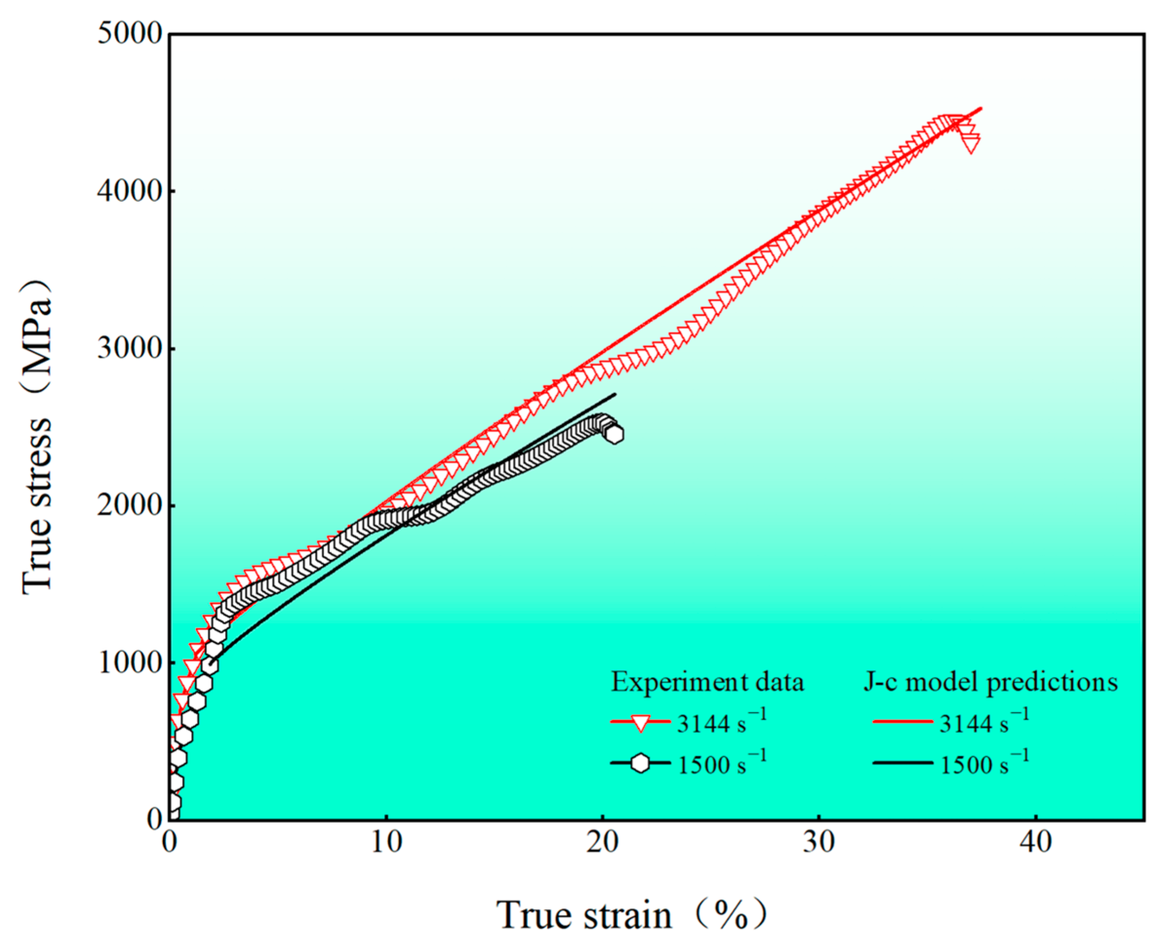
To date, several constitutive models for describing the dynamic response behavior of materials have been suggested [41]. In particular, the Johnson–Cook model can reflect both thermal-softening and strain-hardening effects during processing as well as strain-rate-strengthening effects, and the material parameters are fewer and more readily available, so it is commonly used to describe the strength limits and failure processes of metallic materials under large strains, high strain rates, and high temperatures. Here, the J–C constitutive model under uniaxial compression is written as follows:
where A represents the strain hardening of the material, A is the yield strength of the material under quasi-static condition, B is the strain-strengthening factor, n is the strain-hardening index; reflects the strain-rate strengthening, C is the strain-rate-strengthening factor, and is the strain rate of quasi-static condition (taken as 10−3 s−1); reflects the temperature-softening effect, without considering the effect of adiabatic temperature rise. By fitting the true stress–strain curve (Figure 3a), the parameters of the J–C constitutive equation were obtained A = 735.8, B = 6192.3, n = 0.976, C = 0.18767, and by substituting the parameters into Equation (4), the J–C constitutive equation of the present lightweight steel under dynamic compression can be finally obtained:
By setting the strain rates to 1500 s−1 and 3144 s−1 in Equation (7), the predicted flow stress–strain curves were obtained and are shown in Figure 6 The experimental results agree well with the predictions of the J–C constitutive equation.
5. Conclusions
In the present study, deformation behaviors of lightweight steels upon dynamic compression were investigated. The EBSD and TEM characterizations were employed to investigate the dislocation substructures and nanotwins to uncover micro-mechanisms under dynamic deformation. Several key conclusions can be summarized as follows:
- (1)
- The present lightweight steel exhibits a significant strain rate effect. With the strain rate increasing from 10−3 s−1 to 3144 s−1, the corresponding yield strength increased from 735.8 to 1149.5 MPa. Their dynamic SRS (0.21) is significantly higher than previously reported FCC alloys, which is the main reason for good plasticity under high- strain-rate deformation.
- (2)
- Ferrite microstructure evolution is dominated by wave slip, which forms cellular structures, whereas planar slip dominates in austenite microstructure evolution, forming dislocation substructures such as high-density dislocation walls (HDDWs), microbands, and dislocation cells (CBs).
- (3)
- The present lightweight steels have achieved superior dynamic mechanical properties and extraordinary strain-hardening capacity, which can be attributed to the deformation twins (including secondary twins), dislocation substructures, and their extensive interactions.
- (4)
- The experimental results for dynamic compression are in perfect agreement with the predictions of the Johnson–Cook model, which suggests that the present dynamic-compression deformation process is determined by strain and strain rate.
Author Contributions
P.C.: Investigation, Writing—original draft. D.L.: Supervision, Writing—review and editing. S.B.: Investigation, Writing—review and editing. Y.C.: Writing—review and editing. H.L.: Data accumulation. All authors have read and agreed to the published version of the manuscript.
Funding
This work was financially supported by the National Natural Science Foundation of China (Nos. 52071300, 52375392, 52205402) and the Fundamental Research Program of Shanxi Province (CN) (No. 202203021212318).
Data Availability Statement
Data are contained within the article..
Conflicts of Interest
The authors declare that they have no known competing financial interests or personal relationships that could have appeared to influence the work reported in this paper.
References
- Zhang, W.; Xu, J. Advanced lightweight materials for Automobiles: A review. Mater. Des. 2022, 221, 110994. [Google Scholar] [CrossRef]
- Kim, H.; Suh, D.W.; Kim, N.J. Fe-Al-Mn-C lightweight structural alloys: A review on the microstructures and mechanical properties. Sci. Technol. Adv. Mater. 2013, 14, 014205. [Google Scholar] [CrossRef]
- Chen, S.P.; Rana, R.; Haldar, A.; Ray, R.K. Current state of Fe-Mn-Al-C low density steels. Prog. Mater. Sci. 2017, 89, 345–391. [Google Scholar] [CrossRef]
- Zambrano, O.A. A general perspective of Fe-Mn-Al-C steels. J. Mater. Sci. 2018, 53, 14003–14062. [Google Scholar] [CrossRef]
- Bai, S.B.; Chen, Y.A.; Liu, X.; Lu, H.H.; Bai, P.K.; Li, D.Z.; Huang, Z.Q.; Li, J.Y. Research status and development prospect of Fe-Mn-C-Al system low-density steels. J. Mater. Res. Technol. 2023, 25, 1537–1559. [Google Scholar] [CrossRef]
- Shih, M.; Miao, J.; Mills, M.; Ghazisaeidi, M. Stacking fault energy in concentrated alloys. Nat. Commun. 2021, 12, 3590. [Google Scholar] [CrossRef]
- Mahajan, S.; Chin, G.Y. Formation of deformation twins in f.c.c. crystals. Acta Metall. 1973, 21, 1353–1363. [Google Scholar] [CrossRef]
- Pierce, D.T.; Jiménez, J.A.; Bentley, J.; Raabe, D.; Wittig, J.E. The influence of stacking fault energy on the microstructural and strain hardening evolution of Fe-Mn-Al-Si steels during tensile deformation. Acta Mater. 2015, 100, 178–190. [Google Scholar] [CrossRef]
- Bai, S.B.; Li, D.Z.; Lu, H.H.; Niu, W.Q.; Liang, W.; Bai, P.K.; Huang, Z.Q. Enhancing strength and ductility combination via tailoring the dislocation density in medium Mn steel. Mater. Sci. Eng. A 2023, 879, 145227. [Google Scholar] [CrossRef]
- Chen, P.; Chen, R.; Li, X.W. Tensile deformation behavior related with strain-induced martensitic transformation in a duplex Fe-Mn-Al-C low-density steel. Mater. Charact. 2022, 189, 111954. [Google Scholar] [CrossRef]
- You, R.K.; Kao, P.W.; Gan, D. Mechanical properties of Fe-30Mn-10Al-1C-1Si alloy. Mater. Sci. Eng. A 1989, 117, 141–148. [Google Scholar] [CrossRef]
- Huang, H.; Gan, D.; Kao, P.W. Effect of alloying additions on the κ phase precipitation in austenitic Fe-Mn-Al-C alloys. Scr. Metall. Mater. 1994, 30, 499–504. [Google Scholar] [CrossRef]
- Haase, C.; Zehnder, C.; Ingendahl, T.; Bikar, A.; Tang, F.; Hallstedt, B.; Hu, W.P.; Bleck, W.; Molodov, D.A. On the deformation behavior of κ-carbide-free and κ-carbide-containing high-Mn light-weight steel. Acta Mater. 2017, 122, 332–343. [Google Scholar] [CrossRef]
- Frommeyer, G.; Brüx, U. Microstructures and mechanical properties of high-strength Fe-Mn-Al-C light-weight TRIPLEX steels. Steel Res. Int. 2006, 77, 627–633. [Google Scholar] [CrossRef]
- Li, M.C.; Chang, H.; Kao, P.W.; Gan, D. The effect of Mn and Al contents on the solvus of κ phase in austenitic Fe-Mn-Al-C alloys. Mater. Chem. Phys. 1999, 59, 96–99. [Google Scholar] [CrossRef]
- Hong, S.I.; Laird, C. Mechanisms of slip mode modification in F.C.C. solid solutions. Acta Metall. Mater. 1990, 38, 1581–1594. [Google Scholar] [CrossRef]
- Yoo, J.D.; Park, K.T. Microband-induced plasticity in a high Mn-Al-C light steel. Mater. Sci. Eng. A 2008, 496, 417–424. [Google Scholar] [CrossRef]
- Welsch, E.; Ponge, D.; Haghighat, S.M.H.; Sandlöbes, S.; Choi, P.; Herbig, M.; Zaefferer, S.; Raabe, D. Strain hardening by dynamic slip band refinement in a high-Mn lightweight steel. Acta Mater. 2016, 116, 188–199. [Google Scholar] [CrossRef]
- Yoo, J.D.; Hwang, S.W.; Park, K.T. Origin of Extended Tensile Ductility of a Fe-28Mn-10Al-1C Steel. Metall. Mater. Trans. A 2009, 40, 1520–1523. [Google Scholar] [CrossRef]
- Liu, C.Y.; Shen, S.C.; Xie, P.; Wu, C.L. Deformation behaviors of a Fe-20Mn-3Al-3Si TRIP steel under quasi-static compression and dynamic impact. Mater. Charact. 2022, 191, 112095. [Google Scholar] [CrossRef]
- Xiong, Z.P.; Ren, X.P.; Bao, W.P.; Li, S.X.; Qu, H.T. Dynamic mechanical properties of the Fe-30Mn-3Si-4Al TWIP steel after different heat treatments. Mater. Sci. Eng. A 2011, 530, 426–431. [Google Scholar] [CrossRef]
- Zhang, D.D.; Zhang, J.Y.; Kuang, J.; Liu, G.; Sin, J. Superior strength-ductility synergy and strain hardenability of Al/Ta co-doped NiCoCr twinned medium entropy alloy for cryogenic applications. Acta Mater. 2021, 220, 117288. [Google Scholar] [CrossRef]
- Gray, G.T. High-Strain-Rate Deformation: Mechanical Behavior and Deformation Substructures Induced. Annu. Rev. Mater. Res. 2012, 42, 285–303. [Google Scholar] [CrossRef]
- Wang, Y.Z.; Jiao, Z.M.; Bian, G.B.; Yang, H.J.; He, H.W.; Wang, Z.H.; Liaw, P.K.; Qiao, J.W. Dynamic tension and constitutive model in Fe40 Mn20 Cr20 Ni20 high-entropy alloys with a heterogeneous structure. Mater. Sci. Eng. A 2022, 839, 124837. [Google Scholar] [CrossRef]
- Foley, D.L.; Huang, S.H.; Anber, E.; Shanahan, L.; Shen, Y.; Lang, A.C.; Barr, C.M.; Spearot, D.; Lamberson, L.; Taheri, M.L. Simultaneous twinning and microband formation under dynamic compression in a high entropy alloy with a complex energetic landscape. Acta Mater. 2020, 200, 1–11. [Google Scholar] [CrossRef]
- Sun, J.; Zhao, W.X.; Yan, P.; Xia, X.Z.; Jiao, L.; Wang, X.B. Effect of temperature and strain rate on quasi-static and dynamic compressive behavior of forged CrMnFeCoNi high entropy alloy. Mater. Sci. Eng. A 2023, 870, 144846. [Google Scholar] [CrossRef]
- Liu, X.L.; Wu, Y.D.; Wang, Y.S.; Chen, J.B.; Bai, R.; Gao, L.; Xu, Z.; Wang, W.Y.; Tan, C.W.; Hui, X.D. Enhanced dynamic deformability and strengthening effect via twinning and microbanding in high density NiCoFeCrMoW high-entropy alloys. J. Mater. Sci. Technol. 2022, 127, 164–176. [Google Scholar] [CrossRef]
- Davies, E.D.H.; Hunter, S.C. The dynamic compression testing of solids by the method of the split Hopkinson pressure bar. J. Mech. Phys. Solids 1963, 11, 155–179. [Google Scholar] [CrossRef]
- Song, H.J.; Yoo, J.S.; Sohn, S.S.; Koo, M.; Lee, S. Achievement of high yield strength and strain hardening rate by forming fine ferrite and dislocation substructures in duplex lightweight steel. Mater. Sci. Eng. A 2017, 704, 287–291. [Google Scholar] [CrossRef]
- Wei, Y.; Li, Y.Q.; Zhu, L.C.; Liu, Y.; Lei, X.Q.; Wang, G.; Wu, Y.X.; Liu, J.B.; Wang, H.T.; Gao, H.J. Evading the strength–ductility trade-off dilemma in steel through gradient hierarchical nanotwins. Nat. Commun. 2014, 5, 3580. [Google Scholar] [CrossRef]
- Zhi, H.H.; Li, J.S.; Li, W.M.; Elkot, M.; Antonov, S.; Zhang, H.; Lai, M.J. Simultaneously enhancing strength-ductility synergy and strain hardenability via Si-alloying in medium-Al FeMnAlC lightweight steels. Acta Mater. 2023, 245, 118611. [Google Scholar] [CrossRef]
- Wang, Z.W.; Baker, I.; Cai, Z.H.; Chen, S.; Poplawsky, J.D.; Guo, W. The effect of interstitial carbon on the mechanical properties and dislocation substructure evolution in Fe40.4Ni11.3Mn34.8Al7.5Cr6 high entropy alloys. Acta Mater. 2016, 120, 228–239. [Google Scholar] [CrossRef]
- Dieter, G.E. Mechanical Metallurgy; McGraw-Hill: New York, NY, USA, 1976. [Google Scholar]
- Regazzoni, G.; Kocks, U.; Follansbee, P.S. Dislocation kinetics at high strain rates. Acta Metall. 1987, 35, 2865–2875. [Google Scholar] [CrossRef]
- Cao, T.Q.; Zhang, Q.; Wang, L.; Xiao, Y.; Yao, J.H.; Liu, H.Y.; Liang, Y.; Xue, Y.F.; Li, X.Y. Dynamic deformation behaviors and mechanisms of CoCrFeNi high-entropy alloys. Acta Mater. 2023, 260, 119343. [Google Scholar] [CrossRef]
- Yao, M.J.; Seol, J.-B.; Choi, P.; Herbig, M.; Marceau, R.K.W.; Hickel, T.; Neugebauer, J.; Raabe, D. Combined atom probe tomography and density functional theory investigation of the Al off-stoichiometry of κ-carbides in an austenitic Fe–Mn–Al–C low density steel. Acta Mater. 2016, 106, 229–238. [Google Scholar] [CrossRef]
- Ding, Q.Q.; Zhang, Y.; Chen, X.; Fu, X.Q.; Chen, D.K.; Chen, S.J.; Gu, L.; Wei, F.; Bei, H.B.; Gao, Y.F.; et al. Tuning element distribution, structure and properties by composition in high-entropy alloys. Nature 2019, 574, 223–227. [Google Scholar] [CrossRef] [PubMed]
- Sun, Q.Q.; Li, H.B.; Wang, S. Lattice rotation effect on the dislocation pattern of Cu deformed in tension. Philos. Mag. 2022, 102, 875–886. [Google Scholar] [CrossRef]
- Gutierrez-Urrutia, I.; Raab, D. Multistage strain hardening through dislocation substructure and twinning in a high strength and ductile weight-reduced Fe-Mn-Al-C. Acta Mater. 2012, 50, 5791–5802. [Google Scholar] [CrossRef]
- Wang, C.; Cai, W.; Sun, C.Y.; Li, X.T.; Qian, L.Y.; Jiang, J. Strain rate effects on mechanical behavior and microstructure evolution with the sequential strains of TWIP steel. Mater. Sci. Eng. A 2022, 17, 142673. [Google Scholar] [CrossRef]
- Khan, A.S.; Liu, H.W. Variable strain rate sensitivity in an aluminum alloy: Response and constitutive modeling. Int. J. Plast. 2012, 36, 1–14. [Google Scholar] [CrossRef]
- Duan, F.H.; Lin, Y.; Pan, J.; Zhao, L.; Guo, Q.; Zhang, D.; Li, Y. Ultrastrong nanotwinned pure nickel with extremely fine twin thickness. Sci. Adv. 2021, 7, eabg5113. [Google Scholar] [CrossRef] [PubMed]
- Chen, A.Y.; Zhu, L.L.; Sun, L.G. Scale law of complex deformation transitions of nanotwins in stainless steel. Nat. Commun. 2019, 10, 1403. [Google Scholar] [CrossRef] [PubMed]
Figure 1.
(a) Schematic diagram of the SHPB device; (b) typical original waveform.
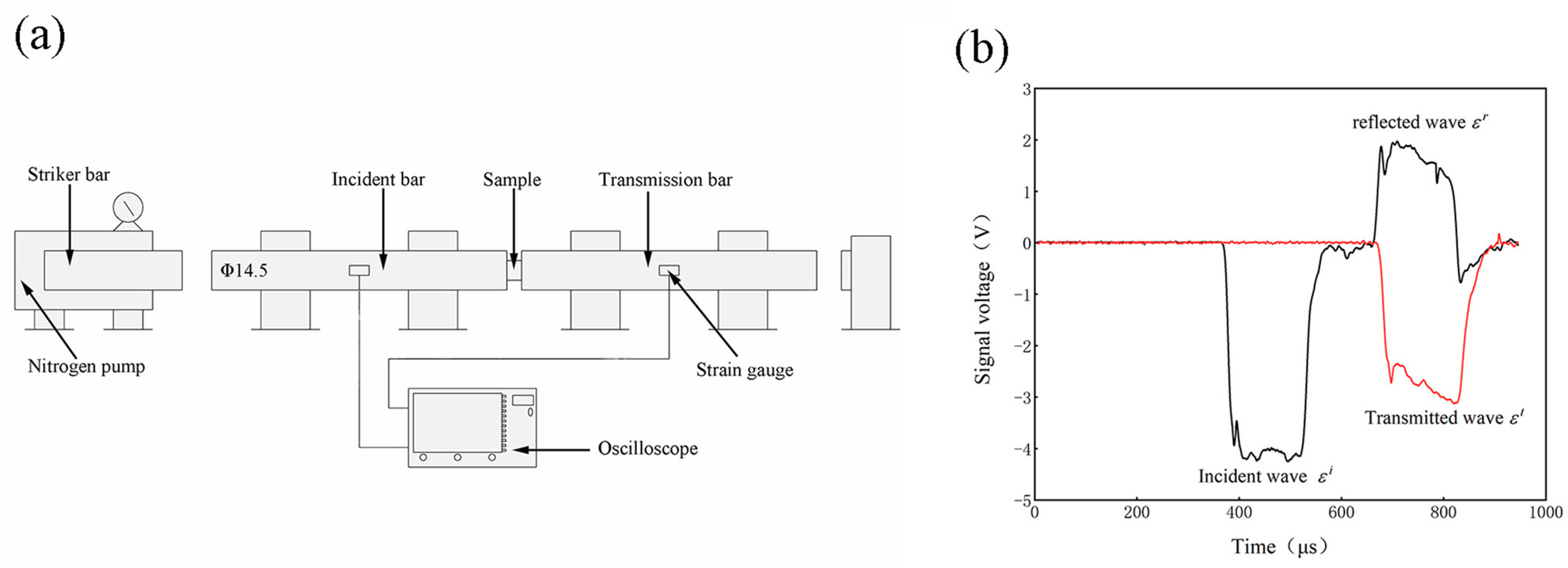
Figure 2.
(a) phase map; (b) KAM, and (c) IPF map of the samples.

Figure 3.
(a) The true stress–strain curves of the solution-treated samples under quasi-static and dynamic compression conditions as well as corresponding to the (b) strain-hardening rate.
Figure 3.
(a) The true stress–strain curves of the solution-treated samples under quasi-static and dynamic compression conditions as well as corresponding to the (b) strain-hardening rate.

Figure 4.
(a–d) show the dislocation morphology and deformation characteristics in both ferrite (a,b) and austenite (c,d) at the strain rate of 1500 s−1 after dynamic-compression deformation.
Figure 4.
(a–d) show the dislocation morphology and deformation characteristics in both ferrite (a,b) and austenite (c,d) at the strain rate of 1500 s−1 after dynamic-compression deformation.

Figure 5.
(a–d) show the dislocation morphology and deformation characteristics in both ferrite (a,b) and austenite (c,d) at a strain rate of 3144 s−1 after dynamic-compression deformation.
Figure 5.
(a–d) show the dislocation morphology and deformation characteristics in both ferrite (a,b) and austenite (c,d) at a strain rate of 3144 s−1 after dynamic-compression deformation.

Figure 6.
Comparison of the experimental results and constitutive model curves.
Disclaimer/Publisher’s Note: The statements, opinions and data contained in all publications are solely those of the individual author(s) and contributor(s) and not of MDPI and/or the editor(s). MDPI and/or the editor(s) disclaim responsibility for any injury to people or property resulting from any ideas, methods, instructions or products referred to in the content. |
© 2024 by the authors. Licensee MDPI, Basel, Switzerland. This article is an open access article distributed under the terms and conditions of the Creative Commons Attribution (CC BY) license (https://creativecommons.org/licenses/by/4.0/).
Share and Cite
MDPI and ACS Style
Cao, P.; Li, D.; Bai, S.; Chen, Y.; Lu, H. Dynamic Compression and Constitutive Model in Fe-27Mn-10Al-1C Duplex Lightweight Steel. Crystals 2024, 14, 178. https://doi.org/10.3390/cryst14020178
AMA Style
Cao P, Li D, Bai S, Chen Y, Lu H. Dynamic Compression and Constitutive Model in Fe-27Mn-10Al-1C Duplex Lightweight Steel. Crystals. 2024; 14(2):178. https://doi.org/10.3390/cryst14020178
Chicago/Turabian StyleCao, Pengfei, Dazhao Li, Shaobin Bai, Yongan Chen, and Haitao Lu. 2024. "Dynamic Compression and Constitutive Model in Fe-27Mn-10Al-1C Duplex Lightweight Steel" Crystals 14, no. 2: 178. https://doi.org/10.3390/cryst14020178
Note that from the first issue of 2016, this journal uses article numbers instead of page numbers. See further details here.