
From Batch to Continuous Small-Scale Production of Particles: Mixer Design Methodology for Robust Operation

Laboratory of Equipment Design, Department of Biochemical and Chemical Engineering, TU Dortmund University, Emil-Figge-Straße 68, 44227 Dortmund, Germany
*
Author to whom correspondence should be addressed.
Crystals 2024, 14(5), 398; https://doi.org/10.3390/cryst14050398
Submission received: 10 April 2024
/
Revised: 22 April 2024
/
Accepted: 23 April 2024
/
Published: 25 April 2024
(This article belongs to the Section Biomolecular Crystals)
Abstract
:Layered double hydroxides (LDHs) are a vital tool in many different areas, such as drug delivery, catalysis, anion exchange (materials), polymer processing, etc. Conventionally, LDHs are synthesized in a batch process that consists of particle generation and ripening, where product properties are manipulated for stability and the optimal uptake of genetic material. Continuous processing and intensive mixing holds high promise for improved particle generation and characteristic control. In this contribution, an iterative method, using the mentioned particle generation as a use case, was applied to quickly generate a continuous process optimization platform for continuous, plugging-free particle generation with the required characteristics. Assisted by rapid prototyping and additive manufacturing, a vortex mixer was produced that delivers satisfactory long-term results.
1. Introduction
Microreactors offer precise control over the intended reaction conditions [1,2]. The temperature, mixing regime, etc., can be accurately set, producing a product with homogeneous properties [2]. Although classical flow chemistry has utilized this concept for decades, the development of systems that are capable of the production of solids in microchannels is lagging behind [3,4]. This is mainly due to clogging and fouling in the channels, in most cases, caused by the desired product itself [3,5]. Since these products offer a variety of relevant applications, e.g., LDH drug delivery systems, as is the case in this work, research in this field is ongoing [3,4,5,6,7].
1.1. Layered Double Hydroxides
LDHs are ionic lamellar layered compounds that are classified as anionic clays and hydrotalcite-like structures [8,9,10,11,12,13]. Morphologically, they are small hexagonal crystals [9,14,15] composed of a large number of layers [8,16,17]. In the literature, LDH particles are described in the fields of catalysis, catalyst carriers, adsorbents, ion exchangers, polymer processing, electrodes, pharmacy, medicine, and evolutionary research [8,11,13,18,19,20,21]. LDHs have been prepared and characterized from various divalent and trivalent metal ion compositions [9,13,17,22,23]. The overall positive charge of the layers is balanced by intercalated, exchangeable anions () and water bound via hydrogen bonds, as demonstrated in Figure 1 [8,24].
A particularly important property of LDH is its ability to bind large molecules and release them again depending on the pH value, which makes LDH a suitable carrier for a wide variety of substances [13,18,20]. A specific use case is that of small interfering ribonucleic acid (siRNA) being bound and stabilized by the positively charged layers of LDH via the negatively charged “sugar-phosphate backbone” and released in the target cells by changing the pH value [16,20,21]. As mentioned above, LDH can be used for many different applications [13,18,20], which makes this contribution interesting for the production of LDH in general and not only for RNA applications.
There are a variety of synthesis methods for obtaining synthetic LDHs [13,15,18,25]. The coprecipitation method, which is the most relevant for this work, is commonly used due to the simple production, low costs, and high crystallinity of the product [13,24,25]. Coprecipitation consists of three steps: mixing of the metal salt solution with the base, homogeneous nucleation by supersaturation, and the subsequent growth of the particles from the nuclei [26]. During the production, all three steps can (very rapidly) happen at the same time and a distinction between them is therefore impossible from a macroscopic point of view [10].
Despite many different investigations [13,14,15,19,27,28], there is a lack of understanding of the exact formation mechanisms of LDH NPs. As a result, the potential of NPs cannot yet be fully exploited [29].
The desired properties of LDHs in terms of crystallinity and size cannot always be achieved during synthesis [10,13,29]. In a preceding hydrothermal treatment, the particle size and, in some cases, the crystallinity increases with increasing temperature and time [13,29,30]. The temperature is particularly decisive here [31]. Temperatures of up to 200 °C are used [31,32], often in the range of 60–150 °C [9,12,23,30,33,34]. The ripening time varies from a few hours to several days depending on the temperature, LDH, and target size [27,30,31,32,33,34].
1.2. Microreactors
Microreactors have gained attention in the pharmaceutical and chemical industry in the last 20-25 years and have since been developed for a wide range of applications [35,36]. The main characteristics are good mixing with easily controllable residence times and process conditions [35,37]. This enables for high yields with good selectivity. As they are a suitable tool for process intensification, they are often integrated into existing processes [38]. Micromixers are classified into passive and active mixers. Passive mixers work exclusively with the energy supplied from the pumped components, while active mixers require another source of energy input such as stirrers or ultrasound [35]. To describe the flow conditions, the Reynolds number (Re), defined as,
is often used with the characteristic length L, the related mean velocity , and the fluid properties of density and dynamic viscosity . The Re number identifies different flow regimes, classifying them into laminar, transient, and turbulent regimes [39]. Microreactors are often operated in the laminar or transient regime and have proven themselves to be a viable tool in research and development as well as in production processes. Numerous contributions that prove and discuss the benefits of microstructured devices exist [1,2,3,40,41,42]. These include increased heat and mass transfer due to the high surface-to-volume ratio, which enables for precise process control [2,41,42,43]. The microstructured channels and their mixing capabilities allow for reduced reaction times and, thus, decrease the necessary residence times, which, in turn, is a good starting point for process intensification [2,41,43]. Low internal volumes of the devices decrease the potential danger of hazardous substances, while resources are being saved [1,2,41,43]. Due to their potential in scale-up, by numbering up, etc., and the ease of integration in other continuous systems, microreactors have emerged to be extremely versatile and popular instruments [1,2,43].
The fabrication techniques of microfluidic parts can be divided into Microfabrication via photo and soft lithography and techniques such as micro-electro-discharge machining [1,42,44]. The second category is injection molding, where different polymerization techniques or thermosplasts come into play that are solidified to form the desired shape [1,44]. Finally, a recent technology to produce the above devices is additive manufacturing [45], which has made production more accessible due to low investment and operation costs [1,44,46,47]. Materials costs and production process costs as well as production times were reduced compared to the classical production routes. Additionally, this method is highly flexible and allows for the easy production of prototypes, for which the term rapid prototyping was coined.
1.3. Continuous Production of Solids in Microreactors
As discussed above, microreactors offer benefits that have motivated their application in the investigation of particles and their production processes. This includes modifying particle properties by the selection of the process, an example in which microreactors have been reported frequently [4,5,48]. This is also especially important in reactive crystallization or precipitation case studies [6,7,42,49,50,51,52,53], although applications in cooling crystallization, etc., also exist [54,55,56,57]. Precise temperature control and a continuous process character are major drivers for their application in cooling crystallization processes [55,56,57]. Precipitation processes, where the contact of reactant solutions causes rapid particle formation [58], were originally carried out batchwise without benefiting from the continuous operation scheme [59]. The production, however, can benefit from the fast mixing of the reactant solution and provide product particles with more homogeneous particle properties, which are desirable further downstream or for certain applications [4,5,48,59].
In line with expectations, the production of particles in microchannels presents a challenge regarding fouling and channel clogging, which hinders the continuous and reproducible operation of such devices to a large degree [4,5,48,59]. Different approaches concerning preventive surface treatment [4,60,61,62], particle surface modification [4,62], maintenance strategies [63,64], flow control and optimization [65], and optimized reactor design [44] have been proposed to address these challenges.
From the latter two, the following strategies have emerged. In microreactors with two-phase flow, the mixing is intensified by Taylor flow. This holds for the continuous and the disperse phase and also influences particles that are potentially carried in one of them [66]. On the one hand, this increases the mass and heat transfer; on the other hand, the tendency of clogging is reduced [67,68]. The respective devices may be made from materials such as silicon, polydimethylsiloxan (PDMS) or glass. They can also be created by simply using standard tubing from materials such as fluorinated ethylene propylene (FEP) [1,2,3]. By additionally using a coiled path of flow, the mixing is further intensified by Dean vortices due the centrifugal field [55,56,66].
The impinging jet mixer is often used in reactive crystallization or precipitation [69,70,71]. Here, two liquid streams (jets) collide (freely) and form a liquid sheet resulting in good mixing and, thus, the homogeneous formation of initial particles [69]. The jets usually meet in open air, but not necessarily [69]. Often, the resulting suspension is collected or passed on in equipment with increased dimensions where agglomeration can occur and needs to be prevented with additional measures [69,70,71]. The so-called vortex mixer or microreactors with swirling flow have multiple inlets that are tangentially connected to a mixing chamber where the streams meet [72,73,74]. The mixing chamber is often in the shape of a funnel with the point of highest mixing being close to the orifice [6]. Different implementations of this strategy exist with differences in the number of inlets, the size of channels and mixing chamber, and additional modifications such as the inlet channel position [6,7].
Further strategies to operate microstructured equipment with suspensions that do not necessarily include the reactor design include using pulsating flow and ultrasonic transducers [63,64,65,75,76].
The above considerations indicate that many facets of possible solutions to many different challenges exist and a holistic solution for all of them is beyond reality. Therefore, in this contribution, we demonstrate and discuss a method for a specific challenge regarding the conversion from the batch production of particles to an intensified continuous production. In particular, as discussed in the following, a piece of particle generation equipment was developed with the assistance of additive manufacturing and rapid prototyping.
2. Materials and Methods
For the transition of the LDH production from a batch to a continuous lab-scale process, rapid prototyping, via additive manufacturing, was used to ensure fast process development. Part of this development is defining and applying design criteria for the equipment (i.e., micromixer) itself. To qualitatively and quantitatively assess the design process and the outcome, analytical measures were taken into account. All of the above is described in detail in the following. Information on the suppliers of the chemicals and equipment used can be found in Table A1.
2.1. Process Development Strategy
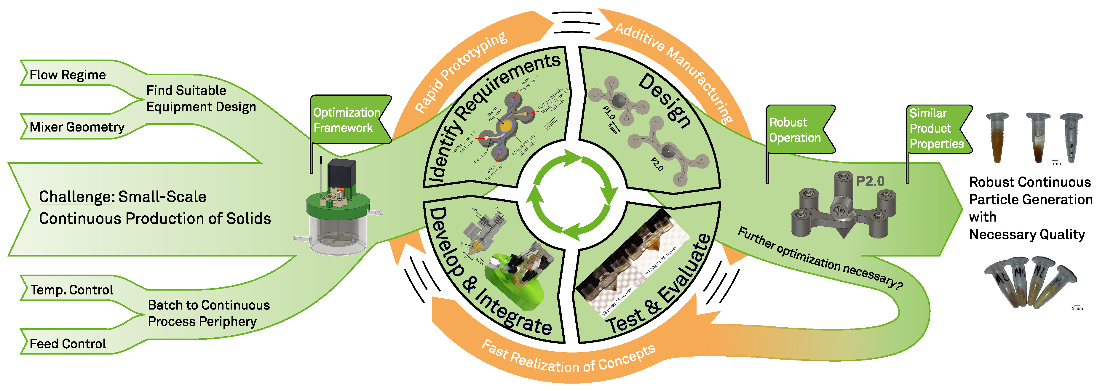
As described before, the goal of this work was to convert the classical batch process for the production of LDH clay into a continuous one. To visualize this (iterative) workflow, Figure 2 was created. Firstly, the critical operation parameter of the existing (batch) routine needed to be identified and options to transfer them to a continuous setup needed to be evaluated. When this optimization framework, where periphery and experimental setting were defined, was set up, the first prototypes for continuous operation could be introduced. Secondly, the continuous operation needed to be ensured by adjusting the operation parameters or equipment design. Lastly, by further optimizing these regulators, the process could be optimized with the results from the batch operation in mind.
The milestones (or hypotheses) that need to be met, in consecutive order, are as follows:
- The relevant batch process conditions can be suitably mapped in the continuous process;
- The continuous and robust operation can be ensured;
- The batch and continuous process produces the (interim) product with similar properties.
2.2. Optimization Framework for Continuous Operation
To be able to compare the batch and continuous experiments, the experimental optimization framework was developed with the batch conditions in mind. In the present case, the following equation holds for the reaction (derived from [21]):
The production of LDH via the batch route was performed as follows:
In total, 50 mL of MgCl2 · 6H2O (0.3 mol · L−1) and FeCl3 (0.1 mol · L−1) solution and 50 mL of NaOH (0.8 mol · L−1) solution were simultaneously added to a temperature-controlled (4 °C) reactor and stirred vigorously for 2 h (see Figure 3).
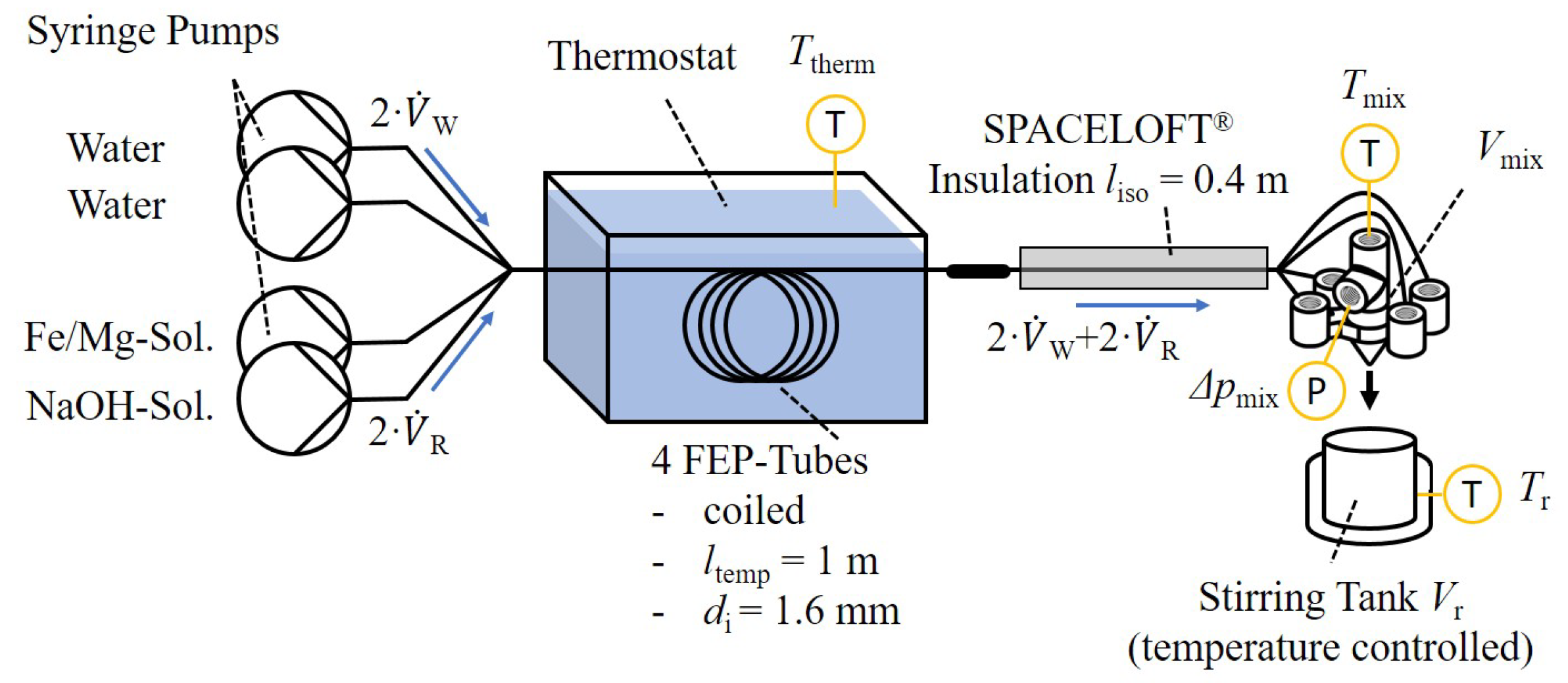
With this protocol, an LDH concentration of ca. 15 g · L−1 was to be expected. For analytical purposes, the suspension was further processed via washing with water, centrifuging, resuspending, and drying. Based on this protocol, the experimental setup for the continuous operation was designed. The respective flow diagram can be found in Figure 4. The reactant solutions and additional water were supplied via syringe pumps. The tubes ran from the pumps to the micromixer, where the initial reaction happened. From there, the same reaction vessel used for the batch experiment was filled with the suspension until a total of 100 mL was reached to copy the batch conditions. The temperature of the double jacketed reaction vessel was controlled with a thermostat. Regarding the cooling of the reactant solution, pre-chilling was substituted with a heat exchanger in the form of FEP tube coils in a second thermostat. The length of the tube in the thermostat was calculated with worst-case estimation according to [39] to be able to reach all target temperatures that were part of the process design. To decrease unwanted influences from the ambient temperature, the tubes exiting the thermostat were insulated on their way to the micromixer. The overall optimization framework enabled for the modification and, therefore, screening of the following parameters:
- Volumetric flow rate of the reactant ;
- Volumetric flow rate of water ;
- Reactant concentration (concentrations from the batch protocol are referred to as );
- Temperature in the micromixer via ;
- Temperature in the reaction vessel ;
- Ripening time after initial dosing in the reaction vessel;
- Design of the micromixer
The investigated output parameters that were considered throughout the optimization process are as follows:
- XRD patterns;
- Average crystal size D according to Section 2.4;
- General operability.
These were used to quantitatively and qualitatively evaluate the equipment that was under investigation.
2.3. Process and Equipment Design
To be able to continuously produce LDH in a microstructured device, it has to be ensured that the generated solids do not interfere with the operability of the device.
The micromixer concept used in this contribution works with a vortex principle. The reactant solution together with a water sheath flow are introduced into the mixing chamber in a tangential manner, as can be observed in Figure 5a. The individual channels of the species have a cross-section area of 1 mm·1 mm, setting the cross-section area of the channel after the meeting point at 2 mm2. The water sheath flow acts as a protective barrier with the goal of preventing the solids from coming into contact with the inner wall of the mixing chamber. The reactant solutions come into contact inside the funnel-shaped mixing chamber, generating a solid product that leaves the device into the reaction vessel. The mixer prototype demonstrated in Figure 5b has connections to be able to measure the temperature and pressure difference inside the mixing chamber. The internal threads of the connections comply with UNF 1/4” 28G to be able to connect with the standard laboratory fluidic periphery.
Since we were aiming for fast process development in this case, the devices were produced in-house via additive manufacturing using a stereolithography printer (Form 3+, Formlabs, MA, USA) with transparent resin (Clear Resin V4, Formlabs, MA, USA). The designs of the devices were flexibly adjusted using Fusion360 (Autodesk, Inc., San Francisco, CA, USA). In this way, experimental iteration, i.e., fabrication and the first experiments, between prototypes was possible within a single working day.
2.4. Measurement of Critical Product and Process Attributes
A method for investigating the properties of (crystalline) solids is powder X-ray diffraction (PXRD). A characteristic part of the X-ray radiation that the sample is subject to is reflected by the crystal structures and recorded with the deflection angle. The resulting diffractograms are used to draw conclusions about the crystal properties of the material under investigation, such as the crystal size, layer spacing, crystal and surface structure, phases, and much more [77,78,79,80]. In addition, the composition or type of the analyzed substance is determined by comparing the peak positions with literature data. The analysis of the PXRD diffractograms was performed according to Appendix A.3.
To gain insight into the investigated processes and mixing equipment, the temperature and the pressure in the mixing chamber were continuously recorded. Moreover, a visual inspection of the mixers during and after the synthesis processes were able to provide information about the mixing behavior and potential fouling or wall adhesion effects that might later hinder continuous operation in long-term studies.
3. Discussion of the Equipment Design Process
In the following, the equipment design process of the vortex mixer will be described and results will be discussed. For the sake of clarity, the iterations of the equipment are condensed in Table 1.
Starting with the batch conditions described in the production protocol and summarized in Table 2, the conditions for the continuous setup were derived and applied to P1.0 (comp. Table 1). The concept of the vortex mixer equipment with four inlets was to utilize the streams to the outside of the mixing chamber as the protective sheath flow. This was intended to reduce the adhesion of the generated particles to the walls of the mixing chamber. In order to obtain the same final product concentration as those of the batch experiments, the concentration of the reactant substances in was doubled since is water (Table 2: Continuous Set A). The continuous operation with these settings was not satisfactory from the operative point of view since clogging of the mixer was observed frequently. As a consequence, the flow rates were adjusted (Table 2: Continuous Set B) to obtain a bigger sheath flow (an increase from 1 mm to 1. mm inside the channel). Additionally, the total flow rate was increased from 20 mL · min−1 to 25 mL·min−1. Again, the concentrations were adjusted to stay consistent with the final concentrations from the batch experiments. Increasing the flow rate and sheath flow thickness had a positive effect on the operability of the equipment. At this point, the primary experiments with P1.0 of the mixer were successful. The device was still prone to clogging in the presented application, especially after numerous operations. To monitor this behavior, a connection for a pressure sensor was included for P1.1.
Not only was particle adhesion observed in the mixing chamber but also at the blunt tip where the outlet of the mixer is located. Therefore, the next iteration (P1.2) has a pointed tip, which was intended to reduce the area of the attack for this effect.
With the results gained by operating mixer P1.2 (Figure 6: C1 and C2), a comparison with the PXRD results from the batch experiments (Figure 6: B1 and B2) was conducted for the first time. Here, the calculated value D is of particular interest and was used for comparison purposes. The literature indicates that larger D values may influence the incorporation of RNA into the LDH, since the plane distance may be rising [20,81]. The diffractogram in Figure 6: B1 shows the results from the batch experiment with the standard experimental conditions demonstrated in Section 2.2. The literature indicates that an increased temperature during ripening has a positive effect on the crystal size; therefore, for sample B2, the temperature during the 2 h of ripening was increased to 65 °C [23]. For the experiment with the static mixer and the previously derived process conditions with the ripening also at 65 °C, the results in Figure 6 C1 were gained. The diffractograms until here demonstrate that the continuous operation was able to reproduce the results that were obtained from the batch experiments. The values for D, calculated via the Scherrer equation, support this.
For the next step, the temperature during mixing in the static mixer was also increased to 65 °C in order to achieve bigger crystals. The results of the PXRD measurement can be found in Figure 6 C2. Although 8.7 nm seems more promising than the previous results, the increase in to 65 °C caused a higher solid buildup and clogging during the mixing process. This can be seen in Figure 7. Longer operation times or several production campaigns with the same equipment are, therefore, not advisable at elevated temperatures.
As one can tell from Figure 7, also at default temperatures, the pressure difference increased periodically, which is a sign of solid buildup ( increase) and detachment ( decrease) in the fluid channels. It was hypothesized that the Y-mixer that contacted the reactant solution with the water sheath flow caused internal mixing of these two streams so that the protective water sheath was no longer functional. Therefore, for P2.0, the Y-mixer was adjusted in a way in which the two fluid streams merged in a more tangential manner to suppress any hydrodynamic mixing between the two streams, so that only diffusion was left as a counteracting effect. Long-term investigations (up to 10 individual experimental runs) supported this, as the operation of mixer P2.0 was more reliant than the operation of mixer P1.2.
For the next iteration step (mixer P2.1), a larger mixing chamber was provided. However, in this constellation, the inflow to the mixing chamber was not big enough to fill it up and, therefore, the vortex effect did not come into play. This can be clearly seen in Figure 8. Therefore, it is advisable to stick to P2.0 instead for P2.1 for further iterations. The iterative optimization process does not necessarily need to end here. With the mixer design P2.0, a robust platform for more systematic investigations was generated.
Rapid prototyping and an iterative workflow realized by additive manufacturing enabled a flexible optimization process for equipment design. In the course of this work, a starting point for the robust operation of LDH is presented.
4. Conclusions
Conventional methods for the production of layered double hydroxides (LDHs) require that the reactants are either spontaneously mixed by adding the solutions in a batch container or one of them is slowly added. In either case, the conditions for the formation of the primary particles change over the reaction time. This leaves room for improvement in terms of keeping the conditions constant during the reaction at every point in time. As presented in this work, simultaneously adding the reactant solutions via a static mixer seems promising.
As of now, the results gained with the continuous setup match those that from batch experiments, which serves as a good basis for process optimization. This is supported by the fact that initial process operation obstacles such as premature clogging or process instabilities seem to be overcome with mixer P2.0.
Utilizing the workflow that is described in this contribution, the design, generation, and the first experiments can be conducted within a single working day, which is considerably faster than classical production pathways that can take weeks. This presents a great opportunity for the rapid design, characterization, and application of successful microfluidic devices, assisting in the development of different continuous production processes. The LDH produced in the presented work was not investigated in combination with a specific use case; however, the design and optimization framework may be interesting as a general approach for LDH production and a variety of related applications.
Author Contributions
Conceptualization, S.H. and N.K.; methodology, S.H. and N.K.; investigation, P.R.; data curation, S.H. and P.R.; writing—original draft preparation, S.H.; writing—review and editing, S.H. and N.K.; visualization, S.H. and P.R.; supervision, S.H. and N.K.; project administration, N.K.; funding acquisition, N.K. All authors have read and agreed to the published version of the manuscript.
Funding
This research was partly funded Nufarm Limited (Melbourne, Australia).
Data Availability Statement
The original contributions presented in the study are included in the article, further inquiries can be directed to the corresponding author.
Acknowledgments
We would like to thank Oleg Werbitzky and the partners from Nufarm for the helpful and fruitful discussions.
Conflicts of Interest
The authors declare no conflicts of interest.
Abbreviations
The following abbreviations are used in this manuscript:
| FEP | Fluorinated Ethylene Propylene |
| FWHM | Full Width at Half Maximum |
| HT | Hydrothermal |
| LDH | Layered Double Hydroxides |
| NP | Nano Particles |
| PDMS | Polydimethylsiloxan |
Appendix A
Appendix A.1. Hardware Used

Table A1.
Utilized substances and equipment.
| Substance | Supplier | Purity | Lot |
|---|---|---|---|
| NaOH | Sigma Aldrich®, MO, USA | ≥97% | MB2029962 201 |
| FeCl3 | Sigma Aldrich®, MO, USA | ≥98% | S8262845 225 |
| MgCl2 · 6H2O | VWR Chemicals, PA, USA | ≥98% | 22A054107 |
| Equipment | Supplier | Name | Label |
| Pressure sensor | AFRISO-EURO-INDEX GmbH | DMU 01 ST − 1/+3 bar | |
| Lab Automation | HiTec Zang GmbH | LabManager® | - |
| pH-electrode | WTW | SenTix® 940 | - |
| Stirrer Motor | Nanotec Electronic GmbH & Co. KG | Nema 17 | |
| Motor driver | Pololu, Las Vegas, USA | Tic T825 | - |
| Syringe | Henke-Sass, Wolf GmbH | HENKE-JECT® Luer Lock 50 mL | - |
| Syringe pump | LAMBDA Instruments GmbH | Lambda Vit-Fit | , |
| Temperature sensor | Rössel-Messtechnik GmbH | Pt-B-100-2 | , |
| Thermostat | Huber Kältemaschinenbau AG | Ministat 125 | - |
| Vacuum oven | Memmert GmbH & Co. KG | Memmert VO400 | - |
| Vacuum pump | VACUUBRAND GmbH & Co. KG | PC3001 VARIOpro | - |
| Centrifuge | Witeg Labortechnik GmbH | WiseSpin CF-10 | - |
| 3D printer | Formlabs | Form3+ | - |
Appendix A.2. Modification to Syringe Pumps
Figure A1.
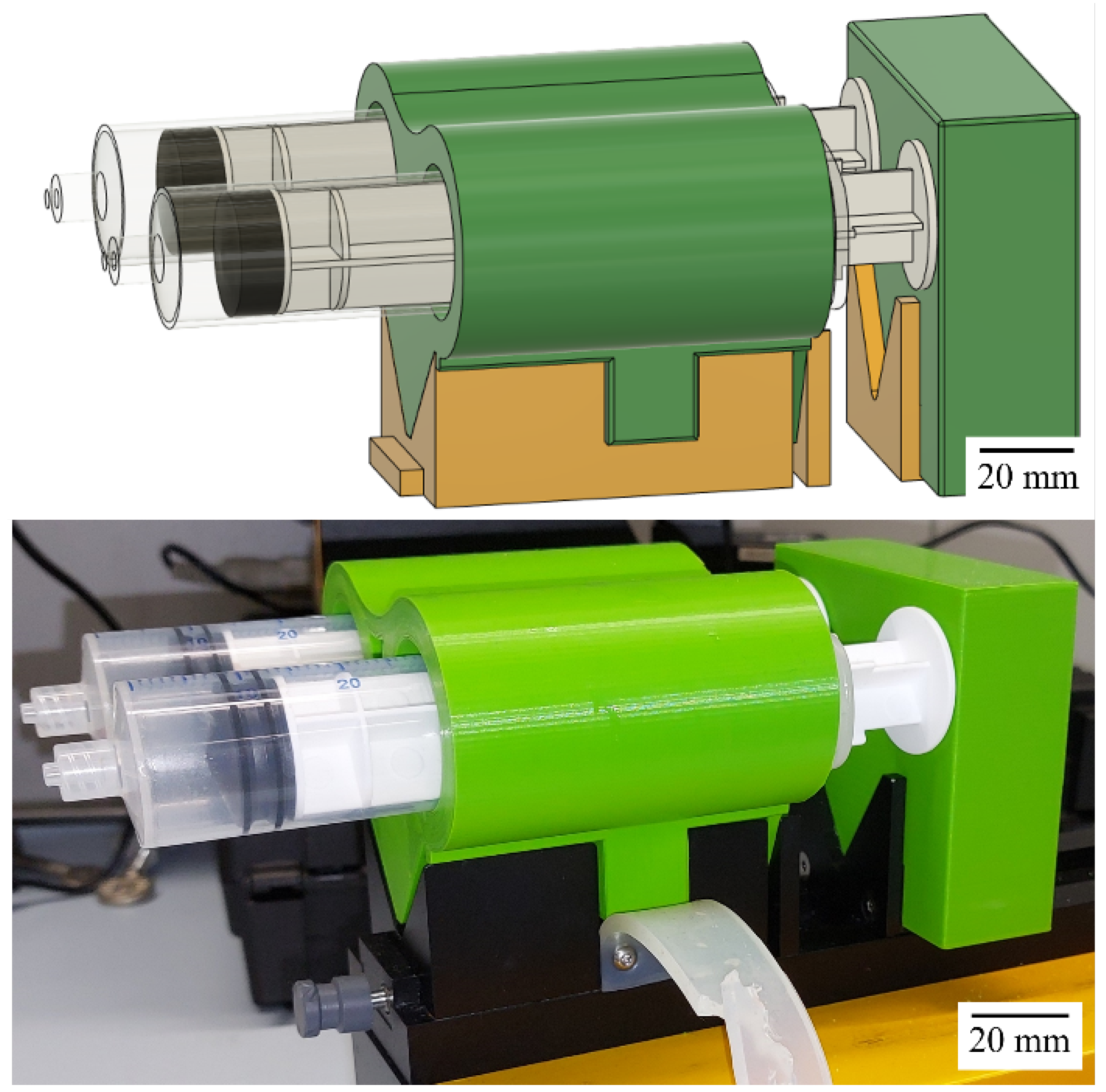
CAD sketch and photograph of the add-on to extend the capacity of the syringe pumps to two syringes.
Figure A1.
CAD sketch and photograph of the add-on to extend the capacity of the syringe pumps to two syringes.
Appendix A.3. PXRD Measurements and Scherrer Equation
In the presented case, the Miniflex 600 (Rigaku Corporation, Tokio, Japan) was used, which is equipped with a Cu-anode and works with a weighted average wavelength of nm [80]. For the analysis, 100–250 mg of dried and pestled product was necessary. The applied drying protocol was the following:
- 1.
- Centrifuging of samples (12,000 rpm, 3 min) and discarding the liquid;
- 2.
- Washing (resuspending) solids with water with subsequent centrifugation (12,000 rpm, 3 min) and discarding of the liquid;
- 3.
- Repetition of washing until a total of three washing steps was reached;
- 4.
- Drying of solids in a vacuum oven (at least 20 h, 200 mbar, 30 °C).
From the X-ray powder diffractogram, the average crystal size D, vertical to the reflecting lattice, can be calculated according to the Scherrer equation:
with the Scherrer constant 0.89 according to [77,79,80,82], the emitted wavelength , the Full Width at Half Maximum (FWHM) value of the analyzed peak in the diffractrogram, and the Bragg angle 2 of the peak of interest. In addition to D, the diffractograms themselves, which can provide information about the crystallinity and composition, were also compared to each other.
Appendix A.4. Reactor Setup
Figure A2.
Setup for the visual investigation of the different mixers.

References
- Suryawanshi, P.L.; Gumfekar, S.P.; Bhanvase, B.A.; Sonawane, S.H.; Pimplapure, M.S. A review on microreactors: Reactor fabrication, design, and cutting-edge applications. Chem. Eng. Sci. 2018, 189, 431–448. [Google Scholar] [CrossRef]
- Wang, X.; Liu, Z.; Wang, B.; Cai, Y.; Song, Q. An overview on state-of-art of micromixer designs, characteristics and applications. Anal. Chim. Acta 2023, 1279, 341685. [Google Scholar] [CrossRef] [PubMed]
- Gimondi, S.; Ferreira, H.; Reis, R.L.; Neves, N.M. Microfluidic Devices: A Tool for Nanoparticle Synthesis and Performance Evaluation. ACS Nano 2023, 17, 14205–14228. [Google Scholar] [CrossRef] [PubMed]
- Hartman, R.L. Managing Solids in Microreactors for the Upstream Continuous Processing of Fine Chemicals. Org. Process Res. Dev. 2012, 16, 870–887. [Google Scholar] [CrossRef]
- Zong, J.; Yue, J. Continuous Solid Particle Flow in Microreactors for Efficient Chemical Conversion. Ind. Eng. Chem. Res. 2022, 61, 6269–6291. [Google Scholar] [CrossRef]
- Abiev, R.; Almjasheva, O.; Popkov, V.; Proskurina, O. Microreactor synthesis of nanosized particles: The role of micromixing, aggregation, and separation processes in heterogeneous nucleation. Chem. Eng. Res. Des. 2022, 178, 73–94. [Google Scholar] [CrossRef]
- Abiev, R.S.; Kudryashova, Y.S.; Zdravkov, A.V.; Fedorenko, N.Y. Micromixing and Co-Precipitation in Continuous Microreactors with Swirled Flows and Microreactors with Impinging Swirled Flows. Inorganics 2023, 11, 49. [Google Scholar] [CrossRef]
- Arrabito, G.; Bonasera, A.; Prestopino, G.; Orsini, A.; Mattoccia, A.; Martinelli, E.; Pignataro, B.; Medaglia, P. Layered Double Hydroxides: A Toolbox for Chemistry and Biology. Crystals 2019, 9, 361. [Google Scholar] [CrossRef]
- Kuang, Y.; Zhao, L.; Zhang, S.; Zhang, F.; Dong, M.; Xu, S. Morphologies, Preparations and Applications of Layered Double Hydroxide Micro-/Nanostructures. Materials 2010, 3, 5220–5235. [Google Scholar] [CrossRef]
- Sun, X.; Neuperger, E.; Dey, S.K. Insights into the synthesis of layered double hydroxide (LDH) nanoparticles: Part 1. Optimization and controlled synthesis of chloride-intercalated LDH. J. Colloid Interface Sci. 2015, 459, 264–272. [Google Scholar] [CrossRef]
- Dębek, R.; Motak, M.; Grzybek, T.; Galvez, M.; Da Costa, P. A Short Review on the Catalytic Activity of Hydrotalcite-Derived Materials for Dry Reforming of Methane. Catalysts 2017, 7, 32. [Google Scholar] [CrossRef]
- Xiong, P.; Ji, X.; Zhao, X.; Lv, W.; Liu, T.; Lu, W. Materials design and control synthesis of the layered double hydroxide with the desired basal spacing. Chemometr. Intell. Lab. 2015, 144, 11–16. [Google Scholar] [CrossRef]
- Auerbach, S.M.; Carrado, K.A.; Dutta, P.K. Handbook of Layered Materials; CRC Press: Boca Raton, FL, USA, 2004. [Google Scholar] [CrossRef]
- Vucelic, M. Cation Ordering in Synthetic Layered Double Hydroxides. Clay Clay Miner. 1997, 45, 803–813. [Google Scholar] [CrossRef]
- Wijitwongwan, R.; Intasa-ard, S.; Ogawa, M. Preparation of Layered Double Hydroxides toward Precisely Designed Hierarchical Organization. Chem. Eng. 2019, 3, 68. [Google Scholar] [CrossRef]
- Ladewig, K.; Niebert, M.; Xu, Z.P.; Gray, P.P.; Lu, G.Q.M. Efficient siRNA delivery to mammalian cells using layered double hydroxide nanoparticles. Biomaterials 2010, 31, 1821–1829. [Google Scholar] [CrossRef]
- Balcomb, B.; Singh, M.; Singh, S. Synthesis and characterization of layered double hydroxides and their potential as nonviral gene delivery vehicles. ChemistryOpen 2015, 4, 137–145. [Google Scholar] [CrossRef]
- Mishra, G.; Dash, B.; Pandey, S. Layered double hydroxides: A brief review from fundamentals to application as evolving biomaterials. Appl. Clay Sci. 2018, 153, 172–186. [Google Scholar] [CrossRef]
- Shanmuganathan, K.; Ellison, C.J. Layered Double Hydroxides. In Polymer Green Flame Retardants; Elsevier: Amsterdam, The Netherlands, 2014; pp. 675–707. [Google Scholar] [CrossRef]
- Andrea, K.A.; Wang, L.; Carrier, A.J.; Campbell, M.; Buhariwalla, M.; Mutch, M.; MacQuarrie, S.L.; Bennett, C.; Mkandawire, M.; Oakes, K.; et al. Adsorption of Oligo-DNA on Magnesium Aluminum-Layered Double-Hydroxide Nanoparticle Surfaces: Mechanistic Implication in Gene Delivery. Langmuir 2017, 33, 3926–3933. [Google Scholar] [CrossRef]
- Jain, R.G.; Fletcher, S.J.; Manzie, N.; Robinson, K.E.; Li, P.; Lu, E.; Brosnan, C.A.; Xu, Z.P.; Mitter, N. Foliar application of clay-delivered RNA interference for whitefly control. Nat. Plants 2022, 8, 535–548. [Google Scholar] [CrossRef]
- Wang, Q.; O’Hare, D. Recent advances in the synthesis and application of layered double hydroxide (LDH) nanosheets. Chem. Rev. 2012, 112, 4124–4155. [Google Scholar] [CrossRef]
- Tathod, A.P.; Gazit, O.M. Fundamental Insights into the Nucleation and Growth of Mg–Al Layered Double Hydroxides Nanoparticles at Low Temperature. Cryst. Growth Des. 2016, 16, 6709–6713. [Google Scholar] [CrossRef]
- Taviot-Guého, C.; Prévot, V.; Forano, C.; Renaudin, G.; Mousty, C.; Leroux, F. Tailoring Hybrid Layered Double Hydroxides for the Development of Innovative Applications. Adv. Funct. Mater. 2018, 28, 1703868. [Google Scholar] [CrossRef]
- Ameena Shirin, V.K.; Sankar, R.; Johnson, A.P.; Gangadharappa, H.V.; Pramod, K. Advanced drug delivery applications of layered double hydroxide. J. Control. Release 2021, 330, 398–426. [Google Scholar] [CrossRef]
- Porter, D.A.; Easterling, K.E. Phase Transformations in Metals and Alloys (Revised Reprint); CRC Press: Boca Raton, FL, USA, 2009. [Google Scholar] [CrossRef]
- Zhao, Y.; Li, F.; Zhang, R.; Evans, D.G.; Duan, X. Preparation of Layered Double-Hydroxide Nanomaterials with a Uniform Crystallite Size Using a New Method Involving Separate Nucleation and Aging Steps. Chem. Mater. 2002, 14, 4286–4291. [Google Scholar] [CrossRef]
- Yun, S.K.; Pinnavaia, T.J. Water Content and Particle Texture of Synthetic Hydrotalcite-like Layered Double Hydroxides. Chem. Mater. 1995, 7, 348–354. [Google Scholar] [CrossRef]
- Sun, X.; Dey, S.K. Insights into the synthesis of layered double hydroxide (LDH) nanoparticles: Part 2. Formation mechanisms of LDH. J. Colloid Interface Sci. 2015, 458, 160–168. [Google Scholar] [CrossRef]
- Oh, J. The effect of synthetic conditions on tailoring the size of hydrotalcite particles. Solid State Ion. 2002, 151, 285–291. [Google Scholar] [CrossRef]
- Van der Pol, A.; Mojet, B.L.; van de Ven, E.; de Boer, E. Ordering of Intercalated Water and Carbonate Anions in Hydrotalcite. An NMR Study. J. Phys. Chem. 1994, 98, 4050–4054. [Google Scholar] [CrossRef]
- Miyata, S. Physico-Chemical Properties of Synthetic Hydrotalcites in Relation to Composition. Clay Clay Miner. 1980, 28, 50–56. [Google Scholar] [CrossRef]
- Grégoire, B.; Ruby, C.; Carteret, C. Hydrolysis of mixed Ni2+-Fe3+ and Mg2+-Fe3+ solutions and mechanism of formation of layered double hydroxides. Dalton Trans. 2013, 42, 15687–15698. [Google Scholar] [CrossRef]
- Radha, A.V.; Kamath, P.V.; Shivakumara, C. Order and disorder among the layered double hydroxides: Combined Rietveld and DIFFaX approach. Acta Crystallogr. B 2007, 63, 243–250. [Google Scholar] [CrossRef]
- Hessel, V.; Löwe, H.; Schönfeld, F. Micromixers—A review on passive and active mixing principles. Chem. Eng. Sci. 2005, 60, 2479–2501. [Google Scholar] [CrossRef]
- Tonomura, O.; Nishida, A.; Wang, L.; Hasebe, S. Optimal channel design and sensor placement in flow distributors for detecting blockage of parallelized microreactors. In 11th International Symposium on Process Systems Engineering; Elsevier: Amsterdam, The Netherlands, 2012; Volume 31, pp. 1281–1285. [Google Scholar] [CrossRef]
- Kockmann, N. Transport Processes and Exchange Equipment. In Micro Process Engineering; Kockmann, N., Ed.; Advanced Micro and Nanosystems, Wiley: Hoboken, NJ, USA, 2006; pp. 71–113. [Google Scholar] [CrossRef]
- Veser, G.; Friedrich, G.; Freygang, M.; Zengerle, R. A Simple and Flexible Micro Reactor for Investigations on Heterogeneous Catalytic Gas Phase Reactions. In Proceedings of the Micro-Electro-Mechanical Systems (MEMS), Anaheim, CA, USA, 15–20 November 1998; pp. 199–206. [Google Scholar] [CrossRef]
- VDI (Ed.) VDI-Wärmeatlas; Springer: Berlin/Heidelberg, Germany, 2013. [Google Scholar] [CrossRef]
- Aralekallu, S.; Boddula, R.; Singh, V. Development of glass-based microfluidic devices: A review on its fabrication and biologic applications. Mater. Des. 2023, 225, 111517. [Google Scholar] [CrossRef]
- Jähnisch, K.; Hessel, V.; Löwe, H.; Baerns, M. Chemistry in Microstructured Reactors. Angew. Chem. Int. Ed. 2004, 43, 406–446. [Google Scholar] [CrossRef]
- Yao, X.; Zhang, Y.; Du, L.; Liu, J.; Yao, J. Review of the applications of microreactors. Renew. Sustain. Energy Rev. 2015, 47, 519–539. [Google Scholar] [CrossRef]
- Kockmann, N.; Roberge, D.M. Scale-up concept for modular microstructured reactors based on mixing, heat transfer, and reactor safety. Chem. Eng. Process. Process Intensif. 2011, 50, 1017–1026. [Google Scholar] [CrossRef]
- Bojang, A.A.; Wu, H.S. Design, Fundamental Principles of Fabrication and Applications of Microreactors. Processes 2020, 8, 891. [Google Scholar] [CrossRef]
- Amores, I.D.; González-Gutiérrez, J.; García, I.M.; Franco, J.M.; Gallegos, C. 3D printing–Present and future–A Chemical Engineering perspective. Chem. Eng. Res. Des. 2022, 187, 598–610. [Google Scholar] [CrossRef]
- Sun, H.; Jia, Y.; Dong, H.; Dong, D.; Zheng, J. Combining additive manufacturing with microfluidics: An emerging method for developing novel organs-on-chips. Curr. Opin. Chem. Eng. 2020, 28, 1–9. [Google Scholar] [CrossRef]
- Parra-Cabrera, C.; Achille, C.; Kuhn, S.; Ameloot, R. 3D printing in chemical engineering and catalytic technology: Structured catalysts, mixers and reactors. Chem. Soc. Rev. 2018, 47, 209–230. [Google Scholar] [CrossRef]
- Wang, H.; Mustaffar, A.; Phan, A.N.; Zivkovic, V.; Reay, D.; Law, R.; Boodhoo, K. A review of process intensification applied to solids handling. Chem. Eng. Process. Process Intensif. 2017, 118, 78–107. [Google Scholar] [CrossRef]
- Poe, S.L.; Cummings, M.A.; Haaf, M.P.; McQuade, D.T. Solving the Clogging Problem: Precipitate-Forming Reactions in Flow. Angew.-Chem.-Int. Ed. 2006, 118, 1574–1578. [Google Scholar] [CrossRef]
- Jiang, X.; Chen, X.; Ling, C.; Chen, S.; Wu, Z. High-performance Cu/ZnO catalysts prepared using a three-channel microreactor. Appl. Catal. A 2019, 570, 192–199. [Google Scholar] [CrossRef]
- Kockmann, N.; Kastener, J.; Woias, P. Reactive particle precipitation in liquid microchannel flow. Chem. Eng. J. 2008, 135, S110–S116. [Google Scholar] [CrossRef]
- Castro, F.; Kuhn, S.; Jensen, K.; Ferreira, A.; Rocha, F.; Vicente, A.; Teixeira, J.A. Continuous-flow precipitation of hydroxyapatite in ultrasonic microsystems. Chem. Eng. J. 2013, 215–216, 979–987. [Google Scholar] [CrossRef]
- Liu, Z.; Yang, M.; Zhao, Q.; Yao, C.; Chen, G. Scale-up of antisolvent precipitation process with ultrasonic microreactors: Cavitation patterns, mixing characteristics and application in nanoparticle manufacturing. Chem. Eng. J. 2023, 475, 146040. [Google Scholar] [CrossRef]
- Giri, G.; Yang, L.; Mo, Y.; Jensen, K.F. Adding Crystals To Minimize Clogging in Continuous Flow Synthesis. Cryst. Growth Des. 2018, 19, 98–105. [Google Scholar] [CrossRef]
- Hohmann, L.; Greinert, T.; Mierka, O.; Turek, S.; Schembecker, G.; Bayraktar, E.; Wohlgemuth, K.; Kockmann, N. Analysis of Crystal Size Dispersion Effects in a Continuous Coiled Tubular Crystallizer: Experiments and Modeling. Cryst. Growth Des. 2018, 18, 1459–1473. [Google Scholar] [CrossRef]
- Schmalenberg, M.; Kreis, S.; Weick, L.K.; Haas, C.; Sallamon, F.; Kockmann, N. Continuous Cooling Crystallization in a Coiled Flow Inverter Crystallizer Technology—Design, Characterization, and Hurdles. Processes 2021, 9, 1537. [Google Scholar] [CrossRef]
- Coliaie, P.; Kelkar, M.S.; Korde, A.; Langston, M.; Liu, C.; Nazemifard, N.; Patience, D.; Skliar, D.; Nere, N.K.; Singh, M.R. On-the-spot quenching for effective implementation of cooling crystallization in a continuous-flow microfluidic device. React. Chem. Eng. 2022, 7, 1179–1190. [Google Scholar] [CrossRef]
- Kramer, A.L.M.S.H.; van Rosmalen, G. Precipitation and anti-solvent crystallization. In Industrial Crystallization: Fundamentals and Applications; Cambridge University Press: Cambridge, UK, 2015; Chapter 11; pp. 234–260. [Google Scholar] [CrossRef]
- Plutschack, M.B.; Pieber, B.; Gilmore, K.; Seeberger, P.H. The Hitchhiker’s Guide to Flow Chemistry. Chem. Rev. 2017, 117, 11796–11893. [Google Scholar] [CrossRef]
- Kuhn, S.; Hartman, R.L.; Sultana, M.; Nagy, K.D.; Marre, S.; Jensen, K.F. Teflon-Coated Silicon Microreactors: Impact on Segmented Liquid-Liquid Multiphase Flows. Langmuir 2011, 27, 6519–6527. [Google Scholar] [CrossRef]
- Kuhn, S.; Noël, T.; Gu, L.; Heider, P.L.; Jensen, K.F. A Teflon microreactor with integrated piezoelectric actuator to handle solid forming reactions. Lab Chip 2011, 11, 2488. [Google Scholar] [CrossRef]
- Flowers, B.S.; Hartman, R.L. Particle Handling Techniques in Microchemical Processes. Challenges 2012, 3, 194–211. [Google Scholar] [CrossRef]
- Delacour, C.; Lutz, C.; Kuhn, S. Pulsed ultrasound for temperature control and clogging prevention in micro-reactors. Ultrason. Sonochem. 2019, 55, 67–74. [Google Scholar] [CrossRef]
- Banakar, V.; Sabnis, S.; Gogate, P.; Raha, A.; Saurabh. Ultrasound assisted continuous processing in microreactors with focus on crystallization and chemical synthesis: A critical review. Chem. Eng. Res. Des. 2022, 182, 273–289. [Google Scholar] [CrossRef]
- Wu, K.; Kuhn, S. Strategies for solids handling in microreactors. Chim. Oggi. 2014, 32, 62. [Google Scholar]
- Kurt, S.K.; Akhtar, M.; Nigam, K.D.P.; Kockmann, N. Continuous Reactive Precipitation in a Coiled Flow Inverter: Inert Particle Tracking, Modular Design, and Production of Uniform CaCO3 Particles. Ind. Eng. Chem. Res. 2017, 56, 11320–11335. [Google Scholar] [CrossRef]
- Kumar, V.; Mridha, M.; Gupta, A.; Nigam, K. Coiled flow inverter as a heat exchanger. Chem. Eng. Sci. 2007, 62, 2386–2396. [Google Scholar] [CrossRef]
- Mridha, M.; Nigam, K. Coiled flow inverter as an inline mixer. Chem. Eng. Sci. 2008, 63, 1724–1732. [Google Scholar] [CrossRef]
- Johnson, B.K.; Prud’homme, R.K. Chemical processing and micromixing in confined impinging jets. AlChE J. 2003, 49, 2264–2282. [Google Scholar] [CrossRef]
- Mahajan, A.J.; Kirwan, D.J. Micromixing effects in a two-impinging-jets precipitator. AlChE J. 1996, 42, 1801–1814. [Google Scholar] [CrossRef]
- Han, J.; Zhu, Z.; Qian, H.; Wohl, A.R.; Beaman, C.J.; Hoye, T.R.; Macosko, C.W. A simple confined impingement jets mixer for flash nanoprecipitation. J. Pharm. Sci. 2012, 101, 4018–4023. [Google Scholar] [CrossRef] [PubMed]
- Pal, S.; Madane, K.; Kulkarni, A.A. Antisolvent based precipitation: Batch, capillary flow reactor and impinging jet reactor. Chem. Eng. J. 2019, 369, 1161–1171. [Google Scholar] [CrossRef]
- Liu, Y.; Cheng, C.; Liu, Y.; Prud’homme, R.K.; Fox, R.O. Mixing in a multi-inlet vortex mixer (MIVM) for flash nano-precipitation. Chem. Eng. Sci. 2008, 63, 2829–2842. [Google Scholar] [CrossRef]
- Markwalter, C.E.; Prud’homme, R.K. Design of a Small-Scale Multi-Inlet Vortex Mixer for Scalable Nanoparticle Production and Application to the Encapsulation of Biologics by Inverse Flash NanoPrecipitation. J. Pharm. Sci. 2018, 107, 2465–2471. [Google Scholar] [CrossRef]
- Fernandez Rivas, D.; Kuhn, S. Synergy of Microfluidics and Ultrasound: Process Intensification Challenges and Opportunities. Top. Curr. Chem. 2016, 374, 70. [Google Scholar] [CrossRef] [PubMed]
- Zhao, S.; Zhao, Q.; Yao, C.; Chen, G. Investigation of anti-clogging mechanism of ultrasound-driven oscillating slugs/bubbles and its application on continuous crystallization process. Chem. Eng. Sci. 2024, 290, 119898. [Google Scholar] [CrossRef]
- Cullity, B.D. Elements of X-ray Diffraction; Addison-Wesley Series in Metallurgy and Materials; Addison-Wesley: Boston, MA, USA, 1978. [Google Scholar]
- Klug, H.P.; Alexander, L.E. X-ray Diffraction Procedures for Polycrystalline and Amorphous Materials, 2nd ed.; John Wiley: New York, NY, USA, 1974. [Google Scholar]
- Krischner, H. Einführung in die Röntgenfeinstrukturanalyse; Vieweg+Teubner Verlag: Wiesbaden, Germany, 1990. [Google Scholar] [CrossRef]
- Spieß, L.; Teichert, G.; Schwarzer, R.; Behnken, H.; Genzel, C. Moderne Röntgenbeugung; Springer Fachmedien Wiesbaden: Wiesbaden, Germany, 2019. [Google Scholar] [CrossRef]
- Lu, M.; Shan, Z.; Andrea, K.; MacDonald, B.; Beale, S.; Curry, D.E.; Wang, L.; Wang, S.; Oakes, K.D.; Bennett, C.; et al. Chemisorption Mechanism of DNA on Mg/Fe Layered Double Hydroxide Nanoparticles: Insights into Engineering Effective SiRNA Delivery Systems. Langmuir 2016, 32, 2659–2667. [Google Scholar] [CrossRef]
- Hargreaves, J.S.J. Some considerations related to the use of the Scherrer equation in powder X-ray diffraction as applied to heterogeneous catalysts. Catal. Struct. React. 2016, 2, 33–37. [Google Scholar] [CrossRef]
Figure 1.
Schematic of the general structure of LDH layers where the mass fraction x = = 0.25 and m is the number of water molecules.
Figure 1.
Schematic of the general structure of LDH layers where the mass fraction x = = 0.25 and m is the number of water molecules.
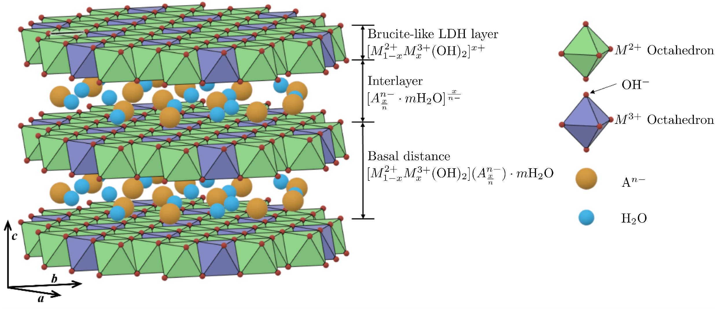
Figure 2.
Optimization process for the developed micromixer equipment from the idea and requirements to the finished product, which delivers an optimal, robust, and satisfactory functional prototype or product.
Figure 2.
Optimization process for the developed micromixer equipment from the idea and requirements to the finished product, which delivers an optimal, robust, and satisfactory functional prototype or product.

Figure 3.
Image of the micromixer connected to the ripening vessel in (a) and CAD sketch in (b).
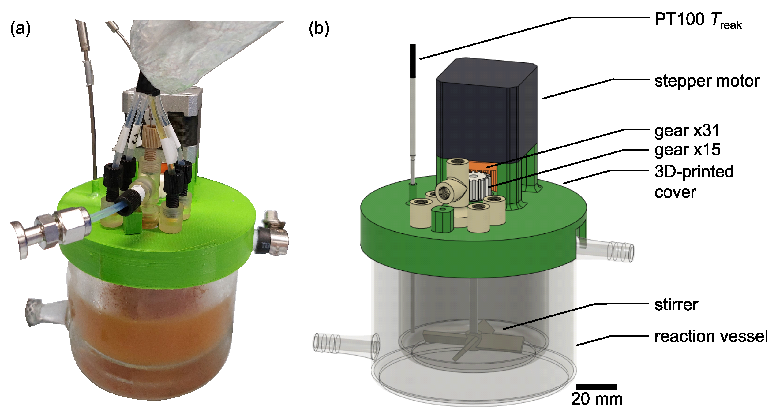
Figure 4.
Flow diagram of the optimization framework used for the continuous operation. The mixing equipment on the far right can be flexibly interchanged. An image of the pumps can be found in Figure A1.
Figure 4.
Flow diagram of the optimization framework used for the continuous operation. The mixing equipment on the far right can be flexibly interchanged. An image of the pumps can be found in Figure A1.

Figure 5.
(a) Schematic cross-section view of a possible mixer design from the top. (b) Cross-section view of the mixing chamber of a possible mixer design from the side.
Figure 5.
(a) Schematic cross-section view of a possible mixer design from the top. (b) Cross-section view of the mixing chamber of a possible mixer design from the side.

Figure 6.
Diffractograms of batch samples B1 and B2 and continuous samples C1 and C2. Planes (003), (006), and (012) are indicated. The characteristic peak at ≈11 nm was used for the evaluation via the Scherrer equation. The calculated values for are given. The baseline and Gaussian peak were determined with the help of the Peak Analyzer tool in OriginPro.
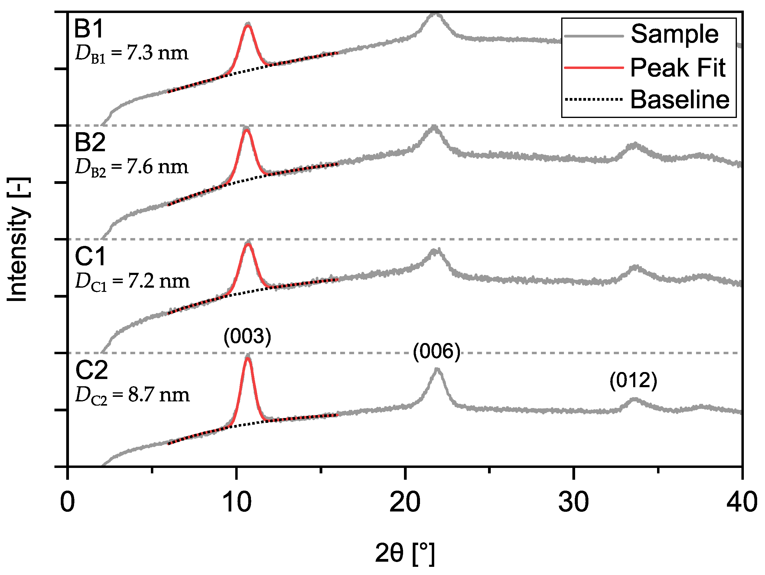
Figure 7.
Differential pressure curves from inside the mixing chamber of mixer P1.2 operated at two different temperatures. The temperature is averaged across the experiment.
Figure 7.
Differential pressure curves from inside the mixing chamber of mixer P1.2 operated at two different temperatures. The temperature is averaged across the experiment.
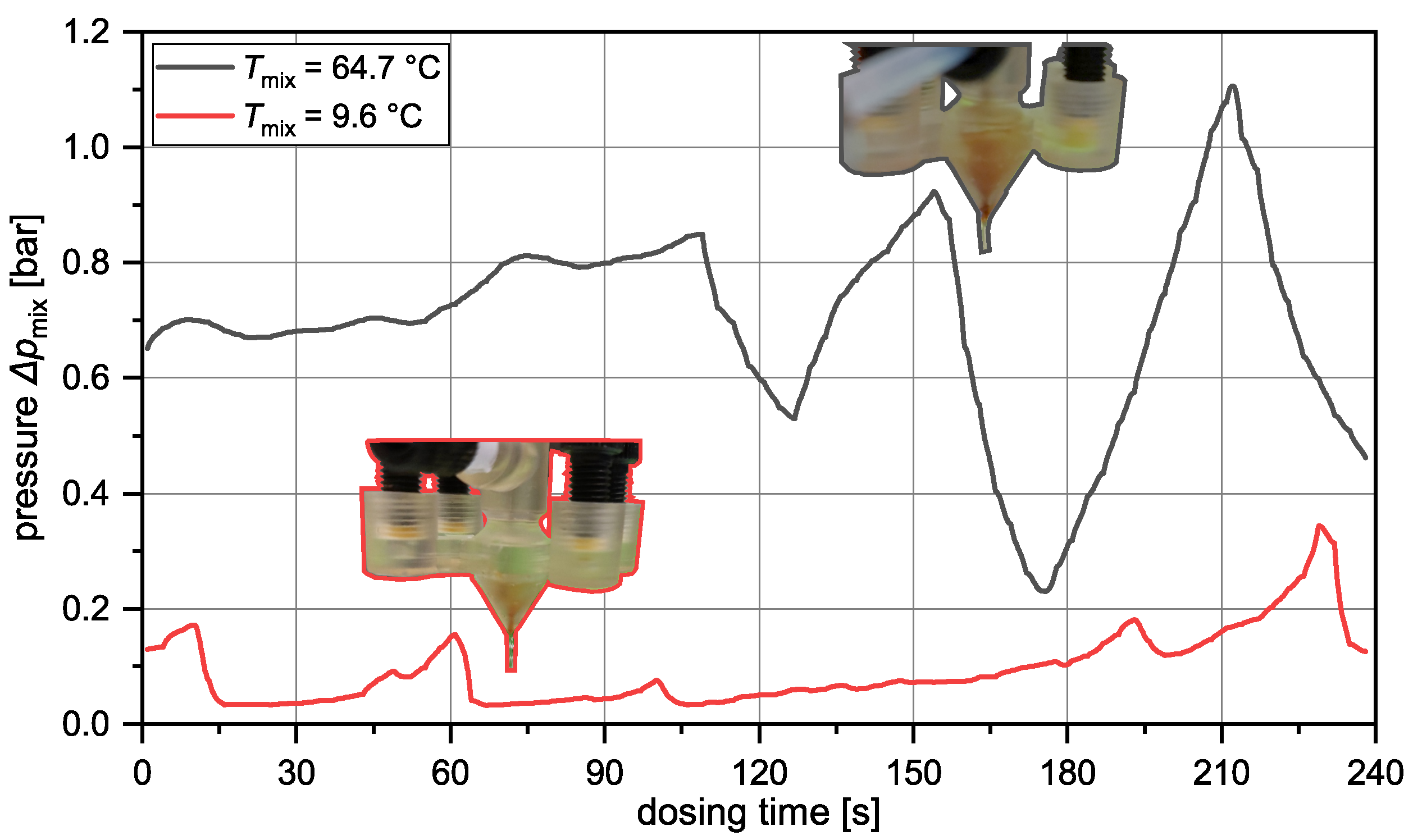
Figure 8.
Images of the mixers P2.0 and P2.1 during operation at the above-mentioned flow conditions.
Figure 8.
Images of the mixers P2.0 and P2.1 during operation at the above-mentioned flow conditions.

Table 1.
History of the mixer designs that were iteratively generated. Changes compared to the preceding prototype are marked in red in the images. For the experimental setup, consider Figure A2.
Table 1.
History of the mixer designs that were iteratively generated. Changes compared to the preceding prototype are marked in red in the images. For the experimental setup, consider Figure A2.
| Prototype | CAD Sketch | Channel Geometry | Changelog * | Remarks |
|---|---|---|---|---|
| P1.0 | 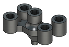 | 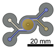 | – | Temperature sensor from above |
| P1.1 | 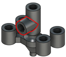 | 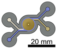 | Pressure sensor connector added | Pressure sensor from the side |
| P1.2 |  | 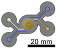 | Pointed outlet, sharp outlet rim to avoid solid adhesion | – |
| P2.0 |  |  | Tangential merging of fluid streams to maintain flow profile | Most successful in operation |
| P2.1 |  |  | Larger mixing chamber ( = 10 mm to = 14 mm) | Mixing chamber not filling up |
* Compared to the previous prototype.
Table 2.
Compositions of the used reactant solutions. For the continuous operation mode, 4 inlet streams were used (, ). For the batch reference, two reactant solutions were mixed ().
Table 2.
Compositions of the used reactant solutions. For the continuous operation mode, 4 inlet streams were used (, ). For the batch reference, two reactant solutions were mixed ().
| Conditions | ||||||
|---|---|---|---|---|---|---|
| Batch Reference | 0.8 mol·L−1 | 0.3 mol·L−1 | 0.1 mol·L−1 | 50 mL | – | 100 mL |
| Continuous Set A (5 min) | 1.6 mol·L−1 | 0.6 mol·L−1 | 0.2 mol·L−1 | 5 mL·min−1 | 5 mL·min−1 | 100 mL |
| Continuous Set B (4 min) | 2 mol·L−1 | 0.75 mol·L−1 | 0.25 mol·L−1 | 5 mL·min−1 | 7.5 mL·min−1 | 100 mL |
Disclaimer/Publisher’s Note: The statements, opinions and data contained in all publications are solely those of the individual author(s) and contributor(s) and not of MDPI and/or the editor(s). MDPI and/or the editor(s) disclaim responsibility for any injury to people or property resulting from any ideas, methods, instructions or products referred to in the content. |
© 2024 by the authors. Licensee MDPI, Basel, Switzerland. This article is an open access article distributed under the terms and conditions of the Creative Commons Attribution (CC BY) license (https://creativecommons.org/licenses/by/4.0/).
Share and Cite
MDPI and ACS Style
Höving, S.; Ronnewinkel, P.; Kockmann, N. From Batch to Continuous Small-Scale Production of Particles: Mixer Design Methodology for Robust Operation. Crystals 2024, 14, 398. https://doi.org/10.3390/cryst14050398
AMA Style
Höving S, Ronnewinkel P, Kockmann N. From Batch to Continuous Small-Scale Production of Particles: Mixer Design Methodology for Robust Operation. Crystals. 2024; 14(5):398. https://doi.org/10.3390/cryst14050398
Chicago/Turabian StyleHöving, Stefan, Philipp Ronnewinkel, and Norbert Kockmann. 2024. "From Batch to Continuous Small-Scale Production of Particles: Mixer Design Methodology for Robust Operation" Crystals 14, no. 5: 398. https://doi.org/10.3390/cryst14050398
Note that from the first issue of 2016, this journal uses article numbers instead of page numbers. See further details here.