
Influence of MACl on the Crystallization Kinetics of Perovskite via a Two-Step Method
by
 , and
, and
Chenyue Wang
1,2,3,†,
Bingchen He
1,2,†,
Meirong Fu
1,2,3,†,
Zhenhuang Su
1,2,*,
Liujiang Zhang
1,2,3,
Junhan Zhang
1,2,3,
Bingbao Mei
1,2,* and
Xingyu Gao
1,2,* 1
Shanghai Institute of Applied Physics, Chinese Academy of Sciences, 2019 Jia Luo Road, Shanghai 201800, China
2
Shanghai Synchrotron Radiation Facility (SSRF), Shanghai Advanced Research Institute, Chinese Academy of Sciences, 99 Haike Road, Shanghai 201204, China
3
University of Chinese Academy of Sciences, 19A Yuquan Road, Beijing 100049, China
*
Authors to whom correspondence should be addressed.
†
These authors contributed equally to this work.
Crystals 2024, 14(5), 399; https://doi.org/10.3390/cryst14050399
Submission received: 1 April 2024
/
Revised: 9 April 2024
/
Accepted: 21 April 2024
/
Published: 25 April 2024
(This article belongs to the Special Issue Progress and Prospects of Perovskite Films)
Abstract
:The addition of methylammonium chloride (MACl) significantly improves the performance and stability of perovskite fabricated by two-step processes. However, its role in crystallization dynamics has not been thoroughly studied. In this work, a comparison study is carried out using different additions of MACl to investigate the impact of the perovskite crystallization dynamics. In situ grazing incidence wide-angle X-ray scattering (GIWAXS) observations during the annealing process of perovskite revealed that the amount of MACl significantly influences the crystallinity and orientation of the perovskite. Increasing the MACl addition enhances the crystallinity of the perovskite in the wet film‘s intermediate phase and strengthens the out-of-plane orientation of the FAPbI3 perovskite α-phase (001) planes during annealing. Moreover, it was found that both excessive and insufficient amounts of MACl introduce defects into the perovskite, which are detrimental to device performance. In contrast, an optimal ratio of MACl-9 mg leads to the formation of uniform and large-grained FAPbI3 perovskite films, with the longest carrier lifetimes (163.7 ns) compared to MACl-5 mg (68.4 ns) and MACl- 13 mg (120.1 ns). As a result, the fabricated MACl-9 mg-based solar cell achieved the highest efficiency (22.63%), which is higher than those of MACl-5 mg (21.47%) and MACl-13 mg (20.07%).
1. Introduction
In the rapidly evolving field of optoelectronics, halide perovskite materials have emerged as an ideal choice for the fabrication of low-cost, high-performance photovoltaic devices due to their unique optoelectronic properties. These include low formation energy, a tunable band structure and bandgap width, a high light absorption coefficient, and a long carrier diffusion length [1,2,3]. The development trajectory of these materials is emblematically reflected in the explosive growth of power conversion efficiency (PCE), which has seen a breakthrough, increasing to over 26% within just a decade [4,5,6,7,8], nearing the current conversion efficiency of crystalline silicon cells, marking them as representatives of the next-generation photovoltaic materials. They demonstrate immense potential in fields such as photovoltaic cells and optoelectronic devices.
Perovskite absorber layers can be fabricated through various methods, including one-step spin-coating, two-step spin-coating, blade coating, and vapor deposition techniques. Among these, the two-step spin-coating method, pioneered by Grätzel et al. in 2013, which achieved the highest certified perovskite solar cell (PSC) efficiency of 14.1% in that year [9], has been widely adopted for the fabrication of perovskite films due to its simplicity, good reproducibility, and high film quality. To date, the two-step method has consistently achieved the highest PCE certifications reported by the National Renewable Energy Laboratory (NREL) chart, with the current PCE reaching 26.0% [6,8,10,11]. This method involves depositing a lead halide precursor layer first, followed by its conversion into perovskite through immersion or spin-coating with an organic halide amine salt solution. However, it also faces challenges like the formation of intermediate phases and incomplete precursor conversion, which can lead to film unevenness and degrade the crystal quality of perovskite films.
In this context, MACl is a common additive in solution-processed perovskites, acting as a Lewis acid coordinating with lead ions and promoting the conversion of the intermediate phase. It not only participates in the perovskite structure as an internal ion but also influences the crystallization kinetics of perovskite crystals, fostering the formation of higher-quality films, and thereby enhancing device performance and stability. The addition of MACl has been proven to effectively regulate and optimize the crystallization of perovskites in the two-step method, particularly for FAPbI3 perovskites. They have an ideal optical bandgap and are stable in a yellow non-perovskite hexagonal phase (δ-phase) at room temperature. Their phase transition to the black cubic perovskite phase (α-phase) occurs at approximately 150 °C [12]; MACl can specifically optimize its crystallization pathway. The dual nature of MACl, with MA+ ions aiding perovskite crystallization and Cl− ions being volatile, allows MA-based additives to rapidly induce the formation of MA-rich nuclei for pure α-phase FAPbI3, lowering the formation energy of the FAPbI3 α-phase and, thus, reducing the phase transition temperature to near-room temperature [13]. Consequently, this suppresses the δ-phase and enhances the α-phase of FAPbI3. However, the introduction of MA affects the chemical compositional purity of FAPbI3, as the incorporation of MAI and MABr leads to their stabilization within the perovskite lattice, resulting in an increased bandgap and deviation from the Shockley–Queisser limit, thereby reducing the corresponding solar cell device’s PCE. Meanwhile, compounds of Cl with amines typically exhibit lower volatilization temperatures. Therefore, the volatile nature of MACl plays a unique role in promoting perovskite crystallization during the annealing process [14], optimizing crystallinity, suppressing defects and impurities, and ensuring the phase purity of α-phase FAPbI3. Additionally, the volatilization of MACl during annealing leads to lattice restructuring, resulting in secondary crystallization of the perovskite film [15], which increases grain size, reduces surface roughness [16,17,18], and improves carrier transport [19]. The addition of MACl has also been shown to induce the reorientation of grains. For example, depositing MACl on top of MAPbI3 results in a change in the orientation of cubic phase MAPbI3 toward the (100) direction during annealing, ultimately converting to a tetragonal perovskite phase with (110) plane orientation, thereby improving PSC performance [15]. Moreover, MACl can slow down the perovskite crystal formation process, allowing strain release during grain growth [18,20]. On the other hand, the addition of MACl can lead to non-stoichiometry in the perovskite film, resulting in the formation of halogen vacancy defects due to the asynchronous volatilization of methylammonium cations and chloride ions [21]. Therefore, controlling the amount of MACl added is crucial to the current high-performance two-step method process. The crystallization kinetics and thermodynamics of MACl’s role in perovskites remain unclear, and research on the crystal structure dynamics under different concentration additions is still lacking.
Herein, we systematically studied the impact of MACl addition on FAPbI3 perovskite films prepared via the two-step method. Based on the commonly used amounts of MACl, we divided the MACl concentration into three groups: 5 mg, 9 mg, and 13 mg, added to 1 mL of IPA solution. GIWAXS is particularly suitable for in situ observation of the crystallization process of perovskite films during spin-coating and annealing [22,23,24,25,26,27]. The MACl addition significantly affects the crystallinity and orientation of perovskites. Increasing the amount of MACl added enhances the crystallinity of the perovskite in both intermediate-phase wet films and fabricated perovskite films. Additionally, we found that increasing the concentration of MACl enhances the (001) orientation of the perovskite. Furthermore, the MACl-9 mg addition enhances large-grained and uniform FAPbI3 perovskite films. Meanwhile, the film with the MACl-9 mg addition has the highest PL intensity and longest carrier lifetime. As a result, the MACl-9 mg-based solar cell device achieves the highest efficiency of 22.63%, which is higher than those of MACl-5 mg (21.47%)- based and MACl-13 mg (20.07%)-based solar cell devices.
2. Materials and Experimental
2.1. Materials
Lead iodide was purchased from TCI (Tokyo Chemical Industry, Tokyo, Japan). Cesium iodide (CsI), formamidinium iodide (FAI), methylammonium chloride (MACl), and 2,2′,7,7′-tetrakis(N,N-di-p-methoxy-phenylamine)-9,9′-spirobifluorene (Spiro-OMeTAD) were purchased from Xi’an Yuri Solar Co. Ltd. (Xi’an, China) 4-tert-butylpyridine (tBP), bis (trifluoromethylsulfonyl)-imide lithium salt (Li-TFSI), chlorobenzene (CB), acetonitrile (ACN), N,N-dimethylformamide (DMF), dimethylsulfoxide (DMSO), and isopropyl alcohol (IPA) were purchased from Sigma-Aldrich. Indium tin oxide (ITO) glass was purchased from Advanced Election Technology CO. Ltd (Shenzhen, China).
2.2. Device Fabrication
A total of 30 μL of SnO2 precursor solution was drop-casted onto an ITO glass substrate, followed by spin-coating at 3000 rpm with an acceleration of 3000 rpm/s for 30 s. The substrate was then heated at 150 °C for 30 min to form the SnO2 transport layer. Prior to depositing the perovskite active layer, the ITO substrates with SnO2 were treated in a UV ozone cleaner for 15 min. Then, 35 μL of PbI2 solution (691.5 mg PbI2 and 19.5 mg CsI in the mixed solvent of 900 μL DMF and 100 μL DMSO) was spin-coated onto the SnO2 layer surface, followed by spin-coating at 2000 rpm for 30 s to form a PbI2 precursor film. The resultant film was then heated at 70 °C for 1 min. Afterward, 70 μL of organic solution (90 mg FAI and 5–13 mg MACl in 1 mL IPA) was spin-coated at 2300 rpm for 30 s to form an intermediate phase film of perovskite. Finally, the film was thermally annealed in an environment with relative humidity of 30–50% at 150 °C for 15 min to obtain perovskite films. Spiro-OMeTAD was used as the hole transport material in this study. A 35 μL solution of Spiro-OMeTAD in CB (adding 30 μL TBP and 17.5 μL Li-TFSI solution (520 mg/mL in ACN)) was spin-coated at 3000 rpm for 30 s to form the hole transport layer. A gold (Au) electrode approximately 100 nm thick was deposited on the hole transport layer using vacuum thermal evaporation technology.
2.3. Device Characterization
Scanning electron microscopy (SEM) images were measured by a Sigma 300 (ZEISS, Oberkochen, Germany). The photoluminescence spectrum and time-resolved photoluminescence (TRPL) were assessed using a FluoroMax+ of Horiba. The current–voltage (J-V) curves of the PSC were measured by a Keithley 2400 source meter under AM 1.5 G solar irradiation at 100 mW/cm2, with a mask defining a device area of 0.075 cm2. The in situ GIWAXS measurements were conducted in the BL14B1 beamline of the Shanghai Synchrotron Radiation Facility (SSRF) (Shanghai, China), and the testing X-ray wavelength was 1.24 Å. The incident angle for each simple was 0.5°. The exposure time for each image was 5 s. All the perovskites were heated at 150 °C for in situ GIWAXS measurements.
3. Results
In the two-step fabrication process of perovskite thin films, the absence of MACl results in inferior film quality, characterized by random orientation and poor crystallinity, a higher proportion of non-perovskite yellow phases, and smaller grain sizes. Therefore, the addition of MACl is essential as it plays a crucial role in assisting crystallization. Considering the typical concentrations of MACl used in the two-step method, we investigated FAPbI3 perovskites by introducing three different concentrations of MACl: 5 mg, 9 mg, and 13 mg (dissolved in 1 mL IPA solution). FA-based perovskites, which are currently the leading A-site cations in high-efficiency perovskite formulations, have a large ionic radius (approximately 253 pm) that results in a higher tolerance factor of the perovskite structure, making them prone to phase transitions into a non-optically-active hexagonal phase, also known as the yellow δ-phase, at room temperature. Therefore, we enhanced the stability α-FAPbI3 phase by introducing CsI with a molar ratio of 0.05 with respect to PbI2, to achieve a stable cubic lattice structure [24,28,29]. This study employed a commonly used annealing temperature of 150 °C for the two-step method, which was instrumental in achieving optimal conditions for the crystallization process, balancing between transforming the perovskite to its optically active phase, minimizing crystal defects through the effective evaporation of additives, and preventing decomposition of the material [12,17,30]. Environmental humidity significantly affects the properties of perovskites [31]. For the two-step preparation process of perovskite films, appropriate humidity control aids in enhancing the diffusion of organic salts within the film, leading to a more uniform film [32,33]. We maintained the environmental humidity within the range of 30–50% RH.
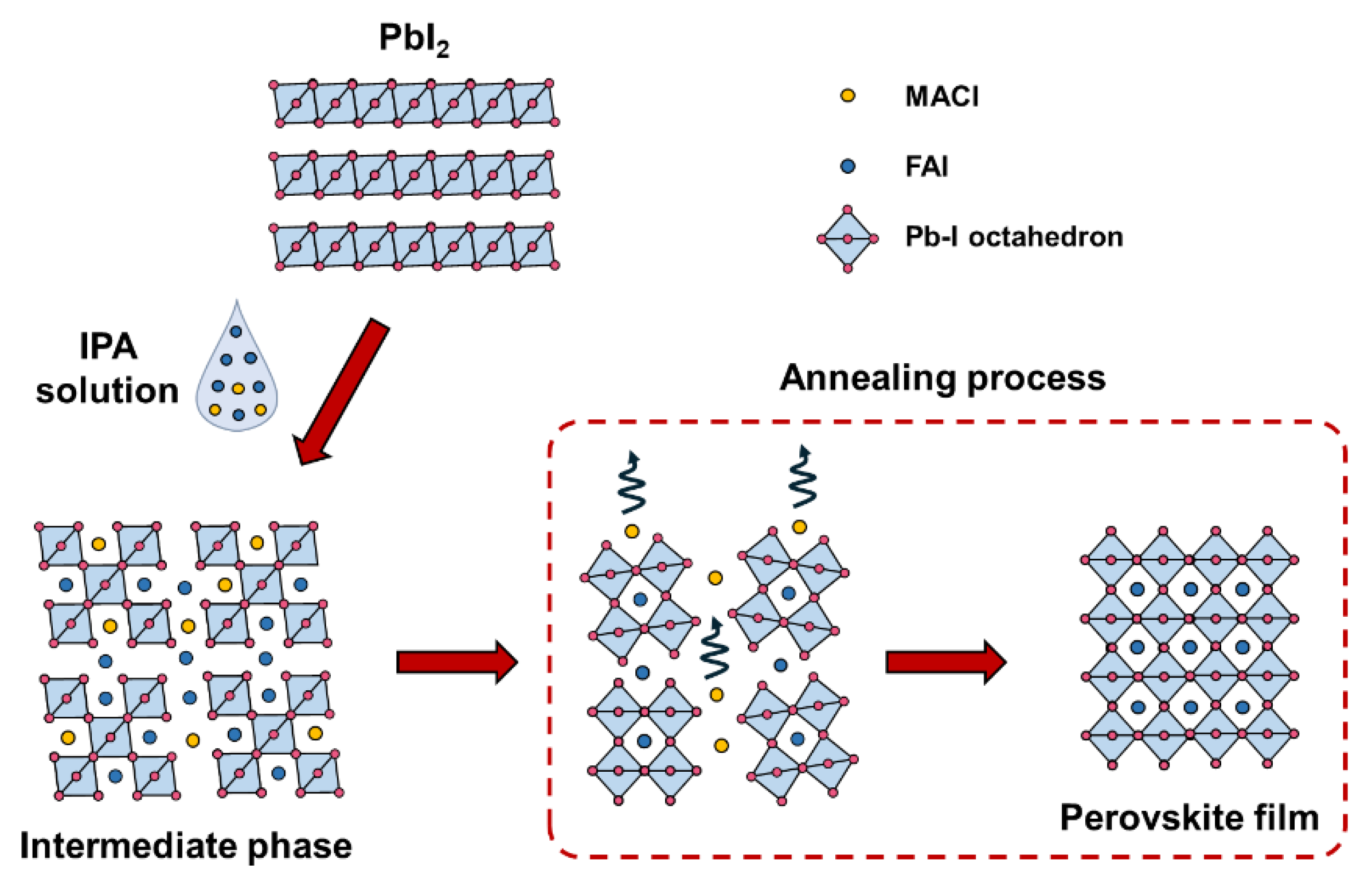
Synchrotron-based GIWAXS serves as a powerful tool for exploring the crystallization dynamics of perovskites, owing to its large photon flux, high signal sensitivity and signal-to-noise ratio, as well as its spatial–temporal resolution. Utilizing GIWAXS, we conducted in situ studies of the crystallization process of perovskites via a two-step method. The annealing of two-step perovskite and the in situ GIWAXS measurement schematic are illustrated in Figure 1. Perovskite films were prepared using an intermolecular exchange strategy of the two-step method, where a layer of organic amine salt in the IPA solution was spin-coated onto a lead iodide intermediate phase thin film inside a glove box, forming a wet perovskite intermediate phase film. This sample was then transferred to a GIWAXS experimental setup for annealing, where X-rays were applied and a 2D diffraction pattern of the film was collected using a MarCCD 225 flat panel detector. An X-ray incidence angle of 0.5°, exceeding the perovskite’s total reflection angle (approximately 0.18°) and allowing penetration depths greater than 100 nm [7], enabled the acquisition of structural information from the bulk of the film. The annealing process of samples with three different MACl concentrations was analyzed at three time points: the beginning (0 s), early stage (60 s), and mature stage (420 s) of annealing, as shown in Figure 2. For a more precise quantitative analysis of the crystallinity and grain orientation of the perovskites, the 2D diffraction patterns of the three samples at different time points were integrated using fit2d software (V12.077), resulting in corresponding 1D diffraction spectra and the distribution spectra of the intensity of the perovskite (001) planes, presented in Figure 3a–c and d–f, respectively.
From Figure 2a–i, we observe that across all three MACl concentration levels, the film samples throughout the annealing process exhibit typical perovskite α-phases, generating annular diffraction peaks in q-space at 10 nm−1, 14.2 nm−1, 17.3 nm−1, and 20 nm−1. Utilizing the formula d = 2π/q, the interplanar spacings, d, are calculated as 6.3 Å, 4.4 Å, 3.6 Å, and 3.1 Å, corresponding to the (001), (110), (111), and (002) planes of the FAPbI3 perovskite cubic lattice, respectively. Based on the GIWAXS 2D images for the sample with a lower addition of 5 mg of MACl, Figure 2a reveals the presence of a visible diffraction ring near q = 8.5 nm−1, corresponding to the δ-phase of FAPbI3. The calculated intensity of the δ diffraction peak is 59.3, as seen in Figure 3a, which represents 56% of the intensity (105) of the α-phase (001) peak. In contrast, samples with 9 mg and 13 mg MACl additions, as shown in Figure 2d,g, exhibit no visible δ-phase. Figure 3b,c demonstrate an almost nonexistent diffraction intensity for the δ-phase. At the onset of annealing, the samples had just undergone a second organic salt spin-coating step on a lead iodide thin film, maintaining a wet intermediate phase of the perovskite. Studies suggest that MACl participates in the formation of the low-energy α-phase of the perovskite in the wet film state, thereby inhibiting its transition to the δ-phase. Our research further indicates that the suppression of the δ-phase by MACl is concentration-dependent, requiring a certain threshold amount to completely inhibit the detrimental δ-phase. Compared to FAI, the addition of MACl needs to be at least 5 mg to approach the threshold for complete conversion of the yellow phase, likely related to the stoichiometric ratio of the intermediate phase formed between MACl, FAI, and PbI2. After 60 s of annealing, even for the sample with the lowest MACl concentration of 5 mg, the δ-phase disappears, indicating that at higher temperatures (150 °C), FAPbI3 overcomes the transition energy barrier, transforming from the δ-phase to the more structurally symmetrical α-phase. Thermodynamically, while all samples almost exclusively exhibit pure α-phase perovskite at the 60 s annealing time point, the kinetic pathway of film crystallization still affects the overall crystalline quality. The initial transition from the δ-phase to the α-phase can induce defects due to the rapid structural change from δ-FAPbI3 to α-FAPbI3, involving ionic movement between adjacent [PbI6]4− octahedra [14], potentially leading to stacking faults during the transition [34]. In terms of crystallinity, at the same annealing time points, an increasing trend in the intensity of α-phase perovskite peaks is observed with higher MACl concentrations, highlighting the most significant difference in crystallinity during the early stages of annealing.
Furthermore, in the 2D images corresponding to the late stage of annealing for the three conditions, labeled in Figure 2c,f,i, diffraction signals of varying intensities are observed at around q = 9 nm−1, associated with the (001) peak of lead iodide (PbI2). Notably, at the annealing time of 420 s, the sample with 5 mg of MACl addition exhibits a pronounced PbI2 signal with a peak intensity of 14.6; for the samples with 9 mg and 13 mg of MACl addition, the corresponding PbI2 diffraction peak intensities are reduced to 6.8 and 3.5, respectively. This phenomenon indicates that—with increasing amounts of MACl added—the quantity of lead iodide in the films correspondingly decreases. This trend is closely linked to the role of MACl in the formation process of perovskites, where MACl acts as a facilitator for perovskite formation. Due to its lower decomposition temperature, MACl volatilizes and escapes from the perovskite lattice during the annealing process [16,35], yet remains to some extent after the limited annealing time [36]. This retention can be attributed to the increased crystallinity and more densely packed grains within the perovskite solid films during the later stages of annealing, which hinders further diffusion of MACl within the perovskite films. Increasing the addition of MACl leads to a greater residual amount of MACl in the perovskite films after annealing, thereby reducing the quantity of lead iodide formed from perovskite decomposition.
In orientation, the α-FAPbI3 (001) planes of all three samples predominantly exhibit orientations at 36°/144° at the start of annealing (as shown in Figure 2a,d,g). This specific orientation originates from the unique fabrication process of the two-step method. In the first stage of this method, a lead iodide intermediate phase is formed, with the layers of lead iodide being occupied by dimethyl sulfoxide (DMSO) solvent molecules. In the subsequent step, organic amine salts are introduced and deposited on the lead iodide layers. This not only replaces the interlayer DMSO molecules but also reacts rapidly with PbI2, directly generating the perovskite structure on the existing lead iodide framework. Because this intercalation reaction occurs directly on the original lead iodide framework, the perovskite formed through the two-step method inherits the orientation of the [PbI6]4− octahedra in the original lead iodide framework. This results in the α-phase FAPbI3 perovskite displaying a specific (001) plane orientation at 36° [19,37,38,39,40], also referred to as the (111) orientation (since the 36° angle of the (001) plane corresponds to the out-of-plane orientation of the (111) plane [41]). At an annealing time of 60 s, only the sample with 13 mg of MACl addition begins to exhibit a 90° orientation, and by the annealing time of 420 s, a clear 90° orientation is observed in samples under all conditions, with its intensity increasing with the amount of MACl added. Specifically, the 90° orientation peak intensities for samples with 5 mg, 9 mg, and 13 mg of MACl are 54.9, 97.5, and 183.8 (as seen in Figure 3d–f), respectively, with their orientation intensity ratios being 1:1.8:3.3, closely matching their MACl addition ratios of 1:1.8:2.6. This phenomenon indicates that the amount of MACl added is the dominant factor affecting the formation of the perovskite (001) 90° orientation, likely due to the secondary crystallization induced by the MACl addition, leading to a change in grain orientation [17]. Furthermore, we find that the GIWAXS 2D images corresponding to 420 s of annealing time for films under the three conditions (Figure 2c,f,i), compared to the early annealing diffraction patterns (Figure 2a,d,g), show more discrete and larger bright spots in the diffraction rings. Therefore, the integrated intensity variation curves with azimuthal angles (the blue lines in Figure 3d,e,f) exhibit more fluctuations, reflecting the growth of internal grains within the perovskite films as annealing progresses.
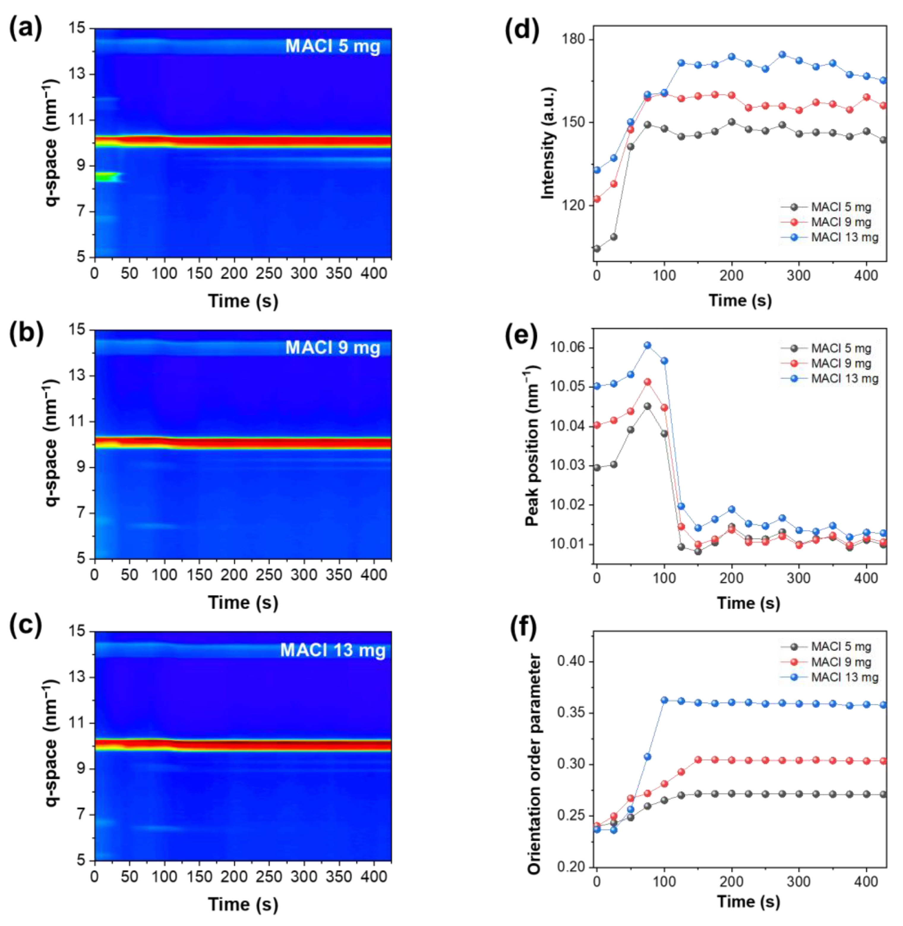
To observe the entire process of perovskite film annealing and crystallization, we integrate all images, and the calculated one-dimensional diffraction spectra as a function of annealing time were plotted in contour maps. The maps, shown in Figure 4a–c, use a rainbow color spectrum to correspond to diffraction intensities. The color bar on the right side of the figures indicates intensity values, with purple representing low intensity and red high intensity. Consistent with the conclusions drawn from Figure 3a–c, all samples exhibit considerable intensity of the α-phase FAPbI3 (001) peak from the beginning of annealing, a distinctive feature from the one-step method due to the intercalation effect inherent in the two-step process, which yields significant crystallinity immediately after spin-coating [24,42,43]. The variation in peak intensity for the three samples diminishes after 150 s, gradually stabilizing. To quantitatively study perovskite crystallization, we plot the intensity of the FAPbI3 (001) peak value over time in a line graph, as shown in Figure 4d. At the start of annealing, the perovskite (001) peak intensities for samples with 5 mg, 9 mg, and 13 mg of MACl are 104.5, 122.5, and 132.9, respectively, with ratios of 1:1.17:1.27. By 420 s, the peak intensities for the three samples are 143.7, 156.1, and 165.2, with ratios of 1:1.09:1.15, indicating the greatest disparity in crystallinity among the samples in the early stages of annealing, and the 5 mg MACl addition exhibits the lowest crystallinity. However, as the annealing time increases, the difference in crystallinity relative to the other two groups gradually decreases, as MACl promotes the initial formation of perovskite in the wet film‘s intermediate phase, and the reaction extent is positively correlated with the amount of MACl added, whereas the later stage of the reaction is mainly dependent on temperature. We observed the most significant change in perovskite crystallinity for the sample with 5 mg of MACl between 25 s and 50 s (Figure 4d), a period during which the δ-phase of FAPbI3 disappears, indicating high temperatures facilitate the transition from the δ-phase to the α-phase. Then, at 75 s, its crystalline intensity reaches a stable phase. For samples with 9 mg and 13 mg of MACl, not only does the peak value of perovskite increase with the amount of MACl added, but the time to reach stable crystallization also differs, arriving at stable crystallization points at 100 s and 125 s, respectively, possibly due to greater degrees of secondary crystallization caused by the increased amount of MACl. However, the crystalline intensity of the sample with 13 mg of MACl decreases after 300 s, potentially due to excessive MACl participating in crystallization and then volatilizing in large amounts during annealing, leading to a reduction in perovskite crystallinity [17]. The positions of the α-phase (001) peaks for the three samples are also statistically analyzed, as shown in Figure 4e, where three processes in the peak position change during annealing for samples with 5 mg, 9 mg, and 13 mg of MACl: initially growing within 0–75 s, reaching the highest peak position at 75 s, then rapidly decreasing between 75 s and 125 s, and gradually stabilizing after 150 s, nearing the standard peak position of 10 nm−1 for α-phase FAPbI3. The peak position changes are attributed to the following: the initial phase where solvents like DMSO, DMF, and IPA in the wet film‘s intermediate phase rapidly volatilize; organic amine salts diffuse into PbI2, with MA+ ions reacting first with PbI2 to form perovskite nuclei; the perovskite is predominantly MA-rich at this stage, and has smaller interplanar spacing than pure FA-based perovskite, resulting in a larger diffraction peak position. The diffusion during annealing accelerates the formation of MA-rich nuclei, initially increasing the peak position. In the second phase, as most solvents volatilize and the perovskite solid film forms, perovskite crystalline growth slows down, with FA+ ions rapidly replacing MA+ in the perovskite lattice; the replaced MA+ recombines with Cl− to form MACl and rapidly volatilizes. At this point, the perovskite lattice expands due to the entry of FA+ ions, lowering the peak position. As grain packing becomes denser, MACl volatilization gradually slows down, leading to a relatively stable third phase in the peak position. Figure 4e shows that the peak position shifts for samples with 5 mg, 9 mg, and 13 mg of MACl are 0.05 nm−1, 0.041 nm−1, and 0.034 nm−1, respectively, indicating that samples with higher amounts of MACl exhibit greater ionic exchange extents and, hence, larger peak position changes. Additionally, to quantitatively analyze the changes in perovskite orientation over time, we calculated the orientation order parameter of the α-phase FAPbI3 (001) planes (calculation method based on these studies [44,45]) and plotted the data in Figure 4f. A higher value indicates a higher concentration of the perovskite (001) planes in the 90° orientation. Within the early stage of annealing of all simples, up to 150 s, the (001) orientation gradually forms, with the MACl-13 mg sample showing the most significant increase in the orientation degree (to approximately 0.36 within 100 s); the orientation remains stable thereafter, without further changes. The orientation degrees for the MACl-9 mg and MACl-5 mg samples rise to 0.30 and 0.28, respectively, by 150 s and then stabilize. Similar to changes in the crystalline intensity, increasing the addition of MACl leads to an enhancement of the FAPbI3 (001) orientation. Based on the changes in orientation during the in situ annealing process of perovskites, we illustrate the mechanism in a schematic and present it in Figure 5. During film annealing, the gradual volatilization of MACl leads to secondary crystallization of the perovskite material. The formation and enhancement of this orientation can be attributed to the volatilization of MACl from the perovskite lattice during annealing, causing secondary crystal growth and reconfiguration of the perovskite grains, thereby prompting the crystal orientation to rearrange toward a thermodynamically more stable 90° direction [16,17,35,36,46,47]. Thermodynamically, the 90° orientations of the perovskite (001) planes possess the lowest surface energy [48,49,50]; hence, the grains initially oriented at 36° gradually transition toward the 90° orientation during the early stages of annealing.
To explore the impact of MACl addition on the physical properties of perovskite films, we utilized scanning electron microscopy (SEM) to observe the morphology and grain size distribution of the perovskite’s surface. We found that the sample with 5 mg of MACl addition exhibited smaller grain sizes, with an average diameter of 483.65 nm. The layer of lighter-colored material visible in the images, identified as lead iodide [14], indicates a higher presence of PbI2 on the surface, potentially affecting film stability [8,51]. Conversely, samples with 9 mg and 13 mg of MACl achieve larger average perovskite grain sizes of 843.13 nm and 875.38 nm, respectively, with a relative reduction in PbI2 content on their surfaces. The increase in grain size is attributed to MACl promoting secondary crystal growth of perovskite. However, this effect is limited, constrained by MACl’s role in reducing the formation energy of perovskite; hence, the grain sizes of samples with 9 mg and 13 mg of MACl did not show a significant difference. Nevertheless, for the sample with 13 mg of MACl, we observed black pores within some perovskite grains in the SEM images (Figure 6c). These pores, caused by the excessive escape and volatilization of MACl from the grains, are generally deep and can introduce a significant number of bulk defects, enhancing non-radiative carrier recombination within the film [17]. We evaluated the carrier properties of the perovskite films using steady-state and time-resolved photoluminescence spectroscopy. In PL tests, we observe that the emission peak positions for all three samples are around 800 nm, corresponding to a bandgap of no more than 1.55 eV (considering the potential Stokes shift-induced blue shift in PL testing). In terms of peak intensity, the steady-state PL emission peak intensities for samples with 5 mg, 9 mg, and 13 mg of MACl are in a ratio of 1:4.3:2.7 (as shown in Figure 6e), indicating that peak intensity does not have a straightforward linear relationship with the amount of MACl added; the 9 mg sample corresponds to the highest diffraction peak intensity, proving it has the lowest defect density. For TRPL, we employ a bi-exponential fit to determine the decay of carriers within the perovskite films, with the calculation method for the average carrier lifetime referencing this study [52]. The results indicate that with increasing the MACl addition, the average carrier lifetimes for the samples are 68.4 ns, 163.7 ns, and 120.1 ns, respectively, consistent with the PL results. This suggests there is an optimal amount of MACl addition for assisting perovskite crystallization and reducing defects. When the amount of MACl is excessive, it can lead to excessive escape and volatilization of MACl from within the grains, microscopically creating halide vacancies within the perovskite lattice, and mesoscopically forming voids within the grains [21], thereby damaging the crystal structure. This not only reduces crystalline intensity but also introduces bulk defects, leading to significant non-radiative recombination of electrons and holes, which is detrimental to the carrier transport within the film. The proper addition of MACl-9 mg aids in improving the crystallization of perovskite films, reducing defects, and diminishing the formation of PbI2. It inhibits the excessive production of lead iodide that could catalyze the decomposition of perovskites, as well as potentially induce Schottky defects, leading to ionic migration during the operation of perovskite devices, thereby benefiting long-term stability [8,51]. On the other hand, an excessive amount of MACl can lead to the formation of voids and other bulk defects within the grains, which may serve as decomposition sites, reducing the long-term operational stability of perovskite devices. Moreover, excessive MACl could introduce an abundance of MA+ ion residuals, adversely affecting the thermal stability of perovskite devices.
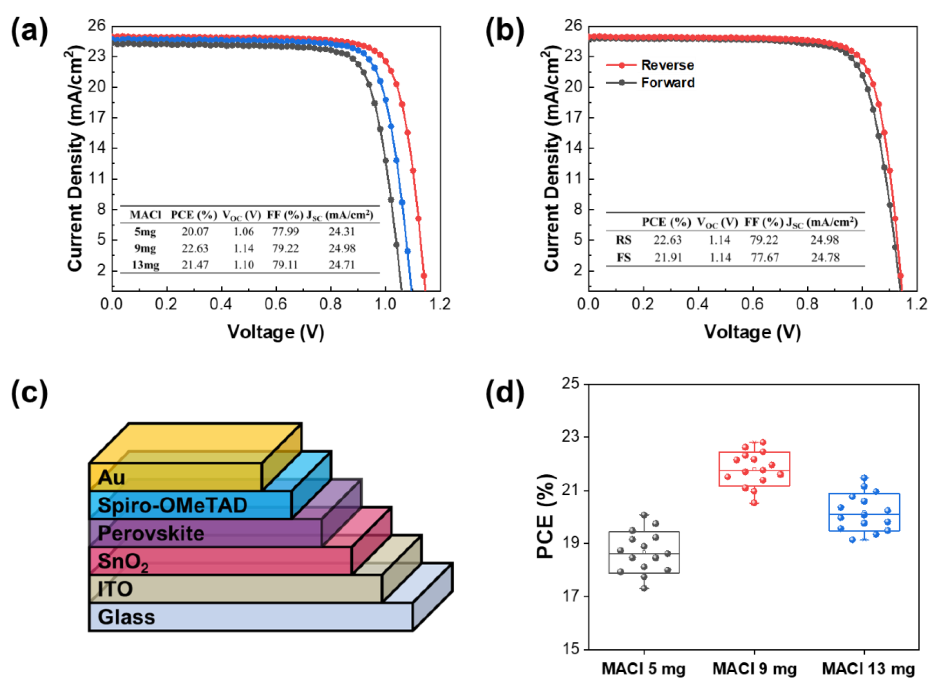
The quality of the perovskite active layer is crucial for ensuring high light absorption and carrier diffusion lengths in perovskite devices, with its preparation process being the most critical aspect of device fabrication. The transition of perovskite from the wet film‘s intermediate phase through thermal treatment for solvent volatilization, nucleation, and crystallization represents the core stages in the preparation of the active layer. The growth mode of perovskite during the annealing process profoundly affects its crystallinity, defect density, and grain orientation, significantly determining device performance [43,53]. To investigate the impact of MACl on device performance, we fabricate PSC devices using perovskite absorber layers with varying amounts of MACl, structured as ITO/SnO2/perovskite/Spiro-OMeTAD/Au, as demonstrated in Figure 7c. The corresponding J-V curves and their parameters are presented in Figure 7a. The champion device with 9 mg of MACl exhibits the highest power conversion efficiency (PCE) at 22.63%, followed by the device with 13 mg of MACl at 21.47%, and the lowest efficiency is observed in the device with 5 mg of MACl at 20.07%. According to the J-V parameters in Figure 7a, the short-circuit current densities (JSC) of the three devices are similar, increasing with the amount of MACl added, respectively, as 24.31 mA/cm2, 24.98 mA/cm2, and 24.71 mA/cm2, with less than 1 mA/cm2 difference between the lowest and highest currents. However, the main improvement in the performance of the MACl-9 mg device is attributed to its open-circuit voltage (VOC) reaching 1.14 V, compared to 1.06 V for the MACl-5 mg device and 1.10 V for the MACl-13 mg device, contributing the most to the increase in device efficiency. This is due to the lowest defect density in the perovskite film with 9 mg of MACl, which is consistent with the results from PL and TRPL spectroscopy, as shown in Figure 6d,e. For the MACl-5 mg sample, its crystallinity is the poorest among the three conditions (Figure 4d), and due to the inferior surface morphology and excessive distribution of lead iodide, carrier transport is severely impaired, leading to a noticeable decrease in VOC and the fill factor (FF). The MACl-13 mg device experiences a performance decline compared to the MACl-9 mg device due to the excessive volatilization of MACl introducing additional defects, mainly manifesting as increased VOC loss. In devices with an optimized addition of 9 mg of MACl, the annealing process effectively mitigates the transition from the δ to α phase and curtails the accumulation of excessive PbI2 in the latter stages [17,51], which significantly diminishes the presence of point defects and preserves a desirable surface morphology. Consequently, this results in a noticeable improvement in VOC and FF. The forward and reverse sweep J-V curves of the MACl-9 mg device are displayed in Figure 7d, showing a small hysteresis with 0.7%, which is almost negligible. The PCE statistical distribution of devices with 5 mg, 9 mg, and 13 mg of MACl is shown in Figure 7d, with average PCE percentages of 18.6%, 21.7%, and 20.1%, respectively, showing greater variance compared to the champion devices, attributed to the broader PCE distribution of devices under the MACl-5 mg and MACl-13 mg conditions.
4. Conclusions
In summary, we prepared FAPbI3 perovskite films through a two-step method and systematically studied the effects of varying MACl concentrations on the structure, morphology, carrier properties, and corresponding device performance. From in situ GIWAXS data, we observed the crystallization kinetics of FAPbI3 perovskite from the intermediate phase of the wet film to the perovskite film during the annealing process influenced by the concentration of MACl additive. We found that MACl can participate in the early nucleation process of perovskite, thereby promoting the formation of the α-FAPbI3 phase, and it also enhances the FAPbI3 (001) orientation during the annealing process. The PL and TRPL measurements revealed that the MACl-9 mg-based film has the highest PL intensity and longest charge combination lifetime (from 68.4 ns to 163.7 ns). As a result, the PCE is improved. The highest PCE of 22.63% is obtained in MACl-9 mg-based devices, which is higher than those of MACl-5 mg (21.47%) and MACl-13 mg (20.07%). These findings not only deepen our understanding of the perovskite’s growth mechanism but also provide significant references for optimizing the preparation process and enhancing the performance of perovskites.
Author Contributions
Conceptualization, C.W., X.G., Z.S. and B.M.; data curation, C.W. and B.H.; formal analysis, C.W., B.H. and L.Z.; funding acquisition, X.G. and B.M.; investigation, C.W., B.H. and Z.S.; methodology, M.F. and J.Z.; project administration, Z.S. and X.G.; resources, X.G.; supervision, X.G. All authors have read and agreed to the published version of the manuscript.
Funding
This work was supported by the Natural Science Foundation of China 12075303, 11675252, U1632265, and Shanghai Science and Technology Development Funds (grant no. 22YF1454500) as well as the Shanghai Pilot Program for Basic Research-Chinese Academy of Science, Shanghai Branch (JCYJ-SHFY-2022-002).
Data Availability Statement
The original contributions presented in the study are included in the article; further inquiries can be directed to the corresponding authors.
Acknowledgments
The authors would thank beamlines BL14B1 and BL03HB at the Shanghai Synchrotron Radiation Facility (SSRF) for providing the beam time. The authors would also thank the User Experiment Assist System of SSRF.
Conflicts of Interest
The authors declare no conflicts of interest.
References
- Steirer, K.X.; Schulz, P.; Teeter, G.; Stevanovic, V.; Yang, M.; Zhu, K.; Berry, J.J. Defect Tolerance in Methylammonium Lead Triiodide Perovskite. ACS Energy Lett. 2016, 1, 360–366. [Google Scholar] [CrossRef]
- Huang, J.; Yuan, Y.; Shao, Y.; Yan, Y. Understanding the physical properties of hybrid perovskites for photovoltaic applications. Nat. Rev. Mater. 2017, 2, 17042. [Google Scholar] [CrossRef]
- Bi, Y.; Hutter, E.M.; Fang, Y.; Dong, Q.; Huang, J.; Savenije, T.J. Charge Carrier Lifetimes Exceeding 15 μs in Methylammonium Lead Iodide Single Crystals. J. Phys. Chem. Lett. 2016, 7, 923–928. [Google Scholar] [CrossRef] [PubMed]
- Kojima, A.; Teshima, K.; Shirai, Y.; Miyasaka, T. Organometal Halide Perovskites as Visible-Light Sensitizers for Photovoltaic Cells. J. Am. Chem. Soc. 2009, 131, 6050–6051. [Google Scholar] [CrossRef] [PubMed]
- Park, N.-G. Perovskite solar cells: An emerging photovoltaic technology. Mater. Today 2015, 18, 65–72. [Google Scholar] [CrossRef]
- Jiang, Q.; Zhao, Y.; Zhang, X.; Yang, X.; Chen, Y.; Chu, Z.; Ye, Q.; Li, X.; Yin, Z.; You, J. Surface passivation of perovskite film for efficient solar cells. Nat. Photonics 2019, 13, 460–466. [Google Scholar] [CrossRef]
- Min, H.; Lee, D.Y.; Kim, J.; Kim, G.; Lee, K.S.; Kim, J.; Paik, M.J.; Kim, Y.K.; Kim, K.S.; Kim, M.G.; et al. Perovskite solar cells with atomically coherent interlayers on SnO2 electrodes. Nature 2021, 598, 444–450. [Google Scholar] [CrossRef] [PubMed]
- Zhao, Y.; Ma, F.; Qu, Z.; Yu, S.; Shen, T.; Deng, H.-X.; Chu, X.; Peng, X.; Yuan, Y.; Zhang, X.; et al. Inactive (PbI2)2RbCl stabilizes perovskite films for efficient solar cells. Science 2022, 377, 531–534. [Google Scholar] [CrossRef]
- Burschka, J.; Pellet, N.; Moon, S.-J.; Humphry-Baker, R.; Gao, P.; Nazeeruddin, M.K.; Grätzel, M. Sequential deposition as a route to high-performance perovskite-sensitized solar cells. Nature 2013, 499, 316–319. [Google Scholar] [CrossRef]
- Yang, W.S.; Noh, J.H.; Jeon, N.J.; Kim, Y.C.; Ryu, S.; Seo, J.; Seok, S.I. High-performance photovoltaic perovskite layers fabricated through intramolecular exchange. Science 2015, 348, 1234–1237. [Google Scholar] [CrossRef]
- Saliba, M.; Matsui, T.; Seo, J.-Y.; Domanski, K.; Correa-Baena, J.-P.; Nazeeruddin, M.K.; Zakeeruddin, S.M.; Tress, W.; Abate, A.; Hagfeldt, A.; et al. Cesium-containing triple cation perovskite solar cells: Improved stability, reproducibility and high efficiency. Energy Environ. Sci. 2016, 9, 1989–1997. [Google Scholar] [CrossRef] [PubMed]
- Zhou, N.; Shen, Y.; Zhang, Y.; Xu, Z.; Zheng, G.; Li, L.; Chen, Q.; Zhou, H. CsI Pre-Intercalation in the Inorganic Framework for Efficient and Stable FA1−x CsxPbI3(Cl) Perovskite Solar Cells. Small 2017, 13, 1700484. [Google Scholar] [CrossRef] [PubMed]
- Su, Z.; Wang, C.; Zheng, G.; Gao, X. Impacts of MAPbBr3 Additive on Crystallization Kinetics of FAPbI3 Perovskite for High Performance Solar Cells. Coatings 2021, 11, 545. [Google Scholar] [CrossRef]
- Bi, L.; Fu, Q.; Zeng, Z.; Wang, Y.; Lin, F.R.; Cheng, Y.; Yip, H.-L.; Tsang, S.W.; Jen, A.K.Y. Deciphering the Roles of MA-Based Volatile Additives for α-FAPbI3 to Enable Efficient Inverted Perovskite Solar Cells. J. Am. Chem. Soc. 2023, 145, 5920–5929. [Google Scholar] [CrossRef] [PubMed]
- Liu, X.; Guo, Y.; Cheng, Y.; Lu, S.; Li, R.; Chen, J. Advances in chloride additives for high-efficiency perovskite solar cells: Multiple points of view. Chem. Commun. 2023, 59, 13394–13405. [Google Scholar] [CrossRef] [PubMed]
- Mu, C.; Pan, J.; Feng, S.; Li, Q.; Xu, D. Quantitative Doping of Chlorine in Formamidinium Lead Trihalide (FAPbI3−xClx) for Planar Heterojunction Perovskite Solar Cells. Adv. Energy Mater. 2017, 7, 1601297. [Google Scholar] [CrossRef]
- Chang, J.; Feng, E.; Li, H.; Ding, Y.; Long, C.; Gao, Y.; Yang, Y.; Yi, C.; Zheng, Z.; Yang, J. Crystallization and Orientation Modulation Enable Highly Efficient Doctor-Bladed Perovskite Solar Cells. Nano-Micro Lett. 2023, 15, 164. [Google Scholar] [CrossRef] [PubMed]
- Chen, B.; Yu, Z.; Liu, K.; Zheng, X.; Liu, Y.; Shi, J.; Spronk, D.; Rudd, P.N.; Holman, Z.; Huang, J. Grain Engineering for Perovskite/Silicon Monolithic Tandem Solar Cells with Efficiency of 25.4%. Joule 2019, 3, 177–190. [Google Scholar] [CrossRef]
- Meng, K.; Wang, X.; Xu, Q.; Li, Z.; Liu, Z.; Wu, L.; Hu, Y.; Liu, N.; Chen, G. In Situ Observation of Crystallization Dynamics and Grain Orientation in Sequential Deposition of Metal Halide Perovskites. Adv. Funct. Mater. 2019, 29, 1902319. [Google Scholar] [CrossRef]
- Bush, K.A.; Rolston, N.; Gold-Parker, A.; Manzoor, S.; Hausele, J.; Yu, Z.J.; Raiford, J.A.; Cheacharoen, R.; Holman, Z.C.; Toney, M.F.; et al. Controlling Thin-Film Stress and Wrinkling during Perovskite Film Formation. ACS Energy Lett. 2018, 3, 1225–1232. [Google Scholar] [CrossRef]
- Liu, Z.; Liu, T.; Li, M.; He, T.; Guo, G.; Liu, P.; Chen, T.; Yang, J.; Qin, C.; Dai, X.; et al. Eliminating Halogen Vacancies Enables Efficient MACL-Assisted Formamidine Perovskite Solar Cells. Adv. Sci. 2024, 11, 2306280. [Google Scholar] [CrossRef]
- Li, G.; Su, Z.; Canil, L.; Hughes, D.; Aldamasy, M.H.; Dagar, J.; Trofimov, S.; Wang, L.; Zuo, W.; Jerónimo-Rendon, J.J.; et al. Highly efficient p-i-n perovskite solar cells that endure temperature variations. Science 2023, 379, 399–403. [Google Scholar] [CrossRef] [PubMed]
- Wang, C.; Zuo, C.; Chen, Q.; Ding, L. GIWAXS: A powerful tool for perovskite photovoltaics. J. Semicond. 2021, 42, 060201. [Google Scholar] [CrossRef]
- Qin, M.; Chan, P.F.; Lu, X. A Systematic Review of Metal Halide Perovskite Crystallization and Film Formation Mechanism Unveiled by In Situ GIWAXS. Adv. Mater. 2021, 33, 2105290. [Google Scholar] [CrossRef] [PubMed]
- Steele, J.A.; Solano, E.; Hardy, D.; Dayton, D.; Ladd, D.; White, K.; Chen, P.; Hou, J.; Huang, H.; Saha, R.A.; et al. How to GIWAXS: Grazing Incidence Wide Angle X-ray Scattering Applied to Metal Halide Perovskite Thin Films. Adv. Energy Mater. 2023, 13, 2300760. [Google Scholar] [CrossRef]
- Park, J.; Kim, J.; Yun, H.-S.; Paik, M.J.; Noh, E.; Mun, H.J.; Kim, M.G.; Shin, T.J.; Seok, S.I. Controlled growth of perovskite layers with volatile alkylammonium chlorides. Nature 2023, 616, 724–730. [Google Scholar] [CrossRef]
- Shi, P.; Ding, Y.; Ding, B.; Xing, Q.; Kodalle, T.; Sutter-Fella, C.M.; Yavuz, I.; Yao, C.; Fan, W.; Xu, J.; et al. Oriented nucleation in formamidinium perovskite for photovoltaics. Nature 2023, 620, 323–327. [Google Scholar] [CrossRef]
- Lee, J.-W.; Kim, D.-H.; Kim, H.-S.; Seo, S.-W.; Cho, S.M.; Park, N.-G. Formamidinium and Cesium Hybridization for Photo- and Moisture-Stable Perovskite Solar Cell. Adv. Energy Mater. 2015, 5, 1501310. [Google Scholar] [CrossRef]
- Yi, C.; Luo, J.; Meloni, S.; Boziki, A.; Ashari-Astani, N.; Grätzel, C.; Zakeeruddin, S.M.; Röthlisberger, U.; Grätzel, M. Entropic stabilization of mixed A-cation ABX3 metal halide perovskites for high performance perovskite solar cells. Energy Environ. Sci. 2016, 9, 656–662. [Google Scholar] [CrossRef]
- Burwig, T.; Heinze, K.; Pistor, P. Thermal decomposition kinetics of FAPbI3 thin films. Phys. Rev. Mater. 2022, 6, 065404. [Google Scholar] [CrossRef]
- Petrila, I.; Tudorache, F. Influence of Sb3+ Cations on the Structural, Magnetic and Electrical Properties of AlFeO3 Multiferroic Perovskite with Humidity Sensors Applicative Characteristics. Materials 2022, 15, 8369. [Google Scholar] [CrossRef]
- Liu, K.; Luo, Y.; Jin, Y.; Liu, T.; Liang, Y.; Yang, L.; Song, P.; Liu, Z.; Tian, C.; Xie, L.; et al. Moisture-triggered fast crystallization enables efficient and stable perovskite solar cells. Nat. Commun. 2022, 13, 4891. [Google Scholar] [CrossRef] [PubMed]
- Patel, J.B.; Milot, R.L.; Wright, A.D.; Herz, L.M.; Johnston, M.B. Formation Dynamics of CH3NH3PbI3 Perovskite Following Two-Step Layer Deposition. J. Phys. Chem. Lett. 2016, 7, 96–102. [Google Scholar] [CrossRef] [PubMed]
- Wang, S.; Yang, T.; Yang, Y.; Du, Y.; Huang, W.; Cheng, L.; Li, H.; Wang, P.; Wang, Y.; Zhang, Y.; et al. In Situ Self-Elimination of Defects via Controlled Perovskite Crystallization Dynamics for High-Performance Solar Cells. Adv. Mater. 2023, 35, 2305314. [Google Scholar] [CrossRef] [PubMed]
- Kim, M.; Kim, G.-H.; Lee, T.K.; Choi, I.W.; Choi, H.W.; Jo, Y.; Yoon, Y.J.; Kim, J.W.; Lee, J.; Huh, D.; et al. Methylammonium Chloride Induces Intermediate Phase Stabilization for Efficient Perovskite Solar Cells. Joule 2019, 3, 2179–2192. [Google Scholar] [CrossRef]
- Wang, Z.; Zhou, Y.; Pang, S.; Xiao, Z.; Zhang, J.; Chai, W.; Xu, H.; Liu, Z.; Padture, N.P.; Cui, G. Additive-Modulated Evolution of HC(NH2)2PbI3 Black Polymorph for Mesoscopic Perovskite Solar Cells. Chem. Mater. 2015, 27, 7149–7155. [Google Scholar] [CrossRef]
- Zhu, C.; Wang, C.; Zhang, P.; Ma, S.; Chen, Y.; Zhang, Y.; Yang, N.; Xiao, M.; Cheng, X.; Gao, Z.; et al. Topochemical assembly minimizes lattice heterogeneity in polycrystalline halide perovskites. Joule 2023, 7, 2361–2375. [Google Scholar] [CrossRef]
- Miyadera, T.; Shibata, Y.; Koganezawa, T.; Murakami, T.N.; Sugita, T.; Tanigaki, N.; Chikamatsu, M. Crystallization Dynamics of Organolead Halide Perovskite by Real-Time X-ray Diffraction. Nano Lett. 2015, 15, 5630–5634. [Google Scholar] [CrossRef] [PubMed]
- Brenner, T.M.; Rakita, Y.; Orr, Y.; Klein, E.; Feldman, I.; Elbaum, M.; Cahen, D.; Hodes, G. Conversion of Single Crystalline PbI2 to CH3NH3PbI3: Structural Relations and Transformation Dynamics. Chem. Mater. 2016, 28, 6501–6510. [Google Scholar] [CrossRef]
- Oesinghaus, L.; Schlipf, J.; Giesbrecht, N.; Song, L.; Hu, Y.; Bein, T.; Docampo, P.; Müller-Buschbaum, P. Toward Tailored Film Morphologies: The Origin of Crystal Orientation in Hybrid Perovskite Thin Films. Adv. Mater. Interfaces 2016, 3, 1600403. [Google Scholar] [CrossRef]
- Li, N.; Pratap, S.; Körstgens, V.; Vema, S.; Song, L.; Liang, S.; Davydok, A.; Krywka, C.; Müller-Buschbaum, P. Mapping structure heterogeneities and visualizing moisture degradation of perovskite films with nano-focus WAXS. Nat. Commun. 2022, 13, 6701. [Google Scholar] [CrossRef] [PubMed]
- Mundt, L.E.; Schelhas, L.T. Structural Evolution During Perovskite Crystal Formation and Degradation: In Situ and Operando X-Ray Diffraction Studies. Adv. Energy Mater. 2020, 10, 1903074. [Google Scholar] [CrossRef]
- Qin, M.; Tse, K.; Lau, T.-K.; Li, Y.; Su, C.-J.; Yang, G.; Chen, J.; Zhu, J.; Jeng, U.S.; Li, G.; et al. Manipulating the Mixed-Perovskite Crystallization Pathway Unveiled by In Situ GIWAXS. Adv. Mater. 2019, 31, 1901284. [Google Scholar] [CrossRef] [PubMed]
- Song, J.; Zhou, G.; Chen, W.; Zhang, Q.; Ali, J.; Hu, Q.; Wang, J.; Wang, C.; Feng, W.; Djurišić, A.B.; et al. Unraveling the Crystallization Kinetics of 2D Perovskites with Sandwich-Type Structure for High-Performance Photovoltaics. Adv. Mater. 2020, 32, 2002784. [Google Scholar] [CrossRef] [PubMed]
- Li, G.; Su, Z.; Li, M.; Yang, F.; Aldamasy, M.H.; Pascual, J.; Yang, F.; Liu, H.; Zuo, W.; Di Girolamo, D.; et al. Ionic Liquid Stabilizing High-Efficiency Tin Halide Perovskite Solar Cells. Adv. Energy Mater. 2021, 11, 2101539. [Google Scholar] [CrossRef]
- Chen, A.Z.; Foley, B.J.; Ma, J.H.; Alpert, M.R.; Niezgoda, J.S.; Choi, J.J. Crystallographic orientation propagation in metal halide perovskite thin films. J. Mater. Chem. A 2017, 5, 7796–7800. [Google Scholar] [CrossRef]
- Chen, C.-H.; Lou, Y.-H.; Wang, K.-L.; Su, Z.-H.; Dong, C.; Chen, J.; Shi, Y.-R.; Gao, X.-Y.; Wang, Z.-K. Ternary Two-Step Sequential Deposition Induced Perovskite Orientational Crystallization for High-Performance Photovoltaic Devices. Adv. Energy Mater. 2021, 11, 2101538. [Google Scholar] [CrossRef]
- Zhumekenov, A.A.; Burlakov, V.M.; Saidaminov, M.I.; Alofi, A.; Haque, M.A.; Turedi, B.; Davaasuren, B.; Dursun, I.; Cho, N.; El-Zohry, A.M.; et al. The Role of Surface Tension in the Crystallization of Metal Halide Perovskites. ACS Energy Lett. 2017, 2, 1782–1788. [Google Scholar] [CrossRef]
- Chen, A.Z.; Shiu, M.; Ma, J.H.; Alpert, M.R.; Zhang, D.; Foley, B.J.; Smilgies, D.-M.; Lee, S.-H.; Choi, J.J. Origin of vertical orientation in two-dimensional metal halide perovskites and its effect on photovoltaic performance. Nat. Commun. 2018, 9, 1336. [Google Scholar] [CrossRef]
- Xue, J.; Wang, R.; Wang, K.-L.; Wang, Z.-K.; Yavuz, I.; Wang, Y.; Yang, Y.; Gao, X.; Huang, T.; Nuryyeva, S.; et al. Crystalline Liquid-like Behavior: Surface-Induced Secondary Grain Growth of Photovoltaic Perovskite Thin Film. J. Am. Chem. Soc. 2019, 141, 13948–13953. [Google Scholar] [CrossRef]
- Gao, Y.; Ren, F.; Sun, D.; Li, S.; Zheng, G.; Wang, J.; Raza, H.; Chen, R.; Wang, H.; Liu, S.; et al. Elimination of unstable residual lead iodide near the buried interface for the stability improvement of perovskite solar cells. Energy Environ. Sci. 2023, 16, 2295–2303. [Google Scholar] [CrossRef]
- Wang, C.; Su, Z.; Chen, L.; Zhang, H.; Hui, W.; Liang, D.; Zheng, G.; Zhang, L.; Tang, Z.; Wen, W.; et al. MoO3 doped PTAA for high-performance inverted perovskite solar cells. Appl. Surf. Sci. 2022, 571, 151301. [Google Scholar] [CrossRef]
- Dang, H.X.; Wang, K.; Ghasemi, M.; Tang, M.-C.; De Bastiani, M.; Aydin, E.; Dauzon, E.; Barrit, D.; Peng, J.; Smilgies, D.-M.; et al. Multi-Cation Synergy Suppresses Phase Segregation in Mixed-Halide Perovskites. Joule 2019, 3, 1746–1764. [Google Scholar] [CrossRef]
Figure 1.
The schematic diagram of the preparation process of perovskite film and the in situ GIWAXS experiments.
Figure 1.
The schematic diagram of the preparation process of perovskite film and the in situ GIWAXS experiments.

Figure 2.
GIWAXS two-dimensional diagram during the annealing process of perovskite film, where (a–c) is the addition of MACl 5 mg; (d–f) is the addition of MACl 9 mg; (g–i) refers to the perovskite film with MACl 13 mg added, reflecting the crystal state of the perovskite film at 0 s, 60 s and 420 s.

Figure 3.
One-dimensional diffraction pattern (a–c) of the perovskite film annealing process and the orientation (d–f) of the perovskite α-phase (001) crystal face, calculated from Figure 2.
Figure 3.
One-dimensional diffraction pattern (a–c) of the perovskite film annealing process and the orientation (d–f) of the perovskite α-phase (001) crystal face, calculated from Figure 2.

Figure 4.
(a–c) are the contour plots of one-dimensional diffraction spectrum changes over time during the annealing process of perovskite films with MACl additions of 5 mg, 9 mg, 13 mg. (d) The peak value of perovskite (001) changes with annealing time. (e) The peak position of perovskite (001) changes with annealing time. (f) The peak orientation of perovskite (001) changes with annealing time.

Figure 5.
Schematic diagram of the orientation transformation of FAPbI3 perovskite with MACl added.

Figure 6.
(a–c): Scanning electron microscope (SEM) images of perovskite films with MACl additions of 5 mg, 9 mg, and 13 mg. (d) Steady-state photoluminescence (PL) and (e) time-resolved photoluminescence (TRPL) spectra of perovskite films.
Figure 6.
(a–c): Scanning electron microscope (SEM) images of perovskite films with MACl additions of 5 mg, 9 mg, and 13 mg. (d) Steady-state photoluminescence (PL) and (e) time-resolved photoluminescence (TRPL) spectra of perovskite films.

Figure 7.
(a): J-V curve of perovskite solar cell. (b) The forward and reverse scan J-V curves of the champion device with 9 mg of MACl addition. (c) Schematic diagram of the perovskite device structure. (d) PCE profile of perovskite devices.
Figure 7.
(a): J-V curve of perovskite solar cell. (b) The forward and reverse scan J-V curves of the champion device with 9 mg of MACl addition. (c) Schematic diagram of the perovskite device structure. (d) PCE profile of perovskite devices.

Disclaimer/Publisher’s Note: The statements, opinions and data contained in all publications are solely those of the individual author(s) and contributor(s) and not of MDPI and/or the editor(s). MDPI and/or the editor(s) disclaim responsibility for any injury to people or property resulting from any ideas, methods, instructions or products referred to in the content. |
© 2024 by the authors. Licensee MDPI, Basel, Switzerland. This article is an open access article distributed under the terms and conditions of the Creative Commons Attribution (CC BY) license (https://creativecommons.org/licenses/by/4.0/).
Share and Cite
MDPI and ACS Style
Wang, C.; He, B.; Fu, M.; Su, Z.; Zhang, L.; Zhang, J.; Mei, B.; Gao, X. Influence of MACl on the Crystallization Kinetics of Perovskite via a Two-Step Method. Crystals 2024, 14, 399. https://doi.org/10.3390/cryst14050399
AMA Style
Wang C, He B, Fu M, Su Z, Zhang L, Zhang J, Mei B, Gao X. Influence of MACl on the Crystallization Kinetics of Perovskite via a Two-Step Method. Crystals. 2024; 14(5):399. https://doi.org/10.3390/cryst14050399
Chicago/Turabian StyleWang, Chenyue, Bingchen He, Meirong Fu, Zhenhuang Su, Liujiang Zhang, Junhan Zhang, Bingbao Mei, and Xingyu Gao. 2024. "Influence of MACl on the Crystallization Kinetics of Perovskite via a Two-Step Method" Crystals 14, no. 5: 399. https://doi.org/10.3390/cryst14050399
Note that from the first issue of 2016, this journal uses article numbers instead of page numbers. See further details here.