
Accelerated Approach for the Band Structures Calculation of Phononic Crystals by Finite Element Method


Abstract
:1. Introduction
2. Theory
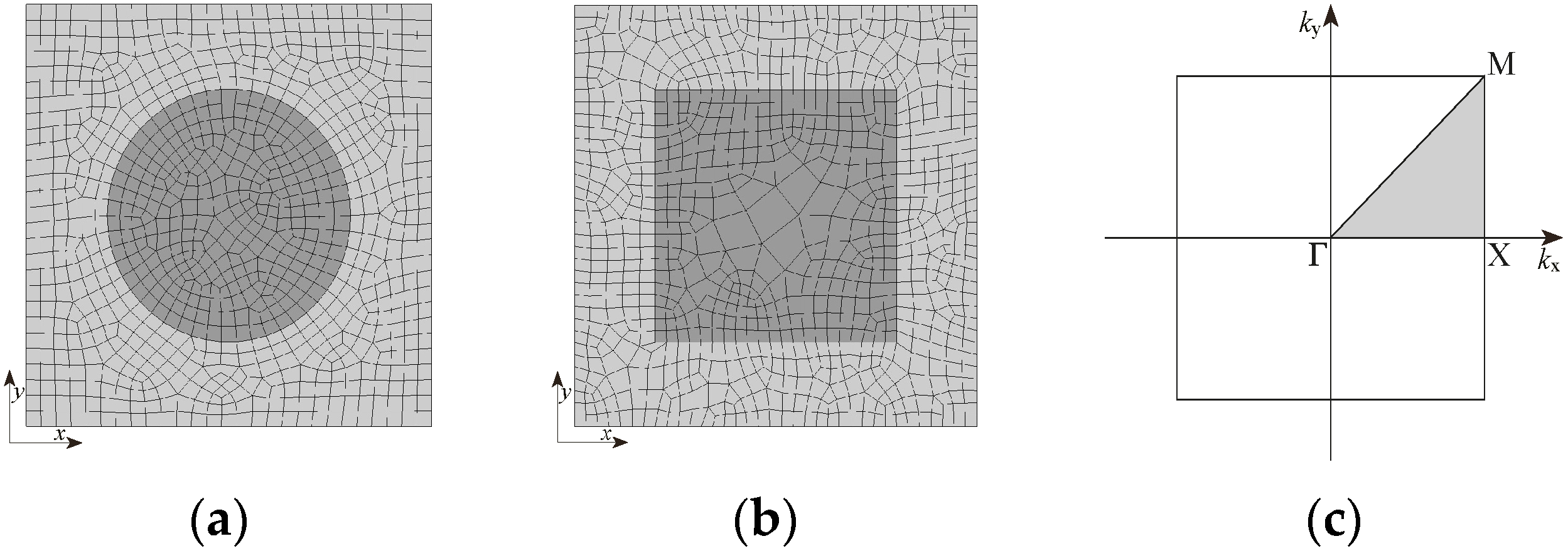
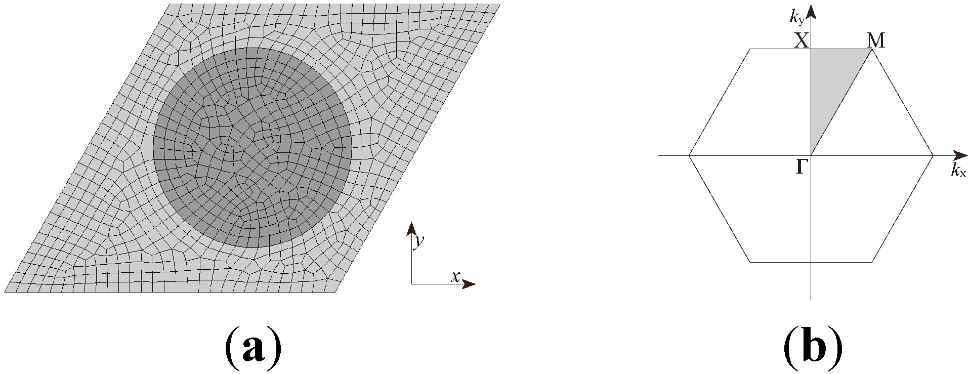
2.1. The Model

2.2. The Conventional FEM
2.3. Application of the Bloch’s Theorem in an Element
2.4. The Boundary Treatment

2.5. The Generalized Eigenvalue Problem
2.6. The Weight Function Treatment
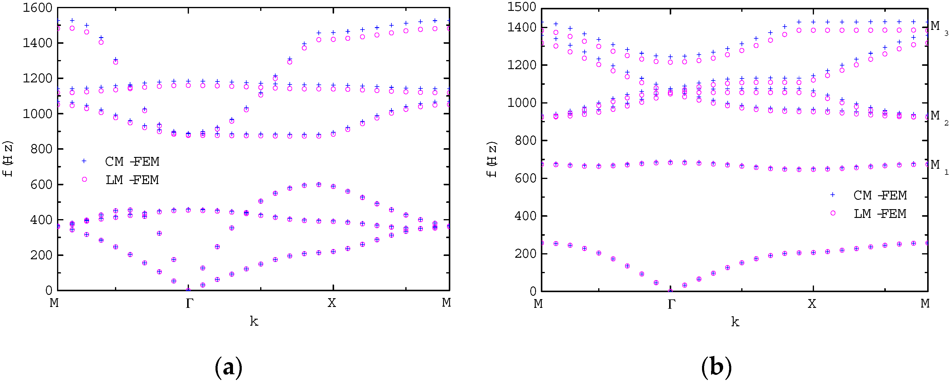
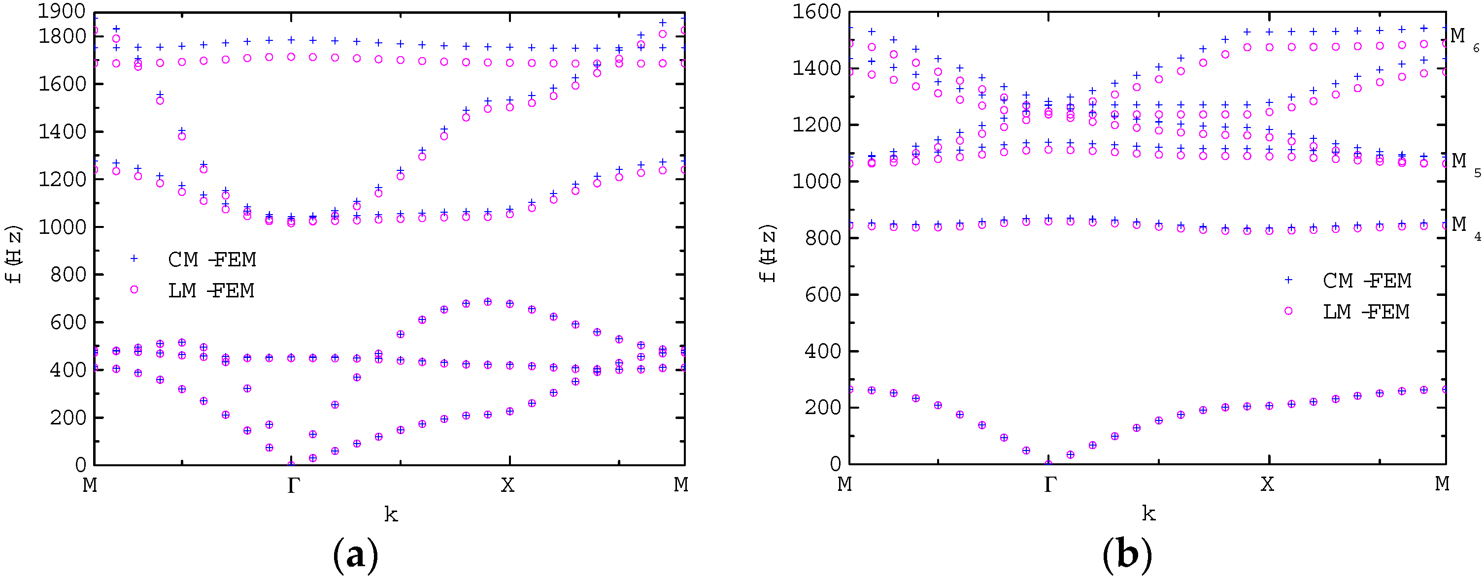
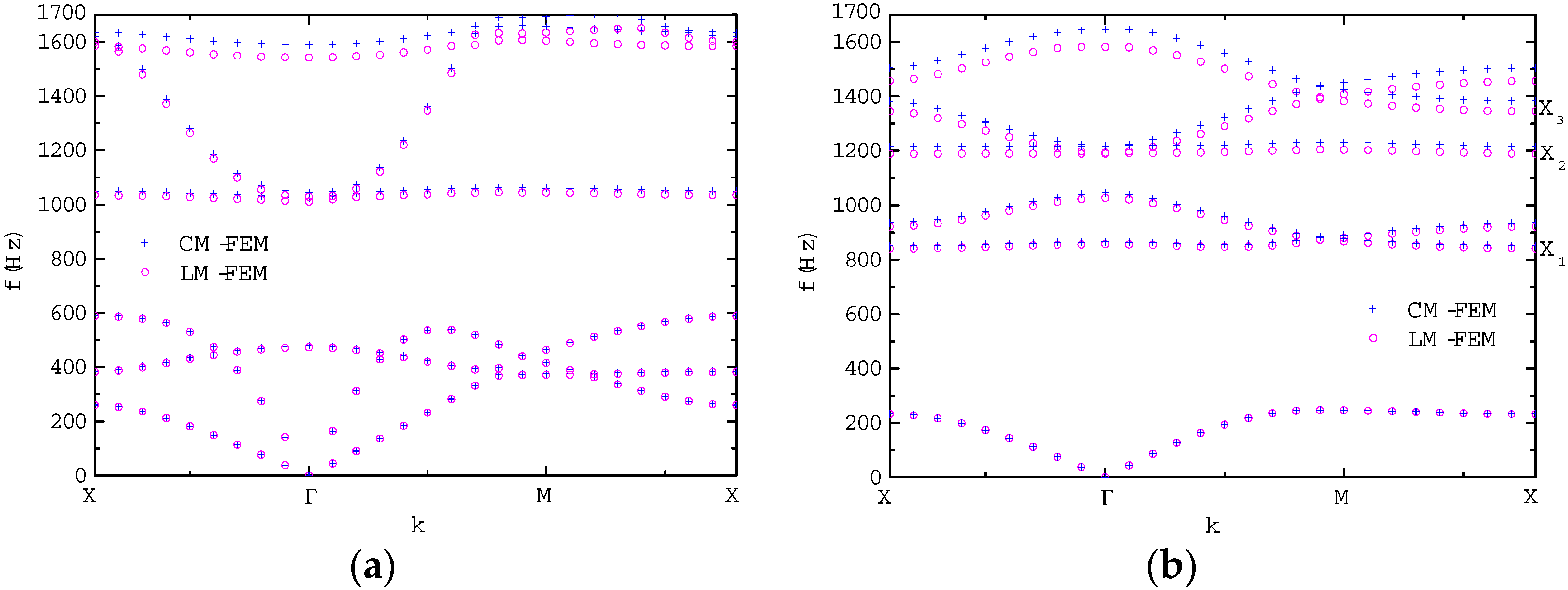
3. Results and Discussion
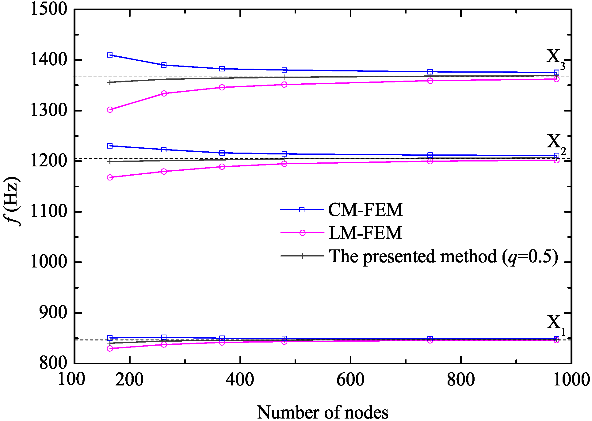
3.1. Determination of the Weight


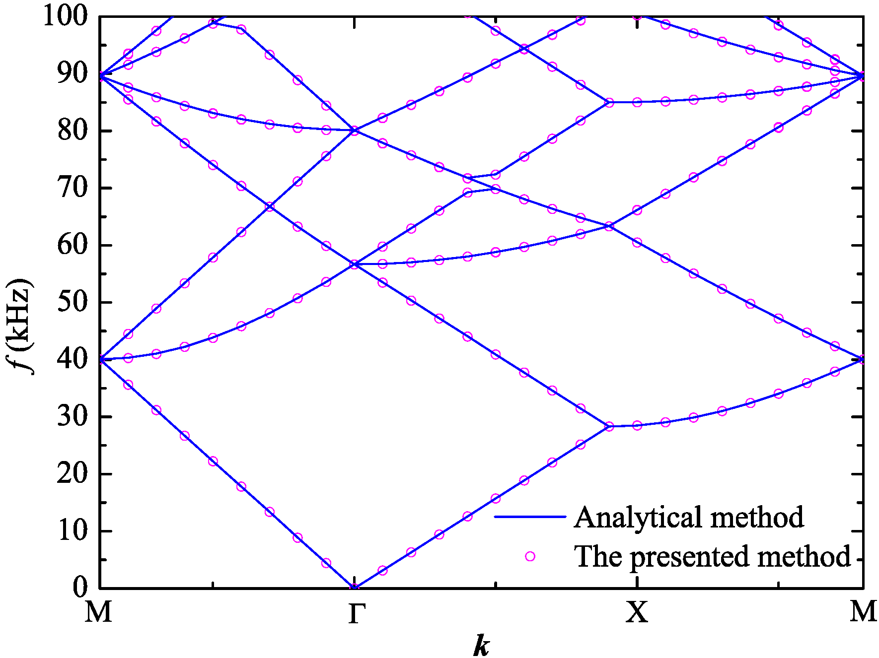
3.2. Analytical Solution of Z Mode Wave Propagation

3.3. Computational Efficiency

| Mode | The Presented Method (393 nodes) | CM-FEM (934 nodes) | LM-FEM (934 nodes) |
|---|---|---|---|
| XY | 504.4 | 4368.0 | 4340.8 |
| Z | 45.7 | 488.9 | 482.0 |
| Mode | The Presented Method (379 nodes) | CM-FEM (936 nodes) | LM-FEM (936 nodes) |
|---|---|---|---|
| XY | 430.0 | 4204.6 | 4168.0 |
| Z | 37.7 | 477.9 | 463.8 |
| Mode | The Presented Method (367 nodes) | CM-FEM (973 nodes) | LM-FEM (973 nodes) |
|---|---|---|---|
| XY | 391.7 | 4966.2 | 4933.8 |
| Z | 34.3 | 545.9 | 546.8 |
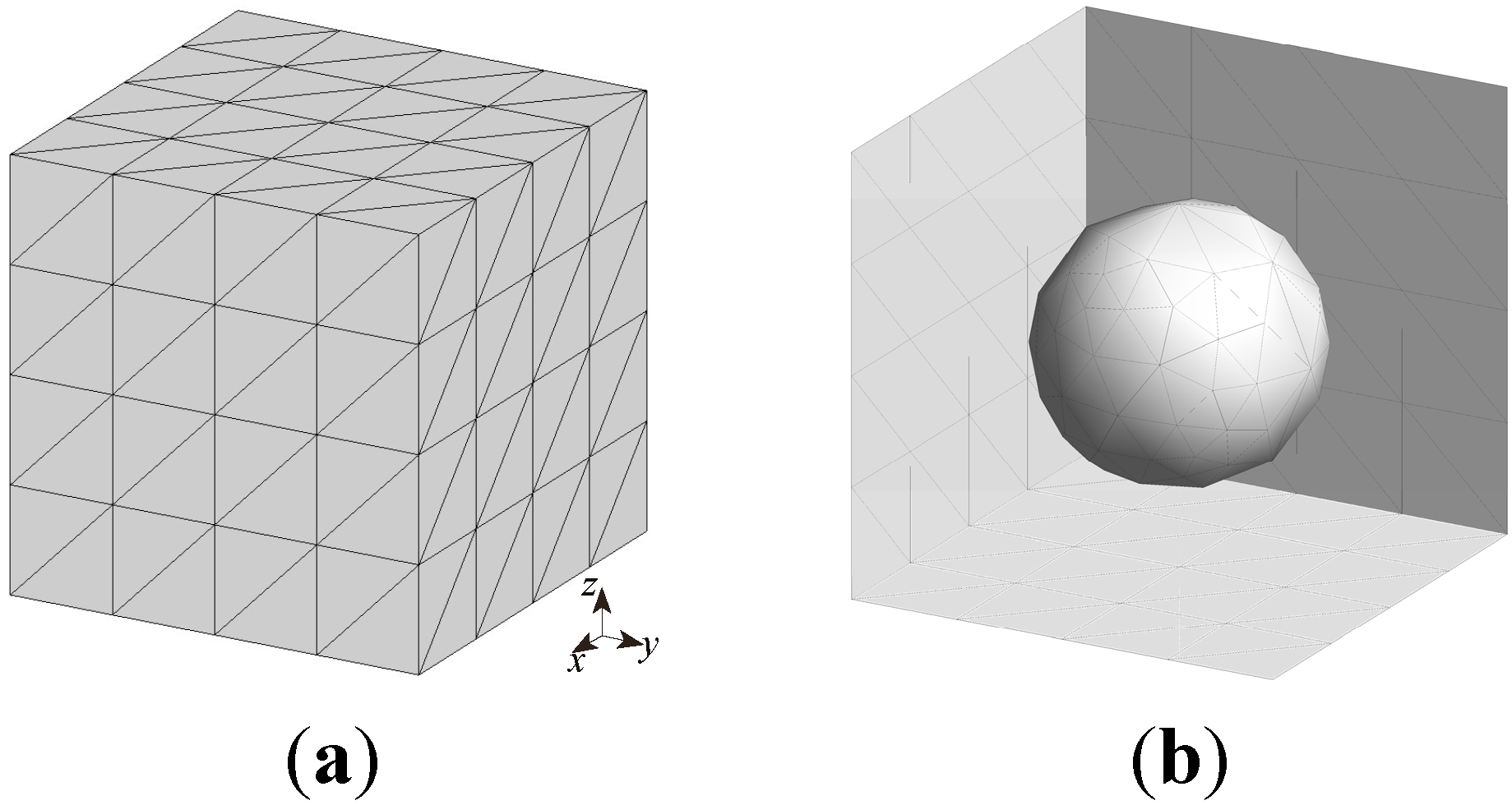
3.4. Extension To Three Dimensional Problem


4. Conclusions
Acknowledgments
Author Contributions
Conflicts of Interest
References
- Sigalas, M.M.; Economou, E.N. Elastic and acoustic wave band structure. J. Sound Vib. 1992, 158, 377–382. [Google Scholar] [CrossRef]
- Kushwaha, M.S.; Halevi, P.; Dobrzynski, L.; Djafari-Rouhani, B. Acoustic band structure of periodic elastic composites. Phys. Rev. Lett. 1993, 71, 2022–2025. [Google Scholar] [CrossRef] [PubMed]
- Martinezsala, R.; Sancho, J.; Sanchez, J.V.; Gomez, V.; Llinares, J.; Meseguer, F. Sound attenuation by sculpture. Nature 1995, 378, 241. [Google Scholar] [CrossRef]
- Liu, Z.; Zhang, X.; Mao, Y.; Zhu, Y.Y.; Yang, Z.; Chan, C.T.; Sheng, P. Locally resonant sonic materials. Science 2000, 289, 1734–1736. [Google Scholar] [CrossRef] [PubMed]
- Wen, J.; Wang, G.; Yu, D.; Zhao, H.; Liu, Y. Theoretical and experimental investigation of flexural wave propagation in straight beams with periodic structures: Application to a vibration isolation structure. J. Appl. Phys. 2005, 97, 114907. [Google Scholar] [CrossRef]
- Graczykowski, B.; Sledzinska, M.; Alzina, F.; Gomis-Bresco, J.; Reparaz, J.S.; Wagner, M.R.; Sotomayor, C.M. Phonon dispersion in hypersonic two-dimensional phononic crystal membranes. Phys. Rev. B 2015, 91, 95414. [Google Scholar] [CrossRef]
- Zen, N.; Puurtinen, T.A.; Isotalo, T.J.; Chaudhuri, S.; Maasilta, I.J. Engineering thermal conductance using a two-dimensional phononic crystal. Nat. Commun. 2014, 5, 3435. [Google Scholar] [CrossRef] [PubMed]
- Gomis-Bresco, J.; Navarro-Urrios, D.; Oudich, M.; El-Jallal, S.; Griol, A.; Puerto, D.; Chavez, E.; Pennec, Y.; Djafari-Rouhani, B.; Alzina, F.; Martínez, A.; Torres, C.M.S. A one-dimensional optomechanical crystal with a complete phononic band gap. Nat. Commun. 2014, 5, 4452. [Google Scholar] [CrossRef] [PubMed]
- Sigalas, M.M.; Soukoulis, C.M. Elastic-wave propagation through disordered and/or absorptive layered systems. Phys. Rev. B 1995, 51, 2780–2789. [Google Scholar] [CrossRef]
- Han, L.; Zhang, Y.; Ni, Z.; Zhang, Z.; Jiang, L. A modified transfer matrix method for the study of the bending vibration band structure in phononic crystal Euler beams. Phys. B 2012, 407, 4579–4583. [Google Scholar] [CrossRef]
- Zhang, Y.; Ni, Z.; Han, L.; Zhang, Z.; Chen, H. Study of improved plane wave expansion method on phononic crystal. Optoelectron. Adv. Mater. 2011, 5, 870–873. [Google Scholar]
- Tanaka, Y.; Tomoyasu, Y.; Tamura, S. Band structure of acoustic waves in phononic lattices: Two-dimensional composites with large acoustic mismatch. Phys. Rev. B 2000, 62, 7387–7392. [Google Scholar] [CrossRef]
- Garcia-Pablos, D.; Sigalas, M.; De Espinosa, F.M.; Torres, M.; Kafesaki, M.; Garcia, N. Theory and experiments on elastic band gaps. Phys. Rev. Lett. 2000, 84, 4349–4352. [Google Scholar] [CrossRef] [PubMed]
- Kafesaki, M.; Economou, E.N. Multiple-scattering theory for three-dimensional periodic acoustic composites. Phys. Rev. B 1999, 60, 11993. [Google Scholar] [CrossRef]
- Liu, Z.; Chan, C.; Sheng, P. Elastic wave scattering by periodic structures of spherical objects: Theory and experiment. Phys. Rev. B 2000, 62, 2446–2457. [Google Scholar] [CrossRef]
- Langlet, P.; Hladky-Hennion, A.; Decarpigny, J. Analysis of the propagation of plane acoustic waves in passive periodic materials using the finite element method. J. Acoust. Soc. Am. 1995, 98, 2792–2800. [Google Scholar] [CrossRef]
- Vasseur, J.O.; Hladky-Hennion, A.; Djafari-Rouhani, B.; Duval, F.; Dubus, B.; Pennec, Y.; Deymier, P.A. Waveguiding in two-dimensional piezoelectric phononic crystal plates. J. Appl. Phys. 2007, 101, 114904. [Google Scholar] [CrossRef]
- Wang, G.; Wen, J.; Liu, Y.; Wen, X. Lumped-mass method for the study of band structure in two-dimensional phononic crystals. Phys. Rev. B 2004, 69, 184302. [Google Scholar] [CrossRef]
- Wang, G.; Wen, J.; Wen, X. Quasi-one-dimensional phononic crystals studied using the improved lumped-mass method: Application to locally resonant beams with flexural wave band gap. Phys. Rev. B 2005, 71, 104302. [Google Scholar] [CrossRef]
- Kim, K. A review of mass matrices for Eigenproblems. Comput. Struct. 1993, 46, 1041–1048. [Google Scholar] [CrossRef]
- Ma, T.C.; Scott, R.A.; Yang, W.H. Harmonic wave propagation in an infinite elastic medium with a periodic array of cylindrical pores. J. Sound Vib. 1980, 71, 473–482. [Google Scholar] [CrossRef]
- Accorsi, M.L.; Bennett, M.S. A finite element based method for the analysis of free wave propagation in stiffened cylinders. J. Sound Vib. 1991, 148, 279–292. [Google Scholar] [CrossRef]
- Ruffa, A.A. Acoustic wave propagation through periodic bubbly liquids. J. Acoust. Soc. Am. 1992, 91, 1–11. [Google Scholar] [CrossRef]
- Sigmund, O.; Jensen, J.S. Systematic design of phononic band-gap materials and structures by topology optimization. Phil. Trans. Roy. Soc. Lond. A 2003, 361, 1001–1019. [Google Scholar] [CrossRef] [PubMed]
- Liu, Y.; Gao, L. Explicit dynamic finite element method for band-structure calculations of 2D phononic crystals. Solid State Commun. 2007, 144, 89–93. [Google Scholar] [CrossRef]
- Mace, B.R.; Manconi, E. Modelling wave propagation in two-dimensional structures using finite element analysis. J. Sound Vib. 2008, 318, 884–902. [Google Scholar] [CrossRef]
- Hennion, A.C.; Bossut, R.; Decarpigny, J.N.; Audoly, C. Analysis of the scattering of a plane acoustic wave by a periodic elastic structure using the finite element method: Application to compliant tube gratings. J. Acoust. Soc. Am. 1990, 87, 1861–1870. [Google Scholar] [CrossRef]
- Hladky-Hennion, A.; Decarpigny, J. Analysis of the scattering of a plane acoustic wave by a doubly periodic structure using the finite element method: Application to Alberich anechoic coatings. J. Acoust. Soc. Am. 1991, 90, 3356–3367. [Google Scholar] [CrossRef]
- Hladky-Hennion, A.; Decarpigny, J.E.L. Finite element modeling of active periodic structures: Application to 1–3 piezocomposites. J. Acoust. Soc. Am. 1993, 94, 621–635. [Google Scholar] [CrossRef]
- Li, J.; Wang, Y.S.; Zhang, C. Finite element method for analysis of band structures of three dimensonal phononic crystals. In Proceedings of the 2008 IEEE International Ultrasonics Symposium Proceedings, Beijing, China, 2–5 November 2008.
- Wu, L.Y.; Chen, L.W.; Wang, R.C.C. Dispersion characteristics of negative refraction sonic crystals. Phys. B 2008, 403, 3599–3603. [Google Scholar] [CrossRef]
- Wu, L.; Chen, L. Acoustic band gaps of the woodpile sonic crystal with the simple cubic lattice. J. Phys. D Appl. Phys. 2011, 44, 45402. [Google Scholar] [CrossRef]
- Eringen, A.C.; Suhubi, E.S. Elastodynamics, Volume II: Linear Theory; Academic Press: New York, NY, USA, 1975. [Google Scholar]
- Zienkiewicz, O.C.; Taylor, R.L. The Finite Element Method, Volume I: The Basis, 5th ed.; Butterworth-Heinemann: Oxford, UK, 2000. [Google Scholar]
- Kittel, C.; McEuen, P. Introduction to Solid State Physics; Wiley: New York, NY, USA, 1996. [Google Scholar]
- Clough, R.W.; Penzien, J. Dynamics of Structures; McGraw-Hill: New York, NY, USA, 1993. [Google Scholar]
- Wilkinson, J.H. The Algebraic Eigenvalue Problem; Clarendon Press: Oxford, UK, 1965. [Google Scholar]
- Wen, X.; Wen, J.; Yu, D.; Wang, G.; Liu, Y.; Han, X. Phononic Crystals; National Defence Industry Press: Beijing, China, 2009. [Google Scholar]
- Still, T.; Oudich, M.; Auerhammer, G.K.; Vlassopoulos, D.; Djafari-Rouhani, B.; Fytas, G.; Sheng, P. Soft silicone rubber in phononic structures: Correct elastic moduli. Phys. Rev. B 2013, 88, 94102. [Google Scholar] [CrossRef]
- Tong, P.; Pian, T.; Bucciarblli, L.L. Mode shapes and frequencies by finite element method using consistent and lumped masses. Comput. Struct. 1971, 1, 623–638. [Google Scholar] [CrossRef]
- Alonso-Redondo, E.; Schmitt, M.; Urbach, Z.; Hui, C.M.; Sainidou, R.; Rembert, P.; Matyjaszewski, K.; Bockstaller, M.R.; Fytas, G. A new class of tunable hypersonic phononic crystals based on polymer-tethered colloids. Nat. Commun. 2015, 6, 8309. [Google Scholar] [CrossRef] [PubMed]
- AFEM Code. Available online: http://www.researchgate.net/publication/283538731_AFEM_code (accessed on 13 January 2016).
© 2016 by the authors; licensee MDPI, Basel, Switzerland. This article is an open access article distributed under the terms and conditions of the Creative Commons by Attribution (CC-BY) license (http://creativecommons.org/licenses/by/4.0/).
Share and Cite
Han, L.; Zhang, Y.; Li, X.-m.; Jiang, L.-h.; Chen, D. Accelerated Approach for the Band Structures Calculation of Phononic Crystals by Finite Element Method. Crystals 2016, 6, 11. https://doi.org/10.3390/cryst6010011
Han L, Zhang Y, Li X-m, Jiang L-h, Chen D. Accelerated Approach for the Band Structures Calculation of Phononic Crystals by Finite Element Method. Crystals. 2016; 6(1):11. https://doi.org/10.3390/cryst6010011
Chicago/Turabian StyleHan, Lin, Yan Zhang, Xiao-mei Li, Lin-hua Jiang, and Da Chen. 2016. "Accelerated Approach for the Band Structures Calculation of Phononic Crystals by Finite Element Method" Crystals 6, no. 1: 11. https://doi.org/10.3390/cryst6010011