Article

The Mechanical Properties and Corrosion Resistance of Magnesium Alloys with Different Alloying Elements for Bone Repair

1
School of Materials Science and Engineering, Tianjin University of Technology, Tianjin 300384, China
2
Key Laboratory of Display Materials and Photoelectric Device (Ministry of Education), Tianjin 300384, China
3
Tianjin Key Lab for Photoelectric Materials & Devices, Tianjin 300384, China
4
School of Materials Science and Engineering, Northeastern University, Shenyang 110819, China
*
Author to whom correspondence should be addressed.
Crystals 2018, 8(7), 271; https://doi.org/10.3390/cryst8070271
Submission received: 20 May 2018 / Revised: 23 June 2018 / Accepted: 24 June 2018 / Published: 28 June 2018

Abstract

:
In order to make a rational design of magnesium alloys for bone repair, four kinds of Mg alloy ingots were prepared by vacuum induction furnace, namely Mg-3Zn-0.2Ca (wt.%) (ZX30), Mg-3Zn-0.8Zr (wt.%) (ZK30), Mg-3Zn-0.8Zr-0.3Sr (wt.%) (ZKJ300) and Mg-3Zn-0.8Zr-0.3Ca-0.3Ag (wt.%) (ZKXQ3000) alloys. The four ingots were extruded into bar materials through a hot-extrusion process under different temperatures with different extrusion ratios, the mechanical performances and the corrosion behaviors in the simulated body fluid (SBF) of the four alloys were investigated, and the mechanism of fracture and corrosion was characterized by scanning electron microscopy (SEM). The results showed the ultimate compressive strength (UCS) of all the alloys were found to be around 360 MPa, while ultimate tensile strengths (UTS) of ZKJ300 (334.61 ± 2.92 MPa) and ZKXQ3000 (337.56 ± 2.19 MPa) alloys were much higher than those of ZX30 (298.17 ± 0.93 MPa) and ZK30 (293.26 ± 2.71 MPa) alloys. The electrochemical noise and immersion tests in the SBF indicated that ZK30 alloy performed better in corrosion resistance.

Graphical Abstract

1. Introduction

Magnesium (Mg) alloy has become a typical and new representative material of degradable implants, because of its comprehensive mechanical properties matched with natural bone and excellent biodegradation characteristics [1,2], and it has a great marketing prospect and is widely used in degradable medical devices. However, its fast degradation rate, causing the great reduction of the mechanical properties and stability of implant materials, and resulting in the failure of materials [3,4], has restricted its clinical application in fracture fixation. Meanwhile, a large number of bubbles produced by degradation can significantly affect the physiological functions of the surrounding tissues and the restoration of the implanted sites [5,6]. Moreover, the fast degradation rate leads to the increment of pH value of the body fluid near the implants, which is potentially harmful to human bone and tissue growth [7]. Therefore, it is very important to control the degradation properties of magnesium alloys to ensure their mechanical integrity and match the tissue growth rate.
There have been many methods for improving the properties of magnesium alloys, including high purification of magnesium and its alloys, alloying, improvement of the preparation process, deformation processing, heat treatment and so forth. Alloying is one of the simplest and effective methods used for enhancing the properties of magnesium alloys [2,8]. There are various alloying elements that can be selected, including Ca, Sr, Zn, Mn, Zr, Nd, Li, Al, etc. [9,10,11,12]. However, the related reports have revealed that there are some risks in the implantation of Mn, Nd, Li, Al and etc. through animal experiments [13,14,15]. Since the alloy is designed to be implanted in the human body, like bone screw, the biological safety is greatly important for designing consideration, which means to select bio-functional elements with non-toxicity and degradation. In previous works, researchers [16,17,18,19,20] found that the addition of some biological functional elements such as Ca, Sr, Zn and Ag could benefit by not only refining alloy grain size, but also playing the role of solid solution strengthening, age hardening and sterilization. Du et al. [21] reported that the addition of the alloying element Ca inhibited dynamic recrystallization and grain growth and promoted dynamic precipitation during the extrusion process, which raised the yield strength of Mg-6Zn from 125 MPa to 230 MPa. Cheng et al. [19] found that Sr could effectively refine grain and produce more intermetallic compounds, and Mg-5Zn alloy with 0.2%Sr content comprehensively performed very well. Huang et al. [22,23,24] studied the effect of Ag, Zn and Ca on the microstructure and aging behavior of Mg-Sn alloys from different aspects and found that the addition of alloying elements could greatly increase the hardness of the Mg-Sn alloy and enhance the age hardening effect. Also, some previous studies [25] showed that the elements such as Ca and Sr not only had high biological safety, but also were the main components of human bone, and are significantly favorable to induce osteogenesis. In addition, there were no adverse reactions after implantation of pure magnesium and Mg-5Ca-1Zn, which obtained satisfactory therapeutic effects [26,27,28].
In this present work, Ca, Zr, Sr and Ag elements were added to the Mg-3Zn alloy to enhance its comprehensive properties on the basis of previous work [29,30,31], and the effects of these elements on the microstructure, mechanical properties and corrosion behavior of Mg-3Zn alloys were further investigated. The purpose of this study is to select an internal fracture fixation material with high biological safety and reliable performance and provide more experimental evidence for the development of new medical devices.

2. Materials and Methods

2.1. Materials and Specimen Preparation

Pure magnesium (99.99 wt.%) ingot, pure zinc (99.99 wt.%) particles, Mg-Ca master alloy (with 25.20 wt.% Ca), Mg-Zr master alloy (with 30.80 wt.% Zr), Mg-Sr master alloy (with 25.11 wt.% Sr) and Mg-Ag master alloy (with 10.33 wt.% Ag) were used to prepare Mg-3Zn-0.2Ca (wt.%) (ZX30), Mg-3Zn-0.8Zr (wt.%) (ZK30), Mg-3Zn-0.8Zr-0.3Sr (wt.%) (ZKJ300) and Mg-3Zn-0.8Zr-0.3Ca-0.3Ag (wt.%) (ZKXQ3000) alloys. The whole procedure, including melting and casting, was carried out at 720 °C in a vacuum induction furnace under the protection of argon gas. These four ingots, subjected to different homogenizing annealing, were extruded into bar materials through a hot-extrusion process under different temperatures with different extrusion ratio afterwards.

2.2. Microstructure

Microstructures of the Mg alloys were observed by scanning electron microscopy (SEM) (FE-SEM, 6700F, JEOL, Japan) after as-extruded disk specimens mechanically grinded down to 0.05 μm, then chemically polished and corroded. Phase compositions were detected by X-ray diffraction (XRD, D/max/2500PC, Rigaku, Japan) using CuKα radiation (λ = 0.15418 nm) at a scanning speed of 10°/min with 40 Kv of the acceleration voltage and 100 mA of the current. Jade5 software was used to analyze data after testing.

2.3. Mechanical Property Tests

Experimental specimens were machined according to GB/T 16865-2013, GB/T 7314-2005, respectively, with the surface of samples subsequently polished down to a surface finish of 0.05 μm. Following the corresponding operation process, mechanical tests were conducted at a displacement rate of 0.5 mm/min under ambient temperature on a universal material testing machine (Instron 5969) after a stress relief annealing at 170 °C for 1 hour (h). Fracture morphology of failed specimens was examined and analyzed by SEM. An average of three measurements was taken for each group.

2.4. Electrochemical Noise Tests

Electrochemical noise tests were carried out using electrochemical noise module of GillAC electrochemical workstation with two identical samples as working electrodes and a saturated calomel electrode as a reference electrode to measure the galvanic current and electrode potential between the two same working electrodes. Each group of electrochemical noise records contained 4096 data points, the time interval was 0.5 seconds (s), and the measurement time was 2048 s. Samples were tested after immersing for 0, 2 h, 1 day (d), 3 d, 5 d, 7 d, 10 d, 15 d in SBF. The surface of the sample was mechanically grinded down to 0.05 μm before testing. All the electrochemical experiments were carried out at room temperature and repeated thrice to ensure better reproducibility. The corroded surfaces were observed by SEM. Elemental mappings from the corroded surfaces were acquired by energy dispersive X-ray spectrometry (EDS).

2.5. Immersion Tests

The sample of 3 mm × Φ 8 mm polished down to 0.05 μm was put into the nut bottle and the ratio of SBF solution volume to specimen surface area was 35.5 mL/cm2. The immersion test was carried out in constant temperature water bath oscillator at 37 ± 0.5 °C for 15 d. The pH value of the solution measured by the pH meter (STARTER 3100, OHOUS, America) was detected every 2 h for the first 48 h and the SBF solution was changed every 2 d. The average corrosion rate (mm/year) can be calculated by the following equation (1) in accordance with ASTM-G31-72, in which W is the mass loss (g), K is a constant (8.76 × 10⁴), A is the surface area (cm2), T is the time of immersion (h), and D is the material density (g/cm3). In the experiment, there were three parallel specimens, and the final result was the average of the three sets of experiments.
Corrosion Rate (CR) = (K × W)/(A × T × D),
After immersing for 1 d, 3 d, 5 d, 7 d, 10 d and 15 d in SBF, Corrosion products of the specimens were cleaned using the chromic acid solution and washed in absolute ethanol using an ultrasonic bath at room temperature. Macromorphology images of four kinds of extrusion alloys removing corrosion products were observed by using laser confocal microscope (LCM, OLS 4000, Olympus, Japan).

3. Results

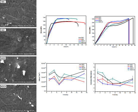
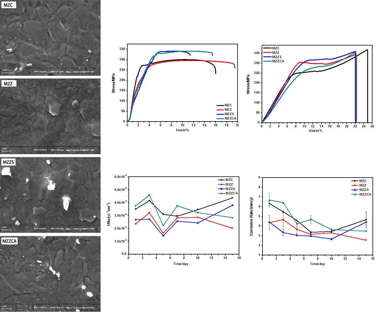
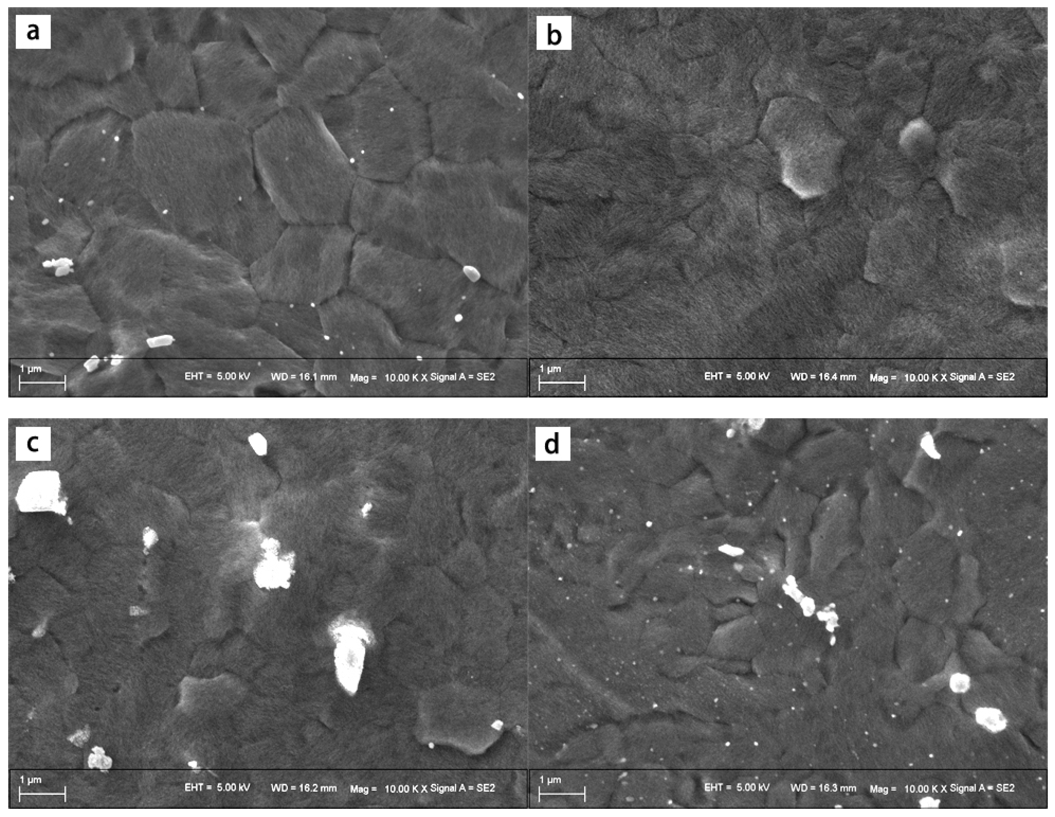
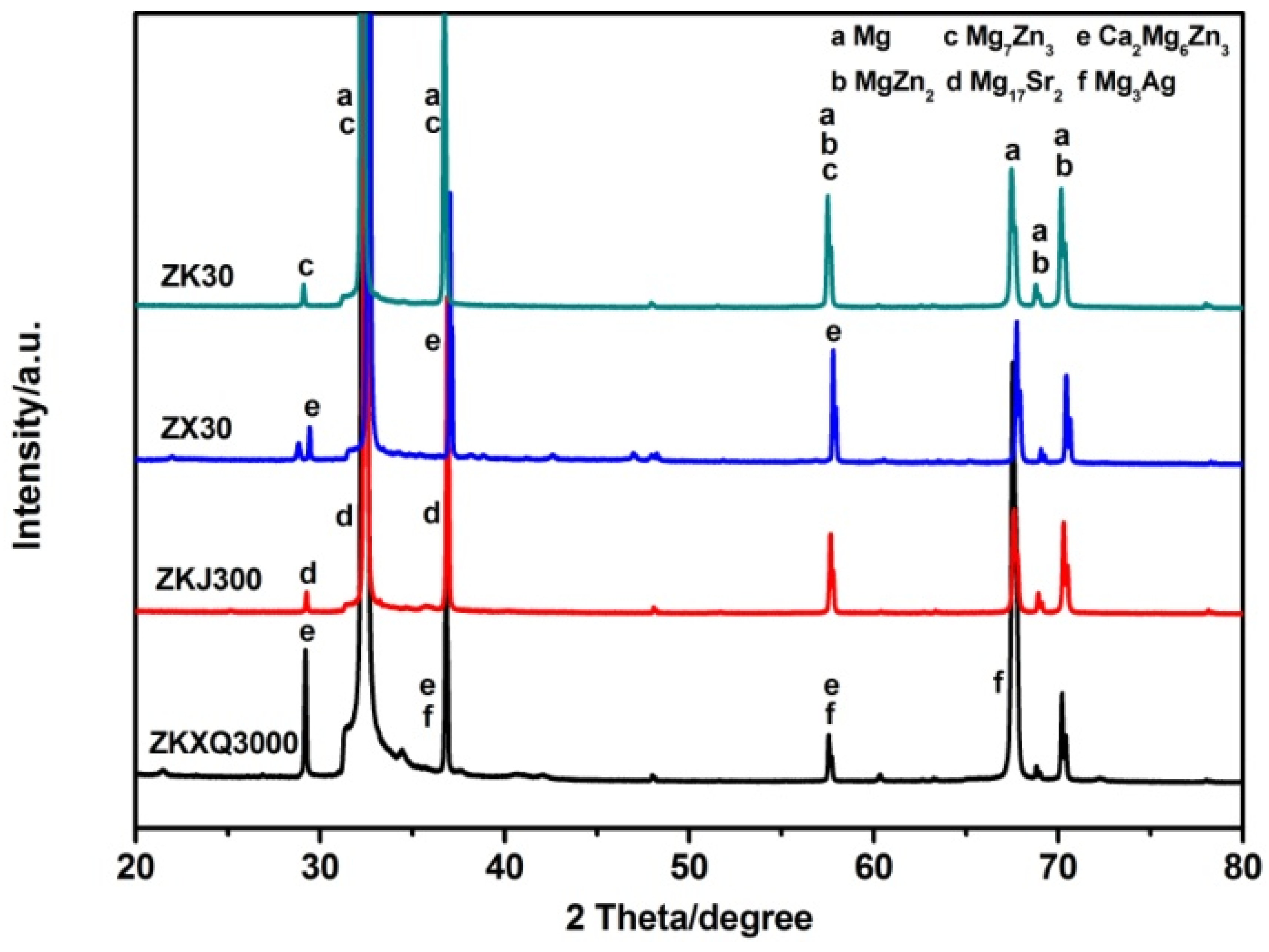
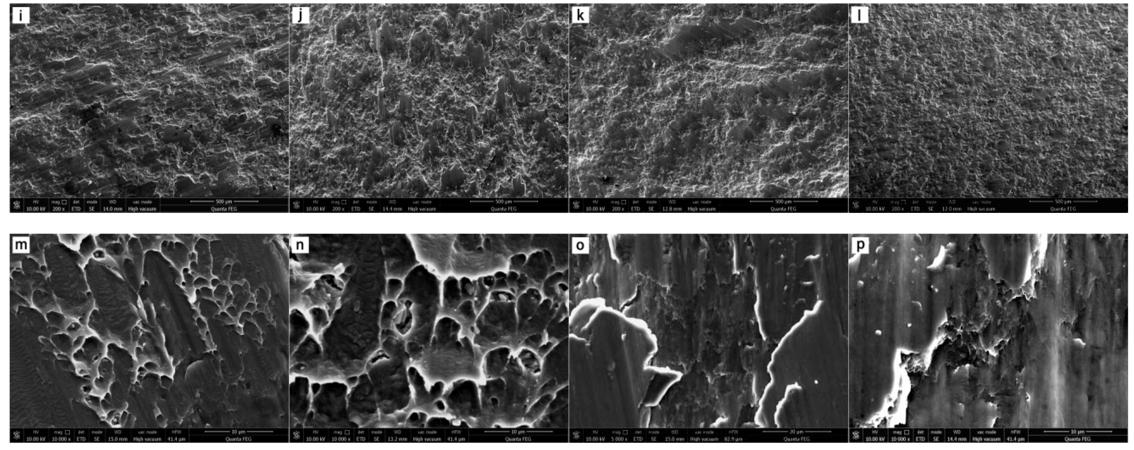
3.1. Microstructural Characterization

Figure 1 shows metallographs of as-extruded ZX30, ZK30, ZKJ300, ZKXQ3000 alloys. As can be seen from Figure 1, the average grain sizes of the ZX30, ZK30, ZKJ300, ZKXQ3000 alloys were 3.2 ± 0.5 μm, 2.5 ± 0.3 μm, 2 ± 0.2 μm, 1.5 ± 0.3 μm, respectively. Furthermore, second phases of ZKXQ3000 were finer and more homogeneously distributed, compared with ZX30 and ZKJ300, but only a few second phases could be observed in the ZK30. The XRD patterns were shown in Figure 2, the alloys consisted of Mg, MgZn2 and Mg7Zn3 phases. Moreover, Ca2Mg6Zn3 and Mg17Sr2 were also found in ZX30, ZKJ300 correspondingly, besides Ca2Mg6Zn3, Mg3Ag could be observed in ZKXQ3000.

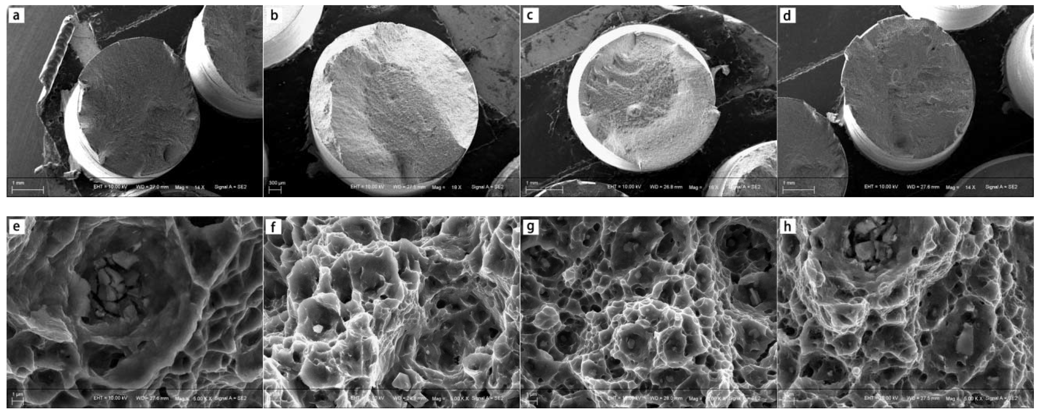
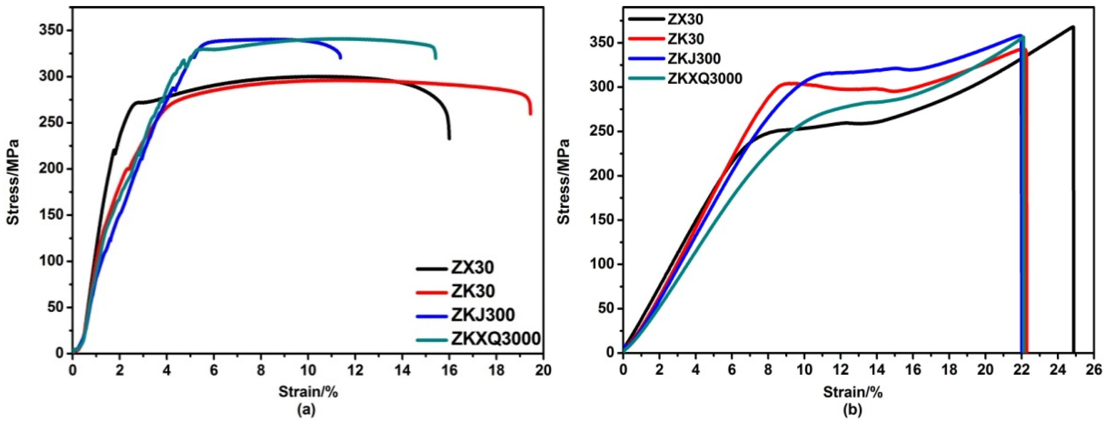
3.2. Mechanical Property Analysis

Figure 3 displays the mechanical properties of the four as-extruded alloys. The yield tensile strength (YTS) of ZKJ300 and ZKXQ3000 was around 20% higher than that of ZX30 and ZK30, but the elongation apparently decreased by 26% (Figure 3a). Although the ultimate compressive strength (UCS) of the four alloys was basically around 360 MPa, the respective yield compression strength (YCS) was obviously different (Figure 3b). Only ZKJ300 could reach more than 310 MPa and other alloys were under 300 MPa. The mechanical data of magnesium alloys are shown in Table 1.
To further explore the mechanical properties of the Mg alloys, it can be studied by observing alloy fracture, as shown in Figure 4. The tensile fracture SEM images of ZX30, ZK30, ZKJ300 and ZKXQ3000 alloys are shown in Figure 4a–d. The cross section was 45 degrees with the maximum normal stress direction, consistent with the maximum shear stress, which corresponded to shear slip fracture. Figure 4e–h represents a large number of dimples with different shapes, sizes and depths in the enlarged tensile fracture, with the second phase particles found in the dimple. Hence, the fracture type of the alloys corresponded to microporous aggregation. Figure 4i–l shows compressive fracture SEM images of four alloys. There was a fluvial pattern extending in cleavage at the fracture, which corresponded to brittle fracture in the form of fracture. The enlarged fracture images, shown in Figure 4m–p, could detect microporous coalescence dimples, which corresponded to the plastic fracture feature, and the fracture mode between the brittle fracture and the plastic fracture was quasi cleavage fracture.

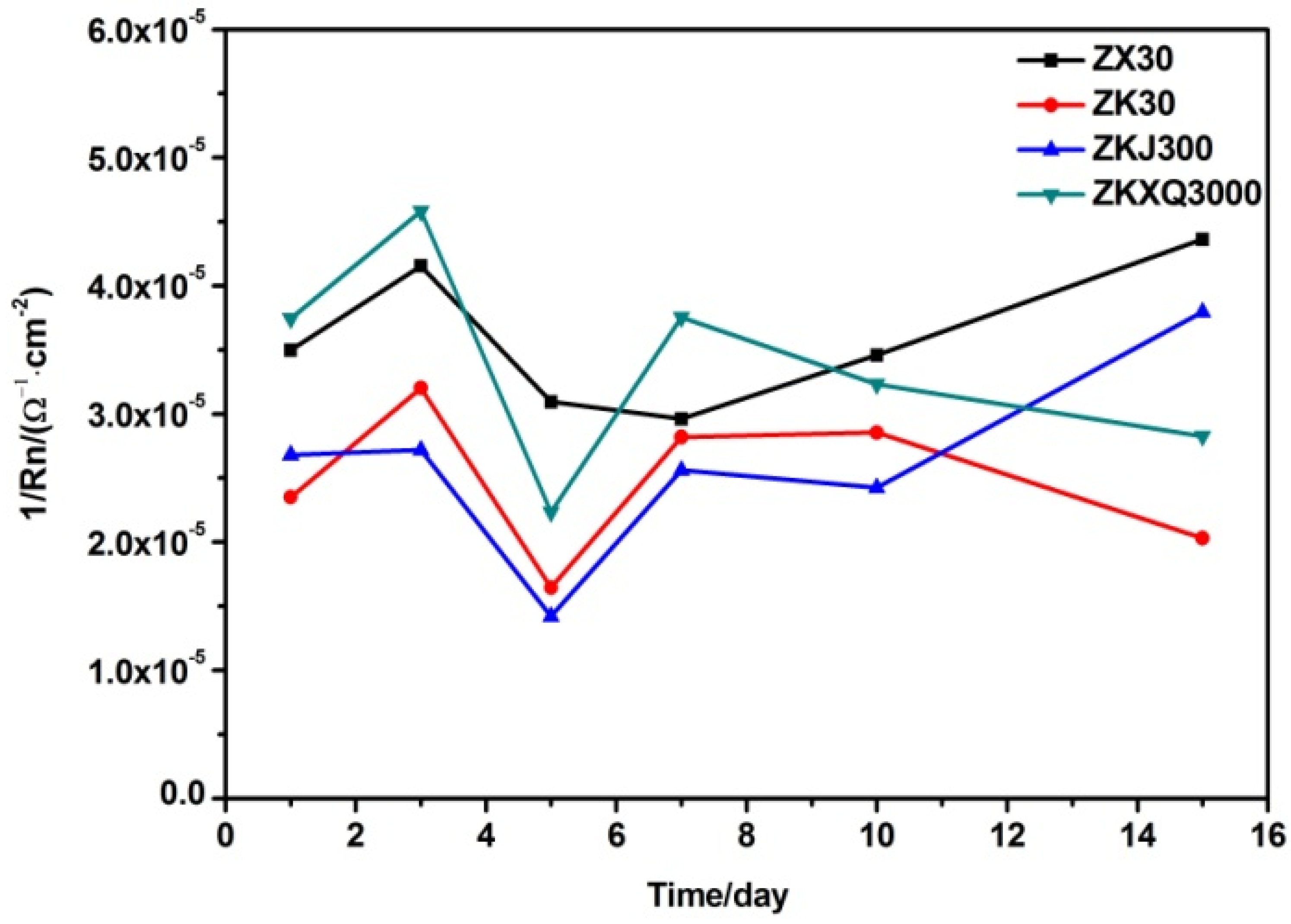
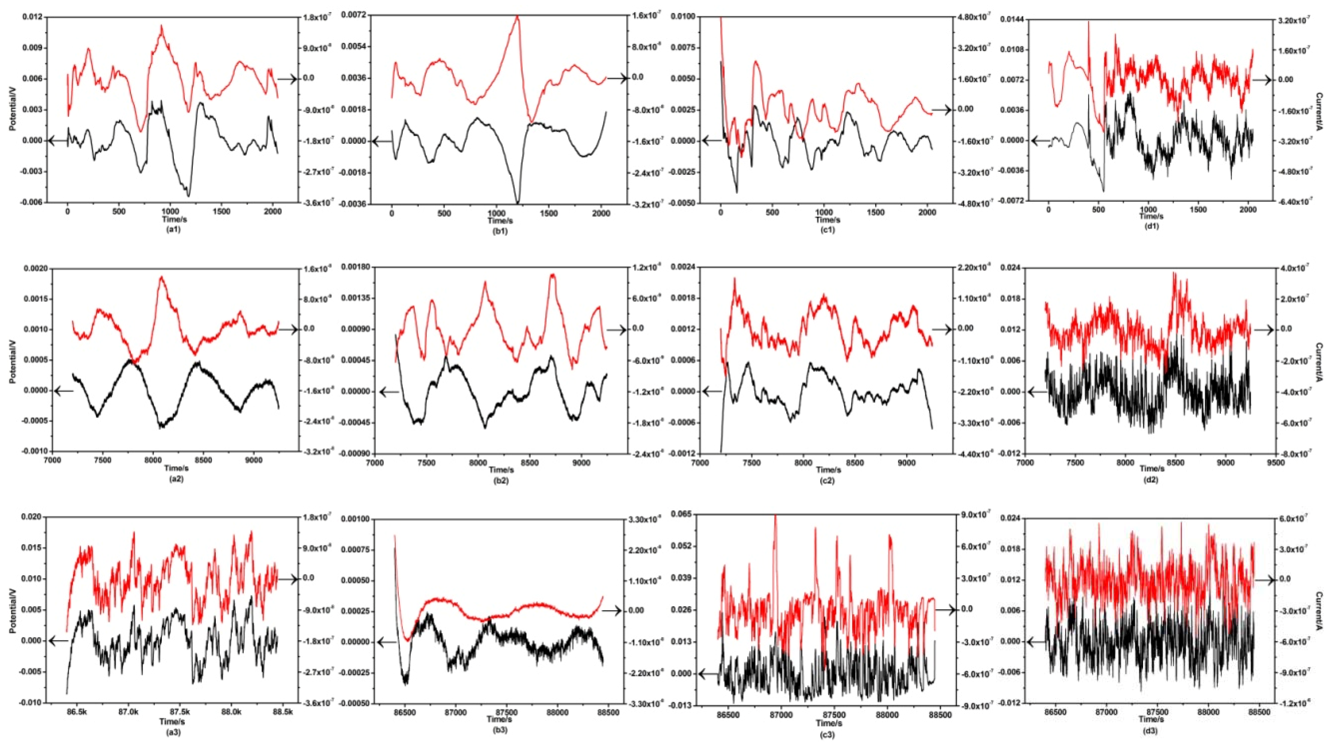
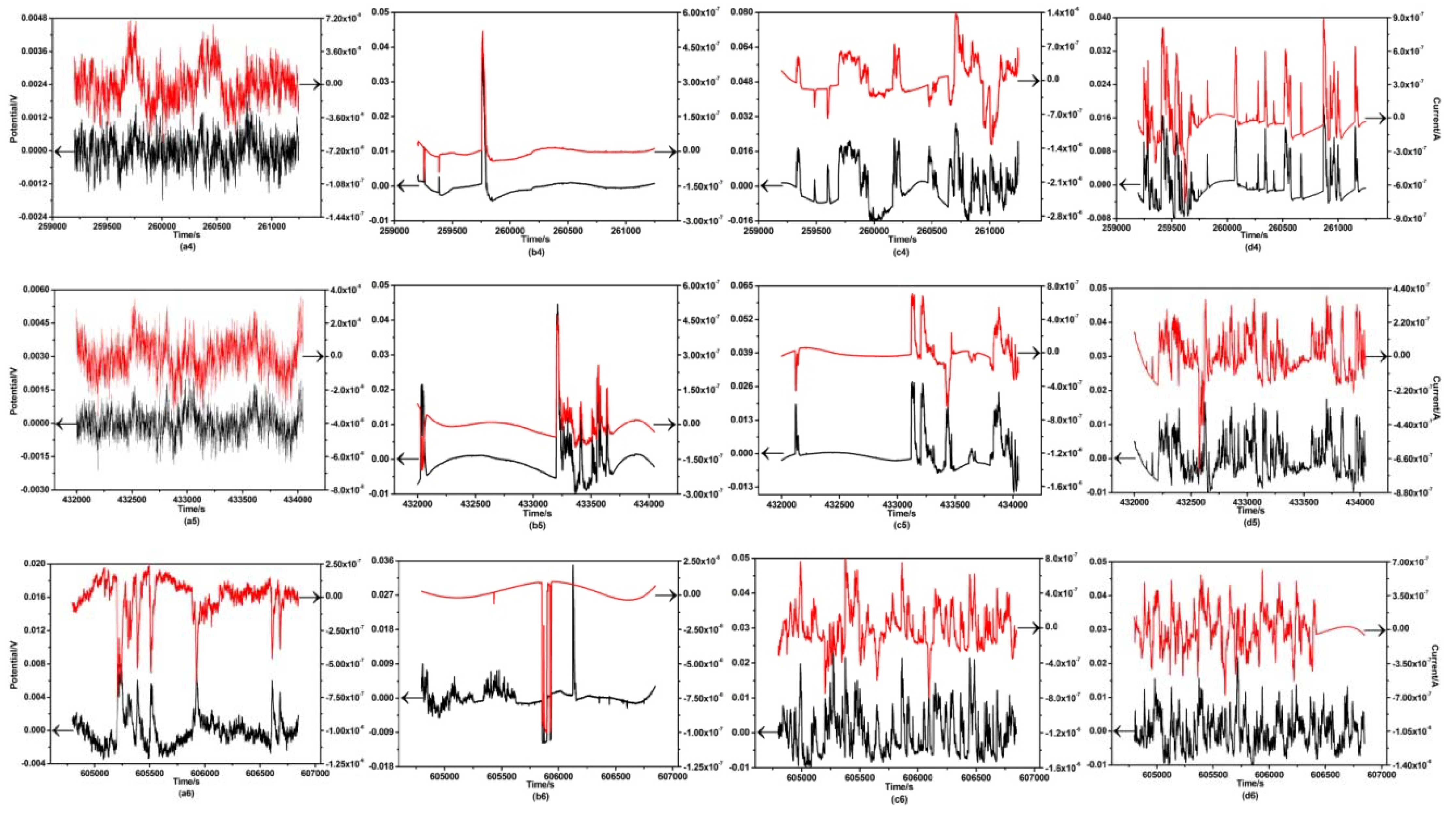
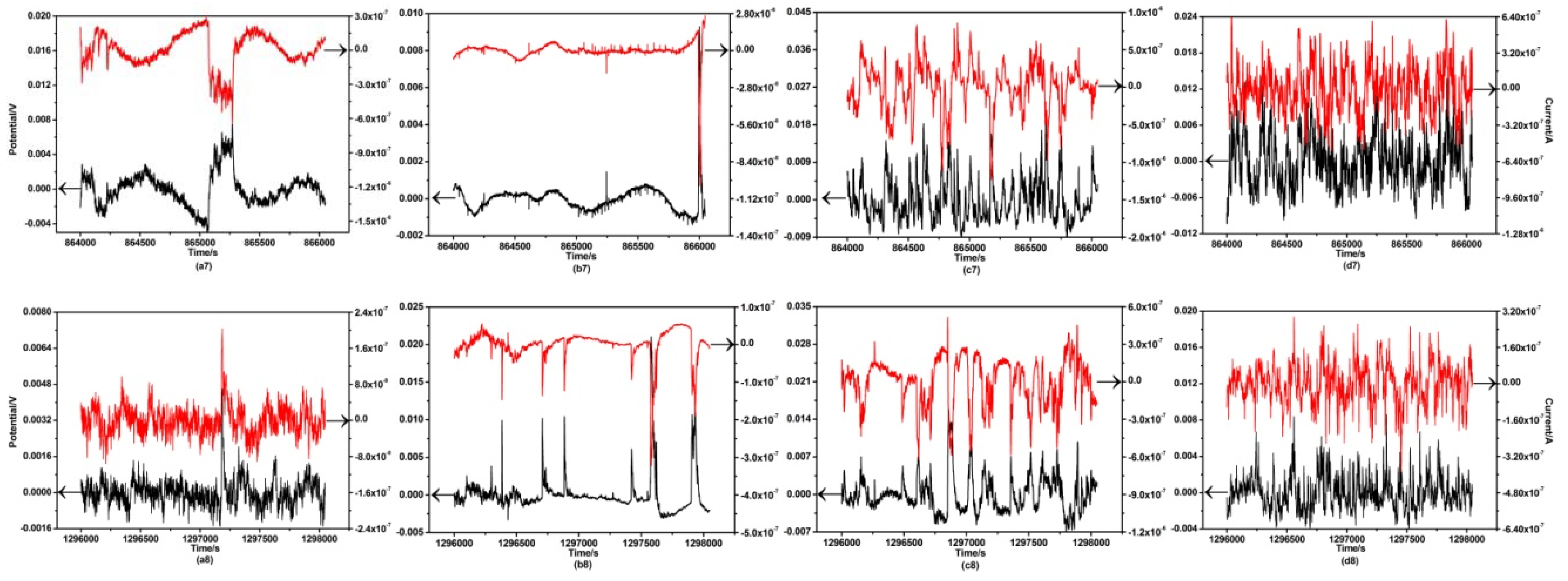
3.3. Electrochemical Noise Analysis

General appearance current and potential time records for all the extruded magnesium alloys immersed in SBF for different days are shown in Figure 5. As shown in Figure 5(a1,b1,c1,d1), the magnesium alloys were directly immersed into the simulated body fluids for electrochemical noise tests. The main trend was that the potential and current noises were in the same direction, which showed that the corrosion of the magnesium alloys was dominated by anodic dissolution process. After 2 h of immersion, the potential noise of ZX30 and ZK30 alloys in the transient mode decreased, with the increase of current noise, indicating that pitting corrosion occurred on the surface.
The current transient of ZK30 alloy immersing for 1 d was stabilized at about 0, illustrating that the surface of the ZK30 alloy was passivated to form a protective film against the erosion of the solution, and the local corrosion was difficult to occur. However, the other three alloys had a large number of periodic high frequency transient waves, indicating a competition between the metastable pitting and the repassivation on the magnesium alloys. At the same time, the difference of periodic interval was due to the different speed of anodic dissolution, and the slower the change was the slower the dissolution rate. It can be seen from Figure 5(a3,b3,c3,d3) that ZKXQ3000 reaction was more intense. With the increase of immersing time, the corrosion layer on the surface of the specimen was exfoliated, and the exposed metal part reacted with the solution, which further made the pitting more serious and gradually formed the corrosion cracks and corrosion craters. The current transient of ZK30 was the most stable after 15 days of immersion. Meanwhile, ZK30 alloy represents the optimal corrosion resistance in the polarization curve and alternating current (AC) impedance spectra shown in Figure S1.
SEM and EDS images of four alloys immersing for 1 d, 5 d and 15 d are shown in Figure 7. At the early stage of immersion, the surface of ZX30 and ZKXQ3000 was distributed with relatively loose flake products, and then the corrosion products changed into larger granules. It could be deduced to be Mg(OH)2 and calcium phosphate compounds from the energy spectra, respectively. In addition, it can be clearly seen that the corrosion pits of ZX30 and ZKXQ3000 were deeper and bigger, compared with ZK30 and ZKJ300 alloys. The surface of ZKJ300 at the beginning and middle stages of immersion displayed small and dense granular products, which were identified as calcium and phosphorus compounds by EDS. However, the corrosion cavities of ZKJ300 alloys became obvious after five days of immersion (Figure 7g). Compared with ZK30 and ZKXQ3000 alloys, ZX30 and ZKJ300 showed relatively loose calcium and phosphorus particles and more serious corrosion cavities in the latter stage of immersion. During the whole immersing process, the surface of ZK30 showed compact granular products, which effectively blocked the infiltration of SBF and played a very good protective role.
In addition, the noise resistance (Rn) is defined as the ratio of a standard deviation of the potential noise to that of current noise in the time domain, which can be associated with the polarization resistance (Rp). The ratio 1/Rn is proportional to the corrosion rate. As shown in Figure 6, the corrosion rate of all the magnesium alloys was immersed for 15 d and could be ranked in the ascending sort order: ZK30 < ZKXQ3000 < ZKJ300 < ZX30.

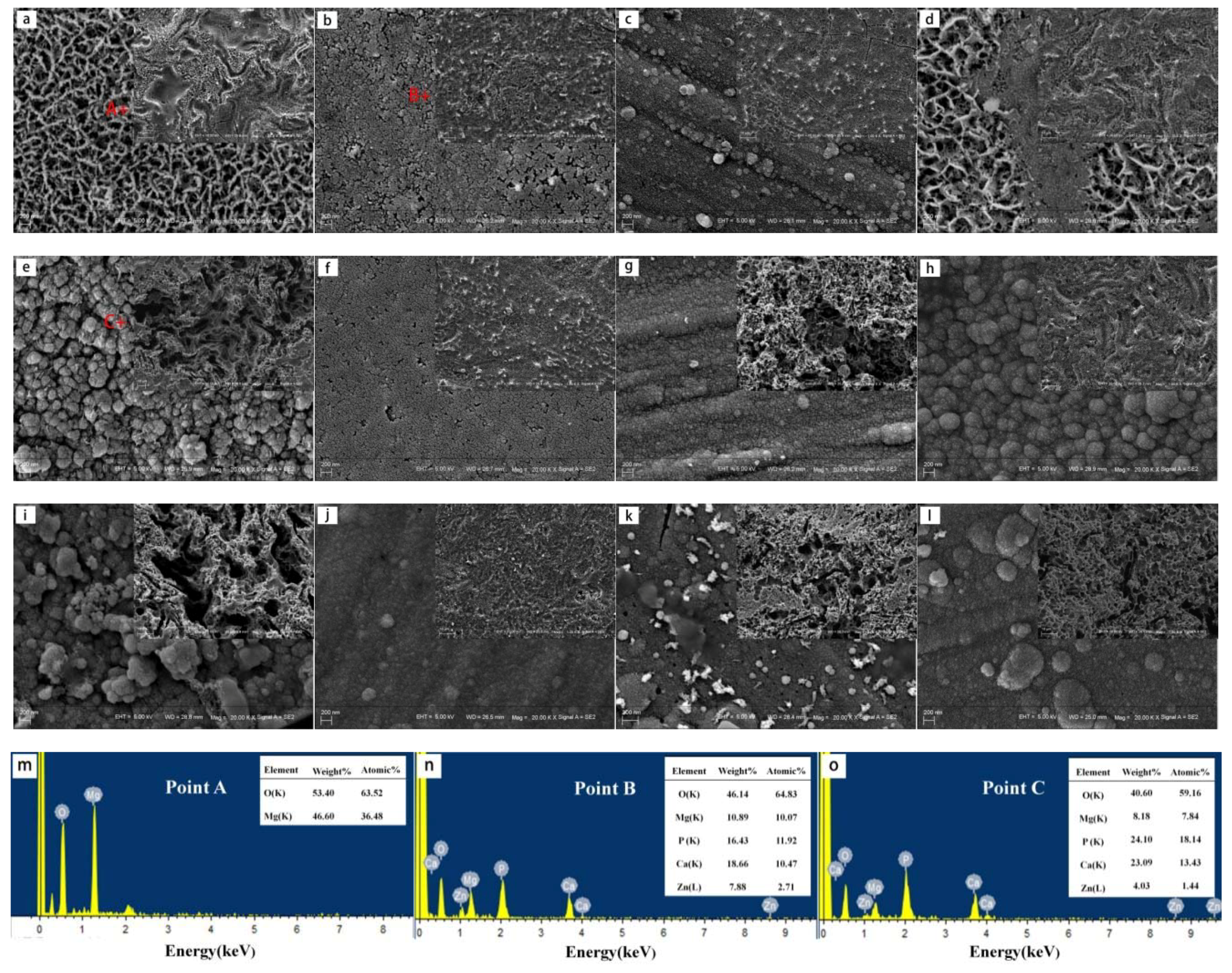
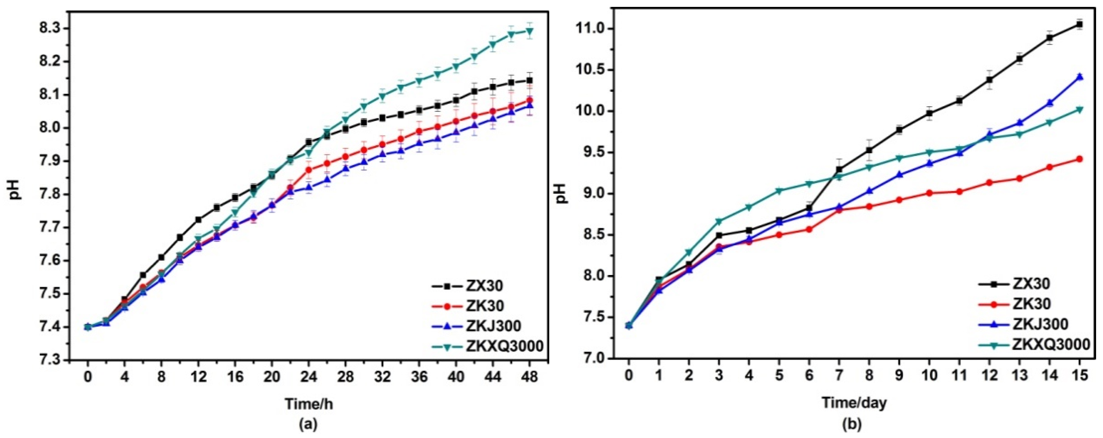
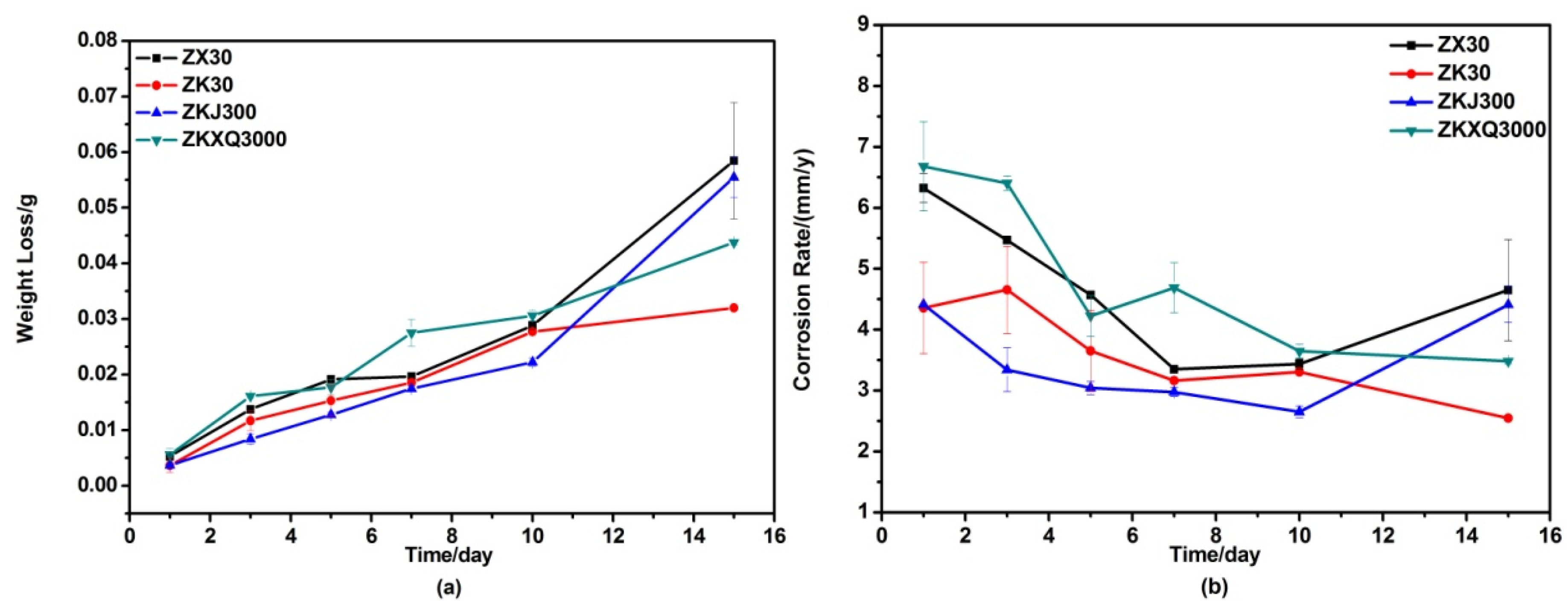
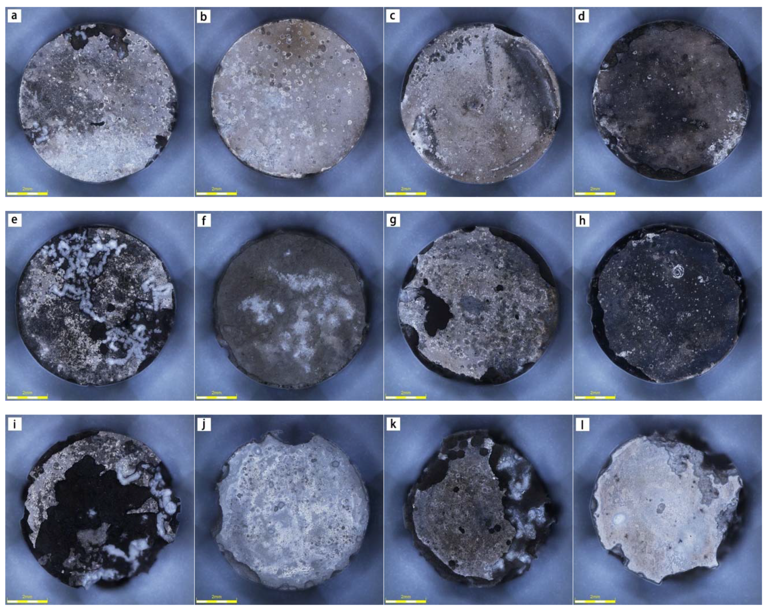
3.4. Immersion Testing In Vitro

Figure 8a shows the pH values of ZX30, ZK30, ZKJ300 and ZKXQ3000 alloys in simulated body fluid for the first 48 h. The pH values of ZX30, ZK30 and ZKJ300 alloys increased with a similar growth trend. Although the pH of ZKXQ3000 alloy in the initial stage was lower than that of ZX30, it increased at a faster rate, which exceeded that of ZX30 after immersion for 24 h. However, the pH values of the four alloys were changed dramatically during 15 days of immersion. The pH value of ZX30 alloy was the most prominent, and increased rapidly after 6 days (Figure 8b), until it reached 10.82 ± 0.06 after 15 days. The pH value of ZKJ300 increased gradually, exceeding that of ZKXQ3000 (10.02 ± 0.01) after 12 days, and the final pH was 10.48 ± 0.03. Variation about the pH value of ZK30 was the slowest, and the pH value was only 9.42 ± 0.03 after 15 days.
The change of pH value revealed that the corrosion rate of the mg alloys from slow to fast was ZK30, ZKXQ3000, ZKJ300, ZX30, successively. Meanwhile, the CR of as-extruded ZX30, ZK30, ZKJ300 and ZKXQ3000 alloys shown in Figure 9 were 4.649 ± 0.083 mm/y, 2.545 ± 0.132 mm/y, 4.410 ± 0.090 mm/y, 3.479 ± 0.036 mm/y, respectively. This was in agreement with the results of the 1/Rn curve.
The macroscopic images after removing the corrosion product are shown in the Figure 10. It can be seen that the edges of ZX30 and ZKXQ3000 peeled off, and the surfaces of ZK30 and ZKJ300 were relatively intact after one day of soaking. Moreover, the erosion of ZX30 after immersing for 5 d expanded to the middle of the sample from the edge, and the surface of ZKJ300 also appeared to be peeling in a large area, while the surfaces of ZKXQ3000 and ZK30 were still relatively smooth; only the edges were eroded. The corrosion of ZX30 and ZKJ300 was very high, and that of ZK30 was less compared with ZX30 and ZKJ300 after 15 days of immersion.

4. Discussion

4.1. Effects of Alloying Elements on Microstructure of ZX30, ZK30, ZKJ300 and ZKXQ3000 Alloys

Zirconium (Zr) is found to be more significant for grain refinement compared to the microstructure of ZX30 and ZK30 alloys, due to Zr providing numerous nucleation cores and not reacting with Mg to form a second phase. Meanwhile, Zr and Mg have the same hexagonal close packed crystal structures and a very close lattice constant, which greatly improves the nucleation rate of the alloy. It is also seen that the addition of Sr could further reduce the grain size of the ZK30 alloy from the microstructure of ZK30 and ZKJ300 alloys, due to the low solid solubility of Sr. When the alloy is solidified, the Sr would gather at the solid–liquid interface to inhibit the diffusion of the solute effectively, thus refining the size of the grain [32,33]. Compared with ZX30, ZK30 and ZKXQ3000, it reveals that Ca and Ag are also beneficial to promoting grain refinement, resulting in finer and more dispersive second phases. This is due to the stress concentration caused by the second phase of the deformation during the thermal deformation, and it leads to the dislocation entanglement and provides the nucleation sites for the dynamic recrystallization process, as a result of increasing the number of nucleation points and refining the grain.
Furthermore, the additions of Ca, Sr and Ag also have a great influence on the type and distribution of the secondary phase in magnesium alloys. Compared with ZKJ300 and ZX30 alloys, second phases of ZKXQ3000 are smaller and more dispersed. The reason is that the grain boundary density of ZKXQ3000 alloy is denser and more dislocations would be produced in the process of extrusion deformation, which produces higher energy and is beneficial to the nucleation of the second phase.

4.2. Effects of Alloying Elements on Mechanical Property of ZX30, ZK30, ZKJ300 and ZKXQ3000 Alloys

The tensile and compression strengths of ZKJ300 and ZKXQ3000 alloys are much higher than those of ZX30 and ZK30 alloys and this is probably due to the refinement of the grain and the appearance of relatively fine dispersion of the second phase. According to the Hall–Patch formula (σs = σ0 + kd−1/2, σs is the yield strength of the material, σ0 is the resistance to deformation in the crystal, k is the influence coefficient of grain boundary on deformation and d is average grain size); the smaller the grain size formed, the higher the strength obtained. The grain boundaries increase after grain refinement, the atoms on the grain boundaries are irregular, impurities and defects are large, and the energy is high, which hinder dislocation migration. Consequently, the finer and more uniform grain sizes result a higher yield strength of extruded ZKJ300 and ZKXQ3000 alloys. At the same time, there are more dispersed distribution of Mg-Zn, Mg17Sr2, Ca2Mg6Zn3 and Mg3Ag second phase in the as-extruded ZKJ300 and ZKXQ3000 alloys, and this can impede the dislocation movement in the deformation of the alloys, for enhancing its strength.
However, the elongations of ZKJ300 and ZKXQ3000 alloys are greatly reduced, because of the increase of the second phase and its movement to the grain boundary promoted by grain refinement. In this case, the dislocation congestion was increased when deforming, and then the more serious crack initiation was caused by the stress concentration at the grain boundary. Meanwhile, it can be seen that ZKJ300 and ZKXQ3000 alloys performed more dimples in Figure 4. The size and depth of dimples are related to the number and plasticity of the core of fracture materials. If the nucleation positions of the dimple are dense, the dimples formed in the fracture are small and shallow, and conversely, the positions of the dimple nucleation are less. For example, the larger and deeper dimples can be formed in single phase alloy with large grain size or pure metal. Therefore, the ZKJ300 and ZKXQ3000 alloys with smaller grain sizes and more second phase particles have smaller dimples, and the second phase particles of them can effectively obstruct the dislocation movement with higher tensile strength and lower plasticity.

4.3. Effects of Alloying Elements on the Corrosion Behaviors of ZX30, ZK30, ZKJ300 and ZKXQ3000 Alloys

Electrochemical noise is a random non-equilibrium fluctuation phenomenon to the electrical state parameters (electrode potential, external current density, etc.) in the evolution process of electrochemistry power system [34,35,36]. According to the change of the electrochemical noise fluctuation, the corrosion mechanism of magnesium alloy in different stages can be analyzed. As known, when Mg enters the simulated body fluid, corrosion occurs at the defects and the interface between the second phase and the matrix preferentially. The main reactions are as follows: Mg + H2O → Mg(OH)2 + H2, Mg(OH)2 + Cl → MgCl2 + OH. It can be observed from Figure 5 that the ZKXQ3000 has a large number of periodic transients in the initial stage of immersion, which is mainly related to the precipitation of hydrogen [37]. The current transient suddenly declining is due to adsorption of hydrogen on the sample surface reducing the anodic dissolution area, and playing a shielding effect, so that the current and potential noise are kept in a low range. The contact area between the solution and the sample increases, resulting in a sudden increase in the current and potential, when hydrogen reaches its critical value and breaks away from the surface. At this time, the transients of ZX30 and ZK30 are manifested by the decrease of potential noise and the increase of current noise, indicating pitting occurrence. With the increase of immersion, the noise current of ZK30 basically was stabilized at about 0, demonstrating that the surface passivation of ZK30 alloy inhibits further occurrence of corrosion.
The main reason for the difference of corrosion behavior of the alloys in the SBF is probably due to the effect of different alloying elements on the grain size of the magnesium alloy and the particle size and distribution of the second phase [25]. The severe reaction in the early stage of ZKXQ3000 is attributed to a large number of secondary phases, resulting in more induced points to galvanic corrosion. However, the corrosion resistance of ZKXQ3000 was not obviously reduced by corrosion morphology and weight loss test results, ascribed to the refinement of grain and grain boundary in the ZKXQ3000 alloy, performing more uniform corrosion. Furthermore, the second phases in the deformed alloy are mostly fine and dispersed continuously, which can form a protective film during the corrosion process. Although the corrosion layer and corrosion pits in the early stage of ZKJ300 are more compact and smaller, the corrosion resistance decreases obviously in the later period, which may be due to the second phase particles of ZKJ300 alloy being relatively coarse, and galvanic corrosion being the dominant factor in the late stage of corrosion. The ZX30 grains are large and the second phases are unevenly distributed, and thus the corrosion resistance is poor. ZK30 with the least amount of the second phases was not apt to be destroyed by local corrosion, so its corrosion resistance is the best of the four kinds of alloys.
The corrosion behavior of the Mg alloys can be summarized as follows: Mg reacts with water to form Mg(OH)2 and H2, and the surface gradually forms a flaky Mg(OH)2 film. Then, the SBF solution can continue to react with the substrate to produce Mg(OH)2 through the porous flaky membrane, while Cl in the SBF solution dissolves part of the Mg(OH)2, thus exposing the new alloy matrix to be eroded. Therefore, the relatively weak Mg(OH)2 film in the early phase is at a dynamic dissolution and deposition equilibrium state [15]. As the degradation process continues, the partial phosphoric acid in the SBF solution is dissociated and reacts with the Mg2+, Ca2+ and OH in the solution to produce various refractory phosphate and then cover the surface of the Mg(OH)2 film [38], which protects the alloy matrix.

5. Conclusions

The effects of biological functional elements (Ca, Sr, Zr, Ag) on the comprehensive properties of four kinds of as-extruded magnesium alloys (ZX30, ZK30, ZKJ300 and ZKXQ3000) were studied. The additions of alloying elements result in the refinement of alloy grains and the production of second phase particles of different size and distribution, which affects the performance of alloys in mechanics and corrosion. According to tensile and compression tests, the strength of ZKJ300 and ZKXQ3000 alloys were significantly improved, attributed to the pinning effect of the second phase particles. Based on the electrochemical noise and immersion tests, both ZK30 and ZKXQ3000 exhibited good corrosion resistance. All the magnesium alloys showed obvious differences of mechanical and corrosion behaviors. It can be found that the overall performance of ZKXQ3000 is the best, which can be applied to bone fracture sites requiring strong load-bearing capability.

Supplementary Materials

Supplementary File 1

Author Contributions

Conceptualization, M.C.; Data curation, G.L.; Formal analysis, G.L.; Investigation, G.L.; Methodology, G.L. and M.C.; Resources, M.C.; Supervision, M.C.; Writing—original draft, G.L.; Writing—review and editing, G.L., M.C., Y.Z., Y.S. and D.T.

Funding

This research was funded by Key projects of the Joint Foundation of the National Natural Science Foundation of China (U1764254), Major science and technology projects in Tianjin (No. 15ZXQXSY00080).

Acknowledgments

The authors acknowledge Surface Engineering Group at University of Wollongong in Australia.

Conflicts of Interest

The authors declare no conflict of interest. The founding sponsors had no role in the design of the study; in the collection, analyses, or interpretation of data; in the writing of the manuscript, and in the decision to publish the results.

References

  1. Staiger, M.P.; Pietak, A.M.; Huadmai, J.; Dias, G. Magnesium and its alloys as orthopedic biomaterials: A review. Biomaterials 2006, 27, 1728–1734. [Google Scholar] [CrossRef] [PubMed]
  2. Li, X.; Liu, X.; Wu, S.; Yeung, K.W.K.; Zheng, Y.; Chu, P.K. Design of magnesium alloys with controllable degradation for biomedical implants: From bulk to surface. Acta Biomater. 2016, 45, 2–30. [Google Scholar] [CrossRef] [PubMed]
  3. Singh Raman, R.K.; Jafari, S.; Harandi, S.E. Corrosion fatigue fracture of magnesium alloys in bioimplant applications: A review. Eng. Fract. Mech. 2015, 137, 97–108. [Google Scholar] [CrossRef]
  4. Aghion, E.; Levy, G.; Ovadia, S. In vivo behavior of biodegradable Mg-Nd-Y-Zr-Ca alloy. J. Mater. Sci. Mater. Med. 2012, 23, 805–812. [Google Scholar] [CrossRef] [PubMed]
  5. Pichler, K.; Fischerauer, S.; Ferlic, P.; Martinelli, E.; Brezinsek, H.P.; Uggowitzer, P.J.; Löffler, J.F.; Weinberg, A.M. Immunological Response to Biodegradable Magnesium Implants. JOM 2014, 66, 573–579. [Google Scholar] [CrossRef]
  6. Razavi, M.; Fathi, M.; Savabi, O.; Razavi, S.M.; Heidari, F.; Manshaei, M.; Vashaee, D.; Tayebi, L. In vivo study of nanostructured diopside (CaMgSi2O6) coating on magnesium alloy as biodegradable orthopedic implants. Appl. Surf. Sci. 2014, 313, 60–66. [Google Scholar] [CrossRef]
  7. Li, H.; Zheng, Y.; Qin, L. Progress of biodegradable metals. Prog. Nat. Sci. Mater. Int. 2014, 24, 414–422. [Google Scholar] [CrossRef] [Green Version]
  8. Gu, X.; Zheng, Y.; Cheng, Y.; Zhong, S.; Xi, T. In vitro corrosion and biocompatibility of binary magnesium alloys. Biomaterials 2009, 30, 484–498. [Google Scholar] [CrossRef] [PubMed]
  9. Zhang, Y.; Li, J.; Li, J. Microstructure, mechanical properties, corrosion behavior and film formation mechanism of Mg-Zn-Mn-xNd in Kokubo’s solution. J. Alloys Compd. 2018, 730, 458–470. [Google Scholar] [CrossRef]
  10. Liu, Y.; Wu, Y.; Bian, D.; Gao, S.; Leeflang, S.; Guo, H.; Zheng, Y.; Zhou, J. Study on the Mg-Li-Zn ternary alloy system with improved mechanical properties, good degradation performance and different responses to cells. Acta Biomater. 2017, 62, 418–433. [Google Scholar] [CrossRef] [PubMed]
  11. Wang, W.; Han, J.; Yang, X.; Li, M.; Wan, P.; Tan, L.; Zhang, Y.; Yang, K. Novel biocompatible magnesium alloys design with nutrient alloying elements Si, Ca and Sr: Structure and properties characterization. Mater. Sci. Eng. B 2016, 214, 26–36. [Google Scholar] [CrossRef]
  12. Mendis, C.L.; Oh-ishi, K.; Hono, K. Enhanced age hardening in a Mg–2.4 at.% Zn alloy by trace additions of Ag and Ca. Scr. Mater. 2007, 57, 485–488. [Google Scholar] [CrossRef]
  13. Aral, H.; Vecchio-Sadus, A. Toxicity of lithium to humans and the environment-A literature review. Ecotoxicol. Environ. Saf. 2008, 70, 349–356. [Google Scholar] [CrossRef] [PubMed]
  14. Ding, D.; Roth, J.; Salvi, R. Manganese is toxic to spiral ganglion neurons and hair cells in vitro. Neurotoxicology 2011, 32, 233–241. [Google Scholar] [CrossRef] [PubMed] [Green Version]
  15. Agarwal, S.; Curtin, J.; Duffy, B.; Jaiswal, S. Biodegradable magnesium alloys for orthopaedic applications: A review on corrosion, biocompatibility and surface modifications. Mater. Sci. Eng. C 2016, 68, 948–963. [Google Scholar] [CrossRef] [PubMed] [Green Version]
  16. Zhang, B.; Hou, Y.; Wang, X.; Wang, Y.; Geng, L. Mechanical properties, degradation performance and cytotoxicity of Mg–Zn–Ca biomedical alloys with different compositions. Mater. Sci. Eng. C 2011, 31, 1667–1673. [Google Scholar] [CrossRef]
  17. Li, Y.; Hodgson, P.D.; Wen, C.E. The effects of calcium and yttrium additions on the microstructure, mechanical properties and biocompatibility of biodegradable magnesium alloys. J. Mater. Sci. 2011, 46, 365–371. [Google Scholar] [CrossRef]
  18. StJohn, D.H.; Qian, M.; Easton, M.A.; Cao, P.; Hildebrand, Z. Grain refinement of magnesium alloys. Metall. Mater. Trans. A 2005, 36, 1669–1679. [Google Scholar] [CrossRef]
  19. Cheng, M.; Chen, J.; Yan, H.; Su, B.; Yu, Z.; Xia, W.; Gong, X. Effects of minor Sr addition on microstructure, mechanical and bio-corrosion properties of the Mg-5Zn based alloy system. J. Alloys Compd. 2017, 691, 95–102. [Google Scholar] [CrossRef]
  20. Li, R.G.; Xin, R.L.; Liu, Q.; Liu, J.A.; Fu, G.Y.; Zong, L.; Yu, Y.M.; Guo, S.G. Effect of Ag addition on microstructure and mechanical properties of Mg–14Gd–0.5Zr alloy. Mater. Charact. 2015, 109, 43–49. [Google Scholar] [CrossRef]
  21. Du, Y.Z.; Qiao, X.G.; Zheng, M.Y.; Wang, D.B.; Wu, K.; Golovin, I.S. Effect of microalloying with Ca on the microstructure and mechanical properties of Mg-6 mass%Zn alloys. Mater. Des. 2016, 98, 285–293. [Google Scholar] [CrossRef]
  22. Huang, X.; Du, Y.; Li, W.; Chai, Y.; Huang, W. Effects of Ag content on the solid-solution and age-hardening behavior of a Mg-5Sn alloy. J. Alloys Compd. 2017, 696, 850–855. [Google Scholar] [CrossRef]
  23. Huang, X.; Wu, A.; Li, Q.; Huang, W. Effects of extrusion and Ag, Zn addition on the age-hardening response and microstructure of a Mg-7Sn alloy. Mater. Sci. Eng. A 2016, 661, 233–239. [Google Scholar] [CrossRef]
  24. L, W.; Huang, X.; Huang, W. Effects of Ca, Ag addition on the microstructure and age-hardening behavior of a Mg-7Sn (wt%) alloy. Mater. Sci. Eng. A 2017, 692, 75–80. [Google Scholar] [CrossRef]
  25. Radha, R.; Sreekanth, D. Insight of magnesium alloys and composites for orthopedic implant applications—A review. J. Magnes. Alloys 2017, 5, 286–312. [Google Scholar] [CrossRef]
  26. Zhao, D.; Witte, F.; Lu, F.; Wang, J.; Li, J.; Qin, L. Current status on clinical applications of magnesium-based orthopaedic implants: A review from clinical translational perspective. Biomaterials 2017, 112, 287–302. [Google Scholar] [CrossRef] [PubMed]
  27. Zhao, D.; Huang, S.; Lu, F.; Wang, B.; Yang, L.; Qin, L.; Yang, K.; Li, Y.; Li, W.; Wang, W.; et al. Vascularized bone grafting fixed by biodegradable magnesium screw for treating osteonecrosis of the femoral head. Biomaterials 2016, 81, 84–92. [Google Scholar] [CrossRef] [PubMed]
  28. Lee, J.W.; Han, H.S.; Han, K.J.; Park, J.; Jeon, H.; Seok, H.K.; Ahn, J.P.; Lee, K.E.; Lee, D.H.; Yang, S.J.; et al. Long-term clinical study and multiscale analysis of in vivo biodegradation mechanism of Mg alloy. Proc. Natl. Acad. Sci. USA 2016, 113, 716–721. [Google Scholar] [CrossRef] [PubMed]
  29. Li, Z.; Chen, M.; Li, W.; Zheng, H.; You, C.; Liu, D.; Jin, F. The synergistic effect of trace Sr and Zr on the microstructure and properties of a biodegradable Mg-Zn-Zr-Sr alloy. J. Alloys Compd. 2017, 702, 290–302. [Google Scholar] [CrossRef]
  30. Li, Z.; Sun, S.; Chen, M.; Fahlman, B.D.; Liu, D.; Bi, H. In vitro and in vivo corrosion, mechanical properties and biocompatibility evaluation of MgF2-coated Mg-Zn-Zr alloy as cancellous screws. Mater. Sci. Eng. C 2017, 75, 1268–1280. [Google Scholar] [CrossRef] [PubMed]
  31. Wang, J.; Jiang, H.; Bi, Y.; Sun, J.; Chen, M.; Liu, D. Effects of gas produced by degradation of Mg-Zn-Zr Alloy on cancellous bone tissue. Mater. Sci. Eng. C 2015, 55, 556–561. [Google Scholar] [CrossRef] [PubMed]
  32. Lee, Y.C.; Dahle, A.K.; Stjohn, D.H. The role of solute in grain refinement of magnesium. Metall. Mater. Trans. A 2000, 31, 2895–2906. [Google Scholar] [CrossRef]
  33. Wang, D.; Gao, J.; Zhang, J.; Li, Y.; Li, Z. Manipulation of squeezed state in electromagnetically induced transparency system via dynamic Stark effect. J. Opt. Soc. Am. B 2012, 29, 3177–3182. [Google Scholar] [CrossRef]
  34. Casajús, P.; Winzer, N. Electrochemical noise analysis of the corrosion of high-purity Mg–Al alloys. Corros. Sci. 2015, 94, 316–326. [Google Scholar] [CrossRef]
  35. Jamali, S.S.; Mills, D.J. A critical review of electrochemical noise measurement as a tool for evaluation of organic coatings. Prog. Org. Coat. 2016, 95, 26–37. [Google Scholar] [CrossRef] [Green Version]
  36. Curioni, M.; Cottis, R.A.; Di Natale, M.; Thompson, G.E. Corrosion of dissimilar alloys: Electrochemical noise. Electrochim. Acta 2011, 56, 6318–6329. [Google Scholar] [CrossRef]
  37. Zhang, T.; Shao, Y.; Meng, G.; Wang, F. Electrochemical noise analysis of the corrosion of AZ91D magnesium alloy in alkaline chloride solution. Electrochim. Acta 2007, 53, 561–568. [Google Scholar] [CrossRef]
  38. Zhang, S.; Li, J.; Song, Y.; Zhao, C.; Zhang, X.; Xie, C.; Zhang, Y.; Tao, H.; He, Y.; Jiang, Y.; et al. In Vitro degradation, hemolysis and MC3T3-E1 cell adhesion of biodegradable Mg–Zn alloy. Mater. Sci. Eng. C 2009, 29, 1907–1912. [Google Scholar] [CrossRef]
Figure 1. Metallographs of as-extruded ZX30 (a), ZK30 (b), ZKJ300 (c) and ZKXQ3000 (d) alloys.
Crystals 08 00271 g001
Figure 2. The XRD patterns of as-extruded ZX30, ZK30, ZKJ300 and ZKXQ3000 alloys.
Crystals 08 00271 g002
Figure 3. Mechanical properties of as-extruded ZX30, ZK30, ZKJ300 and ZKXQ3000 alloys. (a) tensile and (b) compression stress-strain curves of four alloys.
Crystals 08 00271 g003
Figure 4. Fracture surface morphologies of the as-extruded ZX30 (a,e,i,m), ZK30 (b,f,j,n), ZKJ300 (c,g,k,o), ZKXQ3000 (d,h,l,p) alloys. (ah) tensile, (ip) compression fracture surface morphology of the four alloys.
Crystals 08 00271 g004aCrystals 08 00271 g004b
Figure 5. General appearance current and potential time records for ZX30 (a1a8), ZK30 (b1b8), ZKJ300 (c1c8), ZKXQ3000 (d1d8) immersed in SBF for 0 h (a1,b1,c1,d1), 2 h (a2,b2,c2,d2), 1 d (a3,b3,c3,d3), 3 d (a4,b4,c4,d4), 5 d (a5,b5,c5,d5), 7 d (a6,b6,c6,d6), 10 d (a7,b7,c7,d7), 15 d (a8,b8,c8,d8) after DC trend removal.
Crystals 08 00271 g005aCrystals 08 00271 g005bCrystals 08 00271 g005c
Figure 6. The inverse of noise resistance, Rn, of ZX30, ZK30, ZKJ300 and ZKXQ3000 alloys.
Crystals 08 00271 g006
Figure 7. The SEM images of corrosion morphology of ZX30 (a,e,i), ZK30 (b,f,j), ZKJ300 (c,g,k), ZKXQ3000 (d,h,l) alloys immersing for 1 d (ad), 5 d (ef) and 15 d (il) and EDS images of point A (m), point B (n), point C (o). The SEM images of corrosion morphology of ZX30, ZK30, ZKJ300 and ZKXQ3000 alloys after removing the corrosion products are on the upper right corner of figure (al).
Crystals 08 00271 g007
Figure 8. The pH values of the as-extruded ZX30, ZK30, ZKJ300 and ZKXQ3000 alloys immersed for different time. (a) pH value of the first 48 h; (b) pH value of 15 days.
Crystals 08 00271 g008
Figure 9. Weight loss (a) and corrosion rate (b) curves of the as-extruded ZX30, ZK30, ZKJ300 and ZKXQ3000 alloys immersed in SBF for different days.
Crystals 08 00271 g009
Figure 10. The macroscopic images after removing the corrosion product of the as-extruded ZX30 (a,e,i), ZK30 (b,f,j), ZKJ300 (c,g,k), ZKXQ3000 (d,h,l) alloys immersing for 1 d (ad), 5 d (ef) and 15 d (il).
Crystals 08 00271 g010
Table 1. Mechanical properties of as-extruded ZX30, ZK30, ZKJ300 and ZKXQ3000 alloys.
YTS (MPa)UTS (MPa)EL (%)YCS (MPa)UCS (MPa)
ZX30262.67 ± 4.10298.17 ± 0.9318.33 ± 0.67256.70 ± 0.94361.32 ± 9.52
ZK30246.00 ± 6.81293.26 ± 2.7120.00 ± 2.31296.49 ± 2.76342.62 ± 6.29
ZKJ300301.33 ± 2.40334.61 ± 2.9213.33 ± 1.33315.69 ± 0.78359.78 ± 2.93
ZKXQ3000315.33 ± 5.67337.56 ± 2.1914.67 ± 1.76279.16 ± 3.06354.45 ± 11.27

