Polarization Converter Based on Square Lattice Photonic Crystal Fiber with Double-Hole Units


1
Department of Electrical, Electronics and Information Engineering, Kanagawa University, Yokohama 221-8686, Japan
2
Division of Information and Electronic Engineering, Muroran Institute of Technology, Muroran 050-8585, Japan
3
Department of Opt-Electronic System Engineering, Chitose Institute of Science and Technology, Chitose 066-8655, Japan
*
Author to whom correspondence should be addressed.
†
Current address: 3-27-1 Rokkakubashi, Kanagawa-ku, Yokohama 221-8686, Japan.
Crystals 2019, 9(2), 58; https://doi.org/10.3390/cryst9020058
Submission received: 17 December 2018
/
Revised: 18 January 2019
/
Accepted: 21 January 2019
/
Published: 22 January 2019
(This article belongs to the Special Issue Sonic and Photonic Crystals)
Abstract
:In this study, a novel polarization converter (PC) based on square lattice photonic crystal fiber (PCF) is proposed and analyzed. For each square unit in the cladding, two identical circular air holes are arranged symmetrically along the axis. With the simple configuration structure, numerical simulations using the FDTD analysis demonstrate that the PC has a strong polarization conversion efficiency (PCE) of 99.4% with a device length of 53 m, and the extinction ratio is −21.8 dB. Considering the current PCF fabrication technology, the structural tolerances of circular hole size and hole position have been discussed in detail. Moreover, it is expected that over the 1.2∼1.7 m wavelength range, the PCE can be designed to be better than 99% and the corresponding extinction ratio is better than .
1. Introduction
With the rapid development of Internet, high frequency communication systems have been widely studied to realize the next-generation advanced communication system. Among several means of communication, the optical communication system attracts a lot of attention since it can achieve a high-speed and large-capacity data transmission. In recent years, studies on special optical fibers and high-performance optical devices promote the performance of optical communication system. Photonic crystal fiber (PCF) [1,2] is a newly emerging optical fiber with a periodic arrangement of microscopic air holes running along the fiber axis in the cladding region. For this kind of fiber, the refractive index of cladding can be easily controlled by adjusting the geometry and distribution of the holes. In comparison to conventional optical fiber, PCF shows basic properties like birefringence, nonlinearity and single-polarization transmission that can be tailored to achieve extraordinary outputs [3,4,5].
Polarization converters (PCs) [6,7,8,9,10,11,12,13,14,15,16,17,18,19,20] plays an important role in the modern communication systems and photonic integrated circuits, such as polarization division multiplexing systems [21], polarization diversity systems [22], and polarization switches [23]. Until now, several approches have been used to design PCs, which can be classified into two types. The first type is using the mode interference. The waveguide has a high birefringent core by using asymmetrical cross section, liquid crystal or with hybrid plasmonic. Two orthogonal guided modes are excited and beat together rhythmically with the light propagation. Polarization conversion can be achieved when the two guided modes accumulate a -phase shift after undergoing each beat length. The second type of approach is on the basis of mode coupling. In this approach, at least two waveguides are used. Utilzing the birefringence of the input waveguide, the specified polarization mode is coupled and converted into the adjacent output waveguide by satisfying the phase matching condition. In contrast, another polarization mode in the input waveguide will keep propagating along because of the significant effective index difference between the two waveguides, resulting in very weak coupling. According to these two design mechanisms, plenty of PCs have been proposed based on waveguides or fibers. So far, several kinds of PCF based fiber type PCs have been designed by using a liquid crystal core [11,12,13,14], asymmetric core [15,16], plasmonic core [18] and elliptical hole core [19], etc. M. Hameed et al. proposed two kinds of PCs using a liquid crystal core [12,13,14] and an asymmetric core [15,16], respectively. Although these PCs can achieve a high polarization conversion efficiency (PCE) and a low extinction ratio (ER), the temperature dependence of liquid crystals and the non-Gaussian field distribution caused by the asymmetric structures limit the application of these PCs. L. Chen et al. designed a PC based on hybrid plasmonic PCF in 2014. The PC offers a 93% PCE with a device length of 163 m. However, the PC suffers from a quite high insertion loss due to the use of metal copper. After then, in 2016, Z. Zhang et al. proposed a cross-talk free PC with a symmetric distribution using several tilted elliptical air holes in the core region [19]. Almost 100% PCE is achieved with a compact device length of only 31.7 m. Whereas, it suffering a low structural tolerance due to the difficulty of producing elliptical holes in the PCF. Consequently, the use of different air hole shapes or multiple materials increases the manufacturing difficulties and leads to a low structural tolerance. Therefore, in designing a fiber type PC, in addition to achieve a high PCE and a low ER, a Gaussian-like field distribution and a large structural tolerance are also essential.
In this study, a novel PC element based on a square lattice PCF with a simple configuration structure is reported and analyzed. Since only one type of circular air hole is adopted to consist the PC, it can be easily fabricated with the method of stack and draw [24]. The setting of geometric parameters and the light propagation behavior are illustrated in the next section. After that, considering the current PCF fabrication technology, the structural tolerances of the circular air hole size and air hole position have been discussed in detail. Moreover, the wavelength dependence of the proposed PC has also given in Section 3. In this study, the full-vectorial finite-element method (FV-FEM) and finite-difference time-domain (FDTD) method have been used to estimate the modal effective index and the light propagation, respectively.
2. Square Lattice PC with Double-Hole Unit
2.1. Design of Square Lattice PC
In this section, a PC with double-hole unit cells in the cladding is illustrated. Figure 1 shows the cross section of our proposed PC based on a square lattice PCF. The light blue region and white circular area represent the background material and air holes, respectively. The square lattice pitch refers to . For each unit cell, which is represented with red wire frame, two air holes (with the diameter ) are arranged symmetrically along the diagonal. The distance between the center of two air holes is represented by . The angle is 45 degrees. In the periodic lattice component, one defect is introduced to confine the light as the core region. Due to the symmetrical distribution along , the polarization conversion can be achieved using two excited hybrid modes that are polarized in the directions with respect to the x axis.
According to the phase matching condition, the conversion length is defined as
where is the operation wavelength and and are the effective indices of fundamental and 1st-higher-order modes, respectively. As an incident light travels to L along the z direction, the PCE of a PC, which is an important performance indicator, is defined as follows [10]:
where the rotation angle is defined by the fundamental mode field:
Here, is the refractive-index distribution, and and are the non-domain and domain magnetic fields of the fundamental mode, respectively. The modal hybrid, which is represented by R in Equation (3), is a quantity between 0 and 1. Therefore, results in a PCE of 100% at .
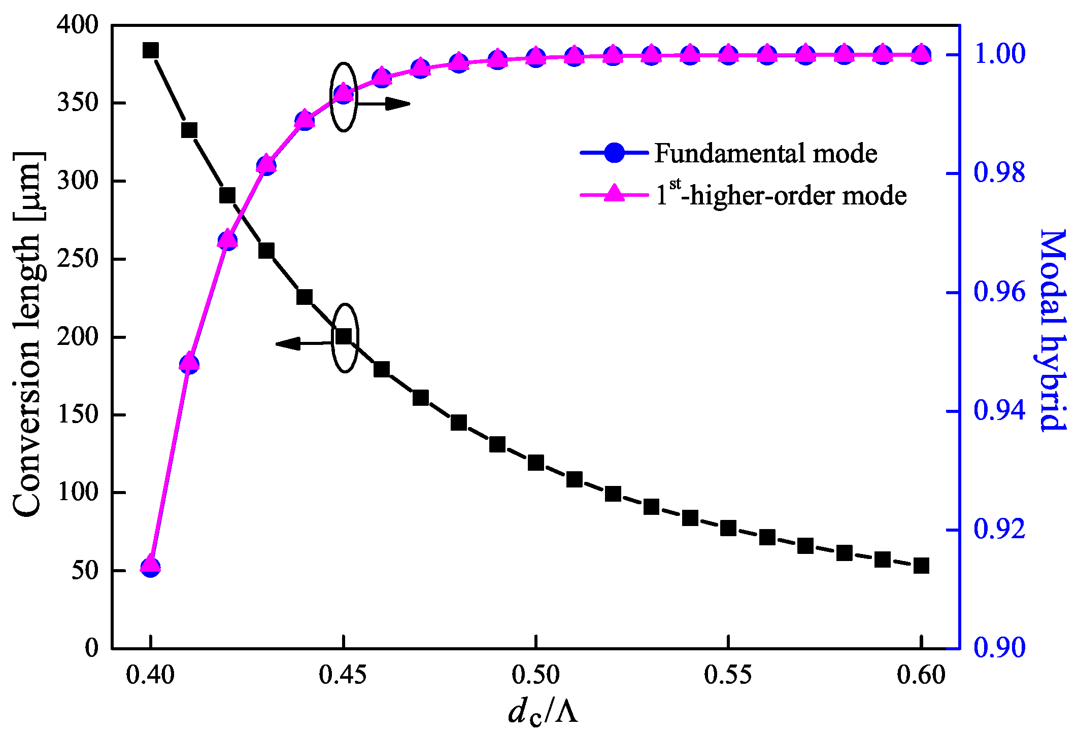
The variation of conversion length with different geometric parameters is investigated at a wavelength of 1.55 m, as illustrated in Figure 2. Here, the refractive indices of and air are 1.45 and 1, respectively, the lattice pitch is set to m. Simulation results using FV-FEM demonstrate that under these conditions, only two modes (the fundamental mode and the 1st-higher-order mode) are excited to dominate the polarization behavior. The parameter represents the horizontal distance between the center of air hole and the lattice for each unit cell. It is revealed that the PC has a shorter conversion length with a larger cladding hole size. Additionally, the variation of parameter has a small effect on the PC conversion length with a large hole size. In particularly, for , the conversion length is almost unaffected by the . In this case, considering that adjacent air holes on the same diagonal direction cannot overlap with each other, therefore, the parameter between 0.22 to 0.28 has been investigated to make the PC manufacturable. In this paper, the is fixed to 0.25, i.e., the hole gap . Moreover, the modal hybrids of fundamental and 1st-higher-order modes with different hole sizes have also been discussed. From Figure 3, as increasing the from 0.4 to 0.6, the conversion length decreases from 384 m to m, while the fundamental and 1st-higher-order modes have almost the same modal hybrid which are increasing from 0.914 to almost 1.000. It is evident from this figure that the values of R are better than 0.999 for .
Figure 4a–d show the magnetic field distributions of and components for fundamental and 1st-higher-order modes with at a wavelength of 1.55 m. It is apparent that each mode has almost the same magnetic field distributions, and the numerical results reveal that the modal hybrid is 0.999995 for the fundamental mode and 0.999996 for the 1st-higher-order mode. The light propagation behavior through the PC with m is shown in Figure 5. The 3D FDTD method with a grid size of m and m has been adopted in this investigation. The obtained normalized power against the propagation length is given in Figure 6. It is obvious that with a TM mode launched into the PC, it can be completely converted into the TE mode at m. In addition, the calculated PCE is better than 99.4% and the ER is better than −21.1 dB.
2.2. Gaussian-Like Field Distribution of the PC
Considering the connection between a PC element and a conventional single-mode fiber (SMF), a Gaussian-like field distribution of a PC is necessary to suppress the insertion loss. Unlike previous studies using the asymmetric core distributions, our proposed PC can easily offer a Gaussian-like electromagnetic field distribution. In this study, we measure the mode matching ratio (MMR) between the fundamental mode of the PC and a Gaussian field distribution using the following overlap integral:
where is the field distribution of fundamental mode. The Gaussian field distribution is represented by the as follows,
where is the standard deviation of . Moreover, the spot size of a Gaussian field distribution, which is illustrated by w, is the diameter at which the light intensity drops to of its maximum value. The spot size is calculated by . The maximum value of MMR between an excited fundamental mode of the PC and an appropriate Gaussian field distribution can be obtained by adjusting the value of . Table 1 illustrates the maximum MMR of each fundamental mode with an appropriate Gaussian field distribution (the corresponding spot size is illustrated under each MMR). According to the calculated results, the excited modes of the proposed PC show quite a great agreement with Gaussian field distributions. Therefore, we believe our proposed PC has a great potential to be used with a low insertion loss.
3. Structural Tolerance and Wavelength Dependence
So far, the propagation property of the PC with double-hole unit has been investigated. Compared to the previously proposed PCF based PCs [11,12,13,14,15,16,17,18,19,20], the optical device in this study has almost the same level of a high PCE and a low ER. However, the PC element with only one kind of circular air holes is the most prominent feature of this study. The simple structure distribution reduces the manufacturing difficulty and enlarges the structural tolerance simultaneously. Considering the current PCF fabrication technology, the structural tolerance should be discussed. In this study, we discuss the tolerances of hole size and hole position by investigating the variation of PCE, respectively. Additionally, the wavelength dependence of the PC has also been discussed. According to the calculation formula of the PCE in Equation (2), for a designed PC element, the modal hybrid (R) and the difference between the fixed device length (L) and the conversion length () are two primery factors affecting the final PCE. Therefore, the variation of parameters R and with different conditions (the deviation of hole size, change of hole position or variation of operation wavelength) should be taken into account.
3.1. Tolerance of Cladding Hole Size
Firstly, the structural tolerance of hole size in the PC has been investigated. The variations of parameters and R against the hole diameter with different deviation levels have been discussed and illustrated in Figure 7. Here, we claim that the fixed device length for each case is the completely conversion length of the PC with designed air hole sizes, i.e., m for , m for , m for , and m for . It is revealed from Figure 7 that with the deviation of from −1.5% to 1.5%, the modal hybrids for 0.5, 0.55, and 0.6 remain almost 1.000. Therefore, the final PCEs are mainly dependent on the value of . On the contrary, for the , the parameter R increases from 0.991 to 0.996, and the variation of difference between the fixed device length and the conversion length is also relatively large. Consequently, the PCE is effected by the modal hybrid and the difference between L and simultaneously.
Figure 8 is the contour map of the PCE as a function of the deviation of hole diameter with different hole sizes from 0.4 to 0.6. The contour line with a PCE of 99% is represented by a dash-dotted line. Simulation results reveal that within the deviation range of ±1.5%, the PC with a larger cladding hole size has a wider tolerance range to achieve the PCE better than 99%. In particularly, for 0.6, the corresponding tolerance range is ±1.5% (±9.0 nm), which is 7 times as larger as that of the PC in [19]. Therefore, we believe that a simple structure PC with a relative large tolerance is achieved.
3.2. Tolerance of Cladding Hole Position
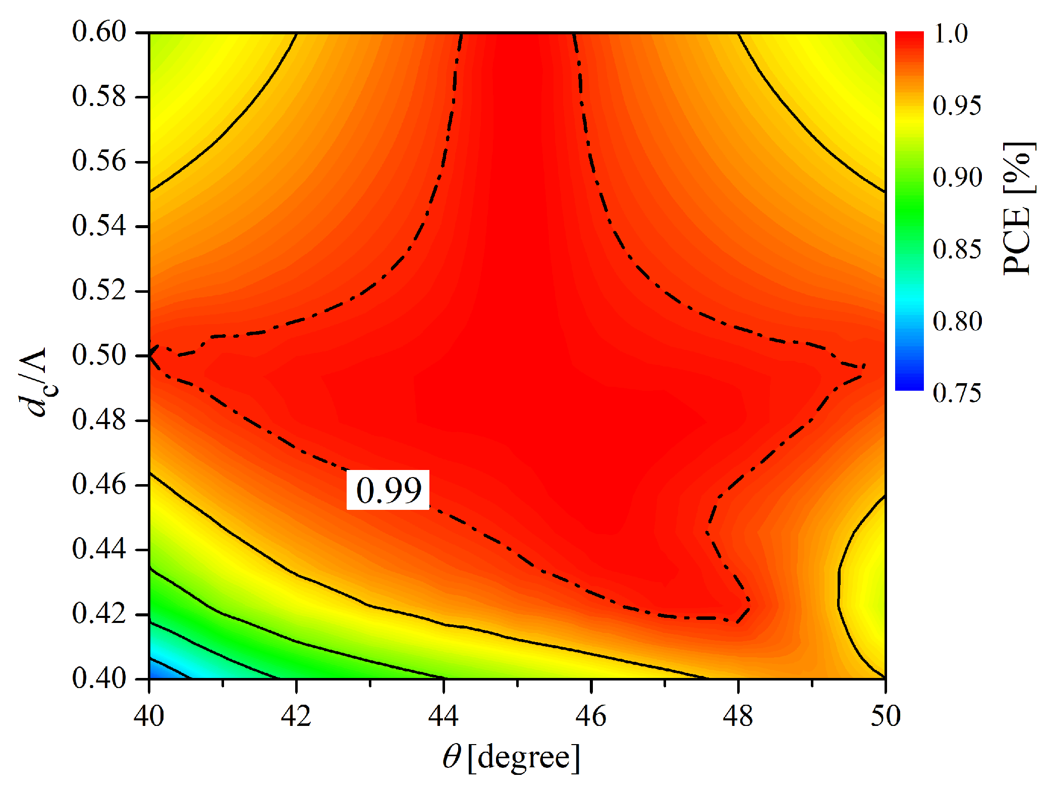
Then, the tolerance of circular hole position in each unit cell is investigated. The square lattice PC with a symmetric structure along axis makes the angle between the modal optical axis and the horizontal axis to be 45 degrees. In this study, two circular air holes are arranged symmetrically along the diagonal for each unit cell to achieve the highest PCE. However, the positions of the circular holes will be slightly varied during the actual production process. The slight asymmetrical distribution of cladding holes results in a decrease of the modal hybrid. Here, we investigated the variation of PCE against the parameter with a constant hole gap of . The variations of the two major factors have been investigated with different rotation angles from 40 to 50 degrees, as illustrated in Figure 9. The fixed device length for each hole size is the same as previously. For the variation of , the differences increase as the angle deviates from 45 degrees. Additionally, for the variation of modal hybrid, the parameter R reaches the maximum value at for 0.5, 0.55 and 0.6, and the value gradually decreases as the angle varied. It is worth noting that the PC with a larger hole size has a stronger angle dependence. This is because the light is mainly confined in the core, and a larger cladding hole size leads to a stronger light confinement. Therefore, the light confinement region in the core has a strong dependence on the positions of first layer air holes in the cladding. A slight angle variation of the first layer holes may lead to a change in modal hybrid of excited modes. On the other hand, for a PC with 0.45, the light confinement is relatively weak. Moreover, as the result shown in Figure 3, the corresponding modal hybrid is lower than 1.00 at . While for the simulation result in Figure 9, it is noted that the maximum value of modal hybrid exists at . Therefore, for PC with a small hole sizes, the maximum value of the PCE will shift in the direction of larger than 45 degrees.
Considering the two major factors, the variation of PCE against the parameter has been discussed and illustrated in Figure 10. The contour line with a PCE of 99% is represented by a dash-dotted line. It is evident that the PCE of a PC with a cladding hole size around is better than 99% for from 40 to 49 degrees. For the PC hole size larger than , the corresponding angle range decreases, and the maximum value of PCE remains at 45 degrees. While for the , the maximum value of PCE gradually shifts to a large rotation angle, which is in agreement with the aforementioned analysis.
3.3. Wavelength Dependence
In order to confirm the wide-band transmission, the wavelength dependence of our proposed PC has also been discussed in detail. It is worth to note that more than two modes are excited for the PC with a short operation wavelength. Although other higher-order modes appear at a short wavelength (such as a wavelength range of 1.2∼1.45 m for the PC with ), the incident light of the FDTD simulation is only using the fundamental and the 1st-higher-order modes. Simulation results show that the other higher-order modes are not excited during the light propagation. Therefore, the effect of other modes on the polarization behavior is negligible. The variations of the difference between device length and conversion length, and the modal hybrid with different operation wavelengths are respectively illustrated in Figure 11. According to the simulation results, since the conversion length of the PC increases with wavelengths, the value of varies from positive to negative as the wavelength changes from 1.2 to 1.8 m. Moreover, the modal hybrid of each case decreases as the wavelength increases. Consequently, the variation of PCE against the wavelength for different hole sizes is shown in Figure 12. It can be seen that the PCE is better than 99% for within a wavelength range of 1.45 to 1.62 m (about 170 nm). For , the corresponding wavelength bandwidth reaches 500 nm (from 1.2 to 1.7 m), which is covering the O-band to the U-band. This is a great advantage for the wide application in the future.
4. Conclusions
In this paper, we focused on designing a novel square lattice PCF based PC element which has a simple construction and a large structural tolerance. Considering the fabrication technology of the PCF, only one type of circular air hole is adopted to consist the PC. In the periodic square lattice, one unit cell is defected to form the core, which allows the PC to achieve a Gaussian-like field distribution. FDTD simulation results reveal that a high PCE of 99.4% is achieved with a short device length of m, and the corresponding ER is lower than −21.8 dB. Large structural tolerances and low wavelength dependence have been demonstrated through our proposed PC. Therefore, we believe that this kind of PC has a great practical potential for optical communication systems in the future.
Author Contributions
Z.Z. conceived and designed the polarization converter; Y.T. gave the guideline for the paper; M.E. and C.-p.C. gave the suggestions and modifications for the paper.
Funding
This research received no external funding.
Conflicts of Interest
The authors declare no conflict of interest.
References
- Knight, J.C.; Birks, T.A.; Russell, P.S.J.; Atkin, D.M. All-silica single-mode optical fiber with photonic crystal cladding. Opt. Lett. 1996, 21, 1547–1549. [Google Scholar] [CrossRef] [PubMed]
- Russell, P.S.J. Photonic-crystal fibers. J. Lightw. Technol. 2006, 24, 4729–4749. [Google Scholar] [CrossRef]
- Wang, L.; Yang, D. Highly birefringent elliptical-hole rectangular- lattice photonic crystal fibers with modified air holes near the core. Opt. Express 2007, 15, 8892–8897. [Google Scholar] [CrossRef] [PubMed]
- Cerqueira, A., Jr.; Cordeiro, C.M.B.; Biancalana, F.; Roberts, P.J.; Hernandez-Figueroa, H.E.; Cruz, C.H.B. Nonlinear interaction between two different photonic bandgaps of a hybrid photonic crystal fiber. Opt. Lett. 2008, 33, 2080–2082. [Google Scholar] [CrossRef]
- Wu, Z.; Shi, Z.; Xia, H.; Zhou, X.; Deng, Q.; Huang, J.; Jiang, X.; Wu, W. Design of highly birefringent and low-loss oligoporous-core thz photonic crystal fiber with single circular air-hole unit. IEEE Photon. J. 2016, 8, 4502711. [Google Scholar] [CrossRef]
- Obayya, S.S.A.; Rahman, B.M.A.; El-Mikati, H.A. Vector beam propagation analysis of polarization conversion in periodically loaded waveguides. IEEE Photon. Technol. Lett. 2000, 12, 1346–1348. [Google Scholar] [CrossRef]
- Watts, M.R.; Haus, H.A. Integrated mode-evolution-based polarization rotators. Opt. Lett. 2005, 30, 138–140. [Google Scholar] [CrossRef]
- Fukuda, H.; Yamada, K.; Tsuchizawa, T.; Watanabe, T.; Shinojima, H.; Itabashi, S. Polarization rotator based on silicon wire waveguides. Opt. Express 2008, 16, 2628–2635. [Google Scholar] [CrossRef]
- Zhang, J.; Yu, M.; Lo, G.; Kwong, D. Silicon-waveguide-based mode evolution polarization rotator. IEEE J. Sel. Top. Quantum Electron. 2010, 16, 53–60. [Google Scholar] [CrossRef]
- Hsu, C.; Lin, H.; Chen, J.; Cheng, Y. Ultracompact polarization rotator in an asymmetric single dielectric loaded rib waveguide. Appl. Opt. 2016, 55, 1395–1400. [Google Scholar] [CrossRef]
- Scolari, L.; Alkeskjold, T.; Riishede, J.; Bjarklev, A.; Hermann, D.; Anawati, A.; Nielsen, M.; Bassi, P. Continuously tunable devices based on electrical control of dual-frequency liquid crystal filled photonic bandgap fibers. Opt. Express 2005, 13, 7483–7496. [Google Scholar] [CrossRef] [PubMed]
- Hameed, M.F.O.; Obayya, S.S.A. Analysis of polarization rotator based on nematic liquid crystal photonic crystal fiber. J. Lightw. Technol. 2010, 28, 806–815. [Google Scholar] [CrossRef]
- Hameed, M.F.O.; Obayya, S.S.A. Polarization rotator based on soft glass photonic crystal fiber with liquid crystal core. J. Lightw. Technol. 2011, 29, 2725–2731. [Google Scholar] [CrossRef]
- Hameed, M.F.O.; Obayya, S.S.A. Ultra short slica liquid crystal photonic crystal fiber polarization rotator. Opt. Lett. 2014, 39, 1077–1080. [Google Scholar] [CrossRef] [PubMed]
- Hameed, M.F.O.; Obayya, S.S.A.; El-Mikati, H.A. Passive polarization converters based on photonic crystal fiber with L-shaped core region. J. Ligthw. Technol. 2012, 30, 283–289. [Google Scholar] [CrossRef]
- Hameed, M.F.O.; Obayya, S.S.A. Design of passive polarization rotator based on silica photonic crystal fiber. Opt. Lett. 2011, 36, 3133–3135. [Google Scholar] [CrossRef] [PubMed]
- Hameed, M.F.O.; Heikal, A.M.; Obayya, S.S.A. Novel passive polarization rotator based on spiral photonic crystal fiber. J. Ligthw. Technol. 2013, 25, 1578–1581. [Google Scholar] [CrossRef]
- Chen, L.; Zhang, W.; Zhou, Q.; Liu, Y.; Sieg, J.; Zhang, L.; Wang, L.; Wang, B.; Yan, T. Polarization Rotator Based on Hybrid Plasmonic Photonic Crystal Fiber. IEEE Photon. Technol. Lett. 2014, 26, 2291–2293. [Google Scholar] [CrossRef]
- Zhang, Z.; Tsuji, Y.; Eguchi, M. Design of cross-talk-free polarization converter based on square-lattice elliptical-hole core circular-hole holey fibers. J. Opt. Soc. Am. B 2016, 33, 1808–1814. [Google Scholar] [CrossRef]
- Zhang, Z.; Tsuji, Y.; Eguchi, M.; Chen, C. Design of polarization converter based on photonic crystal fiber with anisotropic lattice core consisting of circular holes. J. Opt. Soc. Am. B 2017, 34, 2227–2232. [Google Scholar] [CrossRef]
- Jansen, S.L.; Morita, I.; Schenk, T.C.W.; Tanaka, H. Long-haul transmission of 16 × 52.5 Gbits/s polarization-division multiplexed OFDM enabled by MIMO processing. J. Opt. Netw. 2008, 7, 173–182. [Google Scholar] [CrossRef]
- Fukuda, H.; Yamada, K.; Tsuchizawa, T.; Watanabe, T.; Shinojima, H.; Itabashi, S. Silicon photonic circuit with polarization diversity. Opt. Express 2008, 16, 4872–4880. [Google Scholar] [CrossRef] [PubMed]
- Sjödin, M.; Johannisson, P.; Wymeersch, H.; Andrekson, P.A.; Karlsson, M. Comparison of polarization-switched QPSK and polarization-multiplexed QPSK at 30 Gbit/s. Opt. Express 2011, 19, 7839–7846. [Google Scholar] [CrossRef] [PubMed] [Green Version]
- Pysz, D.; Kujiwa, I.; Stepień, R.; Klimczak, M.; Filipkowski, A.; Franczyk, M.; Kociszewski, L.; Buźniak, J.; Haraśny, K.; Buczyński, R. Stack and draw fabrication of soft glass microstructured fiber optics. Bull. Pol. Acad. Sci. Tech. Sci. 2014, 62, 667–682. [Google Scholar] [CrossRef] [Green Version]
Figure 1.
Cross-section view of square lattice PC with double-hole unit in the cladding.

Figure 2.
Conversion length as a function of with different cladding hole diameters at m.

Figure 3.
Conversion length as a function of and the corresponding modal hybrids of fundamental and 1st-higher-order modes at m.
Figure 3.
Conversion length as a function of and the corresponding modal hybrids of fundamental and 1st-higher-order modes at m.

Figure 4.
Magnetic field distributions of (a) and (b) components for the fundamental mode, and (c) and (d) components for the 1st-higher-order mode with and .
Figure 4.
Magnetic field distributions of (a) and (b) components for the fundamental mode, and (c) and (d) components for the 1st-higher-order mode with and .

Figure 5.
Propagation behavior of a TM mode incident light in the PC along z direction at m. (a) (b) components.
Figure 5.
Propagation behavior of a TM mode incident light in the PC along z direction at m. (a) (b) components.

Figure 6.
Normalized power variation of the TM mode incident light against the propagation distance.
Figure 6.
Normalized power variation of the TM mode incident light against the propagation distance.

Figure 7.
The variation of difference between a fixed device length and the corresponding conversion length () and the modal hybrid (R) against the hole diameter with different deviation levels at m.
Figure 7.
The variation of difference between a fixed device length and the corresponding conversion length () and the modal hybrid (R) against the hole diameter with different deviation levels at m.

Figure 8.
The variation of the PCE as a function of the deviation of hole diameter with different hole sizes.
Figure 8.
The variation of the PCE as a function of the deviation of hole diameter with different hole sizes.

Figure 9.
The variation of difference between a fixed device length and the corresponding conversion length () and the modal hybrid (R) against the angle with different values at m.
Figure 9.
The variation of difference between a fixed device length and the corresponding conversion length () and the modal hybrid (R) against the angle with different values at m.

Figure 10.
The variation of the PCE as a function of the deviation of angle with different hole sizes.
Figure 10.
The variation of the PCE as a function of the deviation of angle with different hole sizes.

Figure 11.
The variation of difference between a fixed device length and the corresponding conversion length () and the modal hybrid against different operation wavelengths.
Figure 11.
The variation of difference between a fixed device length and the corresponding conversion length () and the modal hybrid against different operation wavelengths.

Figure 12.
The wavelength dependence of the PC with different hole sizes.


Table 1.
MMR of Each Fundamental Mode with an Appropriate Gaussian Field Distribution (w represents spot size for each Gaussian distribution).
Table 1.
MMR of Each Fundamental Mode with an Appropriate Gaussian Field Distribution (w represents spot size for each Gaussian distribution).
| 0.45 | 0.5 | 0.55 | 0.6 | |
|---|---|---|---|---|
| MMR | 95.52% | 96.43% | 97.03% | 97.45% |
| () | (3.05) | (2.63) | (2.35) | (2.15) |
© 2019 by the authors. Licensee MDPI, Basel, Switzerland. This article is an open access article distributed under the terms and conditions of the Creative Commons Attribution (CC BY) license (http://creativecommons.org/licenses/by/4.0/).
Share and Cite
MDPI and ACS Style
Zhang, Z.; Tsuji, Y.; Eguchi, M.; Chen, C.-p. Polarization Converter Based on Square Lattice Photonic Crystal Fiber with Double-Hole Units. Crystals 2019, 9, 58. https://doi.org/10.3390/cryst9020058
AMA Style
Zhang Z, Tsuji Y, Eguchi M, Chen C-p. Polarization Converter Based on Square Lattice Photonic Crystal Fiber with Double-Hole Units. Crystals. 2019; 9(2):58. https://doi.org/10.3390/cryst9020058
Chicago/Turabian StyleZhang, Zejun, Yasuhide Tsuji, Masashi Eguchi, and Chun-ping Chen. 2019. "Polarization Converter Based on Square Lattice Photonic Crystal Fiber with Double-Hole Units" Crystals 9, no. 2: 58. https://doi.org/10.3390/cryst9020058
Note that from the first issue of 2016, this journal uses article numbers instead of page numbers. See further details here.