1. Introduction
Carbon fibre reinforced polymers (CFRP) have attracted significant attention in the past few decades as alternative materials to steel for tendons and suspension cables due to their superior strength and stiffness, low weight, and excellent resistance to corrosion, fatigue, and creep. Despite these favourable characteristics of CFRP materials, their widespread implementation was partially hindered by significant challenges regarding their anchorage to structural elements (mainly due to the anisotropic nature of CFRP as opposed to steel). Although simple approaches, such as clamping devices for quasi-static tensile loads, have been developed in the recent past [
1,
2], the anchorage of fatigue loads poses a serious limitation to such clamping anchorage systems. Thus, complex anchoring systems are required to ensure full exploitation of the tendon properties under fatigue loads [
1,
3]. To overcome this complexity, pin-loaded looped CFRP straps have been suggested by Meier and Winistoerfer [
4] as practical tensile elements that are stressed by load transfer through the pins without the need for additional anchoring systems. Nowadays, pin-loaded unidirectional (UD) CFRP straps are widely implemented as rigging systems in the sailing industry and particularly in racing sailboats [
5,
6]. They have also emerged in the crane industry as an alternative to steel pendant links in crawler cranes, allowing for improved lifting capacities and easier self-erecting assembly [
7]. Furthermore, pin-loaded CFRP straps have been used successfully as tendons in the bowstring arch pedestrian bridge at the Swiss Federal Laboratories for Materials Testing and Research, Empa, Switzerland [
8], and they have been recently proposed as deck suspenders in arch bridges [
9]. In half-through and through arch bridges, the corrosion and fatigue of conventional steel suspenders is a critical factor that limits their design lifespan. Hence, there is a high potential in using corrosion- and fatigue-resistant pin-loaded CFRP straps for this purpose [
9]. The current paper is aimed at studying the fatigue behaviour of these novel tensile elements in order to provide useful insights for the development of durable pin-loaded CFRP strap suspension systems.
In CFRP composites, the damage modes and crack propagation characteristics are considerably more complex compared to isotropic materials, such as metals, ceramics, or unreinforced polymers. They depend on a multitude of factors, such as the fibre and matrix types, the fibre sizing (thus, the fibre–matrix interaction), the layup sequence of the laminate, and the loading conditions, amongst many others [
10,
11,
12,
13]. A general characterisation of the fatigue behaviour of multiaxial fibre reinforced polymer composites (FRPs) was given by Reifsnider and Highsmith [
14], who divided it into three different stages. In the first stage, damage develops at a very rapid rate within the first 10–15% of the life of the laminate, with the primary damage mode being cracking of the matrix in the laminae with the most off-axis fibre orientation. This intralaminar matrix cracking between the fibres reaches uniform saturation spacing at the end of stage I, which is called the characteristic damage state (CDS). In stage II, corresponding to 70–80% of the fatigue life, damage is still initiated and the existing damages continue to grow, although at a considerably slower rate, until the laminate is severely damaged. Finally, in stage III, the damage process is accelerated again until ultimate failure of the laminate.
In the case of purely unidirectional CFRP laminates where no off-axis plies are present, the only limiting factors in the fatigue life are the matrix and its interaction with the fibres [
15,
16,
17] since carbon fibres show excellent fatigue behaviour [
18]. Based on a review of the fatigue damage mechanisms, Talreja [
19] introduced a fatigue life diagram in which he suggests that the fatigue life of a unidirectionally reinforced polymer is governed by the quasi-static fracture strain of the composite and the matrix fatigue limit strain. Given the insensitiveness of the fibres to fatigue and neglecting possible fretting, the diagram states that no damage progression takes place in the composite below the matrix fatigue limit strain (
εmf) [
19], for which Talreja considered a value of
εmf = 0.6% based on experimental data for epoxy resins given by Dharan [
20]. Hence, a matrix strain of 0.6% can be used as a minimum limit strain for epoxy fatigue when designing for the fatigue endurance limit.
When CFRP elements are in frictional contact with other components and subjected to relative cyclic displacement, their fatigue life can be drastically reduced due to the fretting process that occurs at the material interfaces. In general, the fretting wear performance of FRP laminates depends on many different factors, such as the fibre and matrix materials, the fibre orientation, the sliding direction, the contact pressure on the fretted surface, the amplitude and frequency of the reciprocating motion, the hardness of the contacting material, surface treatments, lubrication, and interfacial temperature conditions [
21,
22,
23,
24,
25]. As regards the sliding direction specifically, the highest wear resistance occurs when sliding occurs parallel to the fibres, and the lowest for sliding perpendicular to the fibres [
26,
27,
28]. In their pioneering study on the fretting fatigue behaviour of CFRP laminates, Schulte et al. [
21,
29,
30] observed reductions up to three orders of magnitude in the fatigue life of laminates that were exposed to fretting on their 0° (load carrying) fibre plies, compared to those tested under plain fatigue. However, only slight deviations were observed in the fretting and plain fatigue behaviour of laminates if their outer plies comprised off-axis (±45°) fibres [
21]. In the case of sliding parallel to the load-bearing longitudinal fibres, the effects of fretting wear are detrimental to the fatigue life of the laminate. On the other hand, for laminates comprising distinct off-axis fibres at the fretted surface, the fatigue life is comparatively less sensitive to the fretting component despite the higher wear rate of the outer ply as compared to sliding along longitudinal fibres. This is because by (sacrificially) damaging the outer off-axis plies, the underlying load-bearing longitudinal plies are protected [
21].
These phenomena are highly relevant to the durability of CFRP straps in applications such as those described above, since they are subjected to fatigue loading while being in frictional contact with the pins. In a previous study by the authors [
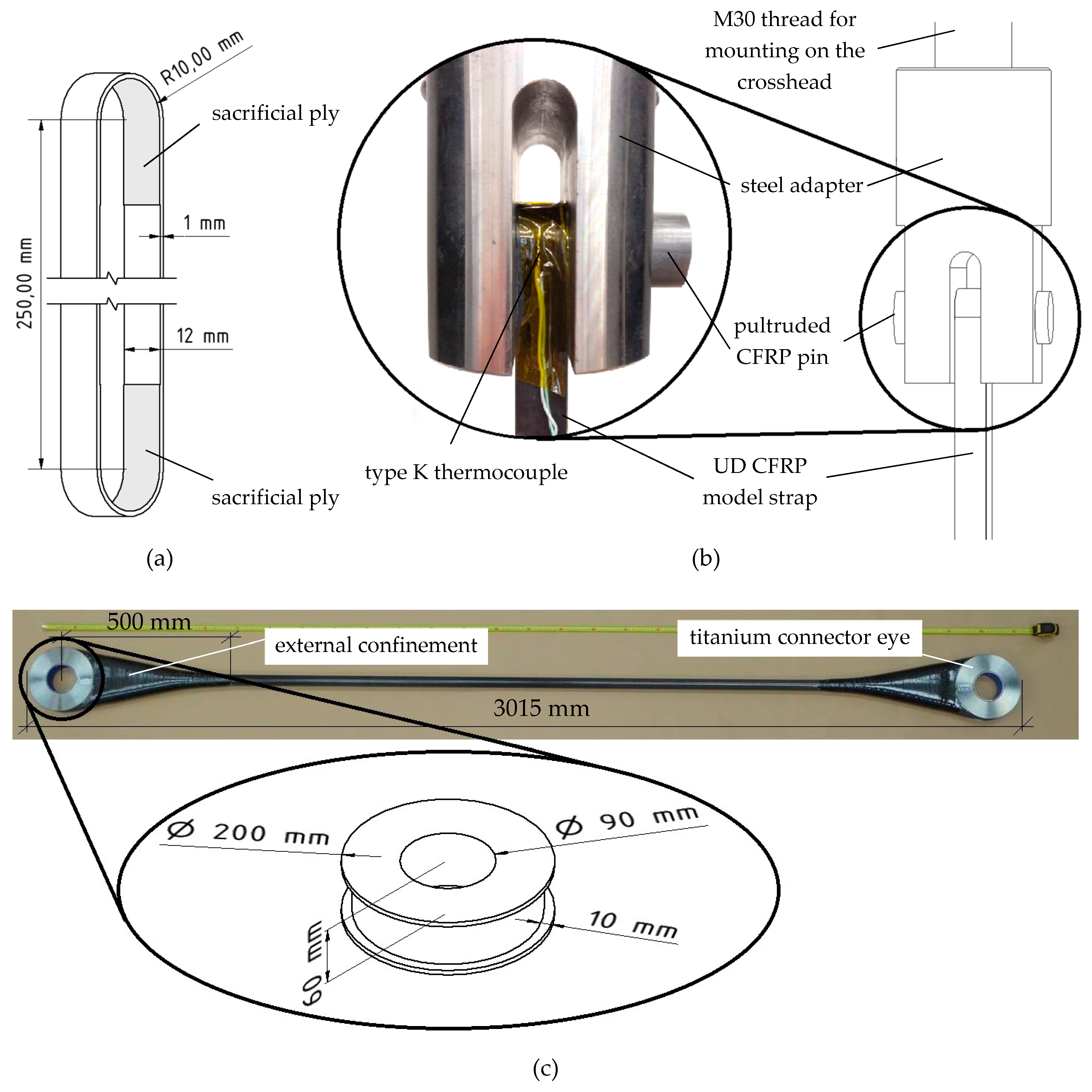
31], the fretting fatigue behaviour of laminated unidirectional CFRP straps as suspender models was investigated. The current paper studies the fretting fatigue behaviour of model straps (MS) comprising an additional sacrificial fibre ply between the innermost ply of the looped CFRP strap and the loading pin. Introducing a thin, low-stiffness/toughness fibre ply (e.g., glass: GFRP) between the innermost ply of the CFRP strap and the loading pin has been suggested by Schürmann [
32] as a way to reduce the stress concentrations at the curved part of the strap. In addition to this function, such a ply is considered in the current paper as sacrificial protection against fretting of the load-bearing 0° fibres of the CFRP strap. Because a glass fibre reinforcement significantly reduces the fretting wear resistance of the composite laminates [
22], a carbon fibre sacrificial ply was used instead. This comprised a woven fabric with fibres oriented in the ±45° direction, such that their influence on the axial stiffness of the strap is reduced, while still retaining significant resistance to fretting, as opposed to transversely oriented fibres [
21]. Another expected advantage of using a fabric made of carbon was that a possible fretting product might be graphite, which is known to be a good lubricant under the right conditions [
33].
Finally, in addition to the small-scale model straps, the behaviour of pristine full-scale laminated CFRP straps (FSS) in fretting fatigue tests without a sacrificial ply is also discussed.
3. Results
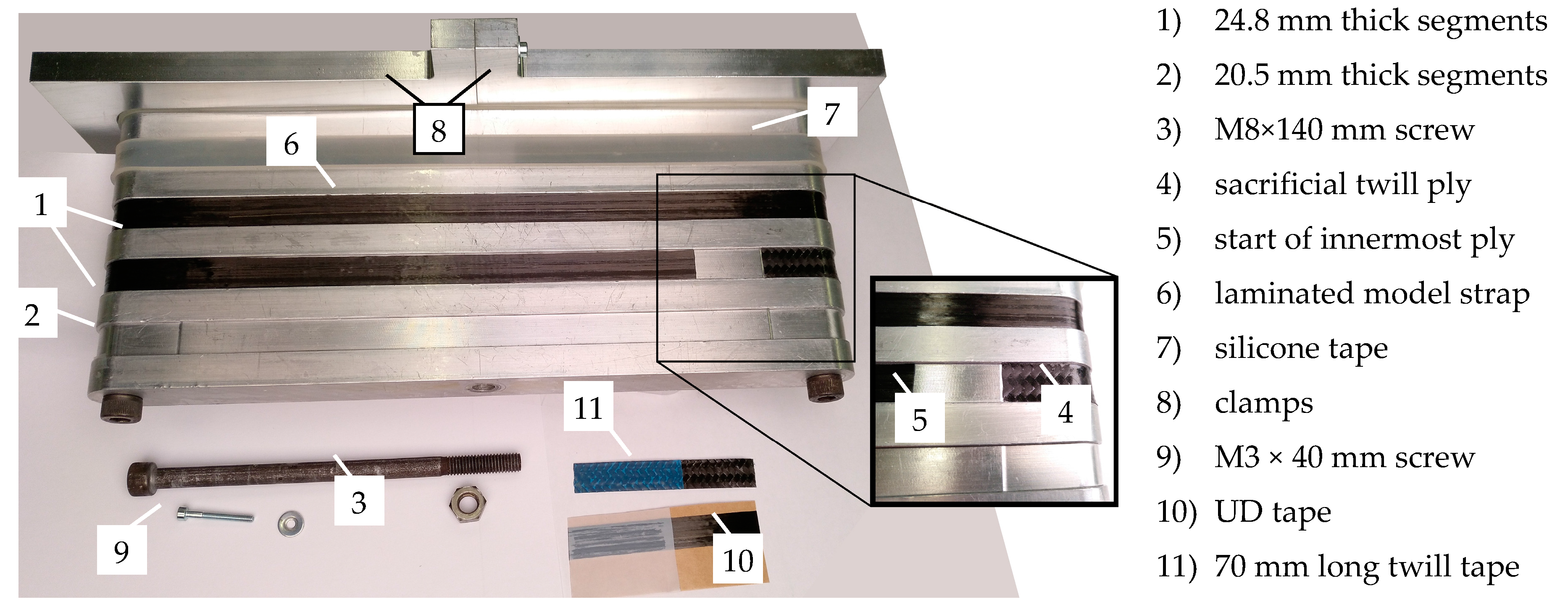
Thickness measurements of the model straps revealed a high scatter originating from their manufacturing process. A measured width variation of ±1 mm in the prepreg tape led to local discontinuities in the overlapping of the individual plies during lamination, resulting in extra plies if the tape was too wide or lacking plies wherever the tape was less than 12 mm wide. The chosen clamping system was not able to cope with these discontinuities and compact the laminate evenly, which resulted in a standard deviation of 10% of the laminate thickness. Hence, there were comparatively large local thickness variations in the model straps that made it difficult to determine the exact cross-sectional area of the straps and thus also the acting stresses in the model straps. As all model straps were manufactured from the same 12 mm wide tape and all full-scale straps were manufactured from the same 48 mm wide tape, for a better comparison of the two strap types, the apparent fibre stress in the straps (
σafs) is introduced and used throughout this study. It is calculated as follows:
with
F being the load (in (N)) and
Af the total cross-sectional area (in (mm
2)) of the unidirectional fibres in the shaft area in the respective strap. Due to the same amount of plies in each of the respective straps, this cross-sectional area was constant at a value of 16.96 mm
2 for the model straps and 531.56 mm
2 for the full-scale straps. The fibres of the sacrificial twill ply are excluded, since they are only applied locally and do not contribute to the load-bearing capacity of the strap in the shaft areas. With a Young’s modulus ratio of approximately 1:100 between the epoxy matrix and the IMS60 fibres and a
Vf of 64.8%, the contribution of the matrix to the load-bearing capacity in the strap shafts is less than 0.5% and is therefore neglected as well.
3.1. Quasi-Static Behaviour
In order to quantify the performance of the investigated straps under cyclic fretting fatigue loads, their pristine load-carrying capacity under quasi-static tensile loads had to be assessed first. Hence, five model straps and one full-scale strap were subjected to quasi-static tensile tests until failure.
Table 1 lists the strength and stiffness values obtained from these tests.
The similar straps of the previous study [
31] that did not have a sacrificial ply were characterised by an average tensile strength of 1,624 ± 121 MPa. This corresponds to an apparent fibre stress of 2368 ± 205 MPa at an average maximum tensile load of 40.2 ± 3.4 kN. The reported Young’s Modulus of the straps in [
31] of 175.8 ± 12.1 GPa corresponds to an apparent Young’s Modulus of 259.9 ± 15.2 GPa. Comparing the results in
Table 1 with [
31], it can be said that the model straps with an additional, sacrificial ply in the curved areas show marginally higher strength (+4.9%) and stiffness (+6.8%) values at marginally higher coefficients of variation (CoV: ratio of standard deviation to the mean value) compared to model straps without a sacrificial ply. The full-scale strap reached a significantly higher apparent ultimate tensile stress (
σafs,max) than that of the model straps (+36.9%).
3.2. Fretting Fatigue
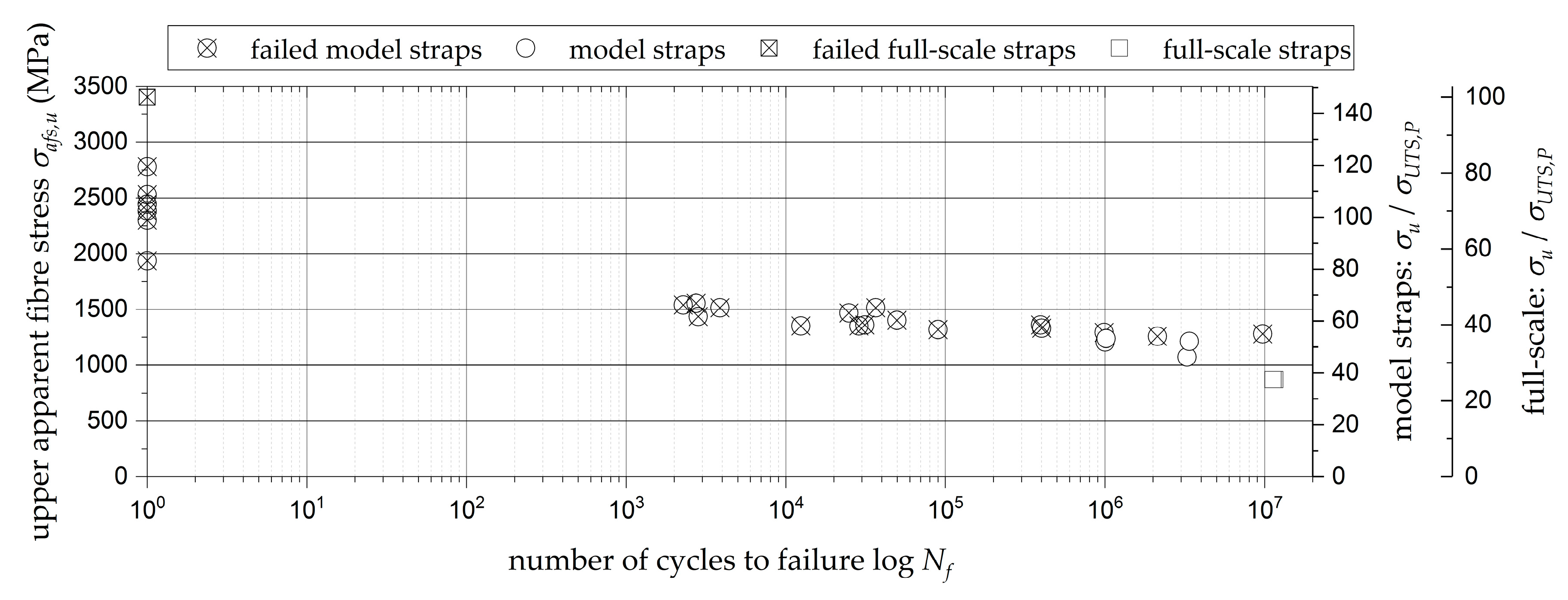
Figure 3 shows the S-N curve obtained from the quasi-static and fretting fatigue testing of 25 pin-loaded model straps with a sacrificial ply (circular markers). As the pristine model straps with a sacrificial ply performed equal to the pristine straps tested in [
31] under quasi-static loading, it was expected that they would perform even better under cyclic fretting fatigue loading. Therefore, the first fatigue tests were performed at an upper load level (
Fu) of 60% of the quasi-static tensile strength of the model straps. At this load level, the straps already failed prematurely at less than 10
4 load cycles. In order to determine the fatigue limit load of the model straps with a sacrificial ply,
Fu was continuously reduced. At load levels below 55% of the pristine tensile strength of the model straps, the first straps endured more than 1 Million load cycles. However, out of those six straps, only four did so without failure. Two of the straps tested for
N >10
6, at 52.5% and 53.5% of the pristine
Fmax, failed after 2.1 and 9.7 million load cycles, respectively.
Although the full-scale straps were tested at a different frequency and load ratio (
f = 4.2 Hz,
R = 0.2, 0.42) than the model straps, the results from the full-scale strap tests (square markers) are also included in
Figure 3. Both full-scale straps tested at 25.5% of the pristine full-scale strap tensile strength endured more than 11 × 10
6 load cycles without failure (see also
Table 2).
3.3. Residual Mechanical Properties
The residual mechanical properties of the straps that did not fail under cyclic fretting fatigue loading were assessed in quasi-static tensile tests as described in
Section 2.3.
Table 3 lists the results of these tests.
The comparison of the residual mechanical properties to the mechanical properties of pristine straps (
Table 1) shows that the ultimate tensile strength of the model straps remained almost unchanged. At the same time, their apparent fibre parallel stiffness decreased by 10.4%. This might be attributed to damages observed in the fatigued laminate, i.e., delaminations and fibre-parallel matrix cracks that increase the longitudinal compliance of the laminate, but only marginally affect its ultimate tensile strength. Similar results have also been presented in [
31]. The strains on the full-scale straps could not be measured, but the test revealed a significant decrease in ultimate tensile strength of the full-scale straps after a cyclic fretting fatigue loading of 25%. This much stronger strength decrease is in good agreement with the reported stronger reduction in fatigue life when using a harder pin material in contact with a unidirectional CFRP ply loaded in the fibre direction [
29].
3.4. Damage Modes
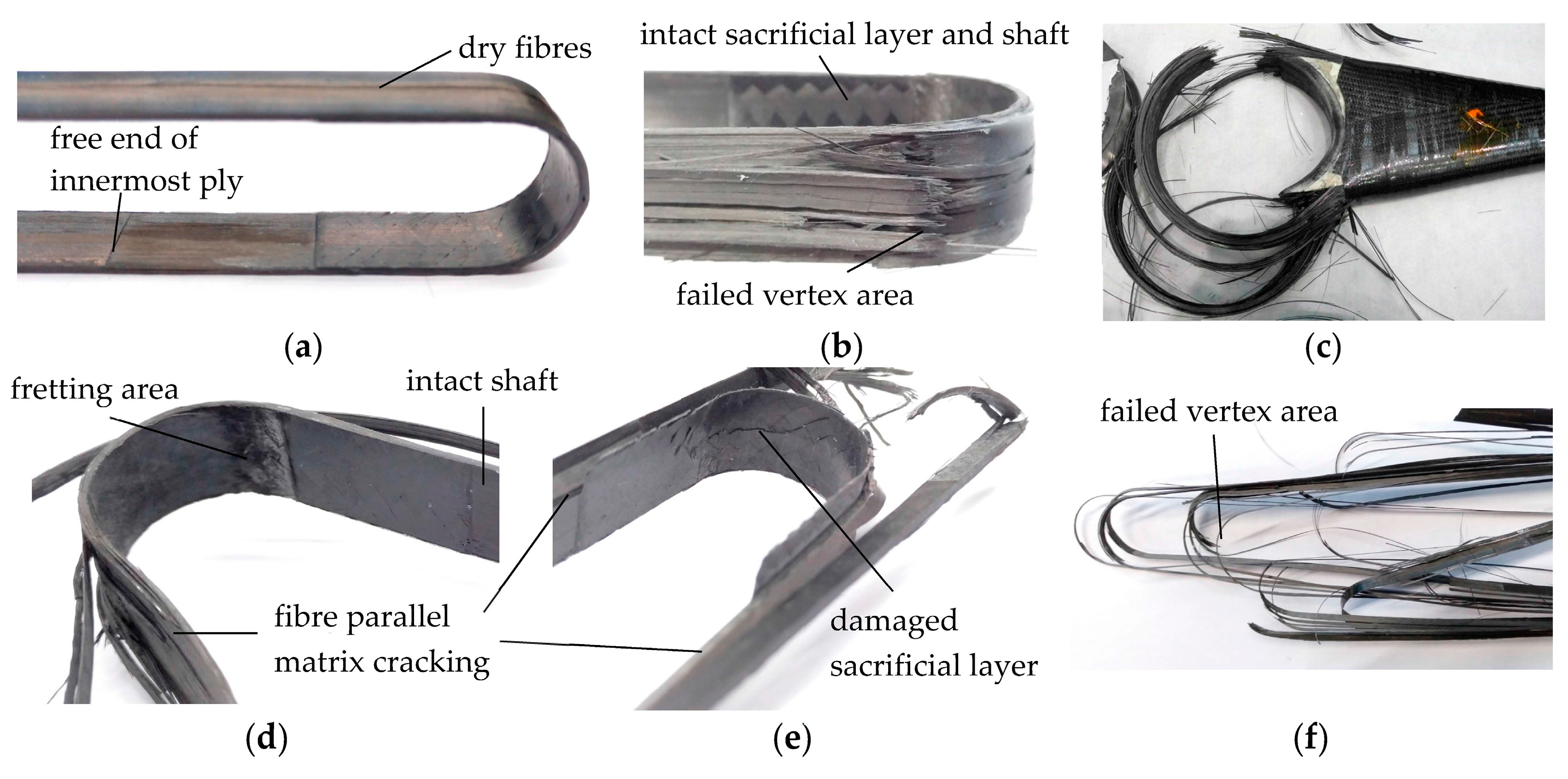
All model straps included in this study initially failed in their vertex areas (see
Figure 4b) with subsequent fibre bursting in the shaft or crown area. The first visible damages of the model straps were delamination of the inner and outermost plies in the shaft with the overlapping plies. Delaminations initiated at the free ends of the overlaps and progressed towards the vertex areas where they stopped. The same fibre-parallel longitudinal cracking as described in [
31] was observed on the model straps with a sacrificial twill ply during the fatigue tests prior to failure. After the premature failure in the vertex area of the straps due to the cyclic fretting fatigue loading, different types of secondary failures were observed.
Figure 4d shows a failed strap with the inner part of the curved section and one shaft (right) being still mostly intact, whilst the outermost plies and the opposite shaft (left) are severely damaged.
Figure 4e shows a strap where both shafts and the complete curved section, including the sacrificial ply, were severely damaged.
Figure 4b,d,e are representative images of all observed premature failures during cyclic fretting fatigue loading of the model straps. However, there appears to be no correlation between the different types of secondary failure and the (upper) load level that the straps were exposed to during testing.
Figure 4f shows a model strap after failure due to a residual ultimate tensile strength test. All model straps tested for their pristine or residual ultimate tensile strength failed primarily in the vertex area with a more pronounced secondary fibre bursting in the shafts compared to the prematurely failed fatigue-tested straps. In case of the model straps tested for their residual ultimate tensile strength, this fibre bursting in the shaft resulted in more and smaller bristles due to the previous fibre-parallel damaging of the laminate.
The failure of full-scale strap FSS C occurred similar to the model straps, with initial failure in the vertex area (see
Figure 4c) followed by fibre bursting in the shaft. The fatigue-tested full-scale straps showed no signs of fibre bursting in the shaft but significant fibre-parallel matrix cracking.
3.5. Fretting Behaviour of Contacting Surfaces
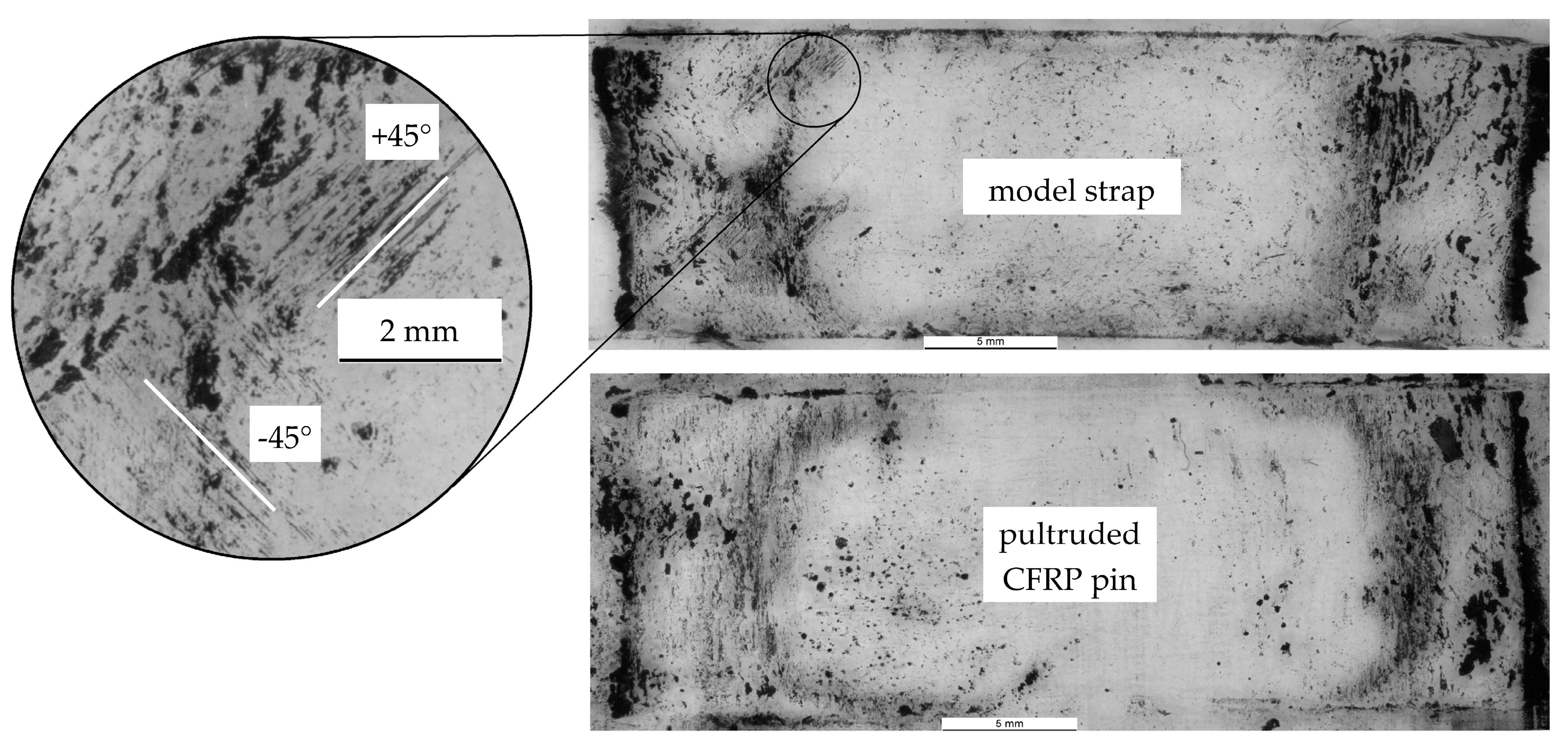
The fretting behaviour of the contacting surfaces was investigated differently for the two types of straps. By placing a transparent adhesive tape on the model strap and CFRP pin surfaces just after testing, the fretting products of these tests could be investigated. The tapes were placed on microscope slides and were examined under an optical microscope (ZEISS Stemi SV 11 in reflected-light mode).
Figure 5 shows two representative pictures of the fretting products on a strap and a pin. The fretting products on the pin look similar to those described in [
31], with mostly short, broken fibres and resin particles still attached to them. The fretting products on the strap are mainly small carbon particles (see [
31]). However, the presence of the contacting twill ply can be clearly seen from the fibres oriented in ±45° (relative to the unidirectional fibres along the strap axis). However, these ±45° fibres were only visible on one of the two fretting areas.
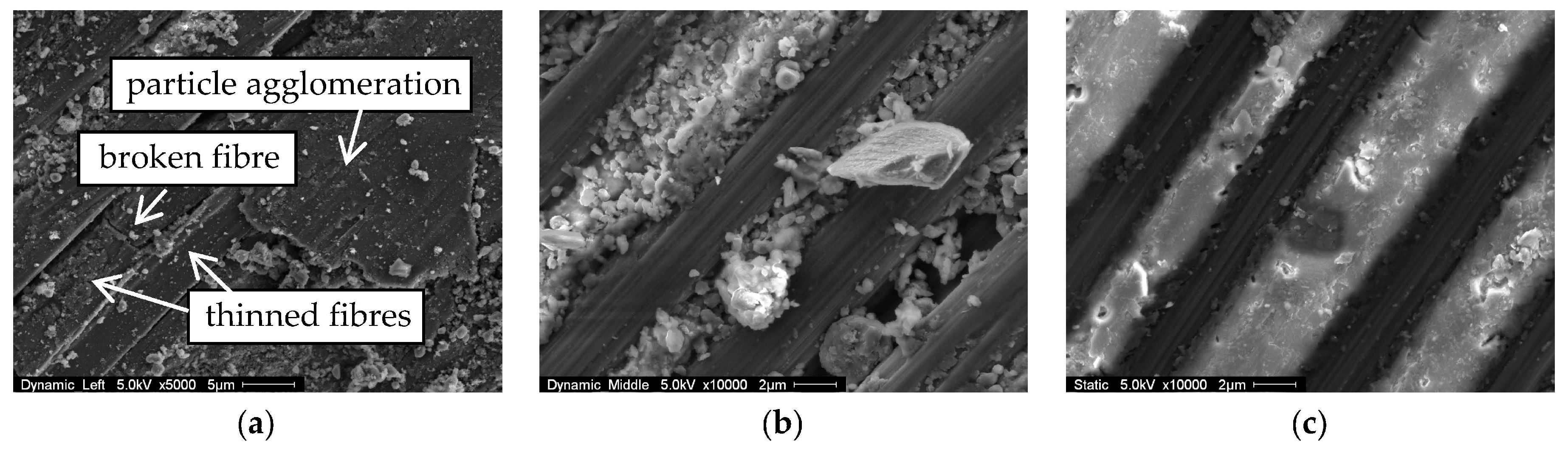
The contacting surfaces of the full-scale straps were investigated under a scanning electron microscope (SEM, FEI ESEM XL30).
Figure 6 shows three pictures of typical surface conditions after testing.
Figure 6c shows the surface of FSS C in contact with the titanium connector eye in the vertex area. As the strap was not exposed to fatigue testing, the fibres (dark) are still well-embedded in the intact matrix (light) and show no signs of fibre thinning. In the regions close to the top (crown) where the relative movement between strap and connector eye is relatively small, the surface of the fatigue tested FSS A was similar. Further away from the top (crown) of the strap, see
Figure 6b, the fibres are still intact, but the matrix suffered from the small relative movement between the strap and the connector eye. This matrix deterioration is even more pronounced in the vertex areas of fatigue tested straps,
Figure 6a, where the fibres are not visibly embedded in the matrix anymore. The fibre-parallel fretting also caused fibre thinning (
Figure 6a, left), and the fretting products agglomerated and covered the fibres (
Figure 6a, right). These particle agglomerations consist of compressed fretting products with particle diameters of 30–100 nm.
3.6. Temperature
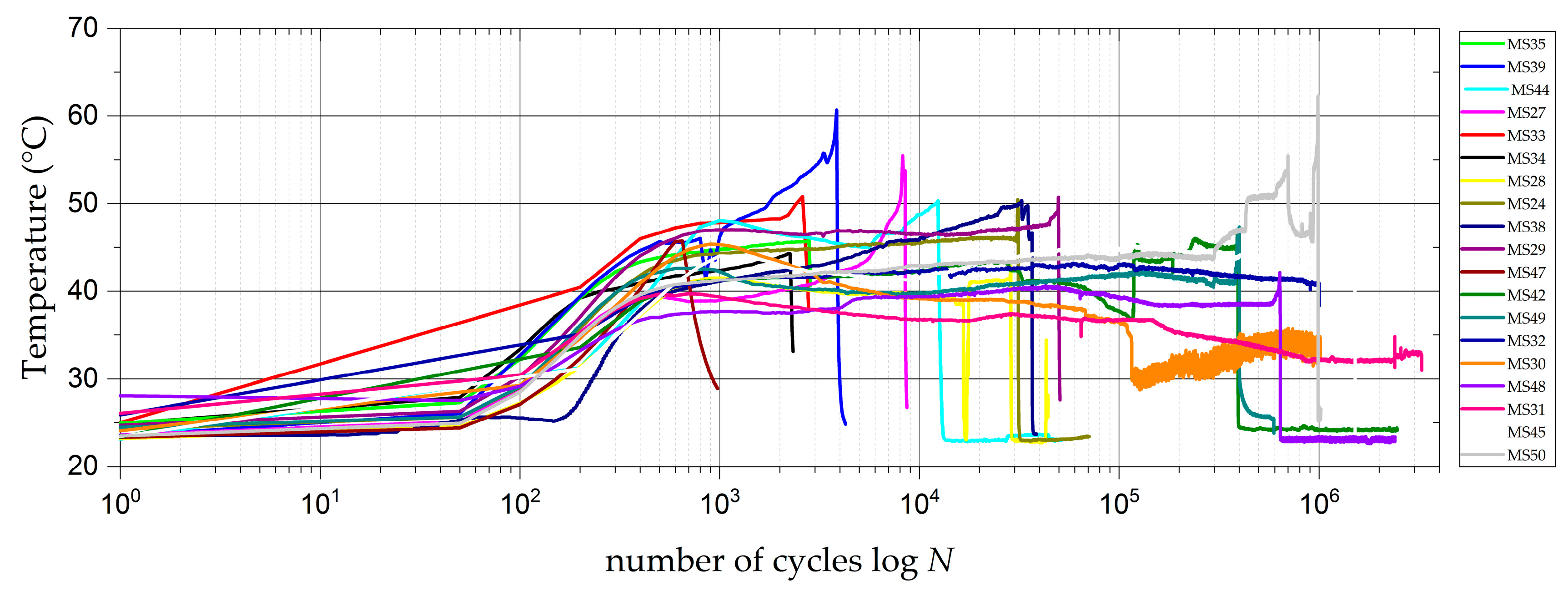
Due to the high testing frequencies, the temperature on the outside of the straps was monitored during all fatigue tests. The thermocouples on the outside of the model straps measured a significant initial temperature increase, which reached a peak value within the first 5000 load cycles. In contrast to straps tested without a sacrificial ply [
31], the temperature does not drop off significantly after this peak, but levels out at an only a slightly lower temperature (see
Figure 7). The temperatures increase again once final failure of the straps is initialised. The maximum measured initial temperature peaks on the outside of the model straps were all below 50 °C. With a reported glass transition temperature (
Tg) of the epoxy matrix system of 140 °C [
35], these temperatures never endangered the structural integrity of the straps.
The temperature measurements on the outside of the full-scale strap FSS A revealed a maximum temperature of 80 °C after 2 × 10⁴ load cycles. As the temperature did not decrease within the subsequent 5000 load cycles and with a laminate thickness of 10 mm, it had to be assumed that the temperature inside the laminate was much higher. Consequently, the test was paused and Fu was reduced from 575 kN (σafs,u = 1081 MPa) to 462 kN (σafs,u = 869 MPa) to ensure the laminate temperature did not exceed Tg anywhere in the laminate. After these adjustments, the temperature did not exceed 50 °C, which was also the maximum temperature measured on FSS B during the cyclic fretting fatigue loading.
4. Discussion
The laminated unidirectional CFRP tension members investigated in this study were shown to be a good alternative to well-established steel tension members in terms of their fretting fatigue behaviour [
44,
45,
46]. The introduction of an additional sacrificial ply protecting the load-carrying fibres during the cyclic fretting fatigue tests did not result in the expected increase in durability of the investigated model straps as the sacrificial plies did not influence the failure mode. The failure was still initiated and determined by the fibre-parallel stress concentrations in the vertex areas of the straps as described in [
31]. One strap failed only after 9.7 × 10
6 load cycles, which is far above 3 ×10
6 load cycles. This has previously been reported to correspond to the fretting fatigue endurance limit of comparable straps [
31]. However, complications with proper compaction of the model strap laminate during curing resulted in strongly varying thicknesses of the straps along their width. Although the laminate quality could be shown to be satisfying in general (
Vf = 64% and a void content of 1%), such surface irregularities lead to stress concentrations and can act as stress inducers that have a strong influence on the fatigue behaviour of CFRP laminates [
47] and should hence be eliminated in future studies.
The ultimate tensile strength tests of pristine straps revealed significantly higher failure stresses in the full-scale straps. A better laminate quality due to the robotic manufacturing of the straps with a tape-laying machine, the different pin geometry, and the lateral confinement of the full-scale strap, which reduced unfavorable stress concentrations in the transition zone, might, however, explain these results. The residual ultimate tensile strength tests of both the model and full-scale straps resulted in similar apparent failure stresses of both strap types at around 2500 MPa. This in turn means that the full-scale strap strength was reduced by 25% due to the fretting fatigue testing, whilst the model strap strength remained almost the same. The strong reduction of the full-scale strap strength can be tentatively attributed to the harder pin material and the larger contacting area (see [
29]) acting on the laminate. The average residual failure stresses of the model straps on the other hand are almost the same (100.3%) as the pristine tensile strength of model straps. This supports the findings in [
31], where the residual strength of the straps corresponded to 99.7% of the pristine tensile strength.
The temperature measurements on the model straps showed no perturbing temperature increase due to the cyclic fretting fatigue loading. The different geometry, a thicker laminate, and different material partners in combination with a larger contacting area led to a strong temperature increase on the full-scale strap surface that was too high to disregard, and adequate measures had to be taken to inhibit the high temperatures.
The presented results are part of a pioneering study on the fretting fatigue of fibre-dominated tensile elements. The model straps used throughout this study had a similar ratio of outer to inner radius of curvature as the full-scale straps. Nevertheless, the different quasi-static strengths and the different fretting behaviour (e.g., with respect to temperature development and residual properties) of the two strap types have shown that further studies are necessary. Such studies should focus on size effects, e.g., by upscaling the model strap without lateral confinement or variation of the radius of curvature ratio, as well as on the influence of the connector eye material and geometry on the fretting fatigue behaviour. Furthermore, the fact that the ±45° fibres were only observed in one fretting area should be investigated as it might be a result of an uneven loading that could result in an additional reduction of the fatigue resistance of the straps. Future research should also contemplate the behaviour of pin-loaded CFRP straps exposed to harsh environmental conditions, such as salt water, humidity, and high temperatures.


