Interlaminar Toughening of Epoxy Carbon Fiber Reinforced Laminates: Soluble Versus Non-Soluble Veils

 ,
, 
Abstract
: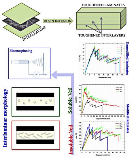
1. Introduction
2. Experiments
2.1. Materials and Methods
2.1.1. Materials
2.1.2. Preparation of the Soluble Electro Spun Veils
2.1.3. Composites Manufacturing
2.2. Characterization
2.2.1. Dynamic Mechanical Analysis (DMA) of the Cured Composites
2.2.2. Scanning Electron Microscopy (SEM)
2.2.3. Double Cantilever Bending (DCB) Testing
3. Results and discussion
3.1. Veil Morphology
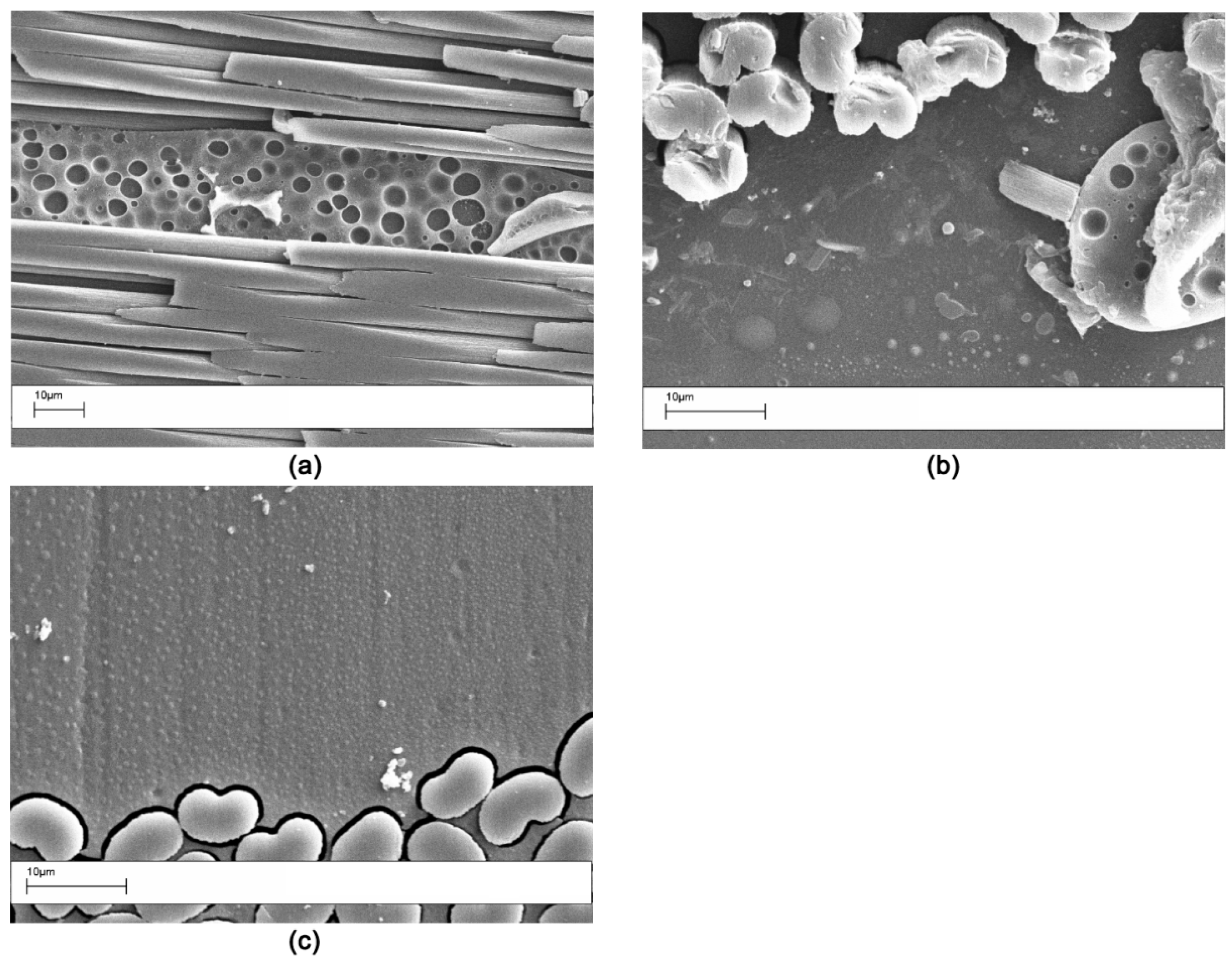
3.2. Interlaminar Morphology for the Modified Composites
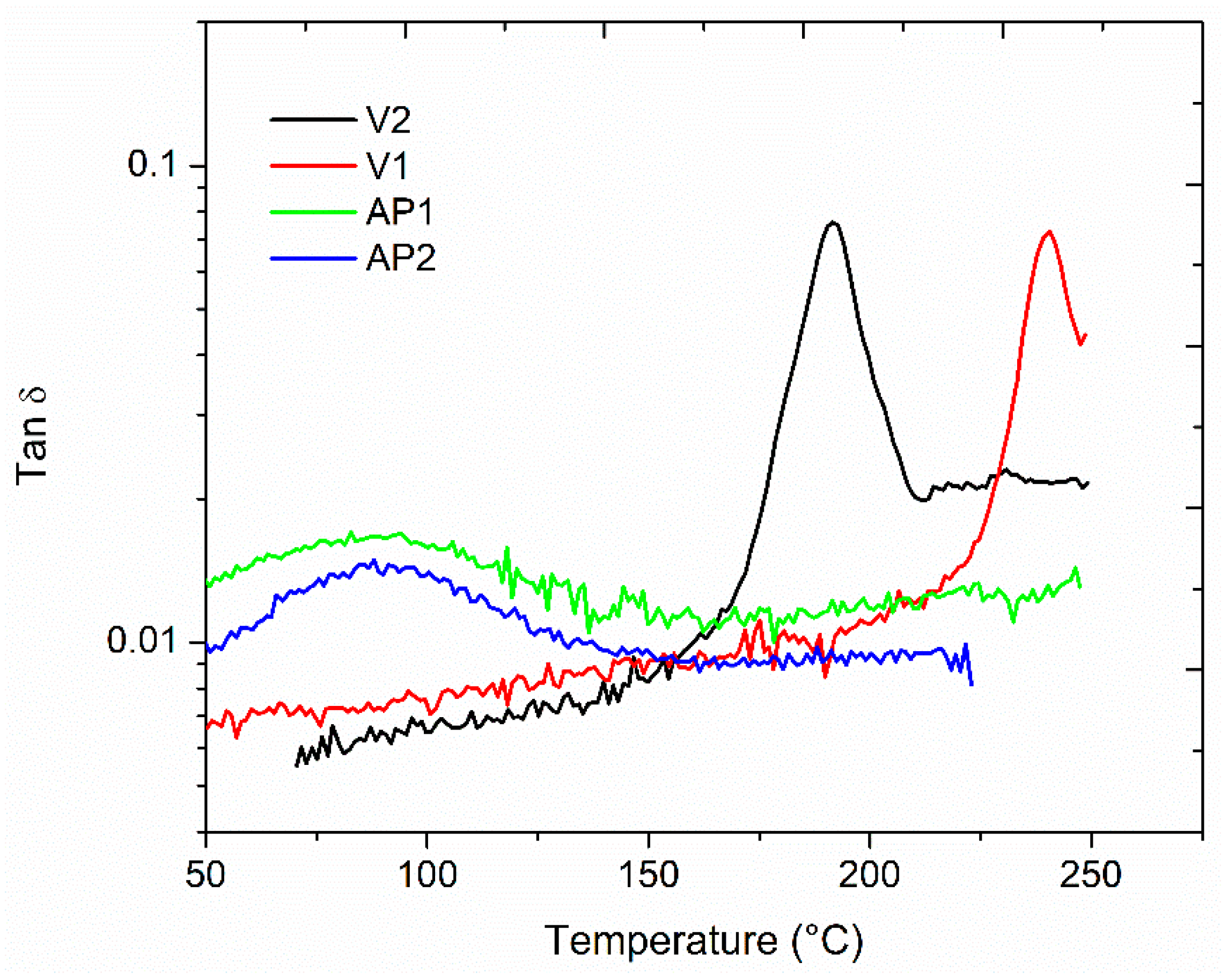
3.3. DMA Analysis for the Modified Composites
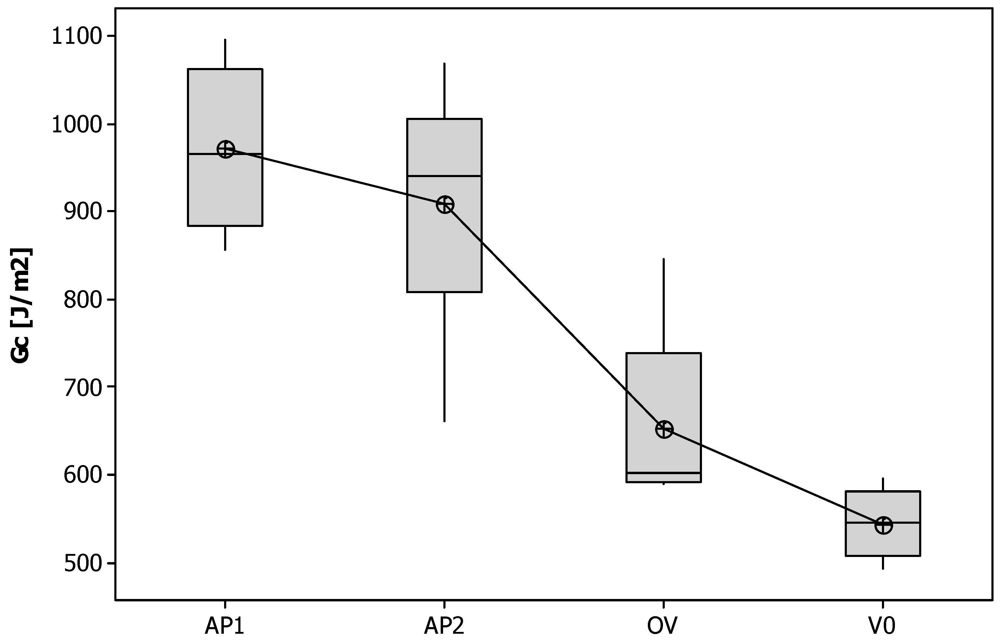
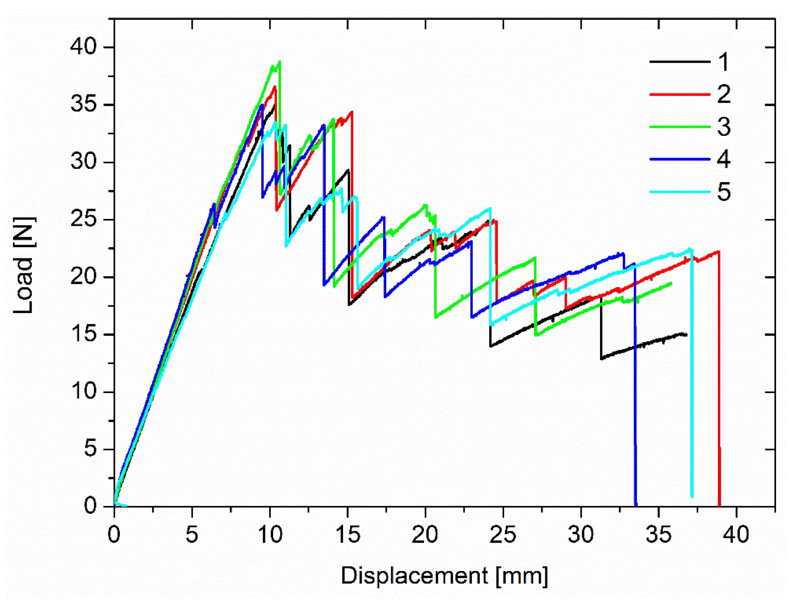
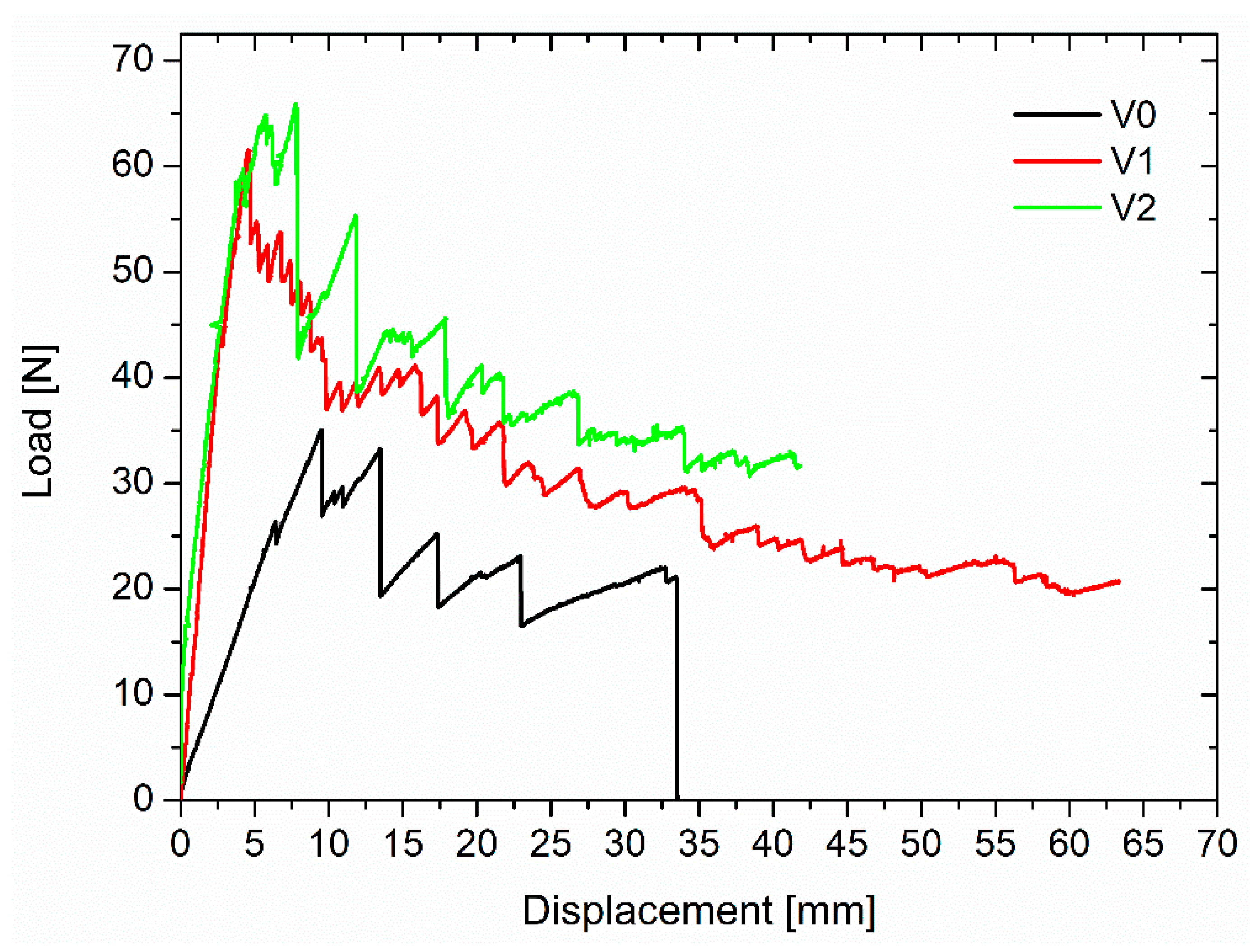
3.4. DCB Properties of the Laminates
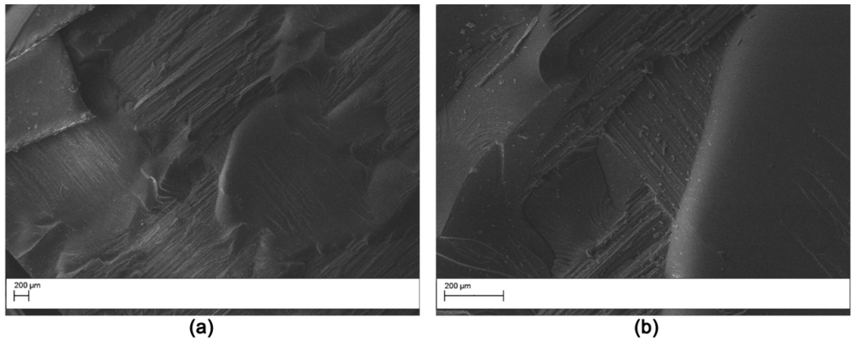
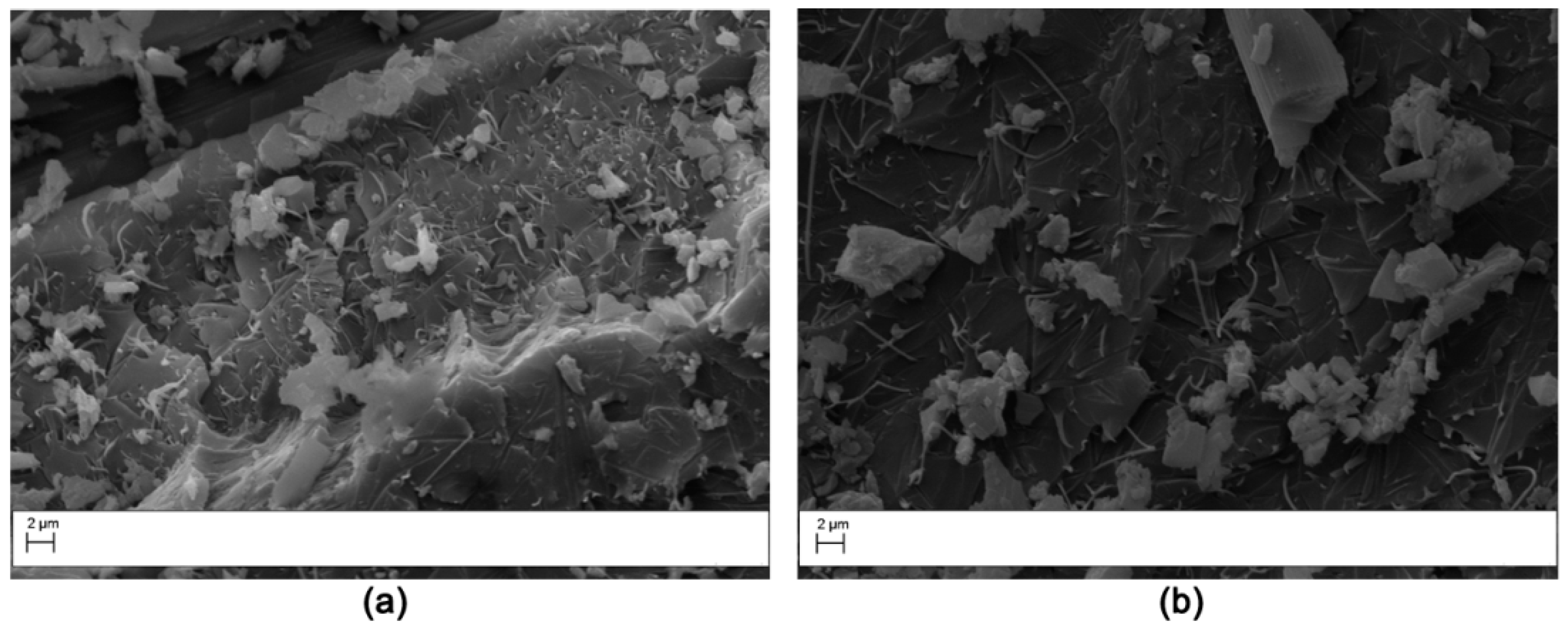
3.5. Fracture Surface after Mode I Testing
4. Conclusions
Author Contributions
Funding
Acknowledgments
Conflicts of Interest
References
- Cicala, G. Comparison of Epoxy/Rubber Blends with Other Toughening Strategies: Thermoplastic and Hyperbranched Modifiers. In Micro and Nanostructured Epoxy/Rubber Blends; Wiley-VCH Verlag GmbH & Co.: New York, NY, USA, 2014. [Google Scholar] [CrossRef]
- Carfagna, C.; Ambrogi, V.; Cicala, G.; Pollicino, A.; Recca, A.; Costa, G. Reactive microspheres as active fillers for epoxy resins. J. Appl. Polym. Sci. 2004, 93. [Google Scholar] [CrossRef]
- Akangah, P.; Lingaiah, S.; Shivakumar, K. Effect of Nylon-66 nano-fiber interleaving on impact damage resistance of epoxy/carbon fiber composite laminates. Compos. Struct. 2010, 92, 1432–1439. [Google Scholar] [CrossRef]
- Palazzetti, R.; Zucchelli, A.; Gualandi, C.; Focarete, M.L.; Donati, L.; Minak, G. Influence of electrospun Nylon 6,6 nanofibrous mats on the interlaminar properties of Gr-epoxy composite laminates. Compos. Struct. 2012, 94, 571–579. [Google Scholar] [CrossRef]
- Beckermann, G.W.; Pickering, K.L. Mode I and Mode II interlaminar fracture toughness of composite laminates interleaved with electrospun nanofibre veils. Compos. Part A Appl. Sci. Manuf. 2015, 72, 11–21. [Google Scholar] [CrossRef]
- Li, G.; Huang, Z.; Xin, C.; Li, P.; Jia, X.; Wang, B.; He, Y.; Ryu, S.; Yang, X. Morphology evolution of polysulfone nanofibrous membranes toughened epoxy resin during reaction-induced phase separation. Mater. Chem. Phys. 2009, 118, 398–404. [Google Scholar] [CrossRef]
- Cicala, G.; Latteri, A.; Mannino, S.; Ognibene, G.; Blanco, I. Influence of Soluble Electrospun Co-Polyethersulfone Veils on Dynamic Mechanical and Morphological Properties of Epoxy Composites: Effect of Polymer Molar Mass. Adv. Polym. Technol. 2016. [Google Scholar] [CrossRef]
- Magniez, K.; De Lavigne, C.; Fox, B.L. The effects of molecular weight and polymorphism on the fracture and thermo-mechanical properties of a carbon-fibre composite modified by electrospun poly (vinylidene fluoride) membranes. Polymer 2010, 51, 2585–2596. [Google Scholar] [CrossRef]
- Magniez, K.; Chaffraix, T.; Fox, B. Toughening of a Carbon-Fibre Composite Using Electrospun Poly(Hydroxyether of Bisphenol A) Nanofibrous Membranes Through Inverse Phase Separation and Inter-Domain Etherification. Materials 2011, 4, 1967–1984. [Google Scholar] [CrossRef] [Green Version]
- Li, G.; Jia, X.; Huang, Z.; Zhu, B.; Li, P.; Yang, X.; Dai, W. Prescribed morphology and interface correlation of MWNTs-EP/PSF hybrid nanofibers reinforced and toughened epoxy matrix. Mater. Chem. Phys. 2012, 134, 958–965. [Google Scholar] [CrossRef]
- Cicala, G.; Latteri, A.; Mannino, S.; Cozzo, G.; Ognibene, G.; Recca, A. Thermoplastic veils as advanced modifiers for multifunctional fiber reinforced composites. AIP Conf. Proc. 2014, 1599, 46–49. [Google Scholar] [CrossRef]
- Lionetto, F.; Calò, E.; Di Benedetto, F.; Pisignano, D.; Maffezzoli, A. A methodology to orient carbon nanotubes in a thermosetting matrix. Compos. Sci. Technol. 2014, 96, 47–55. [Google Scholar] [CrossRef]
- Hamer, S.; Leibovich, H.; Green, A.; Avrahami, R.; Zussman, E.; Siegmann, A.; Sherman, D. Mode I and Mode II fracture energy of MWCNT reinforced nanofibrilmats interleaved carbon/epoxy laminates. Compos. Sci. Technol. 2014, 90, 48–56. [Google Scholar] [CrossRef]
- Cicala, G.; Blanco, I.; Latteri, A.; Ognibene, G.; Bottino, F.A.; Fragalà, M.E. PES/POSS soluble veils as advanced modifiers for multifunctional fiber reinforced composites. Polymers 2017, 9, 281. [Google Scholar] [CrossRef] [PubMed]
- Beckermann, G.W.; Hosie, I.; Collins-Gargan, R.; Pickering, K.L. Nanofibre interleaving veils for the improvement of carbon fibre composites. In Proceedings of the CAMX 2018—Composites and Advanced Materials Expo, Dallas, TX, USA, 15–18 October 2018. [Google Scholar]
- Cicala, G.; Mannino, S.; Latteri, A.; Ognibene, G.; Saccullo, G. Effects of mixing di- and tri-functional epoxy monomers on epoxy/thermoplastic blends. Adv. Polym. Technol. 2017. [Google Scholar] [CrossRef]
- Blanco, I.; Cicala, G.; Costa, M.; Recca, A. Development of an epoxy system characterized by low water absorption and high thermomechanical performances. J. Appl. Polym. Sci. 2006, 100. [Google Scholar] [CrossRef]
- Girard-Reydet, E.; Vicard, V.; Pascault, J.P.; Sautereau, H. Polyetherimide-modified epoxy networks: Influence of cure conditions on morphology and mechanical properties. J. Appl. Polym. Sci. 1997, 65, 2433–2445. [Google Scholar] [CrossRef]
- Mahlin, D.; Wood, J.; Hawkins, N.; Mahey, J.; Royall, P.G. A novel powder sample holder for the determination of glass transition temperatures by DMA. Int. J. Pharm. 2009, 371, 120–125. [Google Scholar] [CrossRef]
- Cicala, G.; Mamo, A.; Recca, G.; Restuccia, C.L. Synthesis and thermal characterization of some novel ABA block copolymers. Macromol. Mater. Eng. 2007, 292. [Google Scholar] [CrossRef]
- Carlier, V.; Sclavons, M.; Legras, R. Supported dynamic mechanical thermal analysis: An easy, powerful and very sensitive technique to assess thermal properties of polymer, coating and even nanocoating. Polymer 2001, 42, 5327–5335. [Google Scholar] [CrossRef]
- Cicala, G.; Recca, G. Studies on epoxy blends modified with a hyperbranched polyester. Polym. Eng. Sci. 2008, 48. [Google Scholar] [CrossRef]
- Beckermann, G.W. Nanofiber interleaving veils for improving the performance of composite laminates. Reinf. Plast. 2017, 61, 289–293. [Google Scholar] [CrossRef]
- Kuwata, M.; Hogg, P.J. Interlaminar toughness of interleaved CFRP using non-woven veils: Part 2. Mode-II testing. Compos. Part A Appl. Sci. Manuf. 2011, 42, 1560–1570. [Google Scholar] [CrossRef]
- Yee, A.F.; Du, J.; Thouless, M.D. Toughening of Epoxies. In Polymer Blends; Paul, D.R., Bucknall, C.B., Eds.; John Wiley & Sons: Hoboken, NJ, USA, 2000; Volume 2, ISBN 0-471-35280-2. [Google Scholar]


| Sample Code | Interlaminar Modifier |
|---|---|
| Base | None |
| V1 | Virantage 10,200 |
| V2 | Virantage 30,500 |
| AP1 | AP1500 |
| AP2 | AP4500 |
| OV | Optiveil |
| Veil | Diameter Avg [nm] | Areal Weight [g/m2] |
|---|---|---|
| V1 | 873 | 1.50 |
| V2 | 450 | 4.50 |
| AP1 | 165 | 1.68 |
| AP2 | 348 | 2.48 |
| OV | 7864 | 11.72 |
© 2019 by the authors. Licensee MDPI, Basel, Switzerland. This article is an open access article distributed under the terms and conditions of the Creative Commons Attribution (CC BY) license (http://creativecommons.org/licenses/by/4.0/).
Share and Cite
Ognibene, G.; Latteri, A.; Mannino, S.; Saitta, L.; Recca, G.; Scarpa, F.; Cicala, G. Interlaminar Toughening of Epoxy Carbon Fiber Reinforced Laminates: Soluble Versus Non-Soluble Veils. Polymers 2019, 11, 1029. https://doi.org/10.3390/polym11061029
Ognibene G, Latteri A, Mannino S, Saitta L, Recca G, Scarpa F, Cicala G. Interlaminar Toughening of Epoxy Carbon Fiber Reinforced Laminates: Soluble Versus Non-Soluble Veils. Polymers. 2019; 11(6):1029. https://doi.org/10.3390/polym11061029
Chicago/Turabian StyleOgnibene, Giulia, Alberta Latteri, Salvatore Mannino, Lorena Saitta, Giuseppe Recca, Fabrizio Scarpa, and Gianluca Cicala. 2019. "Interlaminar Toughening of Epoxy Carbon Fiber Reinforced Laminates: Soluble Versus Non-Soluble Veils" Polymers 11, no. 6: 1029. https://doi.org/10.3390/polym11061029