
Control of Meniscus Formation Using an Electrohydrodynamics Module in Roll-to-Roll Systems for the Stable Coating of Functional Layers
 , ,
, , 
Abstract
:1. Introduction
2. Theoretical Background
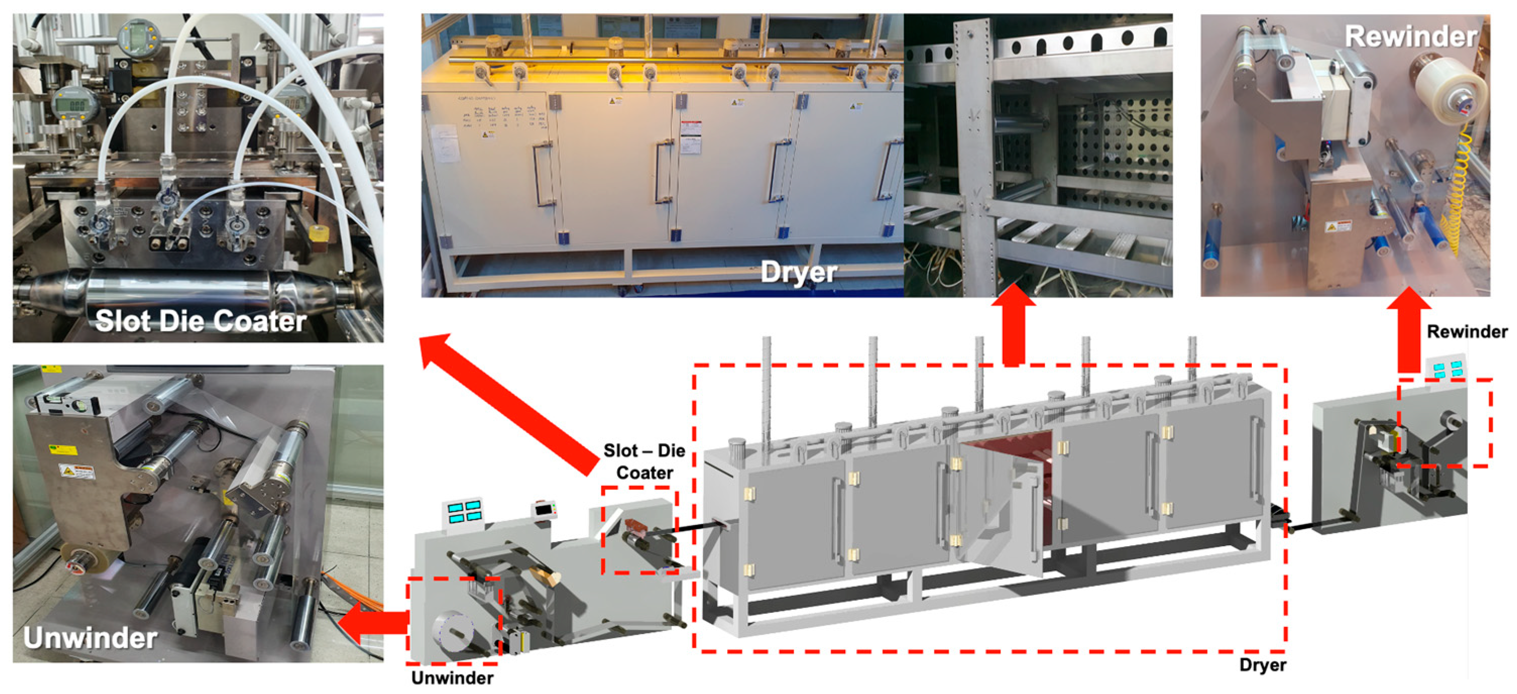
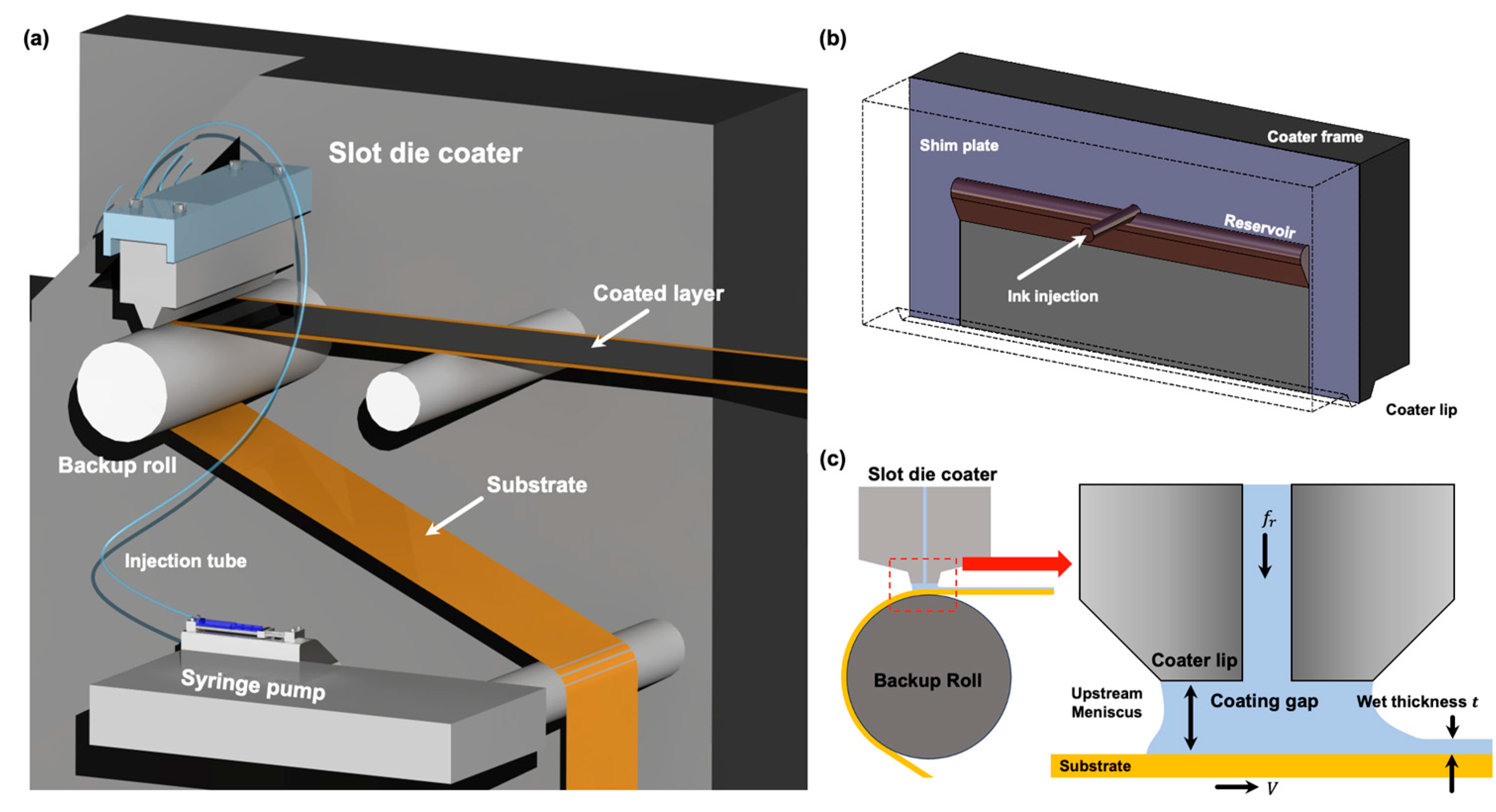
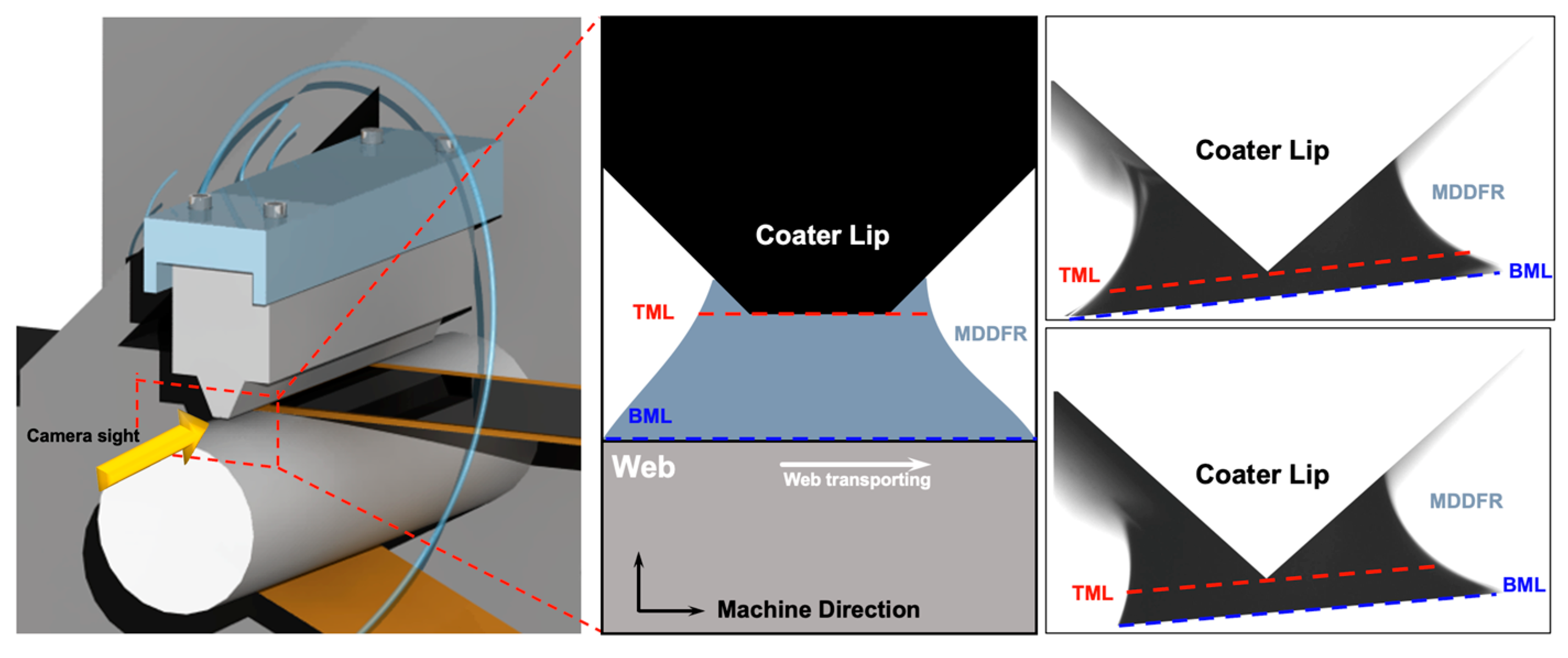
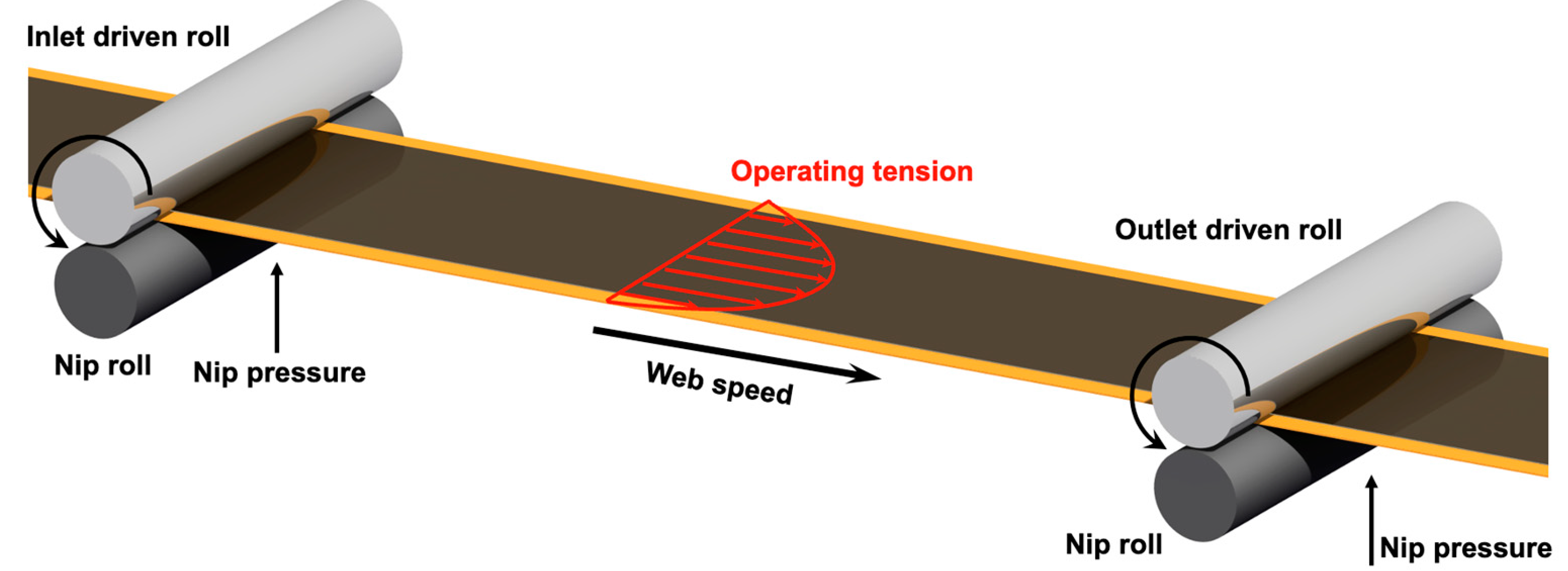
2.1. Roll-to-Roll Slot-Die Coating Systems
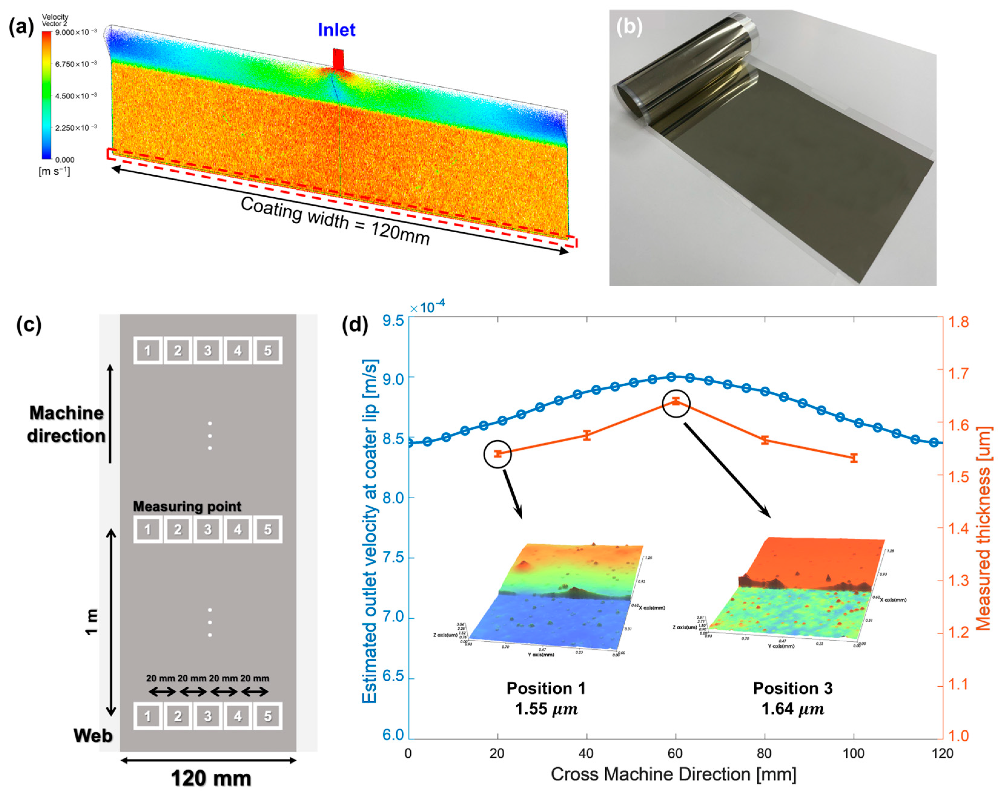
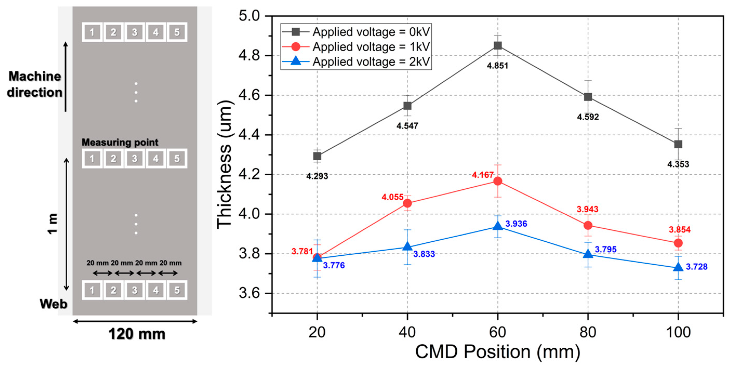
2.2. Coated Layer Thickness Uniformity
2.3. Instability at High Operating Speeds
3. Methodology
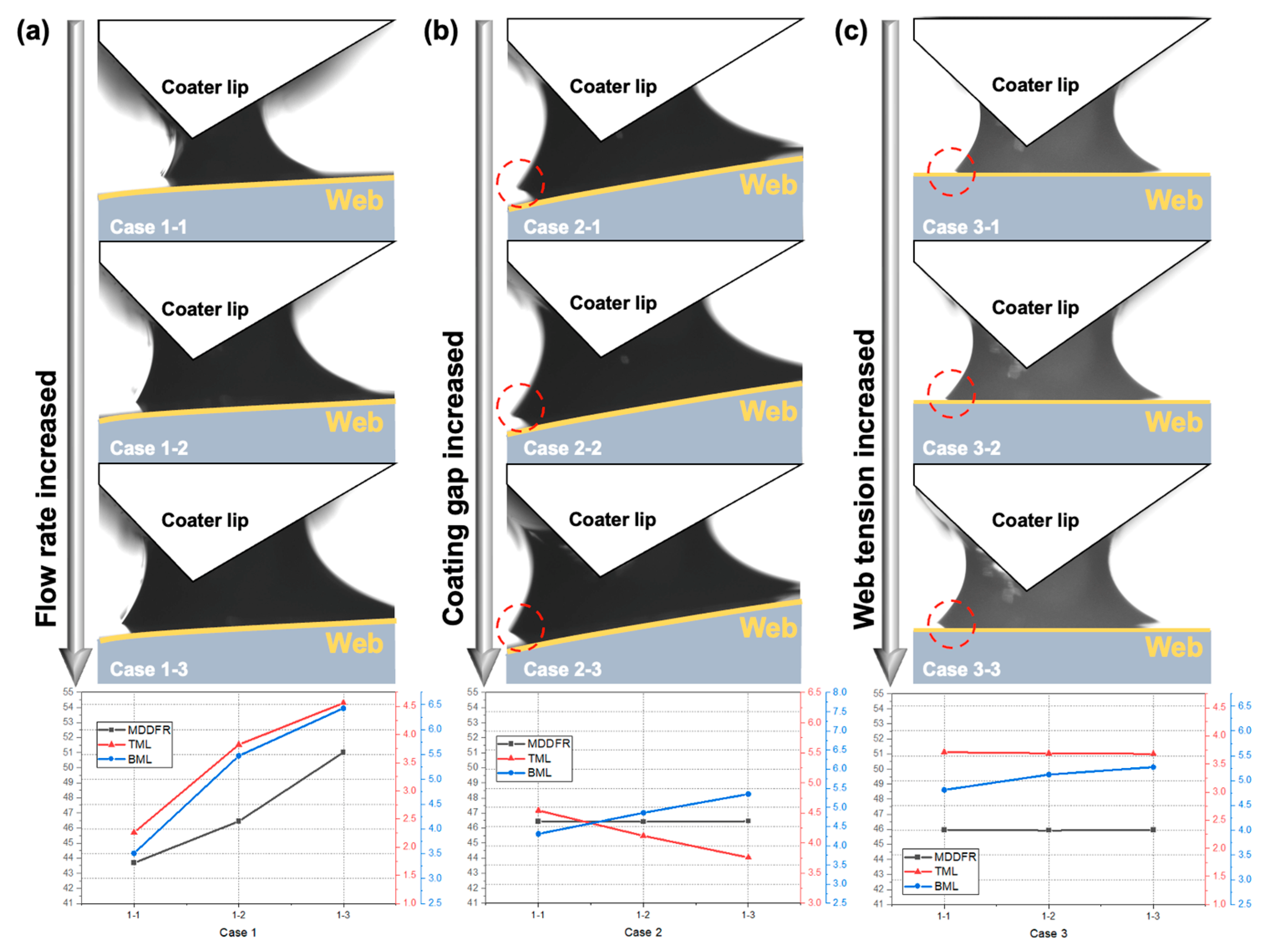
3.1. Meniscus Formation and Spreading Effect
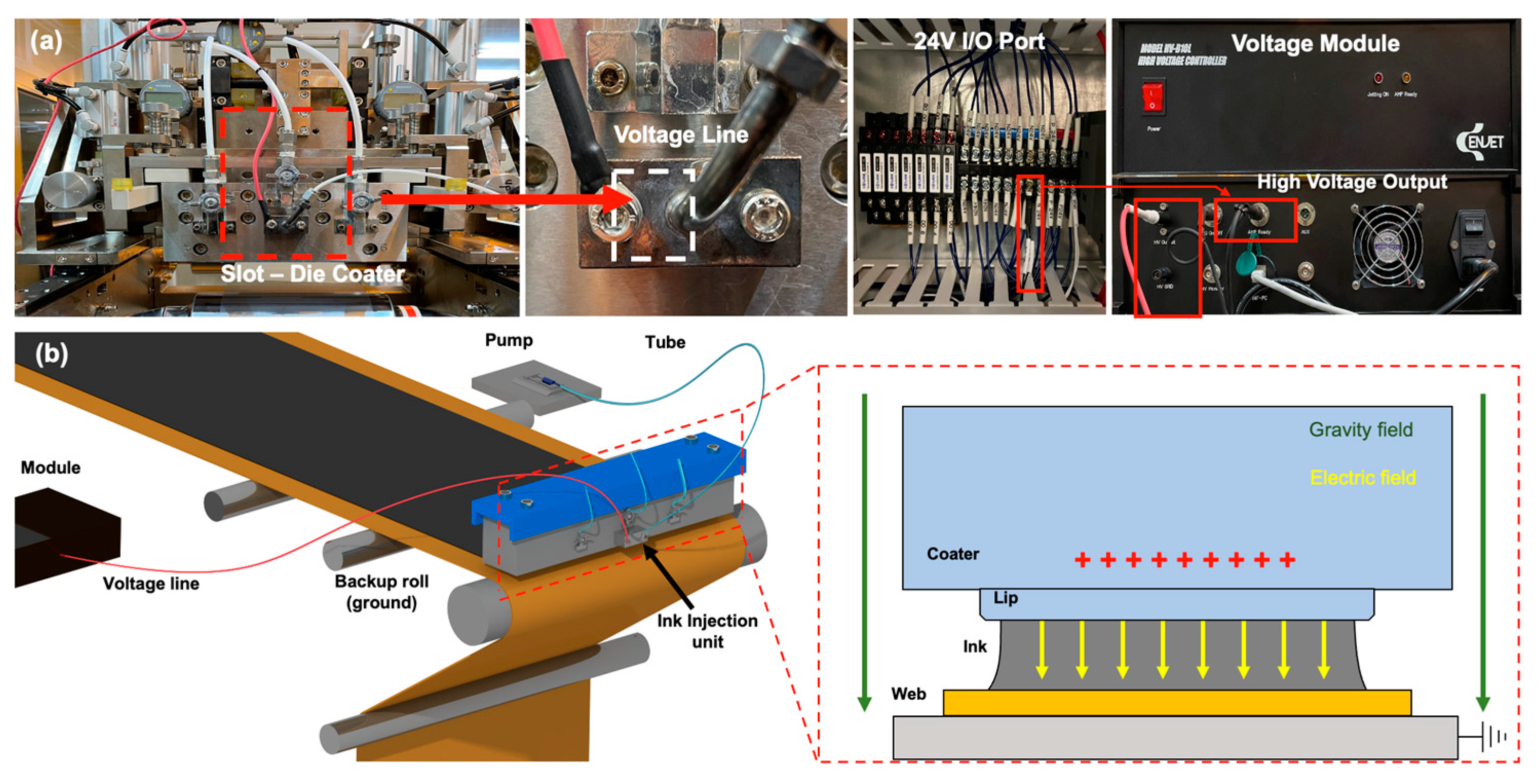
3.2. Electrohydrodynamics Module on Slot-Die Coater
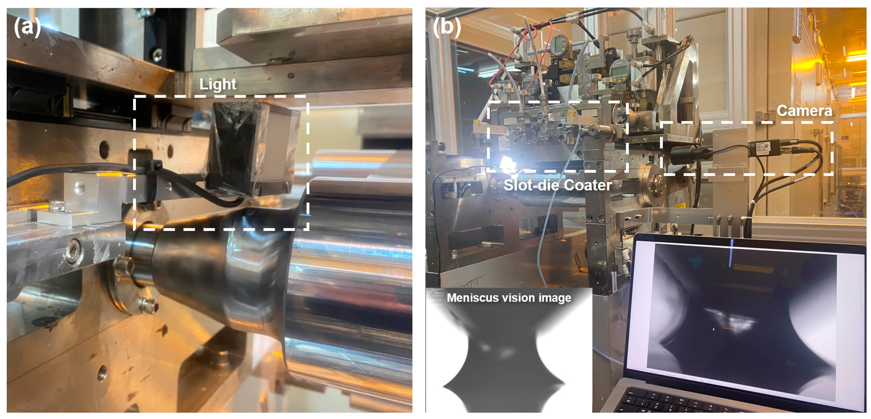
4. Experimental Setup
5. Results and Discussion
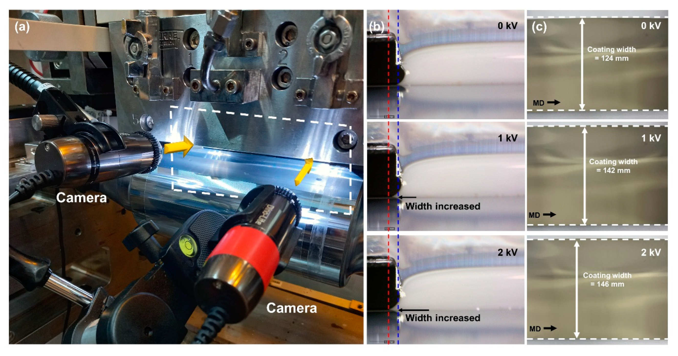
5.1. Effect of EHDs on Coating Meniscus
5.2. Coating Bead Stabilization
5.3. Electrical Conductivity of Ink
6. Conclusions
Author Contributions
Funding
Institutional Review Board Statement
Informed Consent Statement
Data Availability Statement
Conflicts of Interest
References
- Yang, C.; Ma, H.; Yuan, R.; Wang, K.; Liu, K.; Long, Y.; Xu, F.; Li, L.; Zhang, H.; Zhang, Y.; et al. Roll-to-Roll Prelithiation of Lithium-Ion Battery Anodes by Transfer Printing. Nat. Energy 2023, 8, 703–713. [Google Scholar] [CrossRef]
- Liang, H.L.; Bay, M.M.; Vadrucci, R.; Barty-King, C.H.; Peng, J.; Baumberg, J.J.; De Volder, M.F.L.; Vignolini, S. Roll-to-Roll Fabrication of Touch-Responsive Cellulose Photonic Laminates. Nat. Commun. 2018, 9, 4632. [Google Scholar] [CrossRef] [PubMed]
- Phung, T.H.; Gafurov, A.N.; Kim, I.; Kim, S.Y.; Kim, K.M.; Lee, T.M. IoT Device Fabrication Using Roll-to-Roll Printing Process. Sci. Rep. 2021, 11, 19982. [Google Scholar] [CrossRef] [PubMed]
- Bae, S.; Kim, H.; Lee, Y.; Xu, X.; Park, J.S.; Zheng, Y.; Balakrishnan, J.; Lei, T.; Kim, H.R.; Song, Y.I.; et al. Roll-to-Roll Production of 30-Inch Graphene Films for Transparent Electrodes. Nat. Nanotechnol. 2010, 5, 574–578. [Google Scholar] [CrossRef]
- Koo, H.; Lee, W.; Choi, Y.; Sun, J.; Bak, J.; Noh, J.; Subramanian, V.; Azuma, Y.; Majima, Y.; Cho, G. Scalability of Carbon-Nanotube-based Thin Film Transistors for Flexible Electronic Devices Manufactured Using an all Roll-to-Roll Gravure Printing System. Sci. Rep. 2015, 5, 14459. [Google Scholar] [CrossRef] [PubMed]
- Park, H.; Sun, J.; Jung, Y.; Park, J.; Maskey, B.B.; Shrestha, K.; Koirala, G.R.; Parajuli, S.; Shrestha, S.; Chung, A.; et al. The First Step Towards a R2R Printing Foundry via a Complementary Design Rule in Physical Dimension for Fabricating Flexible 4-Bit Code Generator. Adv. Electron. Mater. 2020, 6, 2000770. [Google Scholar] [CrossRef]
- Kim, G.; Noh, J.; Lee, H.; Shin, J.; Lee, D. Roll-to-Roll Gravure Coating of PVDF on a Battery Separator for the Enhancement of Thermal Stability. Polymers 2023, 15, 4108. [Google Scholar] [CrossRef]
- Jeon, H.; Noh, J.; Kim, M.; Jo, M.; Nam, S.; Jo, J.; Lee, C. Control methodology for tensioned web considering thermal behavior in roll-to-roll manufacturing systems. Eng. Sci. Technol. 2023, 46, 101508. [Google Scholar] [CrossRef]
- Xu, M.; Reichman, B.; Wang, X. Modeling the Effect of Electrode Thickness on the Performance of Lithium-Ion Batteries with Experimental Validation. Energy 2019, 186, 115864. [Google Scholar] [CrossRef]
- Jo, M.; Lee, J.; Kim, S.; Cho, G.; Lee, T.; Lee, C. Resistance Control of an Additively Manufactured Conductive Layer in Roll-to-Roll Gravure Printing Systems. Int. J. Precis. Eng. Manuf. Green Technol. 2021, 8, 817–828. [Google Scholar] [CrossRef]
- Schmitt, M.; Scharfer, P.; Schabel, W. Slot Die Coating of Lithium-Ion Battery Electrodes: Investigations on Edge Effect Issues for Stripe and Pattern Coatings. J. Coat. Technol. Res. 2014, 11, 57–63. [Google Scholar] [CrossRef]
- Schmitt, M.; Baunach, M.; Wengeler, L.; Peters, K.; Junges, P.; Scharfer, P.; Schabel, W. Slot-Die Processing of Lithium-Ion Battery Electrodes–Coating Window Characterization. Chem. Eng. Process. Process Intensif. 2013, 68, 32–37. [Google Scholar] [CrossRef]
- Diehm, R.; Müller, M.; Burger, D.; Kumberg, J.; Spiegel, S.; Bauer, W.; Scharfer, P.; Schabel, W. High-Speed Coating of Primer Layer for Li-Ion Battery Electrodes by Using Slot-Die Coating. Energy Technol. 2020, 8, 2000259. [Google Scholar] [CrossRef]
- Chen, L.C.; Liu, D.; Liu, T.; Tiu, C.; Yang, C.; Chu, W.; Wan, C. Improvement of Lithium-Ion Battery Performance Using a Two-Layered Cathode by Simultaneous Slot-Die Coating. J. Energy Storage 2016, 5, 156–162. [Google Scholar] [CrossRef]
- Etiemble, A.; Besnard, N.; Adrien, J.; Tran-Van, P.; Gautier, L.; Lestriez, B.; Maire, E. Quality Control Tool of Electrode Coating for Lithium-Ion Batteries based on X-Ray Radiography. J. Power Sources 2015, 298, 285–291. [Google Scholar] [CrossRef]
- Bitsch, B.; Dittmann, J.; Schmitt, M.; Scharfer, P.; Schabel, W.; Willenbacher, N. A Novel Slurry Concept for the Fabrication of Lithium-Ion Battery Electrodes with Beneficial Properties. J. Power Sources 2014, 265, 81–90. [Google Scholar] [CrossRef]
- Huang, T.; Tan, P.; Zhong, Z.; Li, M.; Zhang, Y.; Zhou, H. Numerical and Experimental Investigation on the Defect Formation in Lithium-Ion-Battery Electrode-Slot Coating. Chem. Eng. Sci. 2022, 258, 117744. [Google Scholar] [CrossRef]
- Ding, X.; Liu, J.; Harris, T.A.L. A Review of the Operating Limits in Slot Die Coating Processes. AIChE J. 2016, 62, 2508–2524. [Google Scholar] [CrossRef]
- Khandavalli, S.; Rothstein, J.P. The Effect of Shear-Thickening on the Stability of Slot-Die Coating. AIChE J. 2016, 62, 4536–4547. [Google Scholar] [CrossRef]
- Park, J.; Shin, K.; Lee, C. Roll-to-Roll Coating Technology and Its Applications: A Review. Int. J. Precis. Eng. Manuf. 2016, 17, 537–550. [Google Scholar] [CrossRef]
- Kang, H.; Park, J.; Shin, K. Statistical analysis for the manufacturing of multi-strip patterns by roll-to-roll single slot-die systems. Comput.-Integr. Manuf. 2014, 30, 363–368. [Google Scholar] [CrossRef]
- Park, J.; Shin, K.; Lee, C. Improvement of cross-machine directional thickness deviation for uniform pressure-sensitive adhesive layer in roll-to-roll slot-die coating process. Int. J. Precis. Eng. Manuf. 2015, 16, 937–943. [Google Scholar] [CrossRef]
- Huang, Y.; Cha, H.; Huang, S.; Li, C.; Santiago, S.; Tsao, C. Highly Efficient Flexible Roll-to-Roll Organic Photovoltaics Based on Non-Fullerene Acceptors. Polymers 2023, 15, 4005. [Google Scholar] [CrossRef] [PubMed]
- Hanyak, M.; Darthuber, A.; Ren, M. Surfactant-induced delay of leveling of inkjet-printed patterns. J. Appl. Phys. 2011, 109, 074905. [Google Scholar] [CrossRef]
- Liu, Y.; Zhu, H.; Xing, L.; Bu, Q.; Ren, D.; Sun, B. Recent Advances in Inkjet-Printing Technologies for Flexible/Wearable Electronics. Nanoscale 2023, 15, 6025–6051. [Google Scholar] [CrossRef] [PubMed]
- Zettl, M.; Winter, C.; Mantanus, J.; Hadjittofis, E.; Rome, S.; Leitinger, G.; Hsiao, W.K.; Roblegg, E.; Pinto, J.T.; Spoerk, M. Needles to Spheres: Evaluation of Inkjet Printing as a Particle Shape Enhancement Tool. Eur. J. Pharm. Biopharm. 2023, 184, 92–102. [Google Scholar] [CrossRef] [PubMed]
- Li, Y.; Cao, C.; Feng, F.; Fang, K.; Wang, M.; Xie, R.; Zhao, Z.; Chen, W. High-Performance Inkjet Printing Ink: Properties and Application Effects of Vinyl Sulfone Reactive Dye-based Inks. J. Mol. Liq. 2023, 369, 120864. [Google Scholar] [CrossRef]
- Kim, J.; Kim, H.; Kim, K.R.; Kang, D. Dynamics and Control of Web Handling in Roll-to-Roll System with Driven Roller. IEEE Access 2023, 11, 58159–58168. [Google Scholar] [CrossRef]
- Kim, G.E.; Kim, H.; Woo, K.; Kang, Y.; Lee, S.; Jeon, Y.; Lee, M.G.; Kwon, S. Uniform Pressing Mechanism in Large-Area Roll-to-Roll Nanoimprint Lithography Process. Appl. Sci. 2021, 11, 9571. [Google Scholar] [CrossRef]
- Parajuli, S.; Am, T.; Moon, H.; Shrestha, S.; Yang, H.; Park, J.; Jung, Y.; Lee, J.; Cho, G. Control of the Coffee Ring Effect During R2R Gravure Printing for Minimizing Threshold Voltage Variation in Printed Carbon Nanotube-based Thin Film Transistors. Mater. Today Adv. 2023, 18, 100385. [Google Scholar] [CrossRef]
- Li, S.; Kou, D.; Zhang, S.; Ma, W. Large-Area Fabrication of Structurally Colored and Humidity Sensitive Composite Nanofilm via Ultrasonic Spray-Coating. Polymers 2021, 13, 3768. [Google Scholar] [CrossRef] [PubMed]
- Seshadri, A.; Pagilla, P.R. Modeling and Control of a Rotating Turret Winder Used in Roll-to-Roll Manufacturing. Control Eng. Pract. 2015, 41, 164–175. [Google Scholar] [CrossRef]
- Dehui, W.; Chen, C.; Xiumiao, Y.; Xuesong, L.; Yimin, H. Optimization of Taper Winding Tension in Roll-to-Roll Web Systems. Text. Res. J. 2014, 84, 2175–2183. [Google Scholar] [CrossRef]
- Hashimoto, H. Optimization of Wind-Up Tension of Webs Preventing Wrinkles and Slippage. J. Manuf. Sci. Eng. 2009, 131, 0545011–0545014. [Google Scholar] [CrossRef]
- Feng, D.; Wagner, R.B.; Raman, A. Measuring Nonuniform Web Tension for Roll-to-Roll Manufacturing of Flexible and Printed Electronics. Flex. Print. Electron. 2021, 6, 035006. [Google Scholar] [CrossRef]
- Kozbial, A.; Li, Z.; Conaway, C.; McGinley, R.; Dhingra, S.; Vahdat, V.; Zhou, F.; D’Urso, B.; Liu, H.; Li, L. Study on the Surface Energy of Graphene by Contact Angle Measurements. Langmuir 2014, 30, 8598–8606. [Google Scholar] [CrossRef] [PubMed]
- Pahlevani, A.; Pahlevani, M.; Welch, G.C. Organic Light Emitting Diodes (OLEDs) with Slot-Die Coated Functional Layers. Mater. Adv. 2021, 2, 628–645. [Google Scholar] [CrossRef]
- Park, B.; Kwon, O.E.; Yun, S.H.; Jeon, H.G.; Huh, Y.H. Organic Semiconducting Layers Fabricated by Self-Metered Slot-Die Coating for Solution-Processable Organic Light-Emitting Devices. J. Mater. Chem. C 2014, 2, 8614–8621. [Google Scholar] [CrossRef]
- Ham, D.S.; Choi, W.J.; Yun, H.; Kim, M.; Yeo, D.; Lee, S.; Kim, B.J.; Lee, J.H. Influence of Drying Conditions on Device Performances of Antisolvent-Assisted Roll-to-Roll Slot Die-Coated Perovskite Solar Cells. ACS Appl. Energy Mater. 2021, 4, 7611–7621. [Google Scholar] [CrossRef]
- Pan, W.; Chen, Z.; Chen, X.; Wang, F.; Dai, G. Slot Die Coating Window for a Uniform Fuel Cell Ink Dispersion. AIChE J. 2022, 68, e17719. [Google Scholar] [CrossRef]
- Nam, J.; Carvalho, M.S. Flow in Tensioned-Web-Over-Slot Die Coating: Effect of Die Lip Design. Chem. Eng. Sci. 2010, 65, 3957–3971. [Google Scholar] [CrossRef]
- Akbarzadeh, V.; Hrymak, A.N. Coupled Fluid-Particle Modeling of a Slot Die Coating System. AIChE J. 2016, 62, 1933–1939. [Google Scholar] [CrossRef]
- Li, Y.; Yang, Q.; Li, M.; Song, Y. Rate-Dependent Interface Capture Beyond the Coffee-Ring Effect. Sci. Rep. 2016, 6, 24628. [Google Scholar] [CrossRef] [PubMed]
- Park, H.W.; Park, K.; Kwon, J.Y.; Choi, D.; Chung, K.B. Effect of Active Layer Thickness on Device Performance of Tungsten-Doped InZnO Thin-Film Transistor. IEEE Trans. Electron. Devices 2017, 64, 159–163. [Google Scholar] [CrossRef]
- Bong, W.S.K.; Shiota, A.; Miwa, T.; Morino, Y.; Kanada, S.; Kawamoto, K. Effect of thickness and uniformity of LiNbO3-coated layer on LiNi0.5Co0.2Mn0.3O2 cathode material on enhancement of cycle performance of full-cell sulfide-based all-solid-state batteries. J. Power Sources 2023, 577, 233259. [Google Scholar] [CrossRef]
- Ruschak, K.J. Limiting flow in a pre-metered coating device. Chem. Eng. Sci. 1976, 31, 1057–1060. [Google Scholar] [CrossRef]
- Schmitt, M.; Diehm, R.; Scharfer, P.; Schabel, W. An experimental and analytical study on intermittent slot die coating of viscoelastic battery slurries. J. Coat. Technol. Res. 2015, 12, 927–938. [Google Scholar] [CrossRef]
- Lin, C.F.; Wang, B.K.; Tiu, C.; Liu, T.J. On the Pinning of Downstream Meniscus for Slot Die Coating. Adv. Polym. Technol. 2013, 32, E249–E257. [Google Scholar] [CrossRef]
- Hassan, R.U.; Khalil, S.M.; Khan, S.A.; Ali, S.; Moon, J.; Cho, D.H.; Byun, D. High-resolution, transparent, and flexible printing of polydimethylsiloxane via electrohydrodynamic jet printing for conductive electronic device applications. Polymers 2022, 14, 4373. [Google Scholar] [CrossRef]
- Jiang, C.; Wang, K.; Jiang, X.; Zhang, C.; Wang, B. Quantitative Investigation of the Process Parameters of Electrohydrodynamic Direct-Writing and Their Effects on Fiber Surface Roughness and Cell Adhesion. Polymers 2020, 12, 2475. [Google Scholar] [CrossRef]
- Li, Y.; Makita, Y.; Zhang, G.; Rui, G.; Li, Z.; Zong, G.; Miyoshi, T.; Huang, H.; Zhu, L. Effects of Rigid Amorphous Fraction and Lamellar Crystal Orientation on Electrical Insulation of Poly(ethylene terephthalate) Films. Macromolecules 2020, 53, 3967–3977. [Google Scholar] [CrossRef]
- Jeon, J.; Noh, J.; Jo, M.; Joo, C.; Jo, J.; Lee, C. Layer-by-Layer Engineered Flexible Functional Film Fabrication with Spreadability Control in Roll-to-Roll Manufacturing. Polymers 2023, 15, 2478. [Google Scholar] [CrossRef]
- An, S.; Lee, M.; Kim, N.; Lee, C.; Al-Deyab, S.S.; James, S.C.; Yoon, S.S. Effect of viscosity, electrical conductivity, and surface tension on direct-current-pulsed drop-on-demand electrohydrodynamic printing frequency. Appl. Phys. Lett. 2014, 105, 21. [Google Scholar] [CrossRef]
- Carre, A.; Shanahan, M.E.R. Direct Evidence for Viscosity-Independent Spreading on a Soft Solid. Langmuir 1995, 11, 24–26. [Google Scholar] [CrossRef]
- Kwok, D.Y.; Neumann, A.W. Contact Angle Measurement and Contact Angle Interpretation. Adv. Colloid Interface Sci. 1999, 81, 167–249. [Google Scholar] [CrossRef]


| Parameter | Unit | Value | |
|---|---|---|---|
| Process conditions | Shim plate thickness | 100 | |
| Coating width | 120 | ||
| Web speed | 0.5 | ||
| Coating gap | 100 | ||
| Flow rate | 0.5 | ||
| Ink properties (JS-A101A, NOVACENTRIX.Inc., Austin, TX, USA) | Ink viscosity | 10 | |
| Weight percent | % | 40 | |
| Conductivity | 12.82 | ||
| Surface tension | 19 | ||
| Solvent properties (DI Water) | Ink viscosity | 1 | |
| Assay | % | 99 | |
| Surface tension | 73 | ||
| Relative dielectric constant | 80 | ||
| Substrate properties (CD901, KOLON.Inc., Seoul, Republic of Korea) | Thickness | 100 | |
| Width | 150 | ||
| Young’s Modulus | G | 3.19 | |
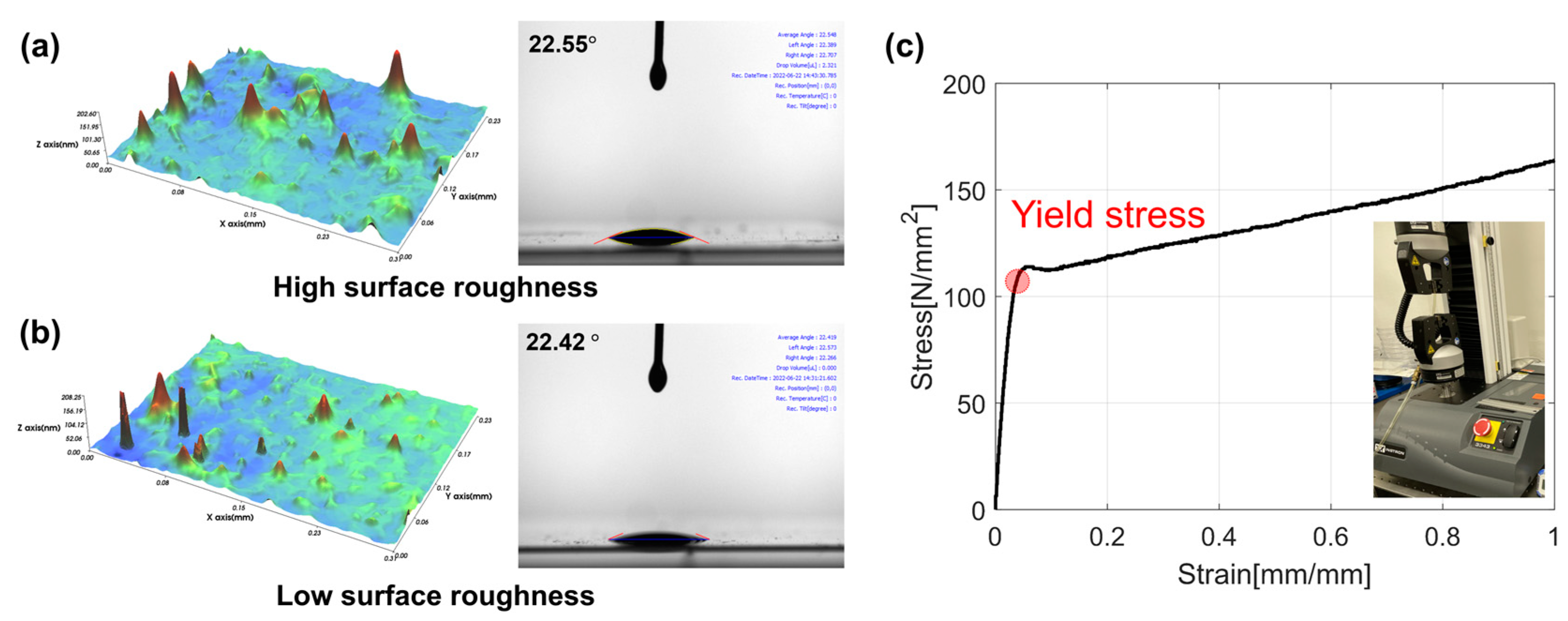
| Yield stress | 109.7 |
| Parameter | Unit | Value |
|---|---|---|
| Shim plate thickness | 100 | |
| Coating width | 120 | |
| Web speed | 5 (Stable coating) 10 (Unstable coating) | |
| Coating gap | 100 |
| Case | Flow Rate ] | Coating Gap ] | Web Tension ] | MDDFR | TML | BML |
|---|---|---|---|---|---|---|
| 1–1 | 3 | 200 | 3.7 | 43.69 | 2.26 | 3.51 |
| 1–2 | 4 | 46.44 | 3.82 | 5.47 | ||
| 1–3 | 5 | 51.02 | 4.56 | 6.43 | ||
| 2–1 | 4 | 50 | 2.7 | 46.44 | 4.64 | 4.31 |
| 2–2 | 100 | 46.41 | 4.12 | 4.86 | ||
| 2–3 | 150 | 46.45 | 3.76 | 5.35 | ||
| 3–1 | 4 | 200 | 0.7 | 45.96 | 3.71 | 4.81 |
| 3–2 | 2.7 | 45.92 | 3.69 | 5.12 | ||
| 3–3 | 4.7 | 45.95 | 3.68 | 5.27 |
| Process Variable | Unit | Value |
|---|---|---|
| Coating gap | 100 | |
| Web speed | 0.5 | |
| Ink viscosity | 10 | |
| Flow rate | 1.5 | |
| Drying temperature | 90 | |
| Operating tension | 2 | |
| Voltage | 0, 1, 2 |
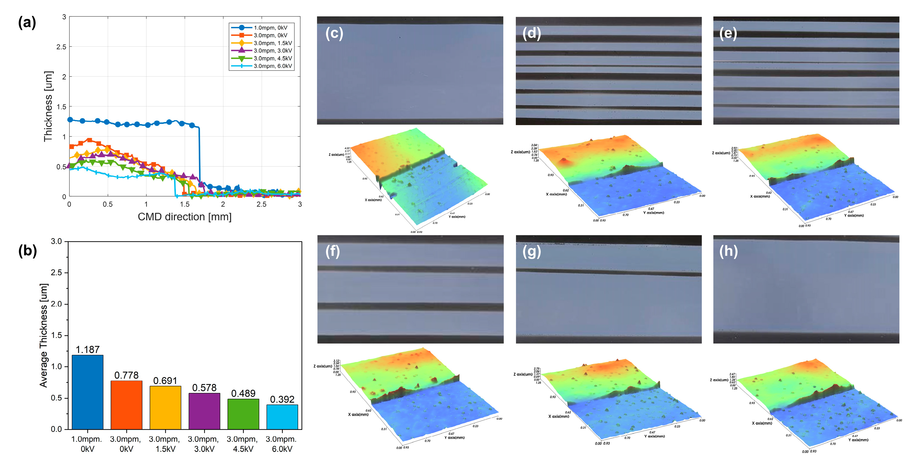
| Process Variable | Unit | Case 1 | Case 2 | Case 3 | Case 4 | Case 5 | Case 6 |
|---|---|---|---|---|---|---|---|
| Ink viscosity | 10 | 10 | 10 | 10 | 10 | 10 | |
| Coating gap | 100 | 100 | 100 | 100 | 100 | 100 | |
| Flow rate | 1.5 | 1.5 | 1.5 | 1.5 | 1.5 | 1.5 | |
| Drying temperature | 90 | 90 | 90 | 90 | 90 | 90 | |
| Operating tension | 2 | 2 | 2 | 2 | 2 | 2 | |
| Web speed | 1.0 | 3.0 | 3.0 | 3.0 | 3.0 | 3.0 | |
| Voltage | 0 | 0 | 1.5 | 2.0 | 2.5 | 2.8 |
| Applied Voltage | 0 kV | 1 kV | 2 kV |
|---|---|---|---|
| MDDFR (std) | 38.74 (0.02) | 38.79 (0.03) | 38.76 (0.02) |
| TML (std) | 1.35 (0.01) | 1.30 (0.01) | 1.28 (0.03) |
| BML (std) | 1.88 (0.01) | 2.39 (0.01) | 2.85 (0.01) |
| Parameter | Unit | Value | |
|---|---|---|---|
| Ink properties (PD-100, Paru.Inc.) | Ink viscosity | 30 | |
| Weight percent | % | 40 | |
| Surface tension | 32 | ||
| Relative dielectric constant | 20 | ||
| Solvent properties (diethylene glycol monoethyl ether acetate, Duksan.Inc., Chungbuk, Republic of Korea) | Ink viscosity | 2.8 | |
| Assay | % | 99 | |
| Surface tension | 31.7 | ||
| Relative dielectric constant | 2.54 |
Disclaimer/Publisher’s Note: The statements, opinions and data contained in all publications are solely those of the individual author(s) and contributor(s) and not of MDPI and/or the editor(s). MDPI and/or the editor(s) disclaim responsibility for any injury to people or property resulting from any ideas, methods, instructions or products referred to in the content. |
© 2024 by the authors. Licensee MDPI, Basel, Switzerland. This article is an open access article distributed under the terms and conditions of the Creative Commons Attribution (CC BY) license (https://creativecommons.org/licenses/by/4.0/).
Share and Cite
Kim, M.; Jo, M.; Noh, J.; Lee, S.; Yun, J.; Cho, G.; Lee, C. Control of Meniscus Formation Using an Electrohydrodynamics Module in Roll-to-Roll Systems for the Stable Coating of Functional Layers. Polymers 2024, 16, 845. https://doi.org/10.3390/polym16060845
Kim M, Jo M, Noh J, Lee S, Yun J, Cho G, Lee C. Control of Meniscus Formation Using an Electrohydrodynamics Module in Roll-to-Roll Systems for the Stable Coating of Functional Layers. Polymers. 2024; 16(6):845. https://doi.org/10.3390/polym16060845
Chicago/Turabian StyleKim, Minjae, Minho Jo, Jaehyun Noh, Sangbin Lee, Junyoung Yun, Gyoujin Cho, and Changwoo Lee. 2024. "Control of Meniscus Formation Using an Electrohydrodynamics Module in Roll-to-Roll Systems for the Stable Coating of Functional Layers" Polymers 16, no. 6: 845. https://doi.org/10.3390/polym16060845