Design of Improved Metal-Organic Framework (MOF) H2 Adsorbents

Abstract
: We attempted synthesis of the hydrogen adsorption material suitable for the fuel cell vehicles (FCEVs). The designed and synthesized Cu2(3,5-Pyridinedicarboxylate)2 (=Cu2PDC2) metal complex showed an extremely high volumetric uptake density for a physisorption material, even though the specific surface area was only about 1,000 m2 g−1. Factors for high uptake properties are considered to be the increased adsorption sites per unit area, the increased adsorption energy, and the optimized design of pore shapes. High hydrogen uptake on volumetric basis is especially effective for FCEV because the tank volume is reduced. It is expected that property prediction using computational simulation and sophisticated analysis at the micro and nano levels will become an indispensable tool in the design of functional materials.1. Introduction
Global warming is an urgent issue that mankind must tackle. The huge amount of CO2 emitted by human activity is considered to be one of the leading causes of global warming. Therefore, reductions of CO2 emissions are very important problem for not only human being but also earth. One of the lowest CO2 emission vehicles is a fuel cell electric vehicle, in short, FCEV. FCEVs generate electricity by the chemical reaction of hydrogen and oxygen. FCEVs can use oxygen from air easily, but hydrogen has to be kept in high pressure hydrogen storage tank. The only substance emitted is water. FCEVs already have a cruising range and performance comparable to vehicles running on gasoline.
However, high pressure hydrogen tank is bigger and heavier than gasoline tank used for conventional gasoline engine vehicle, and the size and weight of high pressure tank prevent flexible design of FCEV and the improved fuel consumption. Therefore, the use of materials that store hydrogen with both high wt % and high vol % is being considered to make the tank lighter and smaller. Many hydrogen storage materials have been investigated so far. Some of the metal hydrides are candidate materials for hydrogen storage tank. LaNi5 systems are easy to desorb hydrogen in ambient temperature but its hydrogen storage capacity is too small for FCEV. Even bcc type alloy or AB2 type alloys are insufficient for FCEVs. Mg alloys have sufficient hydrogen capacity but the operating temperature is too high for FCEVs [1-3]. Another type of material is a hydrogen adsorbent such as a carbon material or zeolite. Adsorbents have a marked advantage over metallic systems: the heat of adsorption and desorption is remarkably smaller than that of metal hydrides. As a result, heating and cooling equipment for hydrogen storage tank (the heat management system) is not required for adsorbents, and therefore the weight of the tank system may be reduced. The drawback is the relatively small amount of hydrogen that can be absorbed per unit amount of adsorbent; an improvement in this ratio is necessary for the application of adsorbents as hydrogen storage materials.
Recently, porous metal organic frameworks (MOFs) are gaining attention because of their unique porous structures and expected functions [4]. MOFs have uniform micro-pores and they lead to expectation of high hydrogen adsorption property materials [5,6]. And there are many reports on their gas adsorption properties [7-13]. MOFs are huge molecular crystals where metallic cores are connected by organic ligands called linkers. The pore size and crystallographic system may be arbitrarily adjusted by suitably choosing the elements in the metallic cores and the organic ligands for the linkers [4,14]. This flexibility in design makes MOFs attractive.
Hydrogen adsorbents for FCEV applications must have high gravimetric (wt %) and volumetric (vol %) storage densities plus a low heat of adsorption (ΔH) to reduce the charging and discharging time. However, ΔH of current porous adsorbents are too small. For example, the ΔH of IRMOF-1 [15], is 4.8 kJ mol−1 (see Section S3 in Electronic Supplementary Information, ESI). Therefore, efforts of increasing ΔH are needed to increase adsorption capacity.
In this article, we attempted to improve both volumetric and gravimetric hydrogen density using Cu-metallic-core MOF. Both volumetric and gravimetric hydrogen uptake amounts were predicted by calculation. The potential of hydrogen uptake was verified by comparing with IRMOF-1 as a representative of MOF materials.
2. Results and Discussion
2.1. Designed MOF
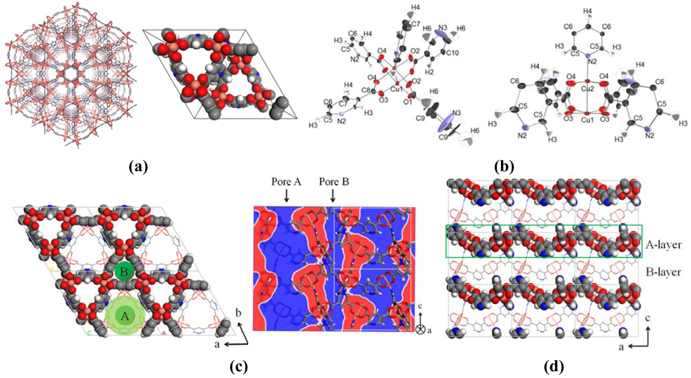
First, we analyzed various properties, including hydrogen adsorption sites, specific surface area and the amount of hydrogen adsorption for a well-known MOF (IRMOF-1 [15]) in order to predict suitable structures for hydrogen adsorption. Neutron diffraction measurements were performed to obtain adsorption sites; the result showed that the main sites were around the metallic cores [16]. Taking advantage of its design flexibility, the MOF structure shown in [Figure 1(a)], Cu2(3,5-pyridinedicarboxylate)2 (=Cu2PDC2), was designed specifically for target of supporting high volumetric and gravimetric hydrogen uptake. The structure of Cu2PDC2 is based on a basic framework of Cu and bent PDC [Figure 1(b)]. This basic framework connects two-dimensionally to form a sheet with two types of pores with sizes of approximately 6 and 11 Å [Figure 1(c)]. Cu and N in some PDC bond to form an ABAB stacking in the third dimension [Figure 1(d)]. The space group of the three-dimensional structure is P63mc. The A and B layers are rotated at an angle of 60° when viewed from the c-axis, and in consequence, each type of pore is connected through without closure [Figure 1(c)-right]. These pores become hydrogen diffusion path. One type of pore, shown as A in Figure 1(c), changes its diameter continuously from 6 to 11 Å, and the other pore B has a diameter of 6 Å and they are both connected to each other. The ratio of pore A and pore B concentration is A/B = 2. Table 1 shows the density of adsoption sites, pore ratio, and adsorption energy estimated from the crystal structure of Cu2PDC2. Adsorption energies were calculated [17-19] with first principle calculations based on density functional theory [20]. The pore volume is estimated to be less than 0.5 cm3 g−1, and the volumetric density of adsorption sites was targeted to be twice of that of IRMOF-1. While the crystal structure itself is porous, the atomic positions are precisely determined, and the pore ratio is approximately 1/2. Furthermore, as the adsorption energy of hydrogen is higher than that for IRMOF-1, an increase in adsorption per volume is expected.
The following are the characteristics of Cu2PDC2 that we designed to provide improved hydrogen storage properties: (1) The metallic cores, which are major adsorption sites [16], were placed with a high volumetric density. The use of long linker ligands in conventional MOFs to increase specific surface area [15] lead a decrease of volumetric hydrogen uptake; (2) Linkers containing N were used to localize electrons to increase the adsorption energy; (3) A paddle wheel-shaped structure that exposes much of the metallic core was selected; (4) ABAB stacking was chosen to stabilize the exposed metallic core sites as open sites. Finally, Bent linkers were used (5) to form a triangular pore structure to connect pores and (6) to form a triangular paddle-wheel structure (For details of the MOF design process, see Section S1 in ESI).
2.2. Characterization
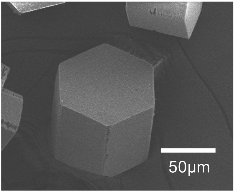
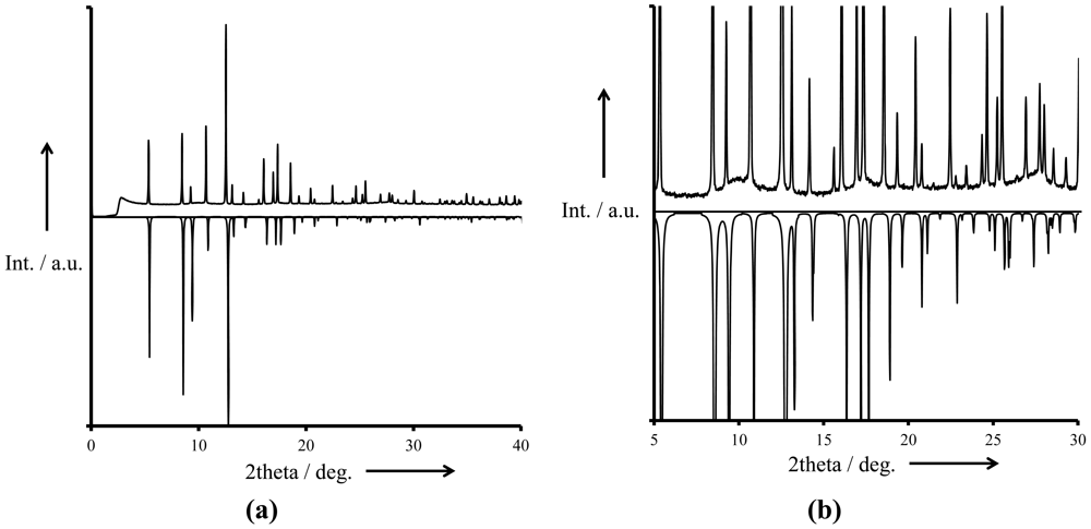
The Cu2PDC2 metal complex was synthesized from copper acetate and PDC as precursors. (For details of the synthesis process, see Experimental Section) SEM image of the synthesized Cu2PDC2 crystal is provided in Figure 2. The crystals are hexagonal prisms which reflect the P63mc symmetry of the framework. The XRPD result of synthesized crystal measured in SPring-8 indicates almost the same diffraction pattern based on Figure 1 structure (Figure 3). Furthermore, the XRPD diffraction peak positions detected with high intensity X-rays at SPring-8 was almost a perfect match to the positions of simulated diffracted peaks [Figure 3(b)], implying an extremely high purity of the sample. Rietveld refinement showed the spectrum is best approximated by a perfect structure with no defects, implying the crystal has very few defects. The difference in peak intensity of the spectrum obtained with XRPD and the simulated spectrum was derived from residual solvents such as DMF in the pores (For details on XRPD and the Rietveld refinement see Sections S6, S7 in ESI).
The specific surface area and pore diameters were measured with an ASAP2020 (Shimadzu, Japan) apparatus. The measured specific surface area was 1,003 m2 g−1 using the BET method, and 1,033 m2 g−1 with the Langmuir adsorption isotherm. The median cylindrical pore diameter based on the Horvath-Kawazoe method [21,22] was 8.9 Å. The specific surface area is relatively high because the crystal is porous, but is lower than that of MOFs designed to have a high specific area [23-26]. Pore diameters in theory are 6 and 11 Å, respectively. However the measured value takes an intermediate value of the two diameters.
2.3. Hydrogen Storage
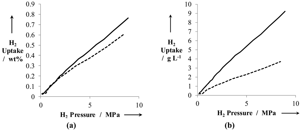
The amount of hydrogen uptake is obtained from a pressure-composition-temperature (PCT) measurement (Suzuki Shokan Co., Ltd., Japan, PCT measurement apparatus). Figure 4(a) shows the amount of hydrogen uptake at 293 K (wt %), and Figure 4(b) gives the mass of hydrogen uptake per unit volume of the crystal at 293 K (g L−1). The maximum hydrogen uptake is 0.77 wt % at 8.92 MPa from [Figure 4(a)]. The hydrogen uptake of the proposed material is clearly higher than that of conventional IRMOF-1 (dashed line), proving that our design strategy was successful. Figure 4(b) indicates that the maximum mass of adsorbed hydrogen was 9.23 g L−1, twice of that of IRMOF-1. This is an extremely high value for a physisorption material. High hydrogen uptake per unit volume significantly contributes to reducing the volume of the tank of vehicles (Hydrogen uptake considering in-vehicle condition and low temperature storage properties are explained in Sections S4-a and S4-b in ESI).
The adsorption energy of Cu2PDC2 based on a van't Hoff plot of adsorption isotherms at various temperatures was 6.0 kJ mol−1, which is approximately 1 kJ mol−1 larger than IRMOF-1 (Table 1). The adsorption energy was smaller than that we originally predicted. However, the adsorption energy is essentially same as predicted, that means larger than that of IRMOF-1.
The hydrogen uptake per unit volume of Cu2PDC2 seen in [Figure 4(b)] is double of that of IRMOF-1 although the specific surface area is about 1,000 m2 g−1, one-third to one-fourth of IRMOF-1. Both volumetrically and gravimetrically high uptakes are considered to be the two-fold increasing in adsorption sites per unit volume, the high adsorption energy, and in hydrogen adsorption efficiency by continuous combination of small and large pore sizes.
3. Experimental Section
3.1. Cu2PDC2 Synthesis
The proposed Cu2PDC2 metal complex was synthesized by combining 9.89 mL of DMF(CAS No.68-12-2), 51.3 mg of copper(II) acetate monohydrate (CAS No.6046-93-1), and 85.9 mg of PDC (3,5-pyridinedicarboxylic Acid; CAS No.499-81-0) and performing ultrasonic dissolution. Crystals were obtained by adding 0.11ml of acetic acid (CAS No.64-19-7) and keeping at 70 °C for one week. Repeated solvent replacement with CHCl3 (trichloromethane; CAS No.67-66-3) was conducted to remove guest molecules. The obtained crystals were relatively uniform, with length slightly less than 100 μm and width approximately 50 μm.
The Cu2PDC2 crystal structure has been deposited at The Cambridge Crystallographic Data Centre as CCDC 791274.
Crystal data details for Cu2PDC2:
Empirical Formula; H9Cu2O10.80N2C14 (with some guest solutions)
Formula Weight; 505.12
Crystal Colour; emerald green
Crystal Dimensions; 0.05 × 0.03 × 0.02 mm
Crystal System; hexagonal
Lattice Parameters; a = 18.9975(10) Å, c = 13.4566(9) Å
Space Group; P63mc (#186)
Dcalc; 1.196 g cm−3
4. Conclusions
MOF hydrogen adsorbents for specific use in vehicle applications should be designed according to the following characteristic criteria: (1) Hydrogen uptake should be increased not only by increasing the specific surface area per unit weight, but also by increasing both the volumetric and gravimetric uptake density, in other words by increasing the hydrogen adsorption site density as much as possible; (2) The dead space in the MOF should be minimized, which can be achieved by reducing the number of atoms in the metallic core; (3) Hetero rings or atoms with high electronegativity are introduced to increase electron localization for further improvement in adsorption energetics; (4) Enough and suitable space for hydrogen diffusion should be secured by reducing pores that become dead space and increasing diffusion speed.
It is expected that property prediction using computational simulation and a sophisticated analysis at the micro and nano level, will become an indispensable tool in determining these criteria and designing functional materials.
Supplementary Material
polymers-03-02133-s001.pdf


| Density of adsorption site/nm−3 | Pore ratio/cc cc −1 | Adsorption energy/kJ mol−1 | |||
|---|---|---|---|---|---|
| Calc. [b,d] | Calc. [c] | Exp. [d] | Calc. [a] | Exp. [d] | |
| IRMOF-1 | 3.8 | 0.77 | 0.86 | −9.4 | −4.8 |
| Cu2PDC2 | 8.9 | 0.50 | 0.49 | −16.5 | −6.0 |
[a]Calculations for typical adsorption sites. The value is the average for all estimated sites The adsorption energy tends to be overestimated in DFT calculations [16] (see Section S2 in ESI);[b]Calculated for typical sites with large adsorption energy;[c]Calculated from Connoly surface basis with Accelrys Materials Studio;[d]See Section S3 in ESI.
Acknowledgments
XRPD measurements with synchrotron radiation were conducted as an industrial user on BL19B2, SPring-8. We thank Yaghi at UCLA for sincere advice on metal complexes in general, Mori at Kanagawa University for kind consultation on synthesizing the metal complexes, and Li at MIT for supporting the first principal calculations.
References and Notes
- Kanoya, I.; Suzuki, T.; Hosoe, M. Development of High-Capacity MgMH Alloy for Hydrogen Storage. Honda R&D Tech. Rev. 2002, 14, 91–98. [Google Scholar]
- Sakintuna, B.; Lamari-Darkrim, F.; Hirscher, M. Metal Hydride Materials for Solid Hydrogen Storage: A Review. Int. J. Hydrogen Energ. 2007, 32, 1121–1140. [Google Scholar]
- Schlapbach, L.; Züttel, A. Hydrogen-Storage Materials for Mobile Applications. Nature 2001, 414, 353–358. [Google Scholar]
- Kitagawa, S.; Kitaura, R.; Noro, S. Functional Porous Coordination Polymers. Angew. Chem. Int. Ed. 2004, 43, 2334–2375. [Google Scholar]
- Takei, T.; Kawashima, J.; Ii, T.; Maeda, A.; Hasegawa, M.; Kitagawa, T.; Ohmura, T.; Ichikawa, M.; Hosoe, M.; Kanoya, I.; Mori, W. Hydrogen Adsorption Properties of Lantern-Type Dinuclear M(BDC)(DABCO)1/2. Bull. Chem. Soc. Jpn. 2008, 81, 847–856. [Google Scholar]
- Morris, R.E.; Wheatley, P.S. Gas Storage in Nanoporous Materials. Angew. Chem. Int. Ed. 2008, 47, 4966–4981. [Google Scholar]
- Yuan, D.; Zhao, D.; Sun, D.; Zhou, H. An Isoreticular Series of Metal-Organic Frameworks with Dendritic Hexacarboxylate Ligands and Exceptionally High Gas-Uptake Capacity. Angew. Chem. Int. Ed. 2010, 49, 5357–5361. [Google Scholar]
- Rowsell, J.L.C.; Yaghi, O.M. Strategies for Hydrogen Storage in Metal-Organic Frameworks. Angew. Chem. Int. Ed. 2005, 44, 4670–4679. [Google Scholar]
- Panella, B.; Hirscher, M.; Pütter, H.; Müller, U. Hydrogen Adsorption in Metal-Organic Frameworks: Cu-MOFs and Zn-MOFs Compared. Adv. Funct. Mater. 2006, 16, 520–524. [Google Scholar]
- Furukawa, H.; Ko, N.; Go, Y.B.; Aratani, N.; Choi, S.B.; Choi, E.; Yazaydin, A.Ö.; Snurr, R.Q.; O'Keeffe, M.; Kim, J.; Yaghi, O.M. Ultrahigh Porosity in Metal-Organic Frameworks. Science 2010, 329, 424–428. [Google Scholar]
- Ma, S.; Zhou, H.C. Gas Storage in Porous Metal-Organic Frameworks for Clean Energy Applications. Chem. Commun. 2010, 46, 44–53. [Google Scholar]
- Han, S.S.; Goddard, W.A., III. Lithium-Doped Metal-Organic Frameworks for Reversible H2 Storage at Ambient Temperature. J. Am. Chem. Soc. 2007, 129, 8422–8423. [Google Scholar]
- Furukawa, H.; Miller, M.A.; Yaghi, O.M. Independent Verification of the Saturation Hydrogen Uptake in MOF-177 and Establishment of a Benchmark for Hydrogen Adsorption in Metal-Organic Frameworks. J. Mater. Chem. 2007, 17, 3197–3204. [Google Scholar]
- O'Keeffe, M.; Yaghi, O.M. Deconstructing the Crystal Structures of Metal-Organic Frameworks and Related Materials into Their Underlying Nets. Chem. Rev. 2011. [Google Scholar] [CrossRef]
- Eddaoudi, M.; Kim, J.; Rosi, N.; Vodak, D.; Wachter, J.; O'Keeffe, M.; Yaghi, O.M. Systematic Design of Pore Size and Functionality in Isoreticular MOFs and Their Application in Methane Storage. Science 2002, 295, 469–472. [Google Scholar]
- Kanoya, I.; Furuta, T.; Sakamoto, R.; Hosoe, M.; Ichikawa, M.; Itoh, K.; Fukunaga, T. Anomalous Aggregation State of Deuterium Molecules in the Nanoscale Pores of a Metal Organic Framework. J. Appl. Phys. 2010, 108, 074310. [Google Scholar]
- The calculations have been performed using the ab-initio total-energy and molecular dynamics program VASP (Vienna ab-inito simulation program) developed at the Institut fur Material-physik of the Universitat Wien.
- Kresse, G.; Furthmuller, J. Efficient Iterative Schemes for ab Initio Total-Energy Calculations Using a Plane-Wave Basis Set. Phys. Rev. B 1996, 54, 11169–11186. [Google Scholar]
- Kresse, G.; Joubert, D. From Ultrasoft Pseudopotentials to the Projector Augmented-Wave Method. Phys. Rev. B 1999, 59, 1758–1775. [Google Scholar]
- Kohn, W.; Sham, L.J. Self-Consistent Equations Including Exchange and Correlation Effects. Phys. Rev. 1965, 140, A1133–A1138. [Google Scholar]
- Horvath, G.; Kawazoe, K. Method for the Calculation of Effective Pore Size Distribution in Molecular Sieve Carbon. J. Chem. Eng. Jpn. 1983, 16, 470–475. [Google Scholar]
- Dombrowski, R.J.; Lastoskie, C.M.; Hyduke, D.R. The Horvath-Kawazoe Method Revisited. Colloids Surf. 2001, 187-188, 23–39. [Google Scholar]
- Rowsell, J.L.C.; Millward, A.R.; Park, K.S.; Yaghi, O.M. Hydrogen Sorption in Functionalized Metal-Organic Frameworks. J. Am. Chem. Soc. 2004, 126, 5666–5667. [Google Scholar]
- Rowsell, J.L.C.; Yaghi, O.M. Effects of Functionalization, Catenation, and Variation of the Metal Oxide and Organic Linking Units on the Low-Pressure Hydrogen Adsorption Properties of Metal-Organic Frameworks. J. Am. Chem. Soc. 2006, 128, 1304–1315. [Google Scholar]
- Ferey, G.; Mellot-Draznieks, C.; Serre, C.; Millange, F.; Dutour, J.; Surble, S.; Margiolaki, I. A Chromium Terephthalate-Based Solid with Unusually Large Pore Volumes and Surface Area. Science 2005, 309, 2040–2042. [Google Scholar]
- Ma, S.; Sun, D.; Ambrogio, M.; Fillinger, J.A.; Parkin, S.; Zhou, H.-C. Framework-Catenation Isomerism in Metal-Organic Frameworks and Its Impact on Hydrogen Uptake. J. Am. Chem. Soc. 2007, 129, 1858–1859. [Google Scholar]
© 2011 by the authors; licensee MDPI, Basel, Switzerland. This article is an open access article distributed under the terms and conditions of the Creative Commons Attribution license (http://creativecommons.org/licenses/by/3.0/).
Share and Cite
Furuta, T.; Kanoya, I.; Sakai, H.; Hosoe, M. Design of Improved Metal-Organic Framework (MOF) H2 Adsorbents. Polymers 2011, 3, 2133-2141. https://doi.org/10.3390/polym3042133
Furuta T, Kanoya I, Sakai H, Hosoe M. Design of Improved Metal-Organic Framework (MOF) H2 Adsorbents. Polymers. 2011; 3(4):2133-2141. https://doi.org/10.3390/polym3042133
Chicago/Turabian StyleFuruta, Terumi, Izuru Kanoya, Hiroshi Sakai, and Mitsuya Hosoe. 2011. "Design of Improved Metal-Organic Framework (MOF) H2 Adsorbents" Polymers 3, no. 4: 2133-2141. https://doi.org/10.3390/polym3042133