Article

A Turbulence-Oriented Approach to Retrieve Various Atmospheric Parameters Using Advanced Lidar Data Processing Techniques

by
Iulian-Alin Rosu
1,
Marius-Mihai Cazacu
2,*,
Otilia Sanda Prelipceanu
1,3 and
Maricel Agop
2
1
Alexandru Ioan Cuza University of Iasi, Faculty of Physics, Bulevardul Carol I 11, 700506 Iași, Romania
2
Gheorghe Asachi Technical University of Iasi, Department of Physics, 700050 Iași, Romania
3
Alexandru Ioan Cuza University of Iasi, Integrated Center of Environmental Science Studies in the North-Eastern Development Region (CERNESIM), 700506 Iasi, Romania
*
Author to whom correspondence should be addressed.
Atmosphere 2019, 10(1), 38; https://doi.org/10.3390/atmos10010038
Submission received: 17 November 2018 / Revised: 12 January 2019 / Accepted: 14 January 2019 / Published: 18 January 2019
(This article belongs to the Special Issue Remote Sensing of Aerosols)

Abstract

:
The article is aimed at presenting a semi-empirical model coded and computed in the programming language Python, which utilizes data gathered with a standard biaxial elastic lidar platform in order to calculate the altitude profiles of the structure coefficients of the atmospheric refraction index C N 2 ( z ) and other associated turbulence parameters. Additionally, the model can be used to calculate the PBL (Planetary Boundary Layer) height, and other parameters typically employed in the field of astronomy. Solving the Fernard–Klett inversion by correlating sun-photometer data obtained through our AERONET site with lidar data, it can yield the atmospheric extinction and backscatter profiles α ( z ) and β ( z ) , and thus obtain the atmospheric optical depth. Finally, several theoretical notions of interest that utilize the solved parameters are presented, such as approximated relations between C N 2 ( z ) and the atmospheric temperature profile T ( z ) , and between the scintillation of backscattered lidar signal and the average wind speed profile U ( z ) . These obtained profiles and parameters also have several environmental applications that are connected directly and indirectly to human health and well-being, ranging from understanding the transport of aerosols in the atmosphere and minimizing the errors in measuring it, to predicting extreme, and potentially-damaging, meteorological events.

1. Introduction

Performing atmospheric altitude profiles of several atmospheric and meteorological parameters demands great financial costs, cannot be performed at any place or any time, and at present, the current theoretical models have significant limitations (reduced spatial and temporal resolutions) [1,2]. Currently, the only reliable method to directly obtain meteorological parameters throughout the free atmosphere for low to high altitudes is by launching specialized weather balloons equipped with in-situ sensors [3]. A method for continuously obtaining the altitude profiles of these parameters can be a powerful tool for weather prediction, atmospheric turbulence assessment, and for anticipating temperature inversions which can cause amplified pollution in the environment [4,5], but also for predicting extreme weather events [6], and for improving the accuracy of aerosol concentration measurements [7].
Lidar systems are utilized in the fields of high-resolution mapping, geodesy, archaeology, geography, atmospheric physics and many more. In this work, we present a new semi-empirical algorithm based on experimental elastic lidar data and complementary techniques utilized in atmospheric physics to calculate several atmospheric parameters relevant in the study of atmospheric turbulence, and its relation to astronomy, meteorology, environmental studies and human health, without using direct techniques of atmosphere probing. It is primarily based on its implementation in the programming language Python 3.6 to process the large amount of lidar data needed to measure the profiles of the RCS (Range Corrected Signal), and to calculate the structure coefficient of the atmospheric refractive index, C N 2 (z). The calculation of these parameters yields the others, and can potentially lead to a means of obtaining meteorological parameters through lidar elastic backscatter data alone.

2. Materials and Methods

The temporal variation of meteorological parameters is difficult to calculate and predict because of atmospheric turbulence; quasi-chaotic variations of flow speed and direction in turbulence make it difficult to predict these parameters using theoretical models. The mathematical description of the internal structure of turbulence remains a problem to be solved; however, several notions utilized in atmospheric physics derived from turbulence mechanics can be used to calculate some of these atmospheric parameters.

2.1. Turbulence Profiles

According to the literature, the structure coefficient of any atmospheric parameter C A 2 ( x ) is defined as:
C A 2 ( x ) = A ( x ) A ( x + d ) 2 d 2 3
with A being an atmospheric parameter at an altitude x , at two points separated by a distance d , which is oriented horizontal to the surface [5].
Many works are dedicated to new and efficient ways to empirically, or theoretically, calculate or approximate the structure coefficient profile of the atmospheric refractive index C N 2 ; most notably, the AXP [8], Tatarski–Vernin [8] and Hufnagel–Valley 5-7 [9] models attempt to yield accurate data on said coefficients through analytical means.
Experimental means to obtain C N 2 remotely do exist, as shown in multiple studies that utilize lidar techniques [10,11], although the method employed in this study appears to be more cost-effective, time-efficient, and does not require a dedicated platform; while the compact lidar platform utilized in our study yields data sufficient to construct atmospheric profiles once every 3 minutes, or less.
The structure coefficient of the refraction index C N 2 ( z ) , according to Tatarski [12], is found in the equation:
σ I 2 ( L ) = 1.23   C N 2   ( L ) k 7 6 L 11 6
with σ I 2 being the „scintilation” (or, in this case, the logarithm of the standard deviation of light intensity) of a light source observed from a distance represented by the optical path L . The definition [12]:
σ I 2 ( L ) = ln ( 1 + I ( L ) 2 I ( L ) 2 I ( L ) 2 )
is given, with I ( L ) being the intensity of the range-corrected signal at the particular point in the optical path, which is analogous with the RCS intensity.
It must be said that Equation 2 is only valid for L > l 0 2 λ , and for σ I 2 < 1 , which we find to be true for the entirety of the optical path and most meteorological conditions. We cannot precisely know the value of the Kolmogorov inner scale l 0 beforehand, however, multiple other studies [13,14,15] show that, under normal atmospheric conditions, at ground level, the inner scale is no smaller than 2 mm and no larger than 6 mm, and is larger only by a factor of 10 up to a height of 20 km, growing logarithmically. Considering the wavelength of the lidar-mounted laser, the condition L > l 0 2 λ is true for all altitudes, except closer than 10–50 m above ground level. We also find that σ I 2 < 1 is true for all cases and at all altitudes, with σ I 2 being, on average, of the order of 10 4 . Our results seem to confirm the theory, and sit well with multiple other empirical studies [10,16], and with theoretical C N 2 ( z ) profiles [8,9]. Regarding the potential influence of noise-related errors to the calculation of the scintillation profile, the overall signal uncertainty added by noise is:
V = N S F 2 ( V V b ¯ ) + ( V b ) 2
where V is raw lidar signal, V b is background lidar signal, and N S F is the “noise scale factor”, which is equal to the standard deviation of the shot noise divided by the square root of average shot noise [17]. It is determined that the signal uncertainty, in the case of attenuated backscatter, has values of the order 10 7 or lower [17], while a typical attenuated backscatter profile has values of the order 10 5 or lower; thus, this uncertainty represents variations hundreds of times smaller than the actual values of the profile. Since the model subtracts the “dark” signal (generated by photocathode thermionic emission, which we measure beforehand [18]) from the raw signal, we can assume that such uncertainty is even lower. Also, the fact that the photomultiplier component of the lidar platform utilized in this study was being operated in analogue mode removes the need to consider possible instances of “afterpulsing”, which only take place when a photomultiplier component is operated in a “pulse detection mode” [18]. Finally, the fact that the photomultiplier component of the lidar platform used in this study is a PMT (photomultiplier tube) presents an advantage, since excess noise decreases with an increase in the average photo-multiplication gain in PMTs [17].
Having determined the C N 2 ( z ) profile, it is now possible to calculate, with a degree of approximation, the turbulence-related parameters. The inner scale profile is linked to scintillation [12]:
σ I 2 ( L ) 0.615   C N 2   ( L ) L 3 l 0 ( L ) 7 3
and the outer scale is linked to the C N 2 ( z ) profile [12]:
C N 2 ( z ) = L 0 ( z ) 4 3 ( n ( z ) ¯ ) 2
If the turbulent eddies are within the inertial subrange, the refraction index profile can be approximated from the definition of its structure coefficient [12,19]:
n ( z ) n 0 C N 2 ( z ) z 2 3
which then gives us the means to extract the outer scale profile. Once the two profiles are determined, the Reynolds number profile can be estimated [19]:
R e ( z ) ( L 0 ( z ) l 0 ( z ) ) 4 3
Once again, the obtained results, even with such high degrees of approximation, seem plausible and are in accord with theoretical data.

2.2. Astronomy Parameters, Extinction and Backscatter Coefficients

Once the C N 2 ( z ) profile is obtained, a number of parameters used in astronomy can be derived. One of these is the Fried parameter (also known as the Fried coherence length) r 0 , which is a measure of the “quality” of optical transmission through the atmosphere; it quantifies the total amount of random inhomogeneity in the profile of the atmospheric refractive index representative of the given column of air. This inhomogeneity is usually credited to turbulence-related phenomena, but the parameter is used to determine a different quantity, the so-called “astronomical seeing”, which quantifies how appropriate the atmosphere is at the given moment for astronomical observation.
The Fried coherence length is defined as [20]:
r 0 =   ( 0.06   λ 2 I ( z ) ) 3 5
with I ( z ) =   0 C N 2 ( z ) d z , and the “seeing” as [21]:
ε = 0.98 λ r 0
This value is regularly used to evaluate potential astronomical site construction; the lower this quantity, the better for astronomical observation [22]. For extremely clear atmospheric conditions, a seeing of 0.4 arcseconds is usually invoked, thus in an appropriate site for astronomic observation we should observe astronomical seeing between 0.4 and 1 arcseconds. This theory presents a different avenue of utilizing lidar data; in this case, for quantifying the astronomical observation viability of a particular area at a particular time.
A different quantity used in astronomical and astroclimatic studies can also be obtained with lidar data, namely, the optical depth τ . In order to calculate it, the profile of atmospheric extinction, α ( z ) , must first be known. It is known that both the atmospheric extinction and backscatter profiles, α ( z ) and β ( z ) , contain components that quantify molecular and aerosol influence [23], and they are important factors in the well-known elastic backscatter lidar equation:
R C S ( z ) = O ( z ) K β ( z ) e 2 0 z α ( z ) d z
where O ( z ) is the overlap function, and K is the lidar constant [24].
The quantities L R m and L R a , the molecular and aerosol lidar ratios, relate to the division of the individual components of extinction and backscatter [23], and these two ratios are important because, from an elastic lidar measurement, it is not possible to directly distinguish the contributions of extinction and backscatter to the signal profile, because the relation between α ( z ) and β ( z ) varies depending upon the content of the measurement volume at the altitude z [22].
Let us define the molecular extinction coefficient as:
α m ( z ) = 8 π 3 3 ( n ( z ) 2 1 ) 2 λ 4 N S 0 2 6 + 3 δ 6 7 δ T 0 P 0 N S ( z ) P ( z ) T ( z )
with n ( z ) being the atmospheric refraction index, N S 0 the atmospheric molecule number concentration at ground level in normal conditions = 2.547 · 10 25   m o l e c u l e s / m 3 , δ the radiation depolarization factor = 0.0284   for the operating wavelength of the lidar platform used in this study ( 532 n m ), T 0 = 288.15 K , P 0 = 1013 h P a , and N S ( z ) the atmospheric molecule number concentration profile. Let us also define L R a as approximately constant [23,24,25]:
L R a   4 π w ( λ ) P ( λ ,   180 ° )
with w ( λ ) being the wavelength-dependant single scattering albedo, and P ( λ ,   180 ° ) the backscatter phase function at 180 degrees. The quantities used to establish the approximation of the aerosol lidar ratio have been obtained from data gathered with our sun-photometer (which is a part of the AERONET Iasi_LOASL site) [26,27].
Having obtained these parameters, and using theoretical data to obtain the profile of molecular extinction, we can couple them with our experimental lidar data to calculate the total backscatter coefficient profile through the backwards-integrating Fernald–Klett inversion [28], which is then used to obtain the total extinction coefficient profile, and the optical depth [29]:
τ =   0 z α ( z ) d z

2.3. Theoretical Prospects

The relation between the two structure coefficients of the refraction index and temperature is usually defined as:
C N 2 ( z ) = [ 80   P ( z ) T 2 ( z ) 10 6 ] 2 C T 2 ( z )
where P ( z ) and T ( z ) are pressure and temperature as functions of altitude [30]. A slight correction must be implemented: according to Andreas [31], if we neglect the influence of humidity in the variation of the refraction index throughout the atmosphere, we can define the structure coefficient of the refraction index as C N 2 ( z ) = A 2 C T 2 ( z ) , with A = 10 6 P T 2 m 1 ( λ ) and m 1 ( λ ) , being a function of wavelength, is equal to 23.7134 6839.397 130 λ 2 +   45.473 38.9 λ 2 [31].
The parameter m 1 ( λ ) is usually taken to be constant [9,30], and equal to 80 . However, considering the wavelength of the laser included in the lidar platform ( λ = 0.532 μ m ), we obtain m 1 ( λ ) = 79.0793   . With this small correction, we arrive at the final equation:
C N 2 ( z ) = 6.2535 · 10 9 P ( z ) 2 T ( z ) 4 C T 2 ( z )
Bringing this definition and that of the molecular backscatter together (Equation (12)), in terms of the pressure to temperature division, we approximate:
α m ( z ) 6.0024 · 10 21 N S ( z ) F ( z ) 2
with:
F ( z ) =   T ( z ) ( n ( z ) 2 1 ) C N 2 ( z ) C T 2 ( z )
Then, taking into consideration Equation (6), and approximating that significant variations of n ( z ) and T ( z ) only occur vertically, not on the horizontal plane (between a maximum distance represented by the length of L 0 at that particular altitude), F ( z ) can be defined:
F ( z )   { d d z [ n ( z ) 3 n ( z ) ] } · { d d z [ T ( z ) 3 2 ] } 1
Thus, molecular extinction can be approximated through the profiles of the atmospheric molecule number concentration, atmospheric temperature, and atmospheric refraction index.
It is also possible to construct a relation between RCS scintillation data and the average wind speed U ( z ) ; such a relation exists because higher average wind speed necessarily creates larger and faster variations of the quantity of backscattered light, thus, a larger amount of RCS scintillation. The relation would also need to contain an altitude-dependent term; it can be defined as:
U ( z ) U 0 σ ( z ) a z b
where U 0 is average wind speed at ground level, and a , b two arbitrary coefficients. We find that a = 1 5 and b =   1 7 appear to yield the most convincing results, although the equation could be improved through real balloon sounding data correlation.
Finally, we can input this theoretical wind speed profile to attempt to obtain a temperature profile through the relation outlined by Equation (15), and another between the two structure coefficients:
C N 2 ( z ) = C T 2 ( z ) 4 T 0 +   C U 2 ( z ) c 0
with C U 2 ( z ) being the structure coefficient of average wind speed, c 0 the mean value of the velocity of sound for the given atmospheric profile, and T 0 the mean air temperature for the given atmospheric profile [12]. For these two constants we have utilized the values T 0 = 243.65 K and c 0 = 312.9 m / s , and experimenting with these values has shown that small deviations produce very little variation in the following results. Given another general definition of the structure coefficient of an atmospheric parameter [12]:
C A 2 ( z ) = a 2   N A ¯   ( z ) ε 1 3 ( z )
wherein a is a numerical constant, ε ( z ) is the turbulent kinetic energy dissipation rate profile, and N A ¯ ( z ) the amount of inhomogeneity in the respective atmospheric parameter which disappears per unit of time due to molecular diffusion, we can determine C U 2 ( z ) ; the quantities ε ( z ) and N A ¯ ( z ) are synonimous in the case of average wind speed, thus:
C U 2 ( z ) = a 2 ε 2 3 ( z )
For the constant a we have implemented the value of 0.1383 . Tatarski defines the turbulent outer scale as:
L 0 ( z ) = K ( z ) β U ( z )
with K ( z ) being the coefficient of turbulent diffusion, and β U ( z ) = d U ( z ) d z [12]. Also, a relation between N A ¯ ( z ) and K ( z ) is outlined as [12]:
N A ¯ ( z ) = K ( z ) ( A ( z ) ¯ ) 2
Bringing together Equation (6) and Equation (22), we determine:
ε ( z ) = a 6 N A ¯ 3   ( z ) L 0 4 ( z ) ( A ( z ) ¯ ) 6 = a 6 L 0 2 ( z ) β U 3 ( z )
In this manner it is possible to define the turbulent kinetic energy dissipation rate profile in terms of the wind speed derivative profile, and the turbulent outer scale profile. This is then used to determine C T 2 ( z ) in Equation (21), and after utilizing a simple barometric pressure model, a semi-empirical air temperature profile can be extracted from Equation (15). Alternatively, it is possible to decrease the number of approximations necessary to obtain the outer length scale, and thus, the temperature, considering another single approximation obtained through dimensional calculus. The dimensions of ε are M L 2 T 2 M T = L 2 T 3 , and the dimensions of U are L T 1 ; this means that, if we approximate the rotation speed of the largest turbulent eddies to be the average wind speed U :
ε ( z ) U 3 ( z ) L 0 ( z )
which yields, along with Equation (26), L 0 ( z ) U ( z ) β U ( z ) . Thus, it is possible to construct the turbulent kinetic energy dissipation rate profile strictly from the average wind speed profile and its derivative, which results in a more accurate air temperature profile.

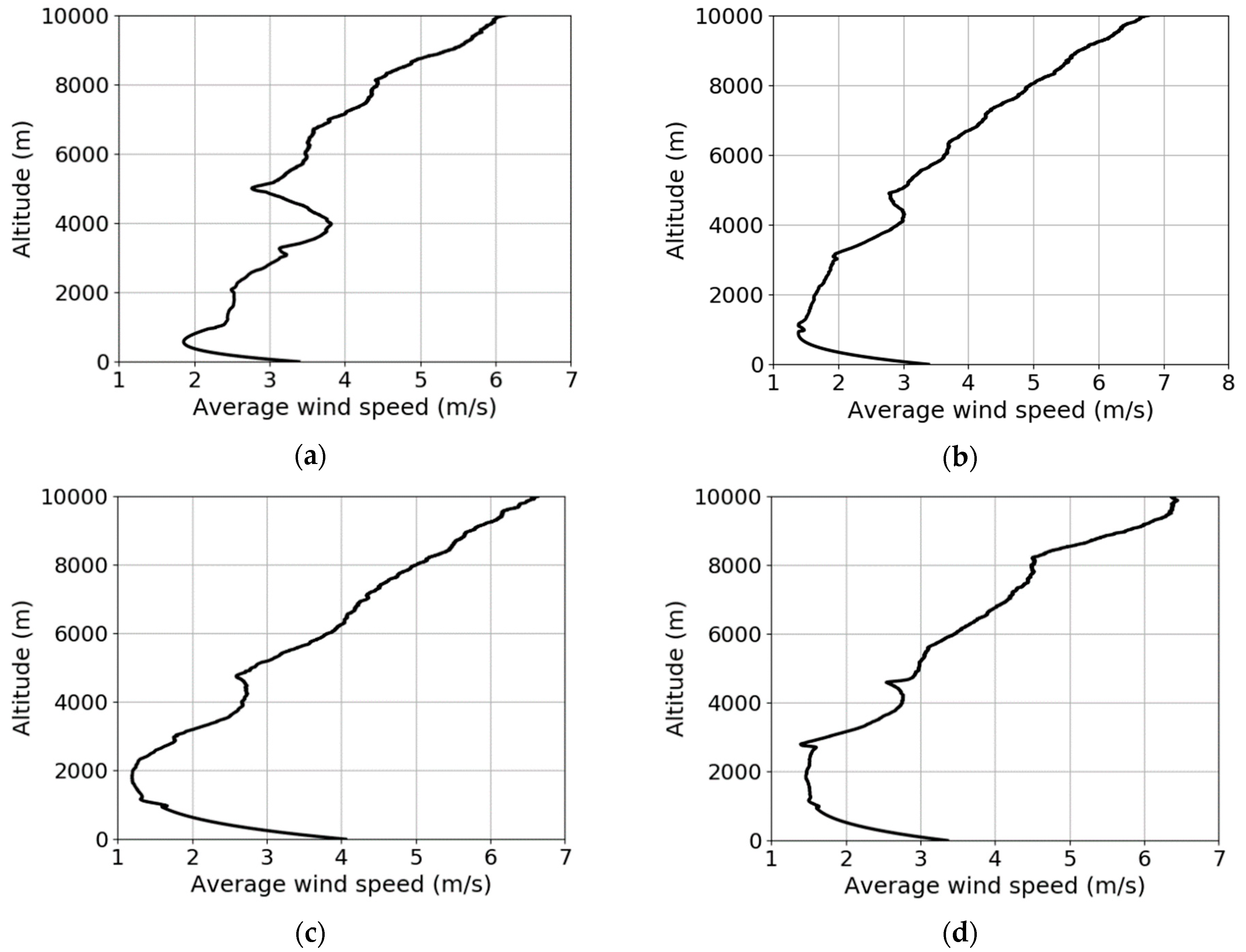
3. Results and Discussions

3.1. Results

The following profiles have been made analyzing lidar RCS data obtained and compiled on 28 May 2017 (Figure 1a–c) at the LOASL (Optical Atmosphere Spectroscopy and Lasers Laboratory), part of the Faculty of Physics in the “Alexandru Ioan Cuza” University, at the coordinates 47.19306 °   N o r t h and 27.55556 °   E a s t .
The technical specifications of the main components of the lidar platform utilized in the study are as follows: the laser component is a Nd:YAG, producing pulses of laser at a frequency of 30 H z , with a wavelength of 532 n m , laser beam diameter of 6 m m and a pulse energy of 100 m J ; meanwhile, the optical component is a Newtonian LightBridge telescope with a primary mirror diameter of 406 m m . The lidar platform utilized in the study has a spatial resolution of 3.75 m and both technical details and results from previous measurement campaigns were reported in the scientific literature [32,33].
With this particular setup and platform, we require three minutes-worth of RCS data to calculate the altitude profile of the logarithm of the standard deviation of light intensity, and we consider that time period short enough to construct the profiles with minimal error. Temperature profiling obtained with a higher rate of acquisition (45 seconds) temporal resolution of 45 seconds has also been exemplified, in order to ascertain whether or not the rate of RCS profile acquisition has a substantial impact on the calculations. We found that a lower temporal resolution yields a temperature profile that is more accurate; this is because Equation (26) relies on the approximation that the total amount of parameter inhomogeneity in the atmospheric column is constant, which is only true for small intervals of time. This is seen in the comparison of the temperature profiles that are presented below; they are calculated with a 45 second temporal resolution. However, such an increase in profile acquisition rate can have multiple disadvantages: an increased pulse frequency is accompanied by greater signal shot noise, and smaller range.
We here present RCS, C N 2 ( z ) , turbulence scales, backscatter and semi-empirical average wind profiles obtained for the mentioned date of measurement (Figure 2, Figure 3, Figure 4, Figure 5, Figure 6 and Figure 7).
The time-series of the RCS profiles help establish a quick evaluation of the atmosphere, acting as the main guide to select certain chunks of data for further analysis (Figure 1). C N 2 ( z ) profiles exhibit the expected order of value and shape [9], while also spiking in the region of the PBL (Figure 3), and despite the approximations, the l 0 ( z ) and L 0 ( z ) , and the R e ( z ) profiles are also encouraging (Figure 4 nad Figure 5), with perhaps the L 0 ( z ) profiles showing slightly smaller values than most other studies [14]. The aerosol backscatter profile presents values that are at least twice as large as those accounted by molecular backscatter in the region of the PBL, but that is to be expected in the context of a large city climate and aerosol conditions (Figure 6). Temperature profiles and RCS time series associated with the profiling intervals are presented in Figure 8.
It must be mentioned that, under approximately 400 m , calculations for these particular profiles end in “mathematical domain errors”; this may be a consequence of a number of factors, including a lack of sufficient computing power, instances of division by zero in the calculations, or others. Another disadvantage is that the presence of cloud formations produces large spikes in the profile; the determination of these semi-empirical profiles is heavily reliant on the scintillation profiles, which are understandably affected by clouds, or by any rapidly-evolving aerosol mass. For this reason, this paper includes temperature profiles taken in windows of time that present clear weather. Finally, the profiles show constant temperature above an altitude which is identified to be the altitude at which a majority of the “useful” RCS signal is lost; this is an expected result, and a confirmation of the theory behind the calculation of the temperature profile. Because of its heavy reliance on RCS scintillation, which becomes averagely constant above said altitude, air temperature is also calculated as being constant; obviously, this means that air temperature measurements are unreliable above that altitude. Despite these disadvantages, the simplicity of only using a biaxial elastic lidar platform to measure air temperature profiles is appealing; also, such profiles might help provide additional information about energy dissipation rates throughout the atmosphere, and about possible temperature inversions.
Lastly, in order to mathematically extract the altitude of the edges of the PBL and the SBL from lidar data, a profile wherein those two altitudes are represented by clear peaks must be constructed. We have found that the following formula yields consistent results:
B L ( z ) =   σ I 2 ( z ) · d β ( z ) d z
considering that both peak at the respective altitudes.
The script then selects the two peaks within an altitude frame, which coincide with the altitudes of the PBL and SBL edges (Table 1).
Equation (28) has been compared with the well-established gradient method [34] and the variance method found in Haeffelin et. al. [35] (Figure 9); it is found that it consistently and accurately shows both the PBL and the SBL, with clear, sharp peaks.
An alternative method would be to use the C N 2 ( z ) profile, which also shows substantial and sharp peaks at the PBL edge. These altitudes are represented in Table 1, along with the relevant astronomical parameters r 0 and ε , and with the optical depth τ .
As expected, seeing values above the city of Iasi for the selected timeframes of analysis are quite poor, with one exception (a single value of approximately 0.8 at 20:01). The data also shows little correlation between the optical depth and the seeing itself, which suggests, as expected, that the quality of astronomical seeing is governed more by the instability of the atmosphere, rather than by total pollution (Table 1). It seems that, even in clear and stable atmospheric conditions, astronomical seeing above the city of Iasi is greater than 1 arcsecond on average; however, more data is needed to confirm this.

3.2. Applications for Environmental Studies

Many of the obtained profiles and parameters have immediate applications for a variety of cases concerning public health and safety. The first of such applications can be found in the relation between phenomena of extreme urban pollution and variations in the PBL (Planetary Boundary Layer), the height of which can be calculated numerically (Equation (28)), and estimated qualitatively from RCS data. Various studies link the existence and transport of atmospheric urban pollution and aerosol concentrations in the PBL towards adverse effects to human health [36,37], however, temperature inversions and aerosol concentrations can also influence the PBL itself. A high concentration of pollutants or aerosols can enhance the stability of the boundary layer, which in turn decreases the boundary layer height and causes further increases in these concentrations [38]. Similarly, such high concentrations can decrease the surface heat flux which tends to depress the development of the PBL, decreasing its height, and the repressed structure further weakens the diffusion of pollutants, leading to an even higher concentration [39]. In both cases, the influence of temperature inversions and aerosol concentrations creates a positive feedback mechanism which inevitably leads to more and more harmful concentrations of aerosols. This complex cycle can be better analyzed not just by monitoring the boundary layer height, but also by monitoring the atmospheric temperature profile, which can be produced from the semi-empirical model presented in this article.
Two other by-products of the calculations involving C N 2 ( z ) can also be used to improve aerosol concentration predictions, namely astronomical “seeing”, and the Reynolds number profile. In practice, the atmospheric refraction index fluctuations that C N 2 ( z ) describes are ultimately a result of the turbulent nature of the atmosphere; however, high values of this structure coefficient can also result from sudden intrusions of high aerosol concentrations. Thus, it stands to reason that if the value of “seeing”, which is obtained from the C N 2 ( z ) profile, is high, in stable atmospheric conditions, then the “seeing” is affected by a passing mass of aerosols. On the other hand, the Reynolds number profile, being a measure of fluid flow turbidity at a given altitude, shows the degree of turbulent mixing in the atmosphere, which is in turn linked to the amount of pollutant stratification in the atmosphere. A high Reynolds number means reduced or absent stratification, which can provide insight into the speed at which pollutants and aerosols mix and diffuse in the atmosphere [7]. Pollutant stratification has also been linked to errors in pollutant and aerosol measurement, given that in a highly-stratified flow the instrument used to measure the concentration might find itself in one of the aerosol-rich layers; monitoring the Reynolds number profile can help reduce such errors [7].
Finally, the theoretically-obtained average wind speed can be used, through its derivative β U ( z ) , to predict extreme weather events that occur in relation to sudden and intense modifications in the PBL. One of these weather events is the microburst, an intense small-scale downdraft that precedes, or is produced by, thunderstorms or rain showers [40]. The microburst occurs in both “dry” and “wet” varieties, with the “dry” event being caused mainly by mid-air rain evaporation under the cloud base, and the “wet” event being influenced by the previous phenomenon and by the drag of precipitation [36]. Several fatal aircraft accidents, along with cases of severe infrastructure damage, have been attributed to microburst activity. On the 21st of December 1992, a McDonnell Douglas DC-10-30 crashed at Faro Airport in Portugal while landing, leading to 56 fatalities and 106 injured [41], and on the 20th of April 2012, a Boeing 737 crashed at the Islamabad airport, leading to the death of all the 127 passengers in the 2nd deadliest aircraft crash in Pakistan [42]; both of these, and others, happened because of microburst events. Other examples of damages done by such phenomena include the destruction of more than half of the University of Kansas campus and damage done to multiple houses in Sioux Falls, South Dakota, the cost of repairs being estimated at $6 million USD and $500,000 USD respectively [43,44].

4. Conclusions

We have demonstrated that our processing scripts can be employed with RCS data, obtained via a standard biaxial elastic lidar platform, in order to calculate the profiles of structure coefficient of atmospheric refraction index, turbulence length scales, Reynolds number, and atmospheric backscatter. Also, this data can be used to obtain important astronomical and atmospheric parameters such as astronomical seeing, optical depth, PBL and SBL altitudes. The results are in general concordance with theoretical predictions and other studies. The average wind speed and air temperature profiles can also, theoretically, be obtained, although the results need solid experimental confirmation. Calculating the profiles of the parameters of atmospheric turbidity and of atmospheric backscatter can assist in constructing and/or correcting meteorological forecasts and aerosol concentration measurements, in gauging the observational viability of an astronomical site, and in predicting phenomena of inversion which can cause amplified pollution of the environment, and extreme meteorological events that have the capability to cause massive damage and loss of life.

Author Contributions

Conceptualization, I.A. Rosu, and M.M. Cazacu; methodology, I.A. Rosu and M.M. Cazacu; software, I.A. Rosu and M.M. Cazacu; validation, I.A. Rosu, M.M. Cazacu, O.S. Prelipceanu and M. Agop; formal analysis, I.A. Rosu, M.M.Cazacu and O.S. Prelipceanu; investigation, I.A. Rosu, M.M. Cazacu and O.S. Prelipceanu; resources, I.A. Rosu and M.M. Cazacu; data curation, I.A. Rosu, M.M. Cazacu and M. Agop; writing—original draft preparation, I.A. Rosu and M.M. Cazacu; writing—review and editing, I.A. Rosu and M.M. Cazacu; visualization, I.A. Rosu, M.M. Cazacu and O.S. Prelipceanu; supervision, I.A. Rosu, M.M. Cazacu and M. Agop; project administration, I.A.Rosu, M.M. Cazacu, O.S. Prelipceanu and M. Agop.

Funding

This research received no external funding.

Acknowledgments

The authors would like to thank Silviu Gurlui and Atmosphere Optics, Spectroscopy and Lasers Laboratory, Alexandru Ioan Cuza University of Iasi, Faculty of Physics, for constructive criticism of this study.

Conflicts of Interest

The authors declare no conflict of interest.

References

  1. Lupo, A.; Kininmonth, W. Global Climate Models and Their Limitations. Section 1.1.1 of Climate Change Reconsidered II: Methods and Principles. 2006. Available online: http://www.kestencgreen.com/A&G-2013-Climate_models-CCR2.pdf (accessed on 12 May 2017).
  2. Bader, D.; Covey, C.; Gutowski, W.; Held, I.; Kunkel, K.; Miller, R.; Tokmakian, R.; Zhang, M. Climate Models: An Assessment of Strengths and Limitations. US Department of Energy Publications. Paper 8. 2008. Available online: http://digitalcommons.unl.edu/usdoepub/8 (accessed on 21 June 2017).
  3. Durre, I.; Vose, R.S.; Wuertz, D.B. Robust automated quality assurance of radiosonde. Temp. J. Appl. Meteorol. Climatol. 2008, 47, 2081–2095. [Google Scholar] [CrossRef]
  4. Janhäll, S.; Olofson, K.F.G.; Andersson, P.U.; Pettersson, J.B.; Hallquist, M. Evolution of the urban aerosol during winter temperature inversion episodes. Atmos. Environ. 2006, 40, 5355–5366. [Google Scholar] [CrossRef]
  5. Davidson, K.L.; Houlihan, T.M.; Fairall, C.W.; Schacher, G.E. Observation of the temperature structure function parameter, CT2, over the ocean. Bound. Layer Meteorol. 1978, 15, 507–523. [Google Scholar] [CrossRef]
  6. Li, J.; Chen, H.; Li, Z.; Wang, P.; Cribb, M.; Fan, X. Low-level temperature inversions and their effect on aerosol condensation nuclei concentrations under different large-scale synoptic circulations. Adv. Atmos. Sci. 2015, 32, 898–908. [Google Scholar] [CrossRef]
  7. Spellman, F.R.; Bieber, R.M. Environmental Health and Science Desk Reference; Government Institutes: Plymouth, UK, 2012.
  8. Trinquet, H.; Vernin, J. A model to forecast seeing and estimate C2N profiles from meteorological data. Publ. Astron. Soc. Pac. 2006, 118, 756–764. [Google Scholar] [CrossRef]
  9. Tofsted, D.H.; O’Brien, S.G.; Vaucher, G.T. An Atmospheric Turbulence Profile Model for Use in Army Wargaming Applications I (No. ARL-TR-3748), Army Research Lab White Sands Missile Range NM Computational and Information Science Directorate. 2006. Available online: http://www.dtic.mil/dtic/tr/fulltext/u2/a509431.pdf (accessed on 18 June 2017).
  10. Dagle, W.R.; Belen’kii, M.S.; Gimmestad, G.G.; Roberts, D.W.; Stewart, J.M. A LIDAR for Remote Sensing of Optical Turbulence; Final Report; Applied Technologies, Inc.: Longmont, CO, USA, 2000; Available online: http://www.dtic.mil/docs/citations/ADA378524 (accessed on 28 May 2017).
  11. Belen’kii, M.S.; Mironov, V.L. Laser method of determining the turbulence parameter Cn2 on the basis of light scattering by atmospheric aerosol. Radiophys. Quantum Electron. 1981, 24, 206–210. [Google Scholar] [CrossRef]
  12. Tatarski, V.I. Wave Propagation in a Turbulent Medium; Institute of Atmospheric Physics Academy of Sciences of the USSR Translated from Russian by R.A. Silverman; Dover Publications Inc.: New York, NY, USA, 1961. [Google Scholar]
  13. Consortini, A.; Sun, Y.Y.; Innocenti, C.; Li, Z.P. Measuring inner scale of atmospheric turbulence by angle of arrival and scintillation. Opt. Commun. 2003, 216, 19–23. [Google Scholar] [CrossRef]
  14. Ochs, G.R.; Hill, R.J. Optical-scintillation method of measuring turbulence inner scale. Appl. Opt. 1985, 24, 2430–2432. [Google Scholar] [CrossRef]
  15. Liu, C.; Huang, J.; Fedorovich, E.; Hu, X.M.; Wang, Y.; Lee, X. The effect of aerosol radiative heating on turbulence statistics and spectra in the atmospheric convective boundary layer: A large-eddy simulation study. Atmosphere 2018, 9, 347. [Google Scholar] [CrossRef]
  16. Védrenne, N.; Montmerle, A.B.; Robert, C.; Michau, V.; Montri, J.; Fleury, B. Cn2 profile measurement from Shack-Hartmann data: Experimental validation and exploitation. Proc. SPIE 2010, 78280B. [Google Scholar] [CrossRef]
  17. Liu, Z.; Hunt, W.; Vaughan, M.; Hostetler, C.; McGill, M.; Powell, K.; Winker, D.M.; Hu, Y. Estimating random errors due to shot noise in backscatter lidar observations. Appl. Opt. 2006, 45, 4437–4447. [Google Scholar] [CrossRef] [PubMed]
  18. Hamamatsu, Photomultiplier Tubes, and Photomultipliers Tubes Photonics “Basics and Applications”; Hamamatsu Photonics KK: Iwata City, Japan, 2007.
  19. Yura, H.T. Signal-to-noise ratio of heterodyne LIDAR systems in the presence of atmospheric turbulence. Opt. Acta Int. J. Opt. 1979, 26, 627–644. [Google Scholar] [CrossRef]
  20. Roddier, F.; Roddier, C. National Optical Astronomy Observatories (NOAO) Infrared Adaptive Optics Program II: Modeling atmospheric effects in adaptive optics systems for astronomical telescopes. Adv. Technol. Opt. Telesc. III 1986, 628, 298–305. [Google Scholar] [CrossRef]
  21. Hagelin, S. Optical Turbulence Characterization for Ground-Based Astronomy. Ph.D. Thesis, University of Uppsala, Uppsala, Sweden, 2010. [Google Scholar]
  22. Kovalev, V.; Eichinger, W. Elastic Lidar: Theory, Practice, and Analysis Methods; John Wiley and Sons Inc.: Hoboken, NJ, USA, 2004. [Google Scholar]
  23. Müller, D.; Mattis, I.; Wandinger, U.; Ansmann, A.; Althausen, D.; Dubovik, O.; Eckhardt, S.; Stohl, A. Saharan dust over a central European EARLINET-AERONET site: Combined observations with Raman lidar and Sun photometer. J. Geophys. Res. 2003, 108, 4345. [Google Scholar] [CrossRef]
  24. Lolli, S.; Madonna, F.; Rosoldi, M.; Campbell, R.J.; Welton, J.E.; Lewis, R.J.; Gu, Y.; Pappalardo, G. Impact of varying lidar measurement and data processing techniques in evaluating cirrus cloud and aerosol direct radiative effects. Atmos. Meas. Tech. 2018, 1639–1651. [Google Scholar] [CrossRef]
  25. Klett, J.D. Stable analytical inversion solution for processing lidar returns. Appl. Opt. 1981, 20, 211–220. [Google Scholar] [CrossRef] [PubMed]
  26. Unga, F.; Cazacu, M.M.; Timofte, A.; Bostan, D.; Mortier, A.; Dimitriu, D.G.; Gurlui, S.; Goloub, P. Study of tropospheric aerosol types over Iasi, Romania, during summer of 2012. Environ. Eng. Manag. J. (EEMJ) 2013, 12, 297–303. [Google Scholar]
  27. Cazacu, M.M.; Timofte, A.; Unga, F.; Albina, B.; Gurlui, S. AERONET data investigation of the aerosol mixtures over Iasi area, One-year time scale overview. J. Quant. Spectrosc. Radiat. Transf. 2015, 15357–15364. [Google Scholar] [CrossRef]
  28. Vande, J.D. Theory of Lidar. In A Novel Lidar Ceilometer, Springer Theses (Recognizing Outstanding Ph.D. Research); Springer: Cham, Switzerland, 2015; pp. 23–41. [Google Scholar]
  29. Optical Depth. Available online: http://scienceworld.wolfram.com/physics/OpticalDepth.html (accessed on 25 June 2017).
  30. Barletti, R.; Ceppatelli, G.; Paternò, L.; Righini, A.; Speroni, N. Mean vertical profile of atmospheric turbulence relevant for astronomical seeing. J. Opt. Soc. Am. 1976, 66, 1380–1383. [Google Scholar] [CrossRef]
  31. Andreas, E.L. Estimating Cn2 over snow and sea Ice from meteorological quantities. Opt. Infraredmillim. Wave Propag. Eng. 1988, 926, 258–268. [Google Scholar] [CrossRef]
  32. Belegante, L.; Cazacu, M.M.; Timofte, A.; Toanca, F.; Vasilescu, J.; Rusu, M.I.; Ajtai, N.; Stefanie, H.I.; Vetres, I.; Ozunu, A.; et al. Case study of the first volcanic ash exercise in Romania using remote sensing techniques. Environ. Eng. Manag. J. (EEMJ) 2015, 14, 2503–2504. [Google Scholar]
  33. Papayannis, A.; Nicolae, D.; Kokkalis, P.; Binietoglou, I.; Talianu, C.; Belegante, L.; Tsaknakis, G.; Cazacu, M.M.; Vetres, I.; Ilic, L. Optical, size and mass properties of mixed type aerosols in Greece and Romania as observed by synergy of lidar and sunphotometers in combination with model simulations: A case study. Sci. Total Environ. 2014, 500–501, 277–294. [Google Scholar] [CrossRef] [PubMed]
  34. Flamant, C.; Pelon, J.; Flamant, P.H.; Durand, P. Lidar determination of the entrainment zone thickness at the top of the unstable marine atmospheric boundary layer. Bound. Layer Meteorol. 1997, 83, 247–284. [Google Scholar] [CrossRef]
  35. Haeffelin, M.; Angelini, F.; Morille, Y.; Martucci, G.; Frey, S.; Gobbi, G.P.; Lolli, S.; O’Dowd, C.D.; Sauvage, L.; Xueref-Rémy, I.; et al. Evaluation of mixing-height retrievals from automatic profiling lidars and ceilometers in view of future integrated networks in Europe. Bound. Layer Meteorol. 2012, 143, 49–75. [Google Scholar] [CrossRef]
  36. Dockery, D.W.; Pope, C.A. Acute respiratory effects of particulate air pollution. Annu. Rev. Public Health 1994, 15, 107–132. [Google Scholar] [CrossRef]
  37. Anenberg, S.C.; Horowitz, L.W.; Tong, D.Q.; West, J.J. An estimate of the global burden of anthropogenic ozone and fine particulate matter on premature human mortality using atmospheric modeling. Environ. Health Perspect. 2010, 118, 1189–1195. [Google Scholar] [CrossRef]
  38. Petäjä, T.; Järvi, L.; Kerminen, V.M.; Ding, A.J.; Sun, J.N.; Nie, W.; Zilitinkevich, S. Enhanced air pollution via aerosol-boundary layer feedback in China. Sci. Rep. 2016, 6, 18998. [Google Scholar] [CrossRef] [PubMed] [Green Version]
  39. Quan, J.; Gao, Y.; Zhang, Q.; Tie, X.; Cao, J.; Han, S.; Zhao, D. Evolution of planetary boundary layer under different weather conditions, and its impact on aerosol concentrations. Particuology 2013, 11, 34–40. [Google Scholar] [CrossRef]
  40. Glossary of Meteorology. Microburst. Available online: https://web.archive.org/web/20081212043551/http://amsglossary.allenpress.com/glossary/search?p=1&query=microburst&submit=Search (accessed on 26 September 2017).
  41. 21 December 1992 DC-10 Accident Entry. Aviation-Safety.net. Available online: https://aviation-safety.net/database/record.php?id=19921221-0 (accessed on 15 January 2018).
  42. Final Report Aircraft Accident Investigation into M/s Bhoja air Flight BHO-213, Boeing 737-236A, REG # AP-BKC Crashed on 20th April 2012 Near Bbiap, Islamabad. Available online: http://caapakistan.com.pk/Upload/SIBReports/SIB-350.pdf (accessed on 15 January 2018).
  43. One Year after Microburst, Recovery Progresses. Available online: http://www.oread.ku.edu/2007/march/5/microburst.shtml (accessed on 20 January 2018).
  44. Brian Kushida (11.06.2010), Strong Winds Rip Through SF Neighborhood—News for Sioux Falls, South Dakota, Minnesota and Iowa. Available online: http://www.keloland.com/news/news/NewsDetail7807.cfm?ID=101172 (accessed on 20 January 2018).
Figure 1. RCS time series on the 28th of May 2017; temporal resolution: 1 minute; spatial resolution: 3.75m: (a) Entirety of RCS timeframe for 28/05/2017, from 20:01 to 00:56, Iasi, Romania; (b) RCS timeframe zoomed in on the PBL 28/05/2017, from 20:01 to 00:56, Iasi, Romania; (c) RCS timeframe zoomed in above the PBL 28/05/2017, from 20:01 to 00:56, Iasi, Romania.
Atmosphere 10 00038 g001aAtmosphere 10 00038 g001b
Figure 2. RCS profiles; temporal resolution: 1 minute; spatial resolution: 3.75m: (a) RCS(z) profile taken at 20:01; Iasi, Romania; black— RCS ( z ) profile itself, blue—Savitsky–Golay processing of profile; (b) RCS(z) profile taken at 21:01; Iasi, Romania; black—RCS(z) profile itself, blue—Savitsky–Golay processing of profile; (c) RCS(z) profile taken at 22:01; Iasi, Romania; black—RCS(z) profile itself, blue—Savitsky–Golay processing of profile; (d) RCS(z) profile taken at 23:01; Iasi, Romania; black—RCS(z) profile itself, blue—Savitsky–Golay processing of profile.
Atmosphere 10 00038 g002
Figure 3. C2N profiles; temporal resolution: 1 minute, scintillation calculated with 3 RCS profiles; spatial resolution: 3.75 m: (a) C2N(z) profile taken at 20:01; Iasi, Romania; black—C2N(z) profile itself, blue—Savitsky–Golay processing of profile; (b) C2N(z) profile taken at 21:01; Iasi, Romania; black—C2N(z) profile itself, blue—Savitsky–Golay processing of profile; (c) C2N(z) profile taken at 22:01; Iasi, Romania; black—C2N(z) profile itself, blue—Savitsky–Golay processing of profile; (d) C2N(z) profile taken at 23:01; Iasi, Romania; black—C2N(z) profile itself, blue—Savitsky–Golay processing of profile.
Atmosphere 10 00038 g003aAtmosphere 10 00038 g003b
Figure 4. Turbulence length scales profiles; temporal resolution: 1 minute, scintillation calculated with 3 RCS profiles; spatial resolution: 3.75 m: (a) L0(z) and l0(z) profiles at 20:01; Iasi, Romania; black—L0(z) profile itself, blue—Savitsky–Golay processing of profile, red—l0(z) profile (b) L0(z) and l0(z) profiles at 21:01; Iasi, Romania; black—L0(z) profile itself, blue—Savitsky–Golay processing of profile, red—l0(z) profile; (c) L0(z) and l0(z) profiles at 22:01; Iasi, Romania; black—L0(z) profile itself, blue—Savitsky–Golay processing of profile, red—l0(z) profile; (d) L0(z) and l0(z) profiles at 23:01; Iasi, Romania; black—L0(z) profile itself, blue—Savitsky–Golay processing of profile, red—l0(z) profile.
Atmosphere 10 00038 g004
Figure 5. Reynolds number profiles; temporal resolution: 1 minute, scintillation calculated with 3 RCS profiles; spatial resolution: 3.75m: (a) Re(z) profile taken at 20:01; Iasi, Romania; black— Re ( z ) profile itself, blue—Savitsky–Golay processing of profile; (b) Re(z) profile taken at 21:01; Iasi, Romania; black—Re(z) profile itself, blue—Savitsky–Golay processing of profile; (c) Re(z) profile taken at 22:01; Iasi, Romania; black—Re(z) profile itself, blue—Savitsky–Golay processing of profile; (d) Re(z) profile taken at 23:01; Iasi, Romania; black—Re(z) profile itself, blue—Savitsky–Golay processing of profile.
Atmosphere 10 00038 g005
Figure 6. Backscatter profiles; temporal resolution: 1 minute; spatial resolution: 3.75m: (a) β(z) profile taken at 20:01, Iasi, Romania; black—β(z) profile itself, blue—βa (z) profile, red—βm (z) profile; (b) β(z) profile taken at 21:01, Iasi, Romania; black—β(z) profile itself, blue—βa (z) profile, red—βm (z) profile; (c) β(z) profile taken at 22:01, Iasi, Romania; black—β(z) profile itself, blue—βa (z) profile, red—βm (z) profile; (d) β(z) profile taken at 23:01, Iasi, Romania; black—β(z) profile itself, blue—βa (z) profile, red—βm (z) profile.
Atmosphere 10 00038 g006aAtmosphere 10 00038 g006b
Figure 7. U(z) profiles; temporal resolution: 1 minute, scintillation calculated with 3 RCS profiles; spatial resolution: 3.75m: (a) U(z) profile taken at 20:01, Iasi, Romania (b) U(z) profile taken at 21:01, Iasi, Romania (c) U(z) profile taken at 22:01, Iasi, Romania (d) U(z) profile taken at 23:01, Iasi, Romania.
Atmosphere 10 00038 g007
Figure 8. (a) T(z) profile taken at 21:01, Iasi, Romania; temporal resolution: 1 minute, scintillation calculated with 3 RCS profiles; spatial resolution: 3.75m: black—T(z) profile itself, red—standard theoretical constant lapse rate T(z) profile. (b) Zoomed in T(z) profile taken at 21:01, Iasi, Romania; temporal resolution: 1 minute, scintillation calculated with 3 RCS profiles; spatial resolution: 3.75m: black—T(z) profile itself, red—standard theoretical constant lapse rate T(z) profile. (c) RCS time series zoomed in for 21/04/2018, from 08.05 to 08.15, Iasi, Romania; temporal resolution: 45 seconds; spatial resolution: 3.75 m. (d) T(z) profile taken at 08:09, 21/04/2018, Iasi, Romania; temporal resolution: 45 seconds, scintillation calculated with 3 RCS profiles; spatial resolution: 3.75 m: black—T(z) profile itself, red—standard theoretical constant lapse rate T(z) profile. (e) Zoomed in T(z) profile taken at 08:09, 21/04/2018, Iasi, Romania; temporal resolution: 45 seconds, scintillation calculated with 3 RCS profiles; spatial resolution: 3.75m: black—T(z) profile itself, red—standard theoretical constant lapse rate T(z) profile. (f) RCS time series zoomed in for 07/05/2018, from 09.05 to 09.25, Iasi, Romania; temporal resolution: 45 seconds; spatial resolution: 3.75m. (g) T(z) profile taken at 09:10, 07/05/2018, Iasi, Romania; temporal resolution: 45 seconds, scintillation calculated with 3 RCS profiles; spatial resolution: 3.75m: black—T(z) profile itself, red—standard theoretical constant lapse rate T(z) profile. (h): Zoomed in T(z) profile taken at 09:10, 07/05/2018, Iasi, Romania; temporal resolution: 45 seconds, scintillation calculated with 3 RCS profiles; spatial resolution: 3.75m: black—T(z) profile itself, red—standard theoretical constant lapse rate T(z) profile.
Atmosphere 10 00038 g008aAtmosphere 10 00038 g008b
Figure 9. PBL/SBL retrieval functions; temporal resolution: 1 minute, scintillation calculated with 3 RCS profiles; spatial resolution: 3.75m: (a) Retrieval functions profiles taken at 20:01, Iasi, Romania; black—BL(z) profile, blue—RCS variance profile, red— d d Z R C S profile; (b) Retrieval functions profiles taken at 21:01, Iasi, Romania; black—BL(z) profile, blue—RCS variance profile, red— d d Z R C S profile; (c) Retrieval functions profiles taken at 22:01, Iasi, Romania; black—BL(z) profile, blue—RCS variance profile, red— d d Z R C S profile; (d) Retrieval functions profiles taken at 23:01, Iasi, Romania; black—BL(z) profile, blue—RCS variance profile, red— d d Z R C S profile.
Atmosphere 10 00038 g009
Table 1. Fried parameter, “seeing”, optical depth, PBL and SBL data.
r 0 ( m ) ε ( a r c s e c ) τ ( a d i m . ) P B L ( m ) S B L ( m )
0.31410.79810.41381114424
0.06661.60610.40131069425
0.0273.96270.34971036423
0.0611.75250.44481008425

