Remote Sensing of Atmospheric Methane with IR OPO Lidar System


1
V.E. Zuev Institute of Atmospheric Optics SB RAS, 634055 Tomsk, Russia
2
Faculty of Radiophysics, National Research Tomsk State University, 634050 Tomsk, Russia
*
Author to whom correspondence should be addressed.
Atmosphere 2020, 11(1), 70; https://doi.org/10.3390/atmos11010070
Submission received: 11 November 2019
/
Revised: 31 December 2019
/
Accepted: 3 January 2020
/
Published: 6 January 2020
(This article belongs to the Special Issue Atmospheric and Ocean Optics: Atmospheric Physics)
Abstract
:A differential absorption lidar (DIAL) system designed on the basis of optical parametric oscillators (OPO) with nonlinear KTiOAsO4 (KTA) and KTiOPO4 (KTP) crystals is described. The crystals allow laser radiation tuning in the infrared region (IR) wavelength region. The measurements in the 3.30–3.50 μm spectral range, which includes a strong absorption band of methane, are carried out. Lidar backscattered signals in the spectral band 3.30–3.50 μm has been measured and analyzed along the horizontal path in the atmosphere. Based on the experimental results, CH4 concentrations ~2.085 ppm along a 800 m surface path are retrieved in the spectral range under study with a spatial resolution of 100 m.
1. Introduction
Methane (CH4) is one of the most important organic substances in the atmosphere. The background value of methane concentration in the atmospheric surface layer is about 2 ppm and an increase in this value leads to an increase in the greenhouse effect, since methane intensively absorbs the thermal radiation of the earth in the infrared region (IR).
With increasing methane content, chemical processes in the atmosphere change, which can lead to a deterioration of the ecological situation on earth. Therefore, monitoring the content of CH4 to control and prevent an increase in its total content in the atmosphere is an important task. The use of lidar monitoring systems for methane in the atmosphere using OPO lasers is promising.
Advances in research and manufacture of nonlinear optical crystals make it possible to create new gas analysis systems [1,2,3] and thereby expand the possibilities of remote monitoring of the environment.
For example, a differential absorption lidar (DIAL) system based on two BBO (beta barium borate, β-barium borate or β-BaB2O4 crystals) optical power amplifiers pumped by an Nd:YAG laser (pulse length is ~3 ns, pulse frequency is up to 100 Hz, and tuning range is 400–2500 nm) is described in [4].
As experimental results, the authors presented the vertical distribution of water vapor along a 1500-m path at the wavelengths λon = 1187.869 nm and λoff = 1187.716 nm measured with a spatial resolution of 15 m. The use of a LiNbO3 crystal pumped with an Nd:YAG laser allowed the authors of [5] to design a gas analysis system with the laser radiation tuned within the 1410–1850 and 2900–4100 nm wavelength ranges, an output energy of 1–45 mJ, and a radiation line width of 3–3.5 cm−1. The system specification includes a possibility of detecting CH4 using topographic targets at distances of 2–5 km with an sensitivity of 1 ppm along a path.
In work [6], daily fluctuations of CO2 at a wavelength of 1570 nm were measured for the first time with the use of a DIAL KTP-OPO system with Nd:YAG pumping and output pulse energy of 70–100 mJ.
The authors of [7] presented a laser source based on crystals with a periodic domain structure operating in the range 3300–3700 nm. They reported about the success of simultaneous detection of H2O and CH4 using this source. More detailed information about a similar system with operating wavelengths near 2000 nm is given in a recent publications [8].
The use of LiNbO3 crystals with a periodic domain structure allows the study of the atmospheric concentrations of CO2, CH4, and H2O. This is one of the steps in the design of a multicomponent gas analysis system based on the radiation source described in [8]. A diode-pumped KTP OPO Nd:YLF laser has been designed and used in the 2-km path integral measurements of carbon dioxide concentration [9]. As a result of further research, a system suitable for field measurements has been created, which allows automated detection of CO2 and CH4 in three dimensions [10].
A lidar system unique in the functionality is presented in [11]. It is a DIAL system mounted on a mobile platform. The output laser pulse energy is 12 mJ, the beam diameter is 22 mm, the pulse length is 5.2 ns, the pulse repetition rate is 10 Hz, the wavelength tuning time is 0.3 s, and the radiation line width is about 5 cm−1. The system is intended for remote sounding of vapors of key substances used in the manufacture of explosives, i.e., acetone and nitromethane. Expanding the analysis of the spectroscopic databases and laboratory measurements, the authors show the absorption overlap of the linewidth of the laser and the absorption lines of C3H6O and CH3NO2 vapors.
The active development in this direction is confirmed by many related works and patents, e.g., a multichannel IR DIAL system with several OPO [12], aircraft-based IR DIAL system [13,14], the technique which combines differential absorption and frequency comb method [15], frequency tunable DIAL system [16], broadband tunable laser source [17,18], and heterodyne detection technique and system [19]. Near-/mid-IR DIAL lidars presented in [20,21,22] can be attributed to the instruments for the laser gas analysis. In work [23], development of 3000–3450 nm OPO laser-based range resolved and hard-target differential absorption lidar for sensing of atmospheric methane is presented.
At the V.E. Zuev Institute of Atmospheric Optics (IAO SB RAS) a research team developed an IR OPO differential absorption lidar (DIAL) system [24], which implements a study of the distribution of gas components in the atmospheric surface layer (or in the lower troposphere) by significant absorption in the 3–4 μm mid-IR region. The absorption bands of CH4 (3.30–3.50 μm) fall within this range, which makes it possible to study its total content in the lower troposphere using the developed lidar system.
In this paper, for the practical implementation of methane sensing in the atmosphere, an IR differential absorption OPO based lidar system is developed, laboratory experiments are carried out to measure the methane absorption at selected sounding wavelengths, and experiments are conducted to study the distribution of methane concentration in a real atmosphere.
2. Measurement Technique
The DIAL lidar operation is based on the fact that a part of backscattered laser radiation is converted by molecules and aerosol particles during propagation through the atmosphere. The laser beam is attenuated (by the Lambert–Beer law) because of molecular absorption and molecular and aerosol scattering. Thus, a signal detected is a function of this attenuation, the fraction of photons backscattered, the path length, and the laser radiation power. The signal PR from a scattering layer of ∆z in thickness can be represented as
where P0(λ) is the laser radiation power; AD is the area of the receiving telescope; O(z) is the area of overlapping of a laser beam and field-of-view of the receiver; β(z,λ) is the mass coefficient of backscattered radiation; η(λ) is the efficiency of the transmitting-receiving system; Δz is the spatial resolution along the sounding path; τ(z,λ) is the mass coefficient of attenuation.
The DIAL technique estimates the concentration of an atmospheric gas from the difference between lidar signals at the wavelengths λon and λoff with different molecular absorption. The concentration of a gas is defined as:
where ∆σabs is the absorption cross section.
Equation (2) is true only if the interfering absorption by other gases is weak and scattering properties of aerosol particles do not change in the Δλ and Δz ranges.
The minimum detectable concentrations (MDC) of gases in experiments with the use of DIAL technique in the lidar sounding is defined as [25]:
where P(νON,z) and P(νOFF,z) are the signals recorded by the photodetector from the sounding path of z in length at the frequencies νON and νOFF, which are in a narrow spectral range of the absorption line of a gas under study and in the neighboring transparency window, and
is the differential absorption coefficient. Here, K(νON) and K(νOFF) are the absorption coefficients inside and outside the absorption line.
ΔK(ν) = K(νON) − K(νOFF),
For the majority of real recording and digital processing instruments used in the experiments, the difference in logarithms in Equation (3) should satisfy the condition [25]:
lnPR(νON, z) − lnPR(νOFF, z) ≈ 0.02.
Considering Equation (5), minimal intensities of the absorption lines can be determined from simulation and comparison between atmospheric transmission spectra of a gas under study and of interfering gases with the concentrations corresponding to threshold limit value (TLV) concentration for a 10-km path [26]. The DIAL technique is described in more detail in [26,27].
3. IR OPO Lidar System
3.1. IR OPO Lidar System
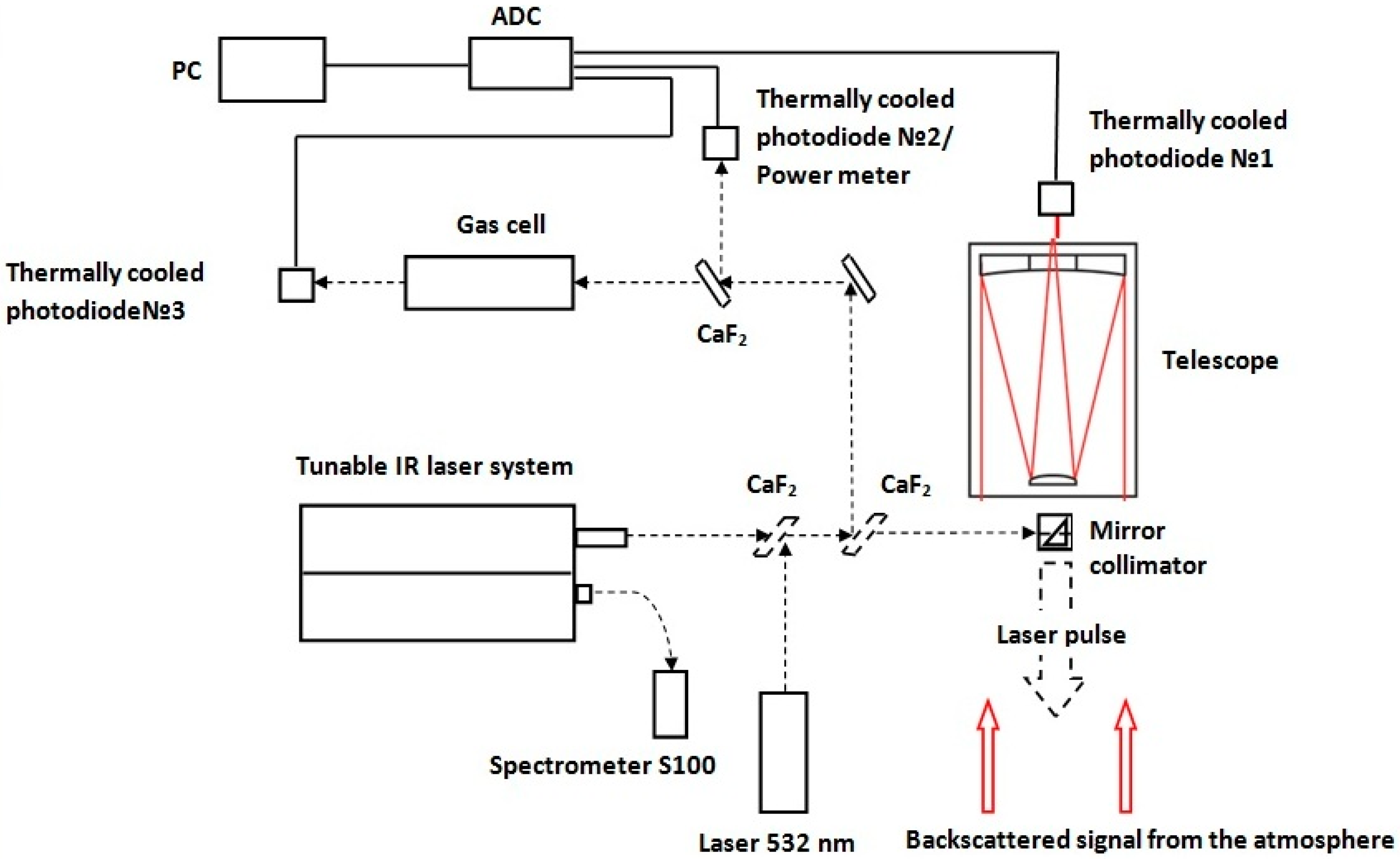
The universal scheme of the OPO lidar system developed (Figure 1) is used in field atmospheric measurements. During the measurements in the atmosphere, a part of laser radiation reflected by CaF2 plate is used to measure the transmitted pulse energy in the experimental setup. A visible laser at 532 nm is used to align the invisible IR radiation to maintain the trans-receiver axes. Further, the wavelength of the laser radiation is measured using spectrometer S100 as shown in Figure 1. Photodetector records a backscattered signal from the atmosphere collected by the receiving telescope Cassegrain.
3.2. Laser Source
The laser system [28] (SOLAR LS, Minsk, Russia) consists of the LQ529B pumping laser and KTA/KTP radiation converter which operates in the IR region; it provides tunable generation of nanosecond radiation pulses in the spectral ranges 1.4–1.6, 1.8–2.6, and 3–4 µm. In this work spectral radiation of the laser source from 3.30 to 3.50 µm is used. The main parameters of the laser source are given in Table 1. The appearance of the master oscillator and the radiation conversion unit are shown in Figure 2. The laser system is described in more detail in [24,28,29].
3.3. Collimator Mirrors
3.4. Receiving Telescope
A Cassegrain telescope developed at the IAO SB RAS was used as a receiver optics to collect the backscattered signal from the atmosphere. The coating material of the telescope mirrors allows operation in the entire lasing range of the laser. Table 3 presents the telescope specification.
When the telescope is included in the scheme of experimental setup, a direct connection to the spectral selection equipment is assumed. Figure 3 shows a receiving telescope and a mirror collimator.
3.5. Photodetectors
Lidar signals are detected using thermally cooled IBSG photo diode (IBSG, St.Petersburg, Russia) [31], PD36-03-TEC-PRW with AMT-07M amplifier. Characteristics of photo detector are presented in Table 4.
The power of the laser source is measured with the use of Ophir Nova II, Vega, and Thorlabs PM100USB power and energy meters with PE10-C, PE25-C, PE25BB, and ES120C measuring heads, respectively.
3.6. Data Acquisition Device
The data acquisition is provided by Rigol 1104Z-S and Acute TS2202E oscilloscopes. A Rigol 1104Z-S oscilloscope is a classic device which supports the NI-VISA software interface [32] and a capability of connecting the device to a notebook via USB and Ethernet interfaces. Acute TS2202E is a compact USB device with a possibility of expanding the number of input channels via the connection to six identical devices (12 analog inputs). Characteristics of the devices are given in Table 5.
The acquisition of experimental data is automated by software which combines individual functional units of the setup into a single system.
3.7. Calibration of the Lidar System
To calibrate the lidar system and measure the absorption coefficients at the selected informative sounding wavelengths, the scheme in Figure 1 was used. A calibration gas cell to the scheme was added. The optical scheme of the experiments is shown in Figure 4.
A series of laboratory experiments on measurements of the laser radiation absorption by methane in a molecular mixture was carried out. The 3.30–3.50 μm spectral range (pairs of on and off sounding wavelengths [33]) was selected for the experiments. It contains a quite strong methane absorption band. A CH4:N2 (2:98) molecular mixture in a cell at a pressure of 1 atm was used.
The laser system radiation is guided to KG-01 gas cell (100 mm long; the diameter of the CaF2window is 40 mm) by plane-parallel CaF2 plates and a rotating mirror. Before propagating through the gas cell, a part of the radiation is directed onto the thermally cooled photodiode No. 2 because of the reflection from the CaF2 plate (division ratio is 50/50) and a reference signal is thus recorded. Thermally cooled photodiode No. 3 measures an informative signal at the gas cell exit. The gas mixture transmission spectra are calculated from the ratio of the reference to informative signals. The coefficient of OPO laser radiation absorption by the molecular mixture in the gas cell is calculated by the Lambert–Beer law.
Mirror collimator and receiving telescope within the scheme allow recording backscattered radiation from the atmosphere and, at the same time, using the cell as a calibration component during full-scale measurements. The complete methodology for atmospheric measurements in Section 3.1 is described.
Table 6 shows the OPO laser radiation absorption coefficients in the calibrated CH4:N2 (2:98) gas mixture at a pressure of 1 atm in the wavelength range 3.30–3.50 μm [33], calculated based on HITRAN database [34] and experimentally measured. In this spectral range, the tuning was made to more than 60 wavelengths of the OPO laser, including both informative and uninformative wavelengths for methane sounding. The information about the latter is useful for the calibration of the OPO lidar system.
Experiments to identify the absorption lines of methane in the spectral region from 3.3460 μm to 3.4790 μm were carried out. The absorption coefficients using these experimental data were calculated. Further, these lines have been validated by analyzing the HITRAN database. Based on our analysis, laser probing wavelengths at 3.4157 μm and 3.4177 μm as online and offline wavelength for methane measurements in the atmosphere were chosen.
The discrepancy of the absorption coefficients in the spectral regions that are not informative for gas analysis can be due to the influence of interfering absorption by external gases. The absorption coefficients measured (by the laser pulse energy after the absorbing cell) are in a good agreement with the absorption coefficients calculated using the HITRAN database at the sounding-informative wavelengths.
4. Measurement Results and Discussion
To test the capabilities the lidar system developed for methane sounding, the tuning range was reduced to informative for the gas under study (the measurements have been carried out in the 3.30–3.50 μm spectral range, which includes a quite strong absorption band of methane).
Figure 5 and Figure 6 shows the experimental design, the main components of the OPO lidar system and experimental geometry during full-scale measurements in the atmosphere.
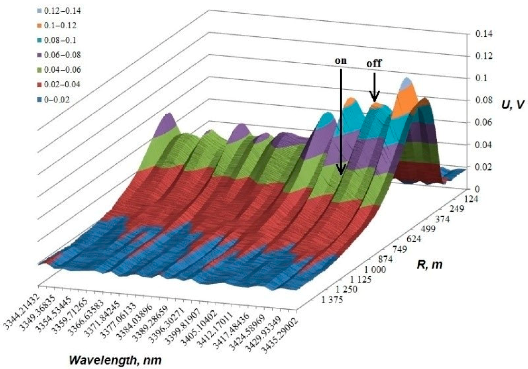
Figure 7 shows the tuning curve of the atmospheric response, the spectral range of which includes informative methane absorption lines, for example, 3.39 μm (U is the voltage of the backscattered signal at the photodiode detector, V; R is the atmospheric path, m).
Using the IR OPO lidar system (see Figure 5), the distribution of CH4 concentrations were experimentally studied from sounding at the pair of wavelengths 3415.711 (on-line) and 3417.484 nm (off-line) [33] with a spatial resolution of 100 m in urban environment. The measurements were carried out in Tomsk on 1 February 2019.
Figure 8 exemplifies oscillograms of lidar signals recorded during the in situ measurements (axis X—pulse length, µs; axis Y—U is the voltage of the backscattered signal at the photodiode detector, V).
Figure 9 shows the lidar signal measured under the wavelength tuning in the spectral range 3.30–3.43 µm (alternate accumulation of signals at informative wavelengths at discrete sets of lidar radiation lines was performed; the switching time between the wavelengths was 35–50 ms and the averaging time was 6.4 s).
The results of experimental measurements of the CH4 concentration distribution along a 800 m sounding path with the OPO lidar system are shown in Figure 10.
The background concentration of methane was calculated using the equation shown in Equation (2). The path averaged methane concentration of about 2.085 ppm over the path length of 800 m was retrieved. The measurement results were compared (Figure 10b) with the data from the TOR (tropospheric ozone research) station of the IAO SB RAS [35,36], where the methane concentration is around-the-clock measured. The OPO lidar and the TOR station are located in the same building. The error level of methane concentration recovery correspond to 8–13% relative to the averaged value.
5. Conclusions
The IR OPO lidar system has been designed. The technical characteristics of the main units of the IR OPO lidar system are given. It allows the reception and processing of backscattered signals in the IR spectral region along the surface tropospheric paths. The experimental results show applicability of the IR OPO lidar system to study the distribution of methane concentration (~2.085 ppm) at 800 m atmospheric path with a spatial resolution of 100 m in the mid-IR. The error level of methane concentration recovery correspond to 8–13% relative to the averaged value. The lidar methane measurements are in a good agreement with the data of the TOR station.
The results of this work confirm the applicability of the OPO lidar system designed to the study and control the distribution of CH4 concentration in the surface air layer, and to retrieve CH4 concentration close to background or near-background values.
Author Contributions
Conceptualization, S.Y., S.S., and O.K.; methodology, S.Y., S.S., and O.K.; validation, S.S. and N.K.; data curation, S.S. and O.K.; writing—original draft preparation, S.Y.; writing—review and editing, S.Y.; visualization, S.S. and N.K.; supervision, S.Y.; project administration, S.Y. All authors have read and agreed to the published version of the manuscript.
Funding
This research was funded by the Russian Foundation for Basic Research (grant no. 19-45-700003) and the President of the Russian Federation (grant no. MK-932.2019.8 for support of young Russian scientists).
Conflicts of Interest
The authors declare no conflict of interest.
References
- Reghunath, A.T.; Malhotra, P.; Kumar, Y.; Bhushan, B. Design of a tunable mid-IR OPO source for DIAL detection of trace gases. In Proceedings of the Asia-Pacific Remote Sensing Symposium, Goa, India, 13–17 November 2006; Volume 6409, p. 64091B. [Google Scholar] [CrossRef]
- Douglass, K.O.; Maxwell, S.E.; Plusquellic, D.F.; Hodges, J.T.; Van Zee, R.D.; Samarov, D.V.; Whetstone, J.R. Construction of a high power OPO laser system for differential absorption LIDAR. In Lidar Remote Sensing for Environmental Monitoring XII; SPIE International Society for Optics and Photonics: Bellingham, WA, USA, 2011; Volume 8159, p. 81590D. [Google Scholar] [CrossRef]
- Barrientos-Barria, J.; Dherbecourt, J.; Raybaut, M.; Godard, A.; Melkonian, J.M.; Lefebvre, M.H.; Faure, B.; Souhaite, G. 3.3–3.7 μm Nested cavity OPO pumped by an amplified micro-laser for portable DIAL. In Proceedings of the Conference on Lasers & Electro-Optics Europe & International Quantum Electronics Conference, Munich, Germany, 12–16 May 2013; IEEE: Piscataway, NJ, USA, 2013. [Google Scholar]
- Amoruso, S.; Amodeo, A.; Armenante, M.; Boselli, A.; Mona, L.; Pandolfi, M.; Pappalardo, P.; Velotta, R.; Spinelli, N.; Wang, X. Development of a tunable IR lidar system. Opt. Lasers Eng. 2002, 37, 521–532. [Google Scholar] [CrossRef] [Green Version]
- Ayrapetyan, V.S. Measurement of absorption spectra for atmospheric methane by a lidar system with tunable emission wavelength in the range 1.41–4.24 μm. J. Appl. Spectrosc. 2009, 76, 268–272. [Google Scholar] [CrossRef]
- Amediek, A.; Fix, A.; Wirth, M.; Ehret, G. Development of an OPO system at 1.57 μm for integrated path DIAL measurement of atmospheric carbon dioxide. Appl. Phys. B 2008, 92, 295–302. [Google Scholar] [CrossRef] [Green Version]
- Barrientos-Barria, J.; Alexandre Dobroc, A.; Coudert-Alteirac, H.; Raybaut, M.; Cezard, N.; Dherbecourt, J.-P.; Faure, B.; Souhaité, G.; Melkonian, J.-M.; Godard, A.; et al. 3.3–3.7 μm OPO/OPA optical source for multi-species 200 m range Integrated Path DIfferential Absorption Lidar. In Applications of Lasers for Sensing and Free Space Communications; Optical Society of America: Washington, WA, USA, 2013; p. LTh1B-4. [Google Scholar]
- Mammez, D.; Cadiou, E.; Dherbecourt, J.-P.; Raybaut, M.; Melkonian, J.-M.; Godard, A.; Gorju, G.; Pelon, J.; Lefebvre, M. Multispecies transmitter for DIAL sensing of atmospheric water vapour, methane and carbon dioxide in the 2 μm region. In Lidar Technologies, Techniques, and Measurements for Atmospheric Remote Sensing XI; International Society for Optics and Photonics: Bellingham, WA, USA, 2015; Volume 9645, p. 964507. [Google Scholar] [CrossRef]
- Robinson, I.; Jack, J.W.; Rae, C.F.; Moncrieff, J.B. Development of a laser for differential absorption lidar measurement of atmospheric carbon dioxide. In Lidar Technologies, Techniques, and Measurements for Atmospheric Remote Sensing X; International Society for Optics and Photonics: Bellingham, WA, USA, 2014; Volume 9246, p. 92460U. [Google Scholar] [CrossRef] [Green Version]
- Robinson, I.; Jack, J.W.; Rae, C.F.; Moncrieff, J.B. A robust optical parametric oscillator and receiver telescope for differential absorption lidar of greenhouse gases. In Lidar Technologies, Techniques, and Measurements for Atmospheric Remote Sensing XI; International Society for Optics and Photonics: Bellingham, WA, USA, 2015; Volume 9645, p. 96450U. [Google Scholar] [CrossRef] [Green Version]
- Mitev, V.; Borelli, R.; Fiorani, L.; Grigorov, I.; Nuvoli, M.; Palucci, A.; Pistilli, M.; Puiu, A.; Rebane, O.; Santoro, S. Lidar extinction measurement in the mid infrared. In Proceedings of the 20th International Symposium on Atmospheric and Ocean Optics: Atmospheric Physics, Novosibirsk, Russian, 2014; International Society for Optics and Photonics: Bellingham, WA, USA, 2014; Volume 9292, p. 92923W. [Google Scholar] [CrossRef]
- Geiger, A.R. Mid-Infrared Light Hydrocarbon Dial Lidar. U.S. Patent 5,157,257, 20 October 1992. [Google Scholar]
- Kalayeh, H.M. Multi-Sensors and Differential Absorption LIDAR Data Fusion. U.S. Patent 7,411,196, 12 August 2008. [Google Scholar]
- Lippert, J.L.; Stearns, S.V.; Brake, D.E.; Fisher, C.M. Gas Flux Determination Using Airborne DIAL LIDAR and Airborne Wind Measurement. U.S. Patent 8,121,798, 21 February 2012. [Google Scholar]
- Liu, J. Method and Apparatus for Wavelength Locking Free Optical Frequency Comb Based Differential Absorption Lidar. U.S. Patent 8,541,744, 24 September 2013. [Google Scholar]
- DeAntonio, M.; Motto, R. Variable-Wavelength Lidar System. U.S. Patent Application 14/101,143, 12 June 2014. [Google Scholar]
- Foltynowicz, R. High-energy, Broadband, Rapid Tuning Frequency Converter. U.S. Patent 8,837,538, 16 September 2014. [Google Scholar]
- Ayrapetyan, V.S.; Fomin, P.A. Laser detection of explosives based on differential absorption and scattering. Opt. Laser Technol. 2018, 106, 202–208. [Google Scholar] [CrossRef]
- Weidmann, D. Heterodyne Detection System and Method. U.S. Patent 9,366,622, 14 June 2016. [Google Scholar]
- Mitev, V.; Babichenko, S.; Bennes, J.; Borelli, R.; Dolfi-Bouteyre, A.; Fiorani, L.; Hespel, L.; Huet, T.; Palucci, A.; Pistilli, M.; et al. Mid-IR DIAL for high-resolution mapping of explosive precursors. In Lidar Technologies, Techniques, and Measurements for Atmospheric Remote Sensing IX; International Society for Optics and Photonics: Bellingham, WA, USA, 2013; Volume 8894, p. 88940S. [Google Scholar] [CrossRef]
- Cadiou, E.; Mammez, D.; Dherbecourt, J.-B.; Gorju, G.; Pelon, J.; Melkonian, J.-M.; Godard, A.; Raybaut, M. Atmospheric boundary layer CO2 remote sensing with a direct detection LIDAR instrument based on a widely tunable optical parametric source. Opt. Lett. 2017, 42, 4044–4047. [Google Scholar] [CrossRef] [PubMed]
- Shibata, Y.; Nagasawa, C.; Abo, M. Development of 1.6 μm DIAL using an OPG/OPA transmitter for measuring atmospheric CO2 concentration profiles. Appl. Opt. 2017, 56, 1194–1201. [Google Scholar] [CrossRef] [PubMed]
- Veerabuthiran, S.; Razdan, A.K.; Jindal, M.K.; Sharma, R.K.; Sagar, V. Development of 3.0–3.45 nm OPO laser based range resolved and hard-target differential absorption lidar for sensing of atmospheric methane. Opt. Laser Technol. 2015, 73, 1–5. [Google Scholar] [CrossRef]
- Romanovskii, O.A.; Sadovnikov, S.A.; Kharchenko, O.V.; Yakovlev, S.V. Development of Near/Mid IR differential absorption OPO lidar system for sensing of atmospheric gases. Opt. Laser Technol. 2019, 116, 43–47. [Google Scholar] [CrossRef]
- Collis, R.T.H.; Russell, P.B. Lidar Measurement of Particles and Gases by Elastic Backscattering and Differential Absorption. In Laser Monitoring of the Atmosphere; Hinkley, E.D., Ed.; Springer: New York, NY, USA, 1976; pp. 91–180. [Google Scholar]
- Romanovskii, O.A.; Kharchenko, O.V.; Yakovlev, S.V. Methodical Aspects of Lidar Sensing of Trace Gases in Atmosphere by Differential Absorption Method. J. Appl. Spectrosc. 2012, 79, 799–806. [Google Scholar] [CrossRef]
- Matvienko, G.G.; Romanovskii, O.A.; Sadovnikov, S.A.; Sukhanov, A.Y.; Kharchenko, O.V.; Yakovlev, S.V. Study of the possibility of using a parametric-light-generator-based laser system for lidar probing of the composition of the atmosphere. J. Opt. Technol. 2017, 84, 408–414. [Google Scholar] [CrossRef]
- SOLAR LS. Available online: https://solarlaser.com/en (accessed on 10 January 2019).
- Romanovskii, O.A.; Kharchenko, O.V.; Kondratyuk, N.V.; Protasenya, A.L.; Shumskii, V.K.; Sadovnikov, S.A.; Yakovlev, S.V. OPO-laser system for atmospheric sounding in the mid-IR range. In 21st International Symposium Atmospheric and Ocean Optics: Atmospheric Physics; International Society for Optics and Photonics: Bellingham, WA, USA, 2015; Volume 9680, p. 96803V. [Google Scholar] [CrossRef]
- THORLABS. Available online: https://www.thorlabs.com (accessed on 10 January 2019).
- IBSG Co., Ltd. Available online: http://www.ibsg-st-petersburg.com/phd.html (accessed on 10 January 2019).
- National Instruments VISA. Available online: https://www.ni.com/visa (accessed on 10 January 2019).
- Romanovskii, O.A.; Sadovnikov, S.A.; Kharchenko, O.V.; Yakovlev, S.V. Broadband IR lidar for gas analysis of the atmosphere. J. Appl. Spectrosc. 2018, 85, 457–461. [Google Scholar] [CrossRef]
- Gordon, I.E.; Rothman, L.S.; Hill, C.; Kochanov, R.V.; Tan, Y.; Bernath, P.F.; Birk, M.; Boudon, V.; Campargue, A.; Chance, K.V.; et al. The HITRAN2016 Molecular Spectroscopic Database. J. Quant. Spectrosc. Radiat. Transf. 2017, 203, 3–69. [Google Scholar] [CrossRef]
- Davydov, D.K.; Belan, B.D.; Antokhin, P.N.; Antokhina, O.Y.; Antonovich, V.V.; Arshinova, V.G.; Arshinov, M.Y.; Akhlestin, A.Y.; Belan, S.B.; Dudorova, N.V.; et al. Monitoring of Atmospheric Parameters: 25 Years of the Tropospheric Ozone Research Station of the Institute of Atmospheric Optics, Siberian Branch, Russian Academy of Sciences. Atmos. Ocean. Opt. 2019, 32, 180–192. [Google Scholar] [CrossRef]
- TOR (Tropospheric Ozone Research) Station. Available online: http://lop.iao.ru/EN/ (accessed on 1 February 2019).
Figure 1.
Infrared optical parametric oscillators (IR OPO) lidar system optical scheme.

Figure 2.
Laser system [28].
Figure 2.
Laser system [28].

Figure 3.
Cassegrain receiving telescope and mirror collimator.

Figure 4.
Calibration scheme of the IR OPO lidar system.

Figure 5.
Tunable IR laser system and laser radiation direction.

Figure 6.
Experimental geometry.

Figure 7.
Tuning range for atmospheric response in the 3298–3498-nm range (amplificationn factor is equal to 1 (a) and 10 (b)).
Figure 7.
Tuning range for atmospheric response in the 3298–3498-nm range (amplificationn factor is equal to 1 (a) and 10 (b)).

Figure 8.
Oscillograms of lidar signals recorded during the atmospheric measurements at a wavelength of (a) 3415.711 nm (on-line CH4) and (b) 3417.484 nm (off-line CH4).
Figure 8.
Oscillograms of lidar signals recorded during the atmospheric measurements at a wavelength of (a) 3415.711 nm (on-line CH4) and (b) 3417.484 nm (off-line CH4).

Figure 9.
Lidar signal recorded under wavelength tuning in the region of OPO laser radiation absorption by CH4.
Figure 9.
Lidar signal recorded under wavelength tuning in the region of OPO laser radiation absorption by CH4.

Figure 10.
CH4 concentration measured along a 800-m surface atmospheric path with a spatial resolution of 100 m (a) and at the tropospheric ozone research (TOR) station of IAO SB RAS (b).
Figure 10.
CH4 concentration measured along a 800-m surface atmospheric path with a spatial resolution of 100 m (a) and at the tropospheric ozone research (TOR) station of IAO SB RAS (b).


Table 1.
Laser source parameters.
| Parameter | Value |
|---|---|
| Pulse energy, mJ | 6 |
| Pulse frequency, Hz | 10 |
| Pulse length, ns | 10–13 |
| Spectral linewidth, cm−1 | 1 |
| Wavelength tuning control | with 3 step motors |
| Radiation divergence, µrad | 200 |
Table 2.
Parameters of collimator mirrors.
| Parameter | Values | |
|---|---|---|
| Model | MPD00M9-P01 | MPD269-P01 |
| Surface material | Aluminum | |
| Reflectivity | >96% (λ = 2–20 μm) | |
| Diameter | 12.7 mm (1/2″) | 50.8 mm (2″) |
| Focal length | 15.0 mm (0.59″) | 152.4 mm (6″) |
| Off-axis angle | 90° | 90° |
| Wavefront distortion | <λ/4 at 633 nm | <λ/4 at 633 nm |
Table 3.
Receiving telescope specification.
| Parameter | Values |
|---|---|
| Optical scheme | Cassegrain |
| Primary mirror diameter, mm | 300 |
| Effective focal length, mm | 1457 |
| Field of view, ° | 0.0117 |
| Relative aperture | 1:4.85 |
| Aberration circle diameter, μm | 70 |
Table 4.
Main parameters of photodiode.
| Parameter | Values |
|---|---|
| Model | PD36-03 |
| Material | InAs/InAsSbP |
| Spectral range, μm | 1.5–3.8 |
| Peak sensitivity wavelength, μm | 2.6–3.4 |
| Detectivity, cm·Hz1/2·W−1 | (3–6) × 109 |
| Current monochromatic sensititvity, A/W | 1.0–1.2 |
| Rise time, ns | 20–120 |
| Active area diameter, mm | 0.3 |
Table 5.
Oscillograph specification.
| Parameter | Values | |
|---|---|---|
| Model | Rigol 1104Z-S | Acute TS2202E |
| Number of analog inputs | 4 | 2 |
| Transmission band, MHz | 100 | 200 |
| Resolution, bit | 12 | 8 |
| Sampling frequency over all channels, Gsample/s | 1 | 1 |
Table 6.
The comparison of absorption coefficients in the spectral region of 3.346–3.479 μm.
| Wavelength, μm | KCH4:N2, cm−1 | KCH4:N2, cm−1 |
|---|---|---|
| (Air) | (Experiment) | (Calculation) |
| 3.3460 | 0.011 | 0.011 |
| 3.3579 | 0.008 | 0.005 |
| 3.3668 | 0.017 | 0.021 |
| 3.3895 | 0.009 | 0.012 |
| 3.4018 | 0.015 | 0.017 |
| 3.4157 | 0.019 | 0.020 |
| 3.4177 | 0.005 | 0.002 |
| 3.4536 | 0.007 | 0.004 |
| 3.4790 | 0.000 | 0.001 |
© 2020 by the authors. Licensee MDPI, Basel, Switzerland. This article is an open access article distributed under the terms and conditions of the Creative Commons Attribution (CC BY) license (http://creativecommons.org/licenses/by/4.0/).
Share and Cite
MDPI and ACS Style
Yakovlev, S.; Sadovnikov, S.; Kharchenko, O.; Kravtsova, N. Remote Sensing of Atmospheric Methane with IR OPO Lidar System. Atmosphere 2020, 11, 70. https://doi.org/10.3390/atmos11010070
AMA Style
Yakovlev S, Sadovnikov S, Kharchenko O, Kravtsova N. Remote Sensing of Atmospheric Methane with IR OPO Lidar System. Atmosphere. 2020; 11(1):70. https://doi.org/10.3390/atmos11010070
Chicago/Turabian StyleYakovlev, Semyon, Sergey Sadovnikov, Olga Kharchenko, and Natalya Kravtsova. 2020. "Remote Sensing of Atmospheric Methane with IR OPO Lidar System" Atmosphere 11, no. 1: 70. https://doi.org/10.3390/atmos11010070
Note that from the first issue of 2016, this journal uses article numbers instead of page numbers. See further details here.