Article

Innovative Strategies for Observations in the Arctic Atmospheric Boundary Layer (ISOBAR)—The Hailuoto 2017 Campaign

by Stephan T. Kral 1,2,*, Joachim Reuder 1, Timo Vihma 2, Irene Suomi 2, Ewan O’Connor 2, Rostislav Kouznetsov 2,3, Burkhard Wrenger 4, Alexander Rautenberg 5, Gabin Urbancic 1,2, Marius O. Jonassen 1,6, Line Båserud 1, Björn Maronga 1,7, Stephanie Mayer 8, Torge Lorenz 8, Albert A. M. Holtslag 9, Gert-Jan Steeneveld 9, Andrew Seidl 1, Martin Müller 10, Christian Lindenberg 10, Carsten Langohr 4, Hendrik Voss 4, Jens Bange 5, Marie Hundhausen 5, Philipp Hilsheimer 5 and Markus Schygulla 5add Show full author list remove Hide full author list
1
Geophysical Institute and Bjerknes Centre for Climate Research, University of Bergen, Postbox 7803, 5020 Bergen, Norway
2
Finnish Meteorological Institute, P.O. Box 503, 00101 Helsinki, Finland
3
A.M. Obukhov Institute for Atmospheric Physics, RU-119017 Moscow, Russia
4
Department of Environmental Engineering and Computer Science, University of Applied Sciences Ostwestfalen-Lippe, An der Wilhelmshöhe 44, 37671 Höxter, Germany
5
Department of Geosciences, University of Tübingen, Hölderlinstr. 12, 72074 Tübingen, Germany
6
The University Centre in Svalbard, P.O. Box 156, N-9171 Longyearbyen, Norway
7
Institute of Meteorology and Climatology, Leibniz University Hannover, P.O. Box 6009, D-30060 Hannover, Germany
8
Uni Research Climate, Bjerknes Centre for Climate Research, P.O. Box 7810, N-5020 Bergen, Norway
9
Meteorology and Air Quality Section, Wageningen University, P.O. Box 9101, NL-6700 HB Wageningen, The Netherlands
10
Lindenberg und Müller GmbH & Co. KG, Fasanenweg 4, 31249 Hohenhameln, Germany
*
Author to whom correspondence should be addressed.
Atmosphere 2018, 9(7), 268; https://doi.org/10.3390/atmos9070268
Submission received: 30 April 2018 / Revised: 30 June 2018 / Accepted: 11 July 2018 / Published: 16 July 2018
(This article belongs to the Special Issue Atmospheric Measurements with Unmanned Aerial Systems (UAS))

Abstract

:
The aim of the research project “Innovative Strategies for Observations in the Arctic Atmospheric Boundary Layer (ISOBAR)” is to substantially increase the understanding of the stable atmospheric boundary layer (SBL) through a combination of well-established and innovative observation methods as well as by models of different complexity. During three weeks in February 2017, a first field campaign was carried out over the sea ice of the Bothnian Bay in the vicinity of the Finnish island of Hailuoto. Observations were based on ground-based eddy-covariance (EC), automatic weather stations (AWS) and remote-sensing instrumentation as well as more than 150 flight missions by several different Unmanned Aerial Vehicles (UAVs) during mostly stable and very stable boundary layer conditions. The structure of the atmospheric boundary layer (ABL) and above could be resolved at a very high vertical resolution, especially close to the ground, by combining surface-based measurements with UAV observations, i.e., multicopter and fixed-wing profiles up to 200 m agl and 1800 m agl, respectively. Repeated multicopter profiles provided detailed information on the evolution of the SBL, in addition to the continuous SODAR and LIDAR wind measurements. The paper describes the campaign and the potential of the collected data set for future SBL research and focuses on both the UAV operations and the benefits of complementing established measurement methods by UAV measurements to enable SBL observations at an unprecedented spatial and temporal resolution.

1. Introduction

The atmospheric boundary layer (ABL) is the lowest part of the atmosphere where the Earth’s surface strongly influences the wind, temperature, and humidity through turbulent transport of air mass. Due to its superior importance for the atmosphere system, an appropriate representation of the ABL is essential for both operational numerical weather prediction (NWP) and climate models as well as for a wide range of practical applications, such as air pollution forecast and wind energy yield estimates. In contrast to the ABL, the stable boundary layer (SBL) is typically one order of magnitude shallower and can reach a vertical extent as low as 10 m . Turbulence in the SBL is typically much weaker or intermittent and is mainly produced by vertical wind shear, whereas buoyancy inhibits vertical motion. Furthermore, a number of nonturbulent motions, such as wave-like motions, solitary modes, microfronts or drainage flows, become important [1]. The principal problem in representing turbulence in those models correctly is that the length scales of the turbulent processes are typically far below model resolution and therefore need to be parameterized. While the corresponding parameterization schemes, e.g., reference [2], generally work very well for near-neutral and unstable conditions, they show significant shortcomings for the SBL, e.g., by systematically overestimating turbulent mixing rates and the height of the ABL ( h A B L ) [3,4,5,6]. In the context of weather forecasting, this leads to, amongst others, significant errors in the prediction of near surface parameters, such as the 2-m temperature and 10-m wind speed for situations with clear skies and low wind typically occurring at night or during winter [6]. Errors in h A B L might also induce considerable uncertainties in the forecast of wind profiles and the location of low-level jets (LLJ), which are crucial parameters for applications such as wind energy. Furthermore, this also leads to a typical warm bias for SBL conditions in NWP models [4,7,8], which is also of importance under the aspects of climate and climate change. One of the most dominant signals in climate records is the accelerated warming of the polar regions during wintertime and the increase in nighttime temperatures at lower latitudes [9]. This observed polar amplification may be partly related to the shallow SBL with a corresponding small heat capacity. Hence, a certain heat gain results in a relatively large temperature increase [10]. In addition, this dampens the temperature inversion infrared cooling to space [11,12]. A systematic overestimation of turbulent mixing and the ABL height thus complicates the proper attribution of the mechanisms of Arctic climate change [12,13,14].
Monin–Obukhov similarity theory (MOST) provides dimensionless relationships between the surface fluxes of heat and momentum, the variance and the mean gradients of temperature, moisture, and wind in the atmospheric surface layer (SL). These dimensionless relationships are a function of the height (z) above the surface, which is made dimensionless with the Monin–Obukhov length scale (L). Strictly speaking, these relationships apply only for stationary and homogeneous surface conditions. In practice, however, there is a strong need for wider application, and as such, field observations in a variety of circumstances are needed to evaluate the dimensionless relationships. Most of the surface parameterization schemes in NWP and climate models are based on the traditional MOST, which is known for its shortcomings in characterizing the SBL [15,16,17,18,19,20,21]. Under such conditions, continuous turbulence may break down and become intermittent e.g., [22], so that non-local features, such as the stability at higher levels and the Coriolis effect, gain relative importance [23,24]. This may imply the occurrence of upside-down events, in which turbulence is mainly generated by the vertical wind shear associated with LLJ [23,25]. Additional processes, such as inertial oscillations and gravity waves [26] can then contribute significantly to the turbulent kinetic energy (TKE) budget. Zilitinkevich and Calanca [15] and Zilitinkevich [27] presented an attempt for a non-local theory for the SBL, taking into account the effect of internal gravity waves in the free atmosphere. In addition, other small-scale processes and phenomena, such as drainage flow, radiation divergence [1,6,28], fog, and close interactions with the surface as well as potential snow feedback [29] further increase the complexity of the SBL. The effects of all those phenomena are neither well understood, nor sufficiently captured by MOST or its extensions [15,30,31,32].
SBL conditions also impose challenges with respect to observations, as the typically weak turbulent fluxes close to the surface become difficult to measure precisely under very stable conditions. Gradient-based scaling schemes, as proposed by [20,33,34] and formally equivalent to the MOST approach, might overcome some of the observational issues of weak turbulent fluxes, since the vertical gradients within the SBL are usually strong and relatively easy to measure. From a modeling point of view, recent high-resolution large-eddy simulation (LES) studies have shown a lack of grid convergence under stable conditions [35,36,37] which might be attributed to the fact that MOST is usually applied between the surface and the first grid level in the atmosphere (i.e., typically at heights between 1 m to 10 m ). This might violate basic assumptions for MOST, e.g., that the measurement level or the first grid level in LES cases must lie inside the inertial sublayer, in which the flow is spatially homogeneous and dissipation follows Kolmogorov’s 5/3 law. Errors can be induced by the fact that turbulence is not properly resolved at the first couple of grid points adjacent to the surface. In such cases, turbulence is not fully resolved and the flow is dominated by the subgrid-scale model in use. It is often observed that this general deficiency of LES models to resolve turbulence near the surface leads to near-surface gradients that are too strong and inherently lead to an underestimation of the surface friction [38].
Field campaigns addressing the SBL generally face logistical challenges in taking measurements at remote sites that are difficult to reach and are often characterized by harsh weather conditions, especially in regard to low temperatures. In particular, observations over sea ice involve additional risks for equipment and people, e.g., due to sea ice motion and melt. Major campaigns with focus on the SBL over sea ice have included the Weddell ice station in the Austral autumn and winter of 1992 [39,40,41,42], the Surface Heat Budget over the Arctic Ocean (SHEBA) in the Beaufort Sea in 1997–1998 [23,43,44], the drifting ice station, Tara, in the central Arctic in the spring and summer of 2007 [45,46,47], and the drifting station, N-ICE2015, north of Svalbard in the winter and spring of 2015 [48]. Other land-based campaigns, e.g., ARTIST [49], CASES-99 [50], GABLS [51,52], FLOSS-II [53], the measurements at Summit Station in central Greenland [54], and recently, MATERHORN [55] have also contributed considerably to the current state of knowledge on SBLs. The typical observation methods applied in such campaigns are profile measurements using weather masts, tethersondes, and radiosondes, as well as eddy covariance (EC) measurements at one or multiple levels. Several SBL studies have also been based on manned research aircraft observations, mainly over sea ice in the Arctic [56,57,58,59,60] and the Baltic Sea [61,62]. Manned research aircraft may also release dropsondes and apply airborne LIDARs [63]. Over the last decade, the use of Unmanned Aerial Vehicles (UAVs) has also rapidly increased in the field of atmospheric research [64,65] and corresponding systems have been applied in ABL campaigns, both in the Arctic [66,67,68] and Antarctic [69,70,71,72,73].
The different methods for observing the SBL are generally complementary. Continuous time series of basic meteorological parameters at different temporal resolutions can be obtained in-situ by weather masts, tethersondes, or radiosonde ascents, or they can be remotely sensed by e.g., with LIDAR (Light Detection and Ranging), SODAR (Sound Detection and Ranging), RADAR (Radio Detection and Ranging), RASS (Radar-Acoustic Sounding System) or microwave radiometer observations. All these measurement methods and devices have certain shortcomings that may be at least partially overcome by proper UAV missions. Weather masts are limited in height and are rather inflexible with respect to changes in location. Tethersondes require considerable infrastructure and their operation is limited to wind speeds below 12 m   s −1 [47]. Continuous data are only available if the balloon is kept at a fixed altitude, which limits the vertical resolution [74]. In addition, sometimes the temperature inversions can be so strong that the buoyancy of the tethered balloon is not sufficient to penetrate it [67]. Rawinsonde soundings reach high altitudes, but pass very quickly through the interesting layers for SBL research. They only provide snapshots of vertical profiles in relatively poor temporal resolution, and are comparatively expensive for long-term use. Observations by large manned research aircraft are even more expensive. An additional drawback of those platforms for SBL research is the limitation in the lowermost possible flight altitude for safe operations and the fact that the pure size and velocity of the aircraft might massively disturb the local structure and dynamics of a shallow SBL. Doppler LIDARs and SODARs provide wind information with a vertical resolution in the order of 5 m to 20 m , typically in the lowest few hundred meters above the ground, depending on wind speed and stability, and, in the case of LIDAR, also on other parameters, such as the aerosol content [75], water vapor, ozone or temperature. So far, the use of remote-sensing systems for dedicated SBL campaigns in polar regions has been rather limited, [49,76,77]. Furthermore, the minimum altitude for wind information from pulsed non-scanning LIDAR systems is in the order of 40 m . Higher vertical resolution and lower minimum altitudes can be achieved by operating scanning Doppler LIDARs at low-elevation angles. However, the achieved data originates from a much larger area than for high elevation scans. Scintillometers are capable of measuring spatially-averaged turbulent fluxes and cross-winds close to the ground along horizontal paths of approximately 1 k m to 10 k m . In previous years, SBLs have also been addressed by satellite-based remote-sensing, e.g., [78].
The main motivation for the ISOBAR project is to develop and apply a new and innovative observation strategy for the SBL that is based on meteorological UAVs, ground-based in-situ, and remote-sensing profiling systems. The main idea is to combine the reliability and continuity of well-established ground-based observations with the flexibility of small UAV systems. This strategy is to be applied during several campaigns in polar regions to provide extensive data sets on the turbulent structure of the SBL with unique and unprecedented spatial and temporal resolution. This will form the basis for intensive analysis of small-scale turbulent processes in the SBL and corresponding multi-scale modeling studies.
To optimize the collection of ABL data over a period of three weeks, the Hailuoto-I campaign was based on the combined use of a weather mast, equipped for gradient and flux observations; a scanning Doppler LIDAR; a vertically pointing SODAR; and several fixed-wing and multicopter UAVs equipped with different sensors. To the authors’ knowledge, the Hailuoto-I campaign is the first field campaign to combine ground-based in-situ and remote-sensing instrumentation with the intensive use of multiple UAVs for systematic SBL research.
The manuscript is structured in the following way. In Section 2 we describe the experiment site, the instrumentation used, and some details on the operation of our UAVs. Data processing methods and data availability are summarized in Section 3. Section 4 describes the general synoptic situation and the sea ice conditions during Hailuoto-I. The first results are presented in Section 5 together with a brief discussion, before summarizing the main outcomes of the Hailuoto-I campaign and giving a short outlook on our future plans for specific analysis and modeling studies in Section 6.

2. Experiment Description

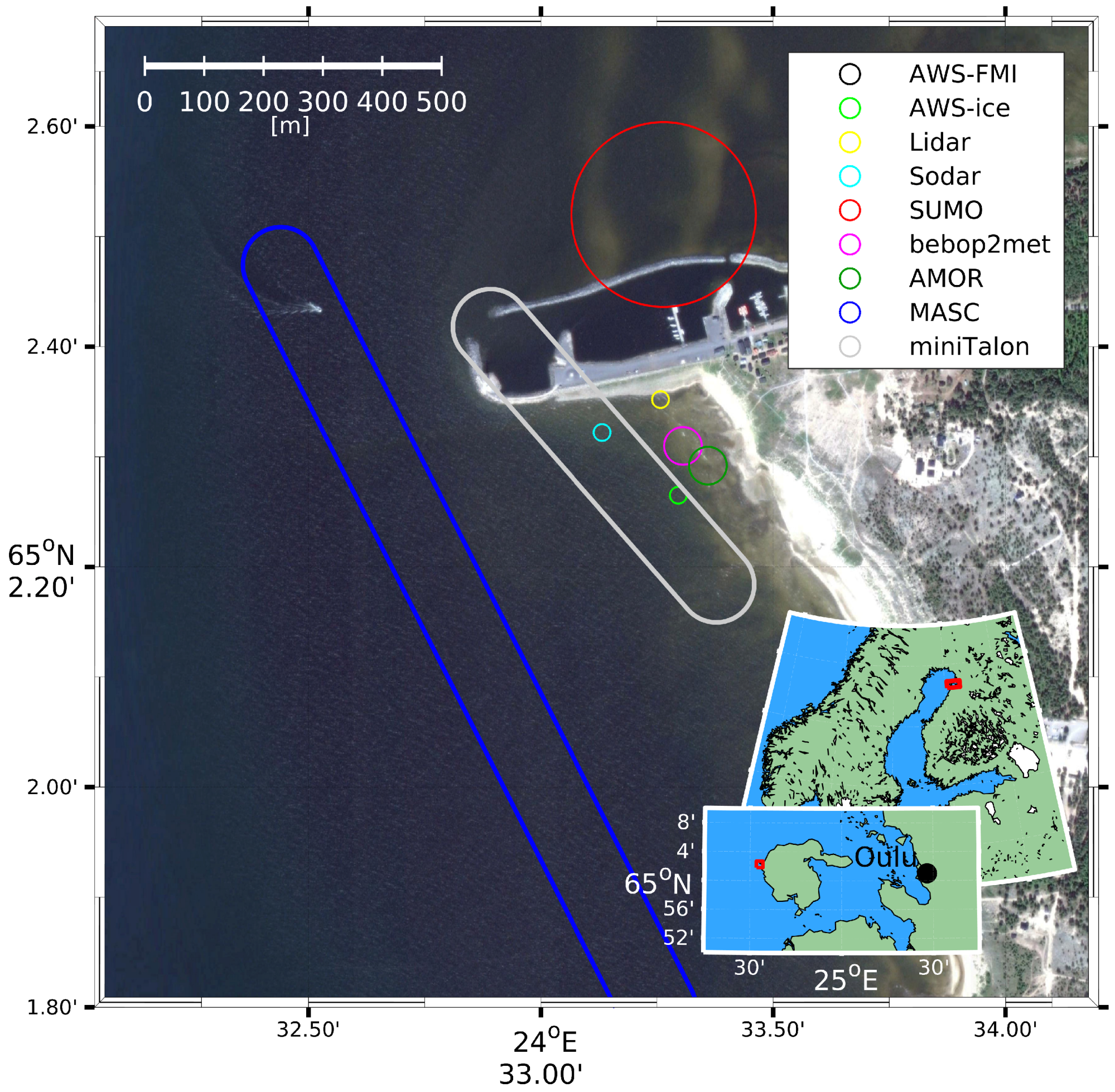
The Hailuoto-I campaign took place between 11 and 27 February 2017 over the sea ice of the Bothnian Bay, close to the Finnish island of Hailuoto, as part of the ISOBAR project. Hailuoto island is located roughly 20 k m west of the city of Oulu and has a size of about 200 k m 2 (Figure 1). Its landscape is mainly flat heath terrain, with the highest point reaching only about 20 m asl. The field site was located at 65.0384 N and 24.5549 E, just off-shore of Hailuoto Marjaniemi, the westernmost point of the island (Figure 1), where the Finnish Meteorological Institute operates a permanent weather station. Bothnian Bay, the northernmost part of the Baltic Sea, is typically entirely frozen every winter with the exception of the winters of 2014/2015 [79] and 2015/2016 with land-fast ice up to 0.8 m on the coast of Hailuoto.
During the observation period, the apparent sunrise changed from 6:35 to 5:39 UTC and the apparent sunset from 14:38 to 15:31 UTC, calculated with [80]. The noontime solar elevation angle ranged from 11.15 to 16.83 [81]. The apparent solar and sea ice conditions favored the formation of a SBL [61,62], underlying a weak diurnal cycle.
The instrumentation operated on site during the campaign included an eddy covariance (EC) system; a 4 m meteorological mast with three levels of slow-response sensors for temperature, humidity, and wind; a four component radiometer; and two ground flux sensors. The ground-based in-situ measurements were complemented by a scanning wind LIDAR, a vertically profiling SODAR, and several types of fixed and rotary-wing UAVs.

2.1. Instrumentation

2.1.1. Basic Instrumentation

Close to the selected field site, the Finnish Meteorological Institute (FMI) operates the World Meteorological Organization (WMO) automatic weather station (AWS) Hailuoto Marjaniemi (ID 02873), henceforth referred to as AWS-FMI. The Western and Northern sectors of this station represent open water conditions during summer and typically, sea ice during winter, which was also the case during this campaign, as will be later seen in Section 4. East of the station (about 45 to 165 ), the measurements are affected by the island and by some buildings at a distance of about 50 m to 100 m from the station, including a lighthouse and an ice radar tower. The measured parameters, installed instrumentation, and their heights are listed in Table 1. All measurements, except wind, are collected at the station; the wind speed and direction are observed at the top of the ice radar tower. The anemometer is supported by a 2 m high mast attached to the railing of the tower platform, the measurement height being about 29 m asl.
The Finnish Transport Agency operates a network of coastal ice radars used for ice monitoring for navigation along the Finnish coast. One of the radars is located at Marjaniemi, at the top of a 30-m high tower next to the AWS-FMI and the light house. The ice radar is a 9.375 G Hz ( λ 3   c m ), 25 k W magnetron radar manufactured by Terma A/S, Denmark. The range resolution (the pulse length) can be chosen operationally by Vessel Traffic Services depending on ice conditions and can vary from 50 n s to 1000 n s (pulse repetition frequency from about 0.7 k Hz to 3.5 k Hz ). Rasterized images are provided with a temporal median filtering of 15 s to 20 s . However, due to the limited means of mobile data communication, preprocessed images can only be transmitted at 2-min intervals. More detailed information on the radar and image processing is provided in reference [82].
A 4 m mast, from here on referred to as AWS-ice, equipped with instrumentation for observations of wind speed, direction, temperature and relative humidity (all at 1magl, 2magl and 4 m agl, radiation balance, and ground heat flux (snow and ice), was installed on the sea ice (Figure 1). For observations of SL turbulence, the mast was additionally equipped with an EC system, consisting of a 3-dimensional sonic anemometer and an open-path gas-analyzer for H 2 O and CO 2 , both mounted at 2.7 m agl. The EC system faced towards 238 (true direction) in order to have an undisturbed fetch over the sea ice sector. The sensor specifications are summarized in Table 2.

2.1.2. UAV Platforms

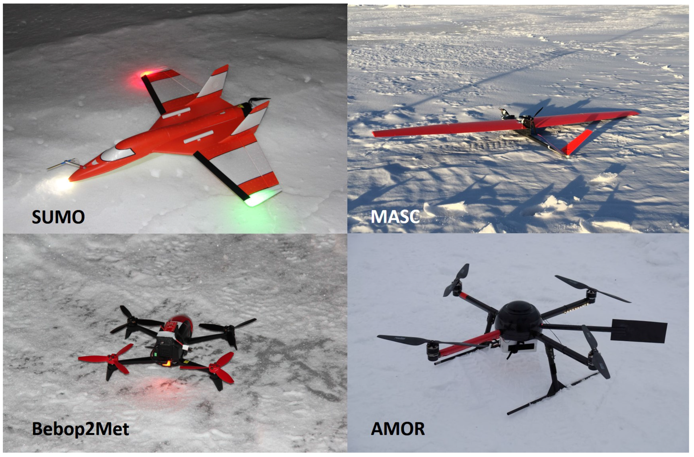
In order to obtain detailed information on the atmospheric state across the entire ABL and parts of the free atmosphere, a number of different UAV (Figure 2), both fixed and rotary-wing systems, were operated in the area around the main field site. A short description of the systems used during the campaign and their capabilities are given below.
The Small Unmanned Meteorological Observer (SUMO) [83,84] is a small fixed-wing UAV, equipped with the Paparazzi autopilot system and a set of basic meteorological sensors. The data acquisition system of the SUMO also records the aircraft’s position and attitude, provided by an on-board Global Navigation Satellite System (GNSS) and an Inertial Measurement Unit (IMU). The SUMO is designed to take atmospheric profiles up to 5000 m and can be operated in wind speeds of more than 15 m   s −1. Under cold environmental conditions, the flight time is typically 45 min . The most important sensor specifications are summarized in Table 3. The meteorological sensors for T and R H are placed a fair distance from the battery and motor on top of the wings to assure good ventilation during flight. In addition to the directly-measured meteorological parameters, like temperature, relative humidity, and pressure, the horizontal wind speed and direction can be estimated by applying the “no-flow-sensor” wind estimation algorithm described in reference [68].
The Multi-purpose Airborne Sensor Carrier (MASC-2) is an electrically-powered, single engine, pusher aircraft of 3.5 m wing span and a total weight of 6 kg , including a scientific payload of 1.0 kg [85]. This UAV is equipped with the ROCS (Research Onboard Computer System) autopilot system developed at the University of Stuttgart. Its endurance under polar conditions is up to 90 min at a cruise speed of 22 m   s −1. For the measurement of turbulence along horizontal straight flight legs and other atmospheric parameters, MASC-2 carries a scientific payload, as summarized in Table 4 and described in detail in [86,87,88]. The sensors are placed in a special sensor holding unit which is attached to the aircraft directly above the nose to face air that is as undisturbed as possible. The 3D-wind vector and the temperature measurements are capable of resolving turbulence up to frequencies of approximately 30 Hz , allowing turbulent fluctuations to be resolved in the sub-meter range. The data from these sensors is oversampled with an acquisition frequency of 100 Hz . Each component of the measurement system aboard MASC-2 was tested in the lab and during flight. The sensors were calibrated and airborne gathered data were validated by comparison to both other measurement systems and theoretical expectations [85,86,87].
A new UAV based on the the miniTalon produced by X-UAV with an EPP airframe of 120 c m wingspan and 83 c m length that was designed to carry a higher payload (up to 1000 g ) was tested during the campaign. The system is a further development of the SUMO by Lindenberg und Müller GmbH & Co. KG and GFI, with increased dimensions. It allows for the integration of an additional turbulence sensor package (Aerosonde five-hole probe), significantly higher air speeds (up to 25 m   s −1), and longer endurance (ca. 90 min ). The turbulence sensors are placed in the nose facing forward, whereas the temperature and humidity sensors are mounted on top of the fuselage, well separated from the battery and motor. Aside from these differences, the miniTalon is equipped with the same Paparazzi autopilot system and the same basic sensor package as described above (Table 3).
The Bebop2Met is based on Bebop2 by Parrot, a small, commercially-available multicopter with a weight of about 500 g and a diameter of roughly 50 c m . The system was modified for our purposes by adding meteorological sensors (Table 3) integrated into a 3D-printed frame attached on top of the battery, as well as by running the Paparazzi autopilot software on the original processor. The sensors for T and R H are placed a few centimeters above one of the propellers on a thin side arm. Tests have shown that the sensors are well ventilated and that the flow at this location is fairly horizontal. The flight time under cold environmental conditions is typically in the range of 20 min , and it can only be operated safely in weak and moderate wind conditions below 10 m   s −1. Typical flight operations include maneuvers such as hovering at a fixed position and altitude and vertical profiles at a fixed location with a constant vertical speed.
The Advanced Mission and Operation Research (AMOR) multicopter UAV was designed to fly in environmental monitoring missions [89], including meteorological campaigns in polar regions. The central airframe, the side arms, the landing gear, and the 15 inch propellers are made of carbon-reinforced plastic. The empty weight of the UAV is 1.5 kg , and the maximum takeoff weight is 4.9 kg . Depending on the environmental conditions, the battery, and the payload, the maximum flight time is approximately 60 min , and the UAV can be operated in winds of up to 15 m   s −1. Due to the cold conditions and the relatively short profiling missions during Hailuoto-I, AMOR flights took typically about 5 min . The Advanced Meteorological Onboard Computer (AMOC) receives the sensor data, fuses the data sets with the IMU and GNSS data sets, and stores them on a µSD card. A fast temperature sensor based on a 25 μ m thermocouple wire, a factory calibrated HYT 271 RH sensor, and a Digi Pico P14 Rapid RH sensor provide the meteorological standard data sets. A pressure sensor provides the altitude above ground level, and a Melexis thermopile sensor provides the surface temperature data, as shown in Table 5. The sensors are mounted on a horizontal tube well outside the downwash of the propellers.

2.1.3. Remote-Sensing

For observations of the 3D-wind field over our study area, we deployed a scanning wind LIDAR (Leosphere Windcube 100s) on the shoreline (Figure 1). The Windcube 100s is a pulsed wind LIDAR system operating at a wavelength of 1.54 μ m and a pulse energy of about 10 μ J . It has a maximum range for wind measurements of 3.5 k m at a range gate resolution of 50 m . The LIDAR was operated in PPI (plan position indicator) mode, i.e., performing azimuth scans over 360 alternating between two elevation angles of 1° and 75 . Further details on the chosen settings are summarized in Table 6.
A vertically-pointing, single-antenna version of the LATAN-3M SODAR system [90] was installed on the sea ice at a distance of about 50 m from the coastline (Figure 1) on 8 February. The SODAR has a frequency-coded sounding signal which allows several measurements per range gate, thus providing higher data availability and quality compared to single-frequency signals. The frequency-coded signal includes eight consecutive 50 m s pulses with frequencies of 3.32, 3.46, 3.58, 3.66, 3.76, 3.9, 4.02 and 4.13 kHz . The vertical measurement range is from 10 m to 340 m , even though the lowest and highest levels typically suffer from poor data availability. At the lowest 3 to 4 levels, the data availability is reduced, since measurements are only based on the first few frequencies as the sampling starts immediately after the transmission of the last frequency. On the other hand, the data availability from the upper levels is often limited by atmospheric conditions because of the lack of thermal turbulence from which the acoustic echoes originate. The measured parameters are the intensity within the main spectral peak of the return signal and the adjacent band and the Doppler shift of the peak, expressed in terms of radial velocity. The parameters are estimated for each range gate with 3 s -resolution ( 0.33 Hz). From the data, it is possible to derive, for example, profiles of mean vertical velocity and its variance. Previously, this SODAR has been used to detect wind shear driven turbulence, convective turbulence, strong katabatic flows, and moist air advection with wave structures in the stably stratified ABL [91].

2.2. UAV Operations

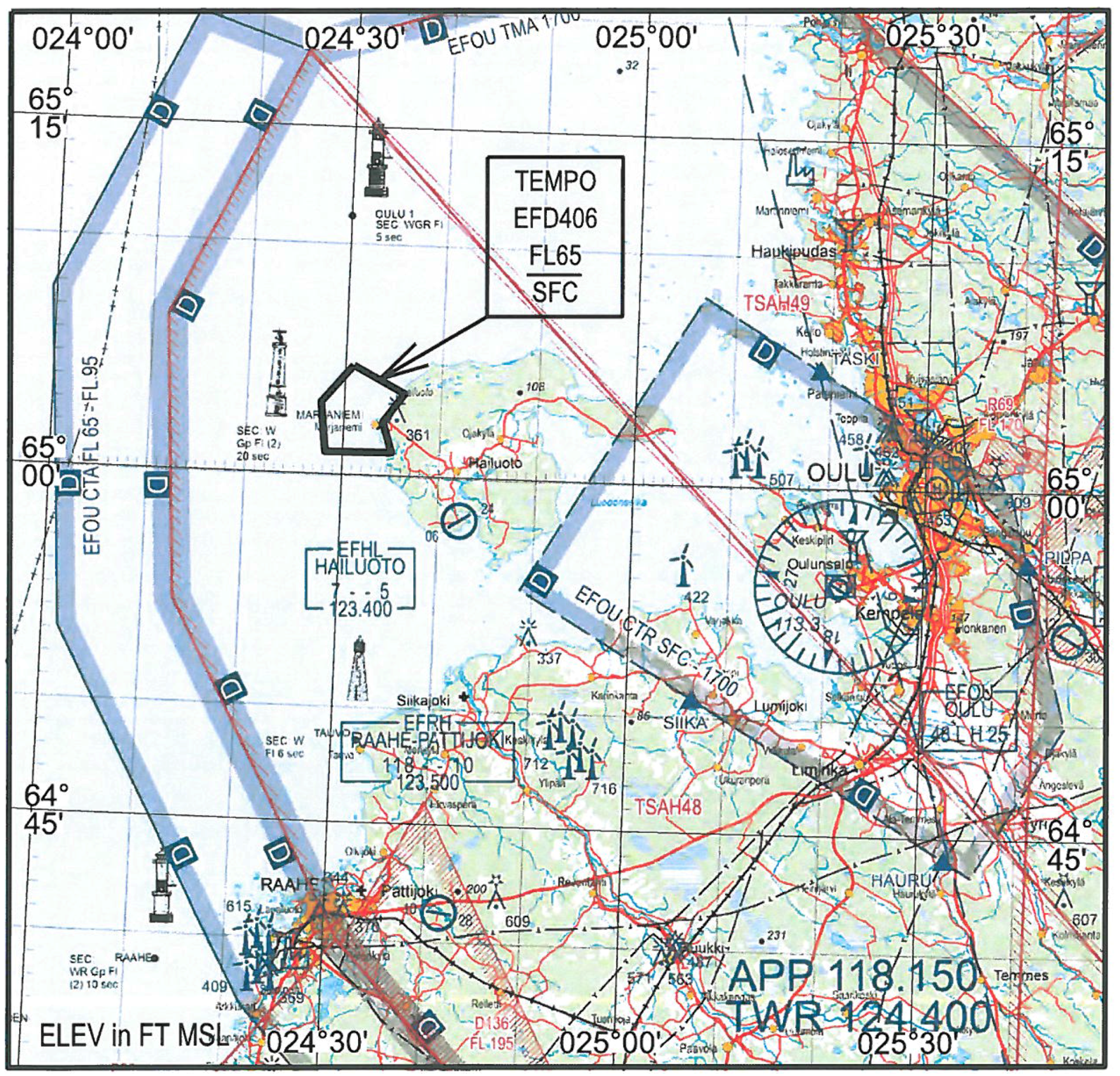
Flights taking place at altitudes of less than 150 m agl and with visual contact to the aircraft can be carried out without any restrictions. Since parts of our operations exceeded these limitations, specifically, the maximum allowed altitude, an application was made for the establishment of a temporary danger area (D-Area), which was granted by the Finnish Aviation Agency for the core period of our campaign. The D-Area (Figure 3) extended from our field site 3 k m to 4 k m along the coast in Southern and Northeastern directions and about 5 k m off-coast to the west and northwest. The vertical extent was from the surface up to flight level 65 ( 6500 ft or 1981.2 m ), but we limited our operations to a maximum target altitude of 1800 m to ensure a good safety margin. The D-Area had to be reserved on a daily basis on the last working day preceding the activities by sending a corresponding request to the airspace management and control (AMC) unit. Before the actual start of UAV operations, we had to contact the responsible AMC unit at Oulu airport to activate the D-Area. If aircraft were passing through or other operations compromised flight safety, the AMC unit could contact us and all operations had to be cancelled immediately. The end of the UAV activities was again reported from our side to AMC to deactivate the D-Area.
The different aircraft types were used for specific missions in the vicinity of our ground-based measurement systems. The typical locations of these flight missions are indicated in Figure 1. All UAVs applied could be operated with a few minutes delay between landing and the next launch, since this usually only requires the installation of new batteries and the start of a new flight mission in the GCS. Apart from MASC-2, which was started with the help of a bungee, all other UAVs could be launched without any technical support, i.e., from ground or hand launch for the multicopters and fixed-wing aircraft, respectively. However, only the multicopter systems, which were mainly used for ABL profiles, were operated at high repetition frequencies during intense observation periods.
The SUMO system can climb very efficiently and was mainly used to obtain vertical profiles up to an altitude of roughly 1800 m . These profiles were achieved by a helical flight pattern with a radius of 120 m and an ascent and descent rate of roughly 2 m s −1. The main purpose of these missions was to obtain several atmospheric profiles per day, covering the ABL and the lower part of the free atmosphere, reflecting larger scale variations in the atmospheric background state. In total, SUMO performed 39 scientific flights during the campaign.
The flight patterns of the MASC-2 and the miniTalon, which were both designed for airborne turbulence measurements, consisted of horizontal race tracks at different altitudes between 20 m agl to 400 m agl. The race tracks, two parallel straight legs of about 600 m to 1500 m length connected by half circles for turning the aircraft, were typically aligned in the main wind direction. The data observed with the high-resolution wind and temperature sensors on these legs were used to provide turbulent parameters at higher levels. MASC-2 flights were typically carried out several times per day and partially repeated after 2 h . During the campaign, the miniTalon was only used for one day (three measurement flights) for testing and validation against the MASC-2 system, which was operated simultaneously. The data from these three miniTalon flights are not the subject of this article, since sophisticated data processing algorithms must be developed for the further analysis. The analysis of the 14 scientific MASC-2 flights is also beyond the scope of this article.
Two multicopter systems were utilized to obtain profiles at a very high vertical resolution within the ABL. In order to gain detailed information on the evolution of the ABL, these profiles were repeated almost continuously during intensive operation periods. Due to the more sophisticated sensor package with partially very short response times, the AMOR system is capable of probing the ABL with higher accuracy, whereas the Bebop2Met profiles are comparably smooth. However, this was partially compensated by operating the Bebop2Met at a slower ascent rate. Due to technical problems, the AMOR system could only be operated during the very end of our campaign.
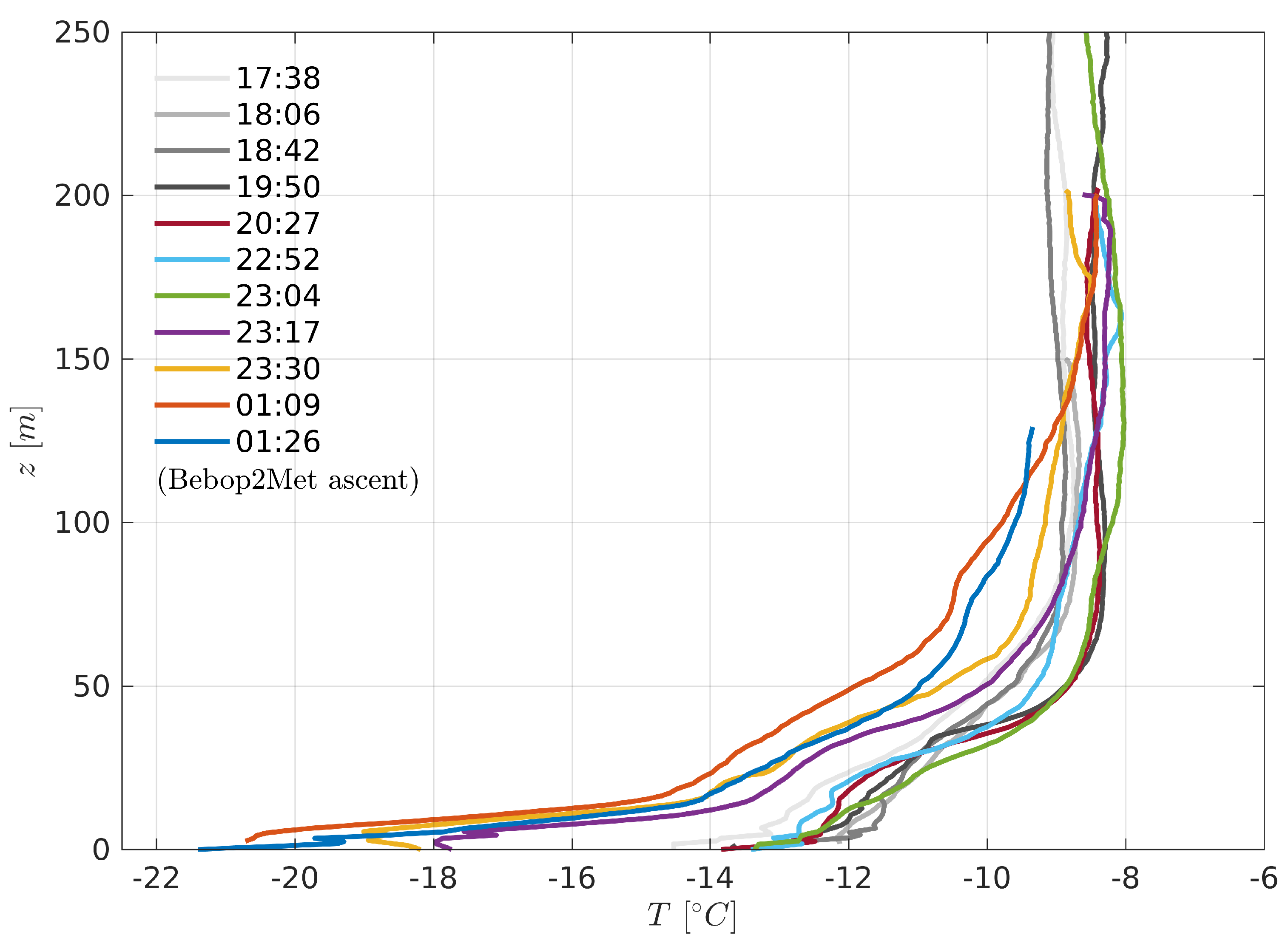
The Bebop2Met UAV was operated on vertical profiles, ranging from 0 m agl and typically 200 m agl or even higher ( 400 m agl) when the atmospheric conditions allowed for it. The atmospheric profiles were performed at a fixed location at a distance of about 10 m to 20 m from the meteorological mast. In order to optimize the vertical resolution of these surface and boundary layer profiles, the vertical climb rate was set to 0.5 m   s −1 below 10 m agl and 1 m   s −1 above. The flights took typically 15 min to 20 min and could be repeated after a ground time of approximately 5 min . For comparison to the mast observations and the calibration of the (experimental) wind estimation algorithm, the Bebop2Met was held at a fixed altitude of 2 m agl to 4 m agl for 1 min to 2 min .
The maximum height of the AMOR multicopter profiles was typically 200 m agl. In order to operate the AMOR UAV safely in the vicinity of the other UAV and the meteorological mast on the sea ice, the start and landing site was chosen to be closer to the shore side. After the takeoff to 5 m agl, the flight was continued at the final location of the profile, approximately 20 m further towards the seaside. The lowest part of the ABL was sampled with a vertical climb speed of 1 m   s −1, resulting in a very high temperature resolution of approximately 0.1 m .

3. Data and Methods

3.1. Data Processing

The data from the land-based AWS-FMI is routinely checked and processed by the Finnish Meteorological Institute and can thus be used as is. All other data were visually inspected for obvious errors. Furthermore, system specific data processing procedures were applied.
The slow-response AWS-ice data were checked for their physical range, and obviously erroneous data were removed. The directional offsets of the wind vanes were corrected to face true north, and all three wind vanes were aligned to result in the same wind direction under conditions with neutral stratification. Due to the distance and large difference in measurement height, no such correction was applied in order to align our wind direction observations with the ones taken over land at AWS-FMI. The short-wave radiation (I) showed small negative values during the night, which were used to apply an offset correction to the entire data set by forcing the minimum value to equal zero.
The EC data was processed using the TK3.11 EC software package [92] producing 30-min, 10-min, and 1-min averaged turbulence quantities, like variance, turbulent fluxes of sensible and latent heat, and momentum. The following settings and corrections were applied: de-spiking by applying a 7-SD threshold; 10% maximum allowed number of missing/bad values; double rotation; Moore, Schotanus, and WPL density corrections; cross-correlation to maximize covariance; stationarity tests; and integral tests on developed turbulence. The resulting data was quality flagged using a three-level flagging system, ranging from 0 to 2. In accordance with the Spoleto agreement, a flag of 0 indicated data of high quality, 1 indicated intermediate quality and 2 indicated poor quality [92]. For the following analyses, we included all EC data with a flag of 0 or 1.
In addition to the directly measured parameters, like T, R H , and p, obtained by the SUMO, the horizontal wind speed (U) and direction ( D i r ) were estimated by applying the “no-flow-sensor” wind estimation algorithm described by [68]. All SUMO data were interpolated to a common frequency of 4 Hz in order to provide a consistent data set.
The Bebop2Met also provides direct profile measurements of T, R H and p, of which only data during ascent was used due to possible downwash contamination during decent. The pressure data at the time of takeoff and landing were used to remove linear trends in the surface pressure which have commonly been observed to cause altitude errors of a few meters towards the end of a flight. Getting reliable altitude information is crucial, especially for observations of the lowermost layers if, e.g., surface-based inversions are to be resolved correctly. Like for the SUMO system, all data were interpolated to a common frequency of 4 Hz . In addition, attempts were made to retrieve wind speed and direction estimates from the aircraft pitch and roll information, following the method of [93]. Due to the design of the Bebop2 with a long but slim body, this method can only be applied reliably if the cross-wind component affecting the aircraft is much smaller than the front-wind component. Since an autopilot algorithm for turning the aircraft into the wind was not implemented during the campaign, the wind speed and direction data from the Bebop2Met have to be considered experimental with corresponding larger uncertainties.
The AMOR pressure data, used to compute the height above ground level of the UAV, was smoothed by applying a moving average. The data of the humidity sensors were recomputed, taking into account the response time and thereby, mapping the correct values to the corresponding heights.
All SODAR data with a signal-to-noise ratio (SNR) below 2 dB were removed from the further analyses. From the filtered SODAR data, we computed 10-min averaged profiles of the vertical velocity and its variance. The attenuated backscatter signal, measured directly by the SODAR, was used to estimate the ABL height. When the top of a thermally-stratified ABL fell within the sounding range, the pattern of echo-signal was used to determine the ABL height. The latter was determined by visual inspection of echograms and return-signal profiles, as the height where the echo intensity of a pronounced echoing layer sharply decreases. This method was chosen as the echo-intensity is a reliable indicator for mixing, in contrast to the standard deviation of the vertical velocity, σ w , that is often wave-dominated in the SBL and therefore, is not a proper indicator for turbulence.
The LIDAR data obtained from the Windcube 100s were already filtered for acceptable carrier-to-noise, ratio, i.e., C N R > 23 dB. An additional check was made for the low elevation data, since this also contains clutter from hard targets such as buildings, the shore, etc. A clutter map was used to remove hard targets, which have a very high SNR and a radial velocity of zero. Furthermore, all points with an instrumental wind speed error greater than 0.5 m   s −1 and unphysical wind speed values exceeding 30 m   s −1 were removed. The radial wind speed measurements were used to compute time series of horizontal wind profiles from both PPI scanning patterns, applying the velocity-azimuth-display (VAD) technique [94]. The VAD technique assumes horizontal homogeneity, and the applied method checks this assumption by testing the collinearity. Profile time series of w 2 ¯ from the SODAR and U ¯ from the LIDAR are available as Supplementary Materials (Section 6). Furthermore, deviations from the mean state over one entire scan were used to compute turbulent statistics of the flow.

3.2. Data Availability

The data availability for the different measurement systems is shown in Figure 4. The FMI permanent weather station close to the lighthouse is part of the official Finnish weather observation network and is operational year-round. Data from this station was therefore available without major quality issues for the entire observation period. The automatic weather station, installed on the sea ice, was operated between 11 and 27 February. Due to a damaged backup battery, which was causing a drop in voltage, some data was lost. In particular, the slow-response data seemed to be affected by this issue. The EC system, running on the same data logger, stopped recording on 13 February due to a broken data cable from the sonic anemometer, which was replaced on 15 February. Furthermore, some of the EC data was of poor (flag 2, see Section 3) or intermediate quality (flag 1). Good and intermediate quality data are marked in green and orange in Figure 4 and were both used for further analysis, whereas poor quality data were removed. The optical lens of the LIDAR was subject to significant icing from the inside, especially at the beginning of the campaign. After defrosting the lens several times, this was not an issue any longer, but probably, due to very low aerosol concentration, the carrier-to-noise ratio (CNR) was rather poor for most observed levels for almost the entire campaign. The SODAR system was subject to flooding due to snow melt and water pushing up through the ice, causing some loss of data in the middle of our campaign. Green and orange colors in Figure 4 refer to the availability of instantaneous observations used to compute a 10-min average. For the good quality data, the lower threshold was 66.7% and for limited quality data, it was 33.3%.
The operation of the different UAVs requires significant manpower, typically involving one safety pilot and one ground control station operator. These systems were therefore mainly operated during intensive observational periods, when the atmospheric conditions were most interesting, i.e., strong static stability and weak winds in the SL. Smaller technical problems and human endurance during rough environmental conditions prevented higher numbers of flights. A fair amount of flights were also carried out during conditions when the stability was relatively weak. In total, 139 scientific flight missions were carried out during the campaign and were distributed as follows: 53 Bebop2Met; 39 SUMO; 30 AMOR; 14 MASC-2; and 3 miniTalon flights. Around one third of the flights (39%) were carried out during conditions with strong atmospheric stability ( R i B > 0.2 ). For 12% of the cases, the 2-m wind speed was, in addition, below 0.5 m   s −1. The irregular flight times, with a focus on stable conditions and rather moderate and low wind speeds, as well as the maximum flight altitudes of the different UAV systems, may have caused a significant sampling bias. It is therefore not recommended for general conclusions to be drawn based on the UAV data alone. These data should primarily be used for the analysis of case studies.

4. Synoptic Situation and Sea Ice Conditions

The analysis of the synoptic situation, including the passages of fronts and sea ice conditions was based on the daily FMI operational weather analysis and ice charts. Until recently, the Bothnian Bay has been entirely frozen every winter. However, the ice thickness, the maximum annual ice extent, and the length of the ice season have shown decreasing trends in recent decades [95]. Winters 2014/2015 (Uotila2015) and 2015/2016 were the first for which we can be certain that parts of the Bothnian Bay remained ice-free. The maximum ice extent is typically reached in March. In the shallow waters close to the coast, land-fast ice prevails and can grow up to a thickness of 0.8 m . Even in mild winters, the level ice thickness reaches 0.3 m to 0.5 m . The land-fast ice is typically free of leads, and the compact sea ice field with snow pack on top effectively insulates the atmosphere from the relatively warm sea.
The sea ice season 2016/2017 was mild in the Baltic Sea. Its length in the Bothnian Bay was, however, close to the average of 1965–1986 (reference period used in FMI ice service). The ice growth started during the first half of November 2016 and was fast during a cold period in early January, leading to an overall ice extent of 44,000 km 2 in Bothnian Bay. Shortly thereafter, temperatures increased and for the rest of the month, mild southwesterlies prevailed, preventing new ice formation and packing the ice densely towards the coast within Bothnian Bay. By the end of January, the Baltic Sea ice extent had reduced to only 28,000 km 2 .
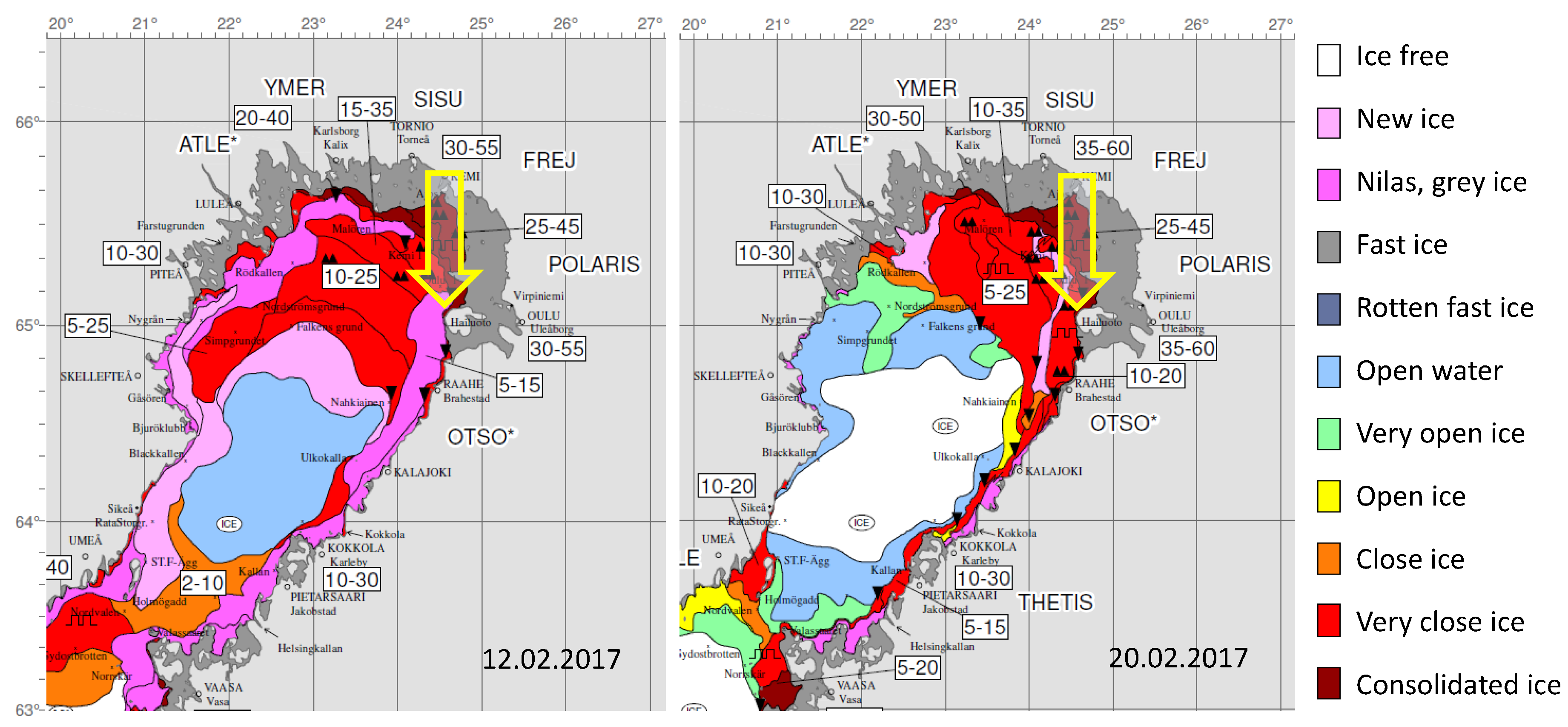
In the beginning of February, a large high pressure system strengthened over Finland, causing fair weather and occasional extremely cold temperatures. Especially from 6 to 9 February, there were very cold temperatures in most of the country. The ice extent increased then rapidly, and a maximum ice extent in the Baltic Sea of 88,000 km 2 was observed on 12 February. At this time, Bothnian Bay was almost completely ice-covered by 10 c m to 25 c m thick drift ice, and the thickness of the land-fast ice was between 5 c m to 55 c m , as shown in Figure 5 (left panel). In the middle of February, a westerly to northwesterly flow pattern strengthened over the region, causing dry and warm Föhn wind from the Scandinavian Mountains. Over Bothnian Bay, the ice field was packed against the Northeastern coast, and a large ice-free area in the center of the Bay formed (Figure 5, right panel). Almost all ships to Oulu, Kemi, and Tornio had to be assisted by ice breakers. In the end of February, ice extent of the Baltic Sea was 77,000 km 2 .
On Hailuoto, the 2-m air temperature was 2 C higher and the 10-m wind speed was 0.5 m   s −1 lower than the climatological mean values for February during 1981–2010. In the first week of the ISOBAR campaign Hailuoto-I, from 11 to 18 February, the synoptic-scale conditions were characterized by a high-pressure center, first located over Southern Scandinavia and then moving over Central and Eastern Europe. Low pressure systems were passing over the North Atlantic, Norwegian Sea, and Barents Sea from southwest to northeast, resulting in variable winds, occasionally approaching 20 m   s −1 in Hailuoto (Figure 6). Depending on the air-mass origin, wind speed, and cloud cover, the 2-m air temperature in Hailuoto varied between −17 C to 4 C (Figure 6). By 19 February, the high pressure center had moved north of the Azores, and a small low pressure system passed over Europe during 19 to 24 February. A passage of a warm front resulted in snow fall ( 8 m m water equivalent) on 23 February. From 24 to 27 February, the synoptic situation was dominated by two large low pressure systems, one first centered over Southern Finland, moving towards the northeast, and another one moving from the Denmark Strait to the Faroe Islands. In the saddle region between the lows, clear skies and weak winds allowed the 2-m air temperature, observed at the official weather station, to drop down to 19.1 C during the night of 27 February.

5. Potential of the Data and First Results

The deeper analysis of the comprehensive data set collected during the Hailuoto-I campaign is far beyond the scope of this overview article. Here, we aim to give a general overview of the campaign conditions, mainly based on the SL observations with the eddy covariance technique (Section 5.1). We shortly present the potential to combine the different ground-based in-situ and remote-sensing observations for a detailed characterization of the ABL structure (Section 5.2), and finally, present the results of a case study in a situation where the temperature suddenly decreased by 6 C close to the ground (Section 5.3).

5.1. Surface Layer Observations

The conditions in the SL, observed over the sea ice, are presented in Figure 7, from top to bottom as follows: (a) the turbulent friction velocity, u * = ( u w ¯ 2 + v w ¯ 2 ) 1 / 4 ; (b) the turbulent kinetic energy per unit mass, T K E = 1 / 2 · ( u 2 ¯ + v 2 ¯ + w 2 ¯ ) ; (c) the turbulent sensible heat flux, H S = c p · ρ · w T ¯ ; and (d) the turbulent latent heat flux, L E = λ · w a ¯ . u * and T K E were both highly correlated with the horizontal wind speed, ranging from values close to zero up to roughly 0.75 m   s −1 and 3 m 2 s −2, respectively. Both parameters did not show any obvious dependency on the wind direction (see Figure 6). However, when directional aspects were considered, it has to be taken into account that the sonic anemometer was facing off-shore and that a fair amount of data with flow over the island was flagged by the post-processing software due to potential flow distortion errors from the mast [92]. H S was mostly negative, ranging from −73.6 W   m −2 to 27.5 W   m −2. The strongest negative values of H S , associated with rapid cooling of the ABL, were reached under conditions with strong negative radiation balance (dominated by the outgoing long-wave radiation, I, see also Figure 6d), resulting in moderate values of u * or T K E . Such situations are typically associated with large positive temperature gradients (not shown in detail here). However, the turbulent flux of the latent heat, L E , showed very different values, ranging from −16.3 W   m −2 to 37.0 W   m −2. More than half of the observed values of L E were positive. This is not surprising, as sea ice and snow are saturated surfaces. Hence, if the air relative humidity is below saturation, an upward latent heat flux may occur simultaneously with a downward sensible heat flux. Over Polar oceans, the air relative humidity is at, or very close to, saturation [43], and dry air masses are often advected over the sea ice, allowing sublimation (upward latent heat flux) even if the sensible heat flux is directed downwards. For example, during a Foehn event over the Bothnian Bay in March 2004, [96] observed a relative humidity of 40% with an upward latent heat flux simultaneous to a downward sensible heat flux. In our case, the largest upward latent heat flux was observed on 17 to 18 February 2017 (Figure 7), when the relative humidity was 70% to 80% and wind was coming from the west (Figure 6). Calculation of a three-day backward trajectory applying the Meteorological Data Explorer [97] indeed suggested a Foehn event with adiabatic subsidence heating when the air mass descended down the mountain slopes in Northern Sweden.
Figure 8 shows the time series of the stability parameters: (a) Monin–Obukhov (MO) stability parameter, ζ = z / L with z being the measurement height and L the Obukhov length, defined as L = ( θ v · u * 3 ) / ( κ · g · w θ v ¯ ) ; (b) the flux Richardson Number, R f = ( g · w θ v ¯ ) / ( θ v · u w ¯ · U ¯ / z ) ; (c) the bulk Richardson Number, R i B = ( g · Δ θ v · Δ z ) / ( θ v ¯ · ( Δ U ) 2 ) ; (d) the difference in potential temperature, Δ θ , between the 4 m and 1 m levels, as observed over the sea ice; and (e) the atmospheric boundary layer (ABL) height ( h A B L ), estimated from the SODAR observations. The gray vertical lines indicate events with U < 0.5   m   s −1, the threshold for the near-calm stable boundary layer (SBL), when, according to [98], the relationship between the fluxes and the weak mean flow breaks down and the use of the traditional stability parameters, e.g., ζ , R i B , R f , becomes difficult. The dynamic stability, ζ , covers a wide range of different stabilities from weakly unstable (4%), ζ < 0.1 , to stable or very stable (29%), ζ 0.05 , with most observations in the near-neutral range (66%), 0.1 ζ < 0.05 .
However, a fair number of cases (27%) with very stable stratification ( R i B > R i c r = 0.2 ) were found. All such cases were related to weak wind conditions, when u * or u w ¯ approach zero, resulting in high stability values. During the observation period, 34 cases (30-min averages) of a near-calm SBL were observed, which frequently resulted in very sharp surface inversions with potential temperature differences between the 4 m and 1 m levels reaching up to 6 C and greater. h A B L was typically below 100 m during these cases and reached values as low as 20 m . It has to be noted that no absolutely reliable algorithm for determining h A B L from SODAR observations exists and that our estimates are partially based on human judgment and therefore, are somewhat subjective. Furthermore, no reliable estimates could be provided when the data quality of the SODAR observations was too poor or when h A B L exceeded the vertical range of the instrument, i.e., h A B L > 340   m .

5.2. Profiles

5.2.1. Composite Profiles from Multiple Systems

Figure 9 shows an example of atmospheric profile measurements for temperature, T, and wind speed, U, from different systems, i.e., AWS-ice at 1magl, 2magl and 4 m agl; AWS-FMI (only U) at 29 m asl; Bebop2Met (only T) from 0 m agl to 350 m agl; SUMO from 40 m agl to 1800 m agl; and LIDAR from roughly 200 m agl to 450 m agl. The displayed AWS and LIDAR data represent time-averaged data for the time period indicated in the legend, whereas the UAV data correspond to one single ascent. The Bebop2Met T data is bin-averaged with 10 m increments, while for the SUMO data, the bins are 25 m , and the LIDAR data points are separated by roughly 24 m . It also has to be noted that we used three different scales for the y-axis to increase the level of detail in the SL towards the surface.
During the morning of 26 February, the ABL was stably stratified with a surface-based inversion reaching up to about 300 m , as well as several smaller, but also sharp inversions further above. All three systems matched very well with temperature differences in the range of 0.5 C , which could have been caused by differences in the sampling times and differences in the time and spatial averaging procedures applied to the data.
The profile of the horizontal wind speed has a gap from 4 m agl to 40 m agl, since no reliable estimates from the Bebop2Met UAV could be computed due to a significant cross-wind component acting on the multicopter and the lack of LIDAR data with sufficient CNR. The SUMO data, however, indicated the existence of an LLJ with a peak velocity of about 7.5 m   s −1, located just below 100 m , which also corresponds well to the notable decrease in the vertical temperature gradient observed at this level. At the levels between the 200 m to 500 m , where LIDAR data was available, and in the vicinity of the 29-m wind measurement at AWS-FMI, the agreement between the observations within 1 m   s −1 was fairly good, given the differences in the observation and data processing principles.

5.2.2. Evolution of Temperature Profile

The evolution of the thermal structure of the ABL during the night from 26 to 27 February is shown in Figure 10. The observations were taken by the small multicopter UAV Bebop2Met in a distance of roughly 20 m from the meteorological mast installed on the sea ice (Figure 1), and cover the time period from 17:38 UTC to 01:26 UTC (mean time of the ascent profiles). All profiles indicated a sharp, surface-based inversion reaching up to about 50 m . Above this level, the vertical temperature gradient decreased and eventually approached an isothermal gradient. The temperature above 150 m remained at roughly −9 C to −8 C for the entire 8 h period, with weak signs of warm air advection between 18:42 UTC and 19:50 UTC. The lowermost 50 m or so were, however, subject to rapid cooling, with temperatures at the surface decreasing from −14 C to −22 C after 23:04 UTC. During this event, the vertical temperature difference in the lowermost 20 m increased from values of around 2 C to 6 C , causing a very strong static stability and inhibiting almost any vertical movement (see Section 5.3). The same behavior was also detected in the time series of profiles from the AMOR system which was operated roughly at the same time period (not shown here).

5.3. Case Study on Very Stable Conditions—26 to 27 February

During the last night of the campaign, 26 to 27 February, we observed a very stable case, which was characterized by strong, rapid temperature changes observed at AWS-ice. Almost the entire night was cloud-free without any indications of fog or other significant weather, according to the official weather observations from AWS-FMI. The radiation balance was strongly negative, especially until 0:00 UTC, and radiative cooling was the dominant term in the surface energy balance (compare Figure 6). Figure 11 shows the corresponding time series of (a) T; (b) U; (c) D i r ; (d) R H ; and (e) w 2 ¯ from the two locations over land (except for w 2 ¯ ) and sea ice for the period between 16:00 and 8:00 UTC. All data are based on a 1-min averaging period, except for the data from the land-based AWS-FMI, which was only available at a resolution of 10 min .
Until around 23:00 UTC, the conditions were relatively stationary, with temperatures between −15 C to −12 C and wind speeds between 1 m   s −1 to 3 m   s −1 close to the ice surface and 5 m   s −1 to 7 m   s −1 at 29 m asl. The vertical gradients and local differences between land and sea ice were generally small. The 29-m wind speed decreased from 6.5 m   s −1 to 1.5 m   s −1, before it started increasing again at about 4:20 UTC.
At about 23:10, a drop in temperature from approximately −13 C to −18 C was observed at the 1 m level over the sea ice (Figure 11a), accompanied by a calming of the near surface winds over the ice (Figure 11b). This initial drop happened within 1 min to 2 min , but the cooling continued and temperatures of 20 C were reached. The same kind of changes, albeit slightly weaker and slower, were observed at the 2 m and 4 m levels, whereas the observations over the slightly elevated land remained fairly constant. The near-surface temperature and wind speed stayed at low values for about 20 min and returned to their previous states at a slower rate within approximately 5 min , starting at the top and penetrating further down. The following warmer phase with a weak flow also lasted for about 20 min . During this first cold episode, the static stability in the SL was much stronger compared to the conditions before and after the episode, with temperature differences of up to 5 C and roughly 0.5 C between the 4 m and 1 m levels, respectively. The vertical gradient of U occasionally became negative during the near-calm events, indicating a decoupling of the near-surface layers. After the first cycle of rapid temperature changes, several similar events followed, which were, however, not as clearly structured as the first one, since the 1 m level and partially, the 2 m level remained at low temperatures with very weak or calm winds. Furthermore, these following events were significantly shorter and occurred with a higher frequency. At about 6:00 UTC—just after sunrise—temperatures at all observation levels started to rise again; the vertical temperature gradient decreased and the oscillations in temperature and wind became much weaker.
During the evening and throughout the night until about 2:00 UTC, the general wind direction at 29 m asl was from north (Figure 11c). During the rest of the night and the morning, the direction shifted to northeast (from about 3:00 to 4:00) and finally, to southwest (from 06:00). Over the sea ice, the wind direction deviated by a few degrees toward the east in the beginning, which might have partially been caused by a small error in the azimuthal sensor alignment. Due to the weak wind speeds below the detection range of our wind vanes, i.e., 0.6 m   s −1, a fair amount of wind direction observations over the sea ice had to be neglected during the calm and cold periods. The available data from these events revealed frequent direction shifts of more than 90 to the east and southeast, with relatively large deviations between the three observation levels. The relative humidity (Figure 11d) and specific humidity (not shown) closely followed the pattern of the temperatures at the corresponding levels, observed at the AWS-ice. The vertical velocity variance, observed with our EC system at 2.7 m asl (lowermost panel in Figure 11), indicated very weak vertical turbulent motion in the order of w 2 ¯ = 0.001 m 2   s −2 during cold episodes. The values were about one order of magnitude higher during the warmer phases. This supports the argument that vertical mixing, or its absence, is causing the observed oscillations. The values of w 2 ¯ were typically up to two orders of magnitude higher before the first event.
The last multicopter profile from this night taken with the AMOR originated from 1:40 to 1:43 UTC during one of the cold and calm events. The corresponding temperature profile is shown in Figure 12a) from ground level to 200 m , together with the AWS-ice data. The AMOR’s downward facing infra-red sensor confirmed the low temperatures of the ice-covered surface ( T I R = 23   C ). The temperature gradient within the lowermost 20 m was extremely strong with a total gradient of Δ T = 10   C . Right above, in the layer from roughly 20 m agl to 60 m agl, there was a remarkably strong variation in temperature, with a superadiabatic lapse rate from about 20 m agl to 40 m agl. The air parcel at about 30 m agl to 40 m agl had the potential to penetrate further down to a level of approximately 5 m agl to 10 m agl, assuming a dry adiabatic descent. This can be interpreted as the signature of a strong, most likely, Kelvin–Helmholtz instability, causing local mixing, which then penetrated further down, causing the SL to switch back from the cold and calm state.
The time series of the attenuated backscatter from the LATAN-3M SODAR (Figure 12b) at the moment of the multicopter profile acquisition was characterized by two echoing layers: one layer within the lowest 20 m and the second one within 60 m to 100 m . The layers nicely correspond to the temperature inversion observed by the multicopter. The evolution of the attenuated backscatter profile clearly shows variability in the vertical structure of the ABL and allows for the estimation of temporal validity frame for multicopter profiles. Furthermore, the elevated inversion layer oscillated with a period of 1 h to 2 h , which could be an indication of gravity-wave activity during this night.

6. Summary and Outlook

The ISOBAR field campaign, Hailuoto-I, in February 2017 resulted in an extensive data set from several different observation systems, including ground-based in-situ and remote-sensing, in addition to airborne observations by various UAVs. The meteorological and sea ice conditions during the campaign did not represent the climatological means in the area with 2 C higher temperatures and significantly less sea ice during most of February, compared to climatological references. Despite the relatively mild conditions, accompanied by a below average sea ice cover and the already significant diurnal cycle with notable short-wave radiation, a valuable data set on the SBL was sampled.
The stability of the SL was mostly near-neutral, but also, a fair amount of very-stable cases ( R i B > R i c r ) occurred during the campaign, typically related to clear sky and weak wind or near-calm conditions. Under very stable conditions, the ABL height, h A B L , estimated from the SODAR data reached values as low as 20 m . In general, wind shear seems to be a very important mechanism for creating turbulence. The long-wave upwelling radiation usually dominated over the other radiation terms and the turbulent fluxes of latent and sensible heat, with the latter also being significant.
A unique approach was made in which data was combined from different profiling systems to create composite profiles, probing the atmospheric column from the surface to an altitude of 1800 m agl with very high resolution in the lowermost layers. The agreement between the different systems was very good, given the systematic differences in the measurement principle, as well as in the vertical and temporal resolutions. Sampling the lowermost 200 m or so repeatedly over several hours gave detailed information on the evolution of the SBL structure, such as a rapid cooling of the lowermost 20 m and other relevant processes like warm air advection. The sampled data also contained at least one longer period of an SBL with very stable stratification and calm winds, which was characterized by a series of turbulent events leading to a rapid warming of the layers close to the ice surface. The UAV and SODAR profiling systems gave additional insight into the nature of these events, suggesting the existence of an elevated source of turbulence which could contribute to the occasional mixing events observed close to the surface.
The experience from this campaign motivated us to conduct a second, even more extensive field experiment. The ISOBAR campaign Hailuoto-II took place at the same site from 1 to 28 February 2018. The collected data from both ISOBAR field campaigns will be the basis for future SBL research studies. A particular focus will be on the combination of the observational data set with modeling approaches on different scales (NWP and LES) and with different levels of complexity (e.g., 3D and single column). The Weather Research and Forecasting (WRF) model [2], run with different surface and boundary layer parameterization schemes, will be evaluated against the observations to better understand the physics and dynamics behind the observed events. For that purpose, we will also perform a series of experiments with the WRF model’s single-column mode, in which the atmospheric column above a single grid point from the 1 k m WRF domain is resolved with very high vertical resolution. This will give a deeper insight into the sensitivity of the SBL to changes in the prescribed surface conditions and model physics.
Accompanying the LES runs will be performed with the Parallelized Large-Eddy Simulation Model (PALM) [99] to reveal SBL structure and dynamics, and virtual UAV measurements will be conducted on-the-fly during the simulation in order evaluate the representativeness of these measurements. The advantage in the LES is that the true state of the ABL is known, and errors induced by the measurement strategy can be directly evaluated. Based on the findings from this investigation, improved UAV flight strategies might be developed. Second, the problem of lacking grid convergence when simulating the SBL with LES will be addressed by applying a modified MOST-based surface boundary condition. Unlike existing boundary conditions, this will not lead to violations of the basic assumptions of MOST and inherent issues in LES modeling as outlined in the introduction. Finally, a series of LES runs shall be employed to evaluate both flux and alternative gradient-based similarity functions [33,34] in the SBL. This work will follow the methodology of the recent work for convective conditions by [100] and will elucidate whether gradient-based similarity functions might be superior to the established flux-based MOST formulation, particularly under very stable conditions.

Supplementary Materials

The following are available online at https://www.mdpi.com/2073-4433/9/7/268/s1: Figure S1: SODAR profile time series of w 2 ¯ , Figure S2: LIDAR profile time series of U ¯ from 1 deg PPI scan, Figure S3: LIDAR profile time series of U ¯ from 75 deg PPI scan.

Author Contributions

Conceptualization, S.T.K., J.R., T.V., B.W., M.O.J., B.M., S.M., A.A.M.H. and J.B.; Data curation, S.T.K., I.S., E.O., R.K., B.W., G.U. and A.S.; Formal analysis, S.T.K., I.S., E.O., R.K., B.W., G.U. and A.S.; Funding acquisition, S.T.K., J.R., T.V., B.W., M.O.J. and S.M.; Investigation, S.T.K., T.V., I.S., E.O., R.K., B.W., A.R., G.U., M.O.J., L.B., M.M., C.L. (Christian Lindenberg), C.L. (Carsten Langohr), H.V., M.H., P.H. and M.S.; Methodology, S.T.K., J.R., M.O.J., B.M., S.M., T.L., A.A.M.H. and G.-J.S.; Project administration, S.T.K., J.R., S.M. and J.B.; Resources, J.R., T.V., R.K., M.M., C.L. and J.B.; Software, S.T.K., I.S., E.O., R.K., B.W., M.O.J., A.S. and M.M.; Supervision, J.R. and T.V.; Validation, S.T.K., J.R., I.S., E.O., R.K., B.W. and G.U.; Visualization, S.T.K., J.R., R.K., B.W., G.U. and A.S.; Writing – original draft, S.T.K., J.R., T.V., I.S., R.K., B.W., A.R., G.U., B.M., S.M., T.L., A.A.M.H. and G.-J.S.; Writing—review & editing, S.T.K., J.R., T.V., I.S., R.K., B.W., A.R., M.O.J., L.B., B.M., S.M., T.L., A.A.M.H., G.-J.S. and A.S.

Funding

This research was funded by Norges Forskningsråd (the Research Council of Norway) grant number [251042/F20] and [277770].

Acknowledgments

The Hailuoto-I campain was integral part of the ISOBAR project funded by the Research Council of Norway (RCN) under the FRINATEK scheme (project number: 251042/F20). The scanning wind LIDAR system (Leosphere WindCube 100S) has been made available via the National Norwegian infrastructure project OBLO (Offshore Boundary Layer Observatory) also funded by RCN (project number: 277770). The authors are grateful to Anak Bhandari for all the help and assistance in the preparation of and clean-up after the campaign and the organization of the transport of all equipment. Special thanks is given to Hannu, Sanna and Pekka from Hailuodon Majakkapiha for the provision of all required logistics, their hospitality, and the fantastic food that was essential to keep the spirit during the campaign up. Finally we would like to dedicate this article to our colleague, Zbig Sorbjan, who passed away on February 19 while the Hailuoto campaign was running. His ideas and enthusiasm were a driving force and steady motivation during the application process for ISOBAR, and, for sure, one important factor for getting the funding finally approved. We will miss his knowledge and expertise for the analysis of the collected data during the next years.

Conflicts of Interest

The authors declare no conflict of interest. The founding sponsors had no role in the design of the study; in the collection, analyses, or interpretation of data; in the writing of the manuscript, and in the decision to publish the results.

References

  1. Mahrt, L. Stably Stratified Atmospheric Boundary Layers. Annu. Rev. Fluid Mech. 2014, 46, 23–45. [Google Scholar] [CrossRef]
  2. Skamarock, W.; Klemp, J.; Dudhia, J.; Gill, D.; Barker, D.; Duda, M.; Huang, X.Y.; Wang, W. A Description of the Advanced Research WRF Version 3; Technical Report NCAR/TN-475+STR; NCAR: Boulder, CO, USA, 2008. [Google Scholar] [CrossRef]
  3. Tjernström, M.; Žagar, M.; Svensson, G.; Cassano, J.J.; Pfeifer, S.; Rinke, A.; Wyser, K.; Dethloff, K.; Jones, C.; Semmler, T.; et al. Modelling the Arctic Boundary Layer: An Evaluation of Six ARCMIP Regional-Scale Models Using Data from the SHEBA Project. Bound.-Layer Meteorol. 2005, 117, 337–381. [Google Scholar] [CrossRef]
  4. Cuxart, J.; Holtslag, A.A.M.; Beare, R.J.; Bazile, E.; Beljaars, A.; Cheng, A.; Conangla, L.; Ek, M.; Freedman, F.; Hamdi, R.; et al. Single-Column Model Intercomparison for a Stably Stratified Atmospheric Boundary Layer. Bound.-Layer Meteorol. 2005, 118, 273–303. [Google Scholar] [CrossRef] [Green Version]
  5. Mauritsen, T.; Svensson, G.; Zilitinkevich, S.S.; Esau, I.; Enger, L.; Grisogono, B. A Total Turbulent Energy Closure Model for Neutrally and Stably Stratified Atmospheric Boundary Layers. J. Atmos. Sci. 2007, 64, 4113–4126. [Google Scholar] [CrossRef]
  6. Holtslag, A.; Svensson, G.; Baas, P.; Basu, S.; Beare, B.; Beljaars, A.; Bosveld, F.; Cuxart, J.; Lindvall, J.; Steeneveld, G.; et al. Stable Atmospheric Boundary Layers and Diurnal Cycles–Challenges for Weather and Climate Models. Bull. Am. Meteorol. Soc. 2013, 94, 1691–1706. [Google Scholar] [CrossRef]
  7. Lüpkes, C.; Vihma, T.; Jakobson, E.; König-Langlo, G.; Tetzlaff, A. Meteorological observations from ship cruises during summer to the central Arctic: A comparison with reanalysis data. Geophys. Res. Lett. 2010, 37. [Google Scholar] [CrossRef] [Green Version]
  8. Atlaskin, E.; Vihma, T. Evaluation of NWP results for wintertime nocturnal boundary-layer temperatures over Europe and Finland. Q. J. R. Meteorol. Soc. 2012, 138, 1440–1451. [Google Scholar] [CrossRef] [Green Version]
  9. McNider, R.T.; Christy, J.R.; Biazar, A. A Stable Boundary Layer Perspective on Global Temperature Trends. In IOP Conference Series: Earth and Environmental Science; IOP Publishing: Bristol, UK, 2010; Volume 13, p. 012003. [Google Scholar] [CrossRef]
  10. Esau, I.; Davy, R.; Outten, S. Complementary Explanation of Temperature Response in the Lower Atmosphere. Environ. Res. Lett. 2012, 7, 044026. [Google Scholar] [CrossRef]
  11. Pithan, F.; Mauritsen, T. Arctic amplification dominated by temperature feedbacks in contemporary climate models. Nat. Geosci. 2014, 7, 181–184. [Google Scholar] [CrossRef]
  12. Boé, J.; Hall, A.; Qu, X. Current GCMs’ Unrealistic Negative Feedback in the Arctic. J. Clim. 2009, 22, 4682–4695. [Google Scholar] [CrossRef]
  13. Esau, I.; Zilitinkevich, S. On the Role of the Planetary Boundary Layer Depth in the Climate System. Adv. Sci. Res. 2010, 4, 63–69. [Google Scholar] [CrossRef]
  14. Vihma, T.; Pirazzini, R.; Fer, I.; Renfrew, I.A.; Sedlar, J.; Tjernström, M.; Lüpkes, C.; Nygård, T.; Notz, D.; Weiss, J.; et al. Advances in understanding and parameterization of small-scale physical processes in the marine Arctic climate system: A review. Atmos. Chem. Phys. 2014, 14, 9403–9450. [Google Scholar] [CrossRef] [Green Version]
  15. Zilitinkevich, S.; Calanca, P. An Extended Similarity Theory for the Stably Stratified Atmospheric Surface Layer. Q. J. R. Meteorol. Soc. 2000, 126, 1913–1923. [Google Scholar] [CrossRef]
  16. Klipp, C.L.; Mahrt, L. Flux-Gradient Relationship, Self-Correlation and Intermittency in the Stable Boundary Layer. Q. J. R. Meteorol. Soc. 2004, 130, 2087–2103. [Google Scholar] [CrossRef]
  17. Sodemann, H.; Foken, T. Empirical Evaluation of an Extended Similarity Theory for the Stably Stratified Atmospheric Surface Layer. Q. J. R. Meteorol. Soc. 2004, 130, 2665–2671. [Google Scholar] [CrossRef]
  18. Baas, P.; Steeneveld, G.J.; van de Wiel, B.J.H.; Holtslag, A.A.M. Exploring Self-Correlation in Flux-Gradient Relationships for Stably Stratified Conditions. J. Atmos. Sci. 2006, 63, 3045–3054. [Google Scholar] [CrossRef]
  19. Foken, T. 50 Years of the Monin-Obukhov Similarity Theory. Bound.-Layer Meteorol. 2006, 119, 431–447. [Google Scholar] [CrossRef]
  20. Sorbjan, Z.; Grachev, A.A. An Evaluation of the Flux-Gradient Relationship in the Stable Boundary Layer. Bound.-Layer Meteorol. 2010, 135, 385–405. [Google Scholar] [CrossRef]
  21. Grachev, A.A.; Andreas, E.L.; Fairall, C.W.; Guest, P.S.; Persson, P.O.G. The Critical Richardson Number and Limits of Applicability of Local Similarity Theory in the Stable Boundary Layer. Bound.-Layer Meteorol. 2013, 147, 51–82. [Google Scholar] [CrossRef] [Green Version]
  22. Mauritsen, T.; Svensson, G. Observations of Stably Stratified Shear-Driven Atmospheric Turbulence at Low and High Richardson Numbers. J. Atmos. Sci. 2007, 64, 645–655. [Google Scholar] [CrossRef]
  23. Grachev, A.A.; Fairall, C.W.; Persson, P.O.G.; Andreas, E.L.; Guest, P.S. Stable Boundary-Layer Scaling Regimes: The SHEBA Data. Bound.-Layer Meteorol. 2005, 116, 201–235. [Google Scholar] [CrossRef]
  24. Zilitinkevich, S.; Baklanov, A.; Rost, J.; Smedman, A.S.; Lykosov, V.; Calanca, P. Diagnostic and Prognostic Equations for the Depth of the Stably Stratified Ekman Boundary Layer. Q. J. R. Meteorol. Soc. 2002, 128, 25–46. [Google Scholar] [CrossRef]
  25. Mahrt, L.; Vickers, D. Contrasting Vertical Structures of Nocturnal Boundary Layers. Bound.-Layer Meteorol. 2002, 105, 351–363. [Google Scholar] [CrossRef]
  26. Sorbjan, Z.; Czerwinska, A. Statistics of Turbulence in the Stable Boundary Layer Affected by Gravity Waves. Bound.-Layer Meteorol. 2013, 148, 73–91. [Google Scholar] [CrossRef] [Green Version]
  27. Zilitinkevich, S.S. Third-Order Transport due to Internal Waves and Non-Local Turbulence in the Stably Stratified Surface Layer. Q. J. R. Meteorol. Soc. 2002, 128, 913–925. [Google Scholar] [CrossRef]
  28. Steeneveld, G.J.; Wokke, M.J.J.; Zwaaftink, C.D.G.; Pijlman, S.; Heusinkveld, B.G.; Jacobs, A.F.G.; Holtslag, A.A.M. Observations of the radiation divergence in the surface layer and its implication for its parameterization in numerical weather prediction models. J. Geophys. Res. 2010, 115. [Google Scholar] [CrossRef] [Green Version]
  29. Sterk, H.A.M.; Steeneveld, G.J.; Holtslag, A.A.M. The role of snow-surface coupling, radiation, and turbulent mixing in modeling a stable boundary layer over Arctic sea ice. J. Geophys. Res. Atmos. 2013, 118, 1199–1217. [Google Scholar] [CrossRef] [Green Version]
  30. Nieuwstadt, F.T.M. The Turbulent Structure of the Stable, Nocturnal Boundary Layer. J. Atmos. Sci. 1984, 41, 2202–2216. [Google Scholar] [CrossRef] [Green Version]
  31. Zilitinkevich, S.S.; Esau, I.N. Similarity Theory and Calculation of Turbulent Fluxes at the Surface for the Stably Stratified Atmospheric Boundary Layer. In Atmospheric Boundary Layers; Baklanov, A., Grisogono, B., Eds.; Springer: New York, NY, USA, 2007; pp. 37–49. [Google Scholar]
  32. Sorbjan, Z. The Height Correction of Similarity Functions in the Stable Boundary Layer. Bound.-Layer Meteorol. 2012, 142, 21–31. [Google Scholar] [CrossRef]
  33. Sorbjan, Z. Gradient-based Scales and Similarity Laws in the Stable Boundary Layer. Q. J. R. Meteorol. Soc. 2010, 136, 1243–1254. [Google Scholar] [CrossRef]
  34. Sorbjan, Z. Gradient-Based Similarity in the Stable Atmospheric Boundary Layer. In Achievements, History and Challenges in Geophysics; Bialik, R., Majdaski, M., Moskalik, M., Eds.; GeoPlanet: Earth and Planetary Sciences; Springer International Publishing: Berlin, Germany, 2014; pp. 351–375. [Google Scholar] [CrossRef]
  35. Beare, R.J.; Macvean, M.K.; Holtslag, A.A.M.; Cuxart, J.; Esau, I.; Golaz, J.C.; Jimenez, M.A.; Khairoutdinov, M.; Kosovic, B.; Lewellen, D.; et al. An intercomparison of large-eddy simulations of the stable boundary layer. Bound.-Layer Meteorol. 2006, 118, 247–272. [Google Scholar] [CrossRef]
  36. Sullivan, P.P.; Weil, J.C.; Patton, E.G.; Jonker, H.J.J.; Mironov, D.V. Turbulent Winds and Temperature Fronts in Large-Eddy Simulations of the Stable Atmospheric Boundary Layer. J. Atmos. Sci. 2016, 73, 1815–1840. [Google Scholar] [CrossRef]
  37. Maronga, B.; Bosveld, F.C. Key parameters for the life cycle of nocturnal radiation fog: A comprehensive large-eddy simulation study. Q. J. R. Meteorol. Soc. 2017, 143, 2463–2480. [Google Scholar] [CrossRef]
  38. Kawai, S.; Larsson, J. Wall-modeling in large eddy simulation: Length scales, grid resolution, and accuracy. Phys. Fluids 2012, 24, 015105. [Google Scholar] [CrossRef]
  39. Andreas, E.L.; Claffey, K.J. Air-ice drag coefficients in the western Weddell Sea: 1. Values deduced from profile measurements. J. Geophys. Res. 1995, 100, 4821–4831. [Google Scholar] [CrossRef]
  40. Andreas, E.L.; Claffy, K.J.; Makshtas, A.P. Low-Level Atmospheric Jets and Inversions over the Western Weddell Sea. Bound.-Layer Meteorol. 2000, 97, 459–486. [Google Scholar] [CrossRef]
  41. Andreas, E.L.; Jordan, R.E.; Makshtas, A.P. Simulations of Snow, Ice, and Near-Surface Atmospheric Processes on Ice Station Weddell. J. Hydrometeorol. 2004, 5, 611–624. [Google Scholar] [CrossRef]
  42. Andreas, E.L.; Jordan, R.E.; Makshtas, A.P. Parameterizing turbulent exchange over sea ice: The Ice Station Weddell results. Bound.-Layer Meteorol. 2005, 114, 439–460. [Google Scholar] [CrossRef]
  43. Andreas, E.L. Near-surface water vapor over polar sea ice is always near ice saturation. J. Geophys. Res. 2002, 107. [Google Scholar] [CrossRef] [Green Version]
  44. Persson, P.O.G. Measurements near the Atmospheric Surface Flux Group tower at SHEBA: Near-surface conditions and surface energy budget. J. Geophys. Res. 2002, 107. [Google Scholar] [CrossRef] [Green Version]
  45. Vihma, T.; Jaagus, J.; Jakobson, E.; Palo, T. Meteorological conditions in the Arctic Ocean in spring and summer 2007 as recorded on the drifting ice station Tara. Geophys. Res. Lett. 2008, 35. [Google Scholar] [CrossRef] [Green Version]
  46. Jakobson, L.; Vihma, T.; Jakobson, E.; Palo, T.; Männik, A.; Jaagus, J. Low-level jet characteristics over the Arctic Ocean in spring and summer. Atmos. Chem. Phys. 2013, 13, 11089–11099. [Google Scholar] [CrossRef] [Green Version]
  47. Palo, T.; Vihma, T.; Jaagus, J.; Jakobson, E. Observations of temperature inversions over central Arctic sea ice in summer. Q. J. R. Meteorol. Soc. 2017, 143, 2741–2754. [Google Scholar] [CrossRef]
  48. Cohen, L.; Hudson, S.R.; Walden, V.P.; Graham, R.M.; Granskog, M.A. Meteorological conditions in a thinner Arctic sea ice regime from winter through summer during the Norwegian Young Sea Ice expedition (N-ICE2015). J. Geophys. Res. Atmos. 2017, 122, 7235–7259. [Google Scholar] [CrossRef]
  49. Argentini, S.; Viola, A.P.; Mastrantonio, G.; Maurizi, A.; Georgiadis, T.; Nardino, M. Characteristics of the boundary layer at Ny-Alesund in the Arctic during the ARTIST field experiment. Ann. Geophys. 2003, 46, 185–196. [Google Scholar]
  50. Balsley, B.B.; Frehlich, R.G.; Jensen, M.L.; Meillier, Y.; Muschinski, A. Extreme Gradients in the Nocturnal Boundary Layer: Structure, Evolution, and Potential Causes. J. Atmos. Sci. 2003, 60, 2496–2508. [Google Scholar] [CrossRef]
  51. Bosveld, F.C.; Baas, P.; van Meijgaard, E.; de Bruijn, E.I.F.; Steeneveld, G.J.; Holtslag, A.A.M. The Third GABLS Intercomparison Case for Evaluation Studies of Boundary-Layer Models. Part A: Case Selection and Set-Up. Bound.-Layer Meteorol. 2014, 152, 133–156. [Google Scholar] [CrossRef]
  52. Kleczek, M.A.; Steeneveld, G.J.; Holtslag, A.A. Evaluation of the Weather Research and Forecasting Mesoscale Model for GABLS3: Impact of Boundary-Layer Schemes, Boundary Conditions and Spin-Up. Bound.-Layer Meteorol. 2014, 152, 213–243. [Google Scholar] [CrossRef]
  53. Mahrt, L. Bulk formulation of surface fluxes extended to weak-wind stable conditions. Q. J. R. Meteorol. Soc. 2008, 134, 1–10. [Google Scholar] [CrossRef] [Green Version]
  54. Miller, N.B.; Turner, D.D.; Bennartz, R.; Shupe, M.D.; Kulie, M.S.; Cadeddu, M.P.; Walden, V.P. Surface-based inversions above central Greenland. J. Geophys. Res. Atmos. 2013, 118, 495–506. [Google Scholar] [CrossRef] [Green Version]
  55. Lehner, M.; Whiteman, C.D.; Hoch, S.W.; Jensen, D.; Pardyjak, E.R.; Leo, L.S.; Di Sabatino, S.; Fernando, H.J. A case study of the nocturnal boundary layer evolution on a slope at the foot of a desert mountain. J. Appl. Meteorol. Climatol. 2015, 54, 732–751. [Google Scholar] [CrossRef]
  56. Guest, P.S.; Glendening, J.W.; Davidson, K.L. An observational and numerical study of wind stress variations within marginal ice zones. J. Geophys. Res. Oceans 1995, 100, 10887–10904. [Google Scholar] [CrossRef]
  57. Drüe, C.; Heinemann, G. Airborne investigation of arctic boundary-layer fronts over the marginal ice zone of the Davis Strait. Bound.-Layer Meteorol. 2001, 101, 261–292. [Google Scholar] [CrossRef]
  58. Vihma, T.; Pirazzini, R. On the Factors Controlling the Snow Surface and 2-m Air Temperatures over the Arctic Sea Ice in Winter. Bound.-Layer Meteorol. 2005, 117, 73–90. [Google Scholar] [CrossRef]
  59. Lüpkes, C.; Vihma, T.; Birnbaum, G.; Dierer, S.; Garbrecht, T.; Gryanik, V.M.; Gryschka, M.; Hartmann, J.; Heinemann, G.; Kaleschke, L.; et al. Mesoscale Modelling of the Arctic Atmospheric Boundary Layer and Its Interaction with Sea Ice. In Arctic Climate Change; Lemke, P., Jacobi, H.W., Eds.; Atmospheric and Oceanographic Sciences Library; Springer: Dordrecht, The Netherlands, 2012; Volume 43, pp. 279–324. [Google Scholar] [CrossRef] [Green Version]
  60. Tetzlaff, A.; Lüpkes, C.; Hartmann, J. Aircraft-based observations of atmospheric boundary-layer modification over Arctic leads. Q. J. R. Meteorol. Soc. 2015, 141, 2839–2856. [Google Scholar] [CrossRef]
  61. Brümmer, B. Temporal and spatial variability of surface fluxes over the ice edge zone in the northern Baltic Sea. J. Geophys. Res. 2002, 107. [Google Scholar] [CrossRef] [Green Version]
  62. Vihma, T.; Brümmer, B. Observations and Modelling of the On-Ice And Off-Ice Air Flow over the Northern Baltic Sea. Bound.-Layer Meteorol. 2002, 103, 1–27. [Google Scholar] [CrossRef]
  63. Lampert, A.; Maturilli, M.; Ritter, C.; Hoffmann, A.; Stock, M.; Herber, A.; Birnbaum, G.; Neuber, R.; Dethloff, K.; Orgis, T.; et al. The Spring-Time Boundary Layer in the Central Arctic Observed during PAMARCMiP 2009. Atmosphere 2012, 3, 320–351. [Google Scholar] [CrossRef] [Green Version]
  64. Elston, J.; Argrow, B.; Stachura, M.; Weibel, D.; Lawrence, D.; Pope, D. Overview of Small Fixed-Wing Unmanned Aircraft for Meteorological Sampling. J. Atmos. Ocean. Technol. 2015, 32, 97–115. [Google Scholar] [CrossRef]
  65. Villa, T.; Gonzalez, F.; Miljievic, B.; Ristovski, Z.; Morawska, L. An Overview of Small Unmanned Aerial Vehicles for Air Quality Measurements: Present Applications and Future Prospectives. Sensors 2016, 16, 1072. [Google Scholar] [CrossRef] [PubMed]
  66. Curry, J.A.; Maslanik, J.; Holland, G.; Pinto, J. Applications of Aerosondes in the Arctic. Bull. Am. Meteorol. Soc. 2004, 85, 1855–1861. [Google Scholar] [CrossRef]
  67. Mayer, S.; Jonassen, M.O.; Sandvik, A.; Reuder, J. Profiling the Arctic Stable Boundary Layer in Advent Valley, Svalbard: Measurements and Simulations. Bound.-Layer Meteorol. 2012, 143, 507–526. [Google Scholar] [CrossRef] [Green Version]
  68. Mayer, S.; Hattenberger, G.; Brisset, P.; Jonassen, M.; Reuder, J. A ’no-flow-sensor’ Wind Estimation Algorithm for Unmanned Aerial Systems. Int. J. Micro Air Veh. 2012, 4, 15–30. [Google Scholar] [CrossRef]
  69. Cassano, J.J.; Maslanik, J.A.; Zappa, C.J.; Gordon, A.L.; Cullather, R.I.; Knuth, S.L. Observations of Antarctic polynya with unmanned aircraft systems. Eos Trans. Am. Geophys. Union 2010, 91, 245–246. [Google Scholar] [CrossRef]
  70. Cassano, J.J.; Seefeldt, M.W.; Palo, S.; Knuth, S.L.; Bradley, A.C.; Herrman, P.D.; Kernebone, P.A.; Logan, N.J. Observations of the atmosphere and surface state over Terra Nova Bay, Antarctica, using unmanned aerial systems. Earth Syst. Sci. Data 2016, 8, 115–126. [Google Scholar] [CrossRef] [Green Version]
  71. Jonassen, M.; Tisler, P.; Altstädter, B.; Scholtz, A.; Vihma, T.; Lampert, A.; König-Langlo, G.; Lüpkes, C. Application of remotely piloted aircraft systems in observing the atmospheric boundary layer over Antarctic sea ice in winter. Polar Res. 2015, 34, 25651. [Google Scholar] [CrossRef] [Green Version]
  72. Knuth, S.; Cassano, J.; Maslanik, J.; Herrmann, P.; Kernebone, P.; Crocker, R.; Logan, N. Unmanned aircraft system measurements of the atmospheric boundary layer over Terra Nova Bay, Antarctica. Earth Syst. Sci. Data 2013, 5, 57. [Google Scholar] [CrossRef]
  73. Knuth, S.L.; Cassano, J.J. Estimating Sensible and Latent Heat Fluxes Using the Integral Method from in situ Aircraft Measurements. J. Atmos. Ocean. Technol. 2014, 31, 1964–1981. [Google Scholar] [CrossRef]
  74. Vihma, T.; Kilpeläinen, T.; Manninen, M.; Sjöblom, A.; Jakobson, E.; Palo, T.; Jaagus, J.; Maturilli, M. Characteristics of Temperature and Humidity Inversions and Low-Leve Jets over Svalbard Fjords in Spring. Adv. Meteorol. 2011, 2011, 14. [Google Scholar] [CrossRef]
  75. Achtert, P.; Brooks, I.M.; Brooks, B.J.; Moat, B.I.; Prytherch, J.; Persson, P.O.G.; Tjernström, M. Measurement of wind profiles by motion-stabilised ship-borne Doppler lidar. Atmos. Meas. Tech. 2015, 8, 4993–5007. [Google Scholar] [CrossRef] [Green Version]
  76. Anderson, P.S. Fine-Scale Structure Observed In A Stable Atmospheric Boundary Layer By Sodar And Kite-Borne Tethersonde. Bound.-Layer Meteorol. 2003, 107, 323–351. [Google Scholar] [CrossRef]
  77. Kral, S.; Reuder, J.; Hudson, S.R.; Cohen, L. N-ICE2015 Sodar Wind Data; Norwegian Polar Institute: Tromsø, Norway, 2017. [Google Scholar] [CrossRef]
  78. Devasthale, A.; Sedlar, J.; Kahn, B.H.; Tjernström, M.; Fetzer, E.J.; Tian, B.; Teixeira, J.; Pagano, T.S. A Decade of Spaceborne Observations of the Arctic Atmosphere: Novel Insights from NASA’s AIRS Instrument. Bull. Am. Meteorol. Soc. 2016, 97, 2163–2176. [Google Scholar] [CrossRef]
  79. Uotila, P.; Vihma, T.; Haapala, J. Atmospheric and oceanic conditions and the extremely low Bothnian Bay sea ice extent in 2014/2015. Geophys. Res. Lett. 2015, 42, 7740–7749. [Google Scholar] [CrossRef]
  80. Cornwall, C.; Horiuchi, A.; Lehman, C. NOAA ESRL Sunrise/Sunset Calculator. Available online: https://www.esrl.noaa.gov/gmd/grad/solcalc/sunrise.html (accessed on 2 November 2017).
  81. Cornwall, C.; Horiuchi, A.; Lehman, C. NOAA ESRL Solar Position Calculator. Available online: https://www.esrl.noaa.gov/gmd/grad/solcalc/azel.html (accessed on 2 November 2017).
  82. Karvonen, J. Virtual radar ice buoys—A method for measuring fine-scale sea ice drift. Cryosphere 2016, 10, 29–42. [Google Scholar] [CrossRef]
  83. Reuder, J.; Brisset, P.; Jonassen, M.O.; Müller, M.; Mayer, S. The Small Unmanned Meteorological Observer SUMO: A New Tool for Atmospheric Boundary Layer Research. Meteorol. Z. 2009, 18, 141–147. [Google Scholar] [CrossRef]
  84. Reuder, J.; Jonassen, M.O.; Ólafsson, H. The Small Unmanned Meteorological Observer SUMO: Recent Developments and Applications of a Micro-UAS for Atmospheric Boundary Layer Research. Acta Geophys. 2012, 60, 1454–1473. [Google Scholar] [CrossRef]
  85. Wildmann, N.; Hofsäß, M.; Weimer, F.; Joos, A.; Bange, J. MASC—A small Remotely Piloted Aircraft (RPA) for wind energy research. Adv. Sci. Res. 2014, 11, 55–61. [Google Scholar] [CrossRef]
  86. Wildmann, N.; Mauz, M.; Bange, J. Two fast temperature sensors for probing of the atmospheric boundary layer using small remotely piloted aircraft (RPA). Atmos. Meas. Tech. 2013, 6, 2101–2113. [Google Scholar] [CrossRef] [Green Version]
  87. Wildmann, N.; Ravi, S.; Bange, J. Towards higher accuracy and better frequency response with standard multi-hole probes in turbulence measurement with remotely piloted aircraft (RPA). Atmos. Meas. Tech. 2014, 7, 1027–1041. [Google Scholar] [CrossRef] [Green Version]
  88. Van den Kroonenberg, A.; Martin, T.; Buschmann, M.; Bange, J.; Vörsmann, P. Measuring the wind vector using the autonomous mini aerial vehicle M2AV. J. Atmos. Ocean. Technol. 2008, 25, 1969–1982. [Google Scholar] [CrossRef]
  89. Wrenger, B.; Cuxart, J. Evening Transition by a River Sampled Using a Remotely-Piloted Multicopter. Bound.-Layer Meteorol. 2017, 165, 535–543. [Google Scholar] [CrossRef]
  90. Kouznetsov, R.D. The multi-frequency sodar with high temporal resolution. Meteorol. Z. 2009, 18, 169–173. [Google Scholar] [CrossRef]
  91. Kouznetsov, R.D. The summertime ABL structure over an Antarctic oasis with a vertical Doppler sodar. Meteorol. Z. 2009, 18, 163–167. [Google Scholar] [CrossRef]
  92. Mauder, M.; Foken, T. Eddy-Covariance Software TK3; University of Bayreuth: Bayreuth, Germany, 2015. [Google Scholar] [CrossRef]
  93. Palomaki, R.T.; Rose, N.T.; van den Bossche, M.; Sherman, T.J.; Wekker, S.F.J.D. Wind Estimation in the Lower Atmosphere Using Multirotor Aircraft. J. Atmos. Ocean. Technol. 2017, 34, 1183–1191. [Google Scholar] [CrossRef]
  94. Päschke, E.; Leinweber, R.; Lehmann, V. An assessment of the performance of a 1.5 μm Doppler lidar for operational vertical wind profiling based on a 1-year trial. Atmos. Meas. Tech. 2015, 8, 2251–2266. [Google Scholar] [CrossRef] [Green Version]
  95. Vihma, T.; Haapala, J. Geophysics of sea ice in the Baltic Sea: A review. Prog. Oceanogr. 2009, 80, 129–148. [Google Scholar] [CrossRef]
  96. Granskog, M.A.; Vihma, T.; Pirazzini, R.; Cheng, B. Superimposed ice formation and surface energy fluxes on sea ice during the spring melt–freeze period in the Baltic Sea. J. Glaciol. 2006, 52, 119–127. [Google Scholar] [CrossRef]
  97. Zeng, J.; Matsunaga, T.; Mukai, H. METEX—A flexible tool for air trajectory calculation. Environ. Model. Softw. 2010, 25, 607–608. [Google Scholar] [CrossRef]
  98. Mahrt, L. The Near-Calm Stable Boundary Layer. Bound.-Layer Meteorol. 2011, 140, 343–360. [Google Scholar] [CrossRef] [Green Version]
  99. Maronga, B.; Gryschka, M.; Heinze, R.; Hoffmann, F.; Kanani-Sühring, F.; Keck, M.; Ketelsen, K.; Letzel, M.O.; Sühring, M.; Raasch, S. The Parallelized Large-Eddy Simulation Model (PALM) version 4.0 for atmospheric and oceanic flows: Model formulation, recent developments, and future perspectives. Geosci. Model Dev. 2015, 8, 2515–2551. [Google Scholar] [CrossRef]
  100. Maronga, B.; Reuder, J. On the Formulation and Universality of Monin–Obukhov Similarity Functions for Mean Gradients and Standard Deviations in the Unstable Surface Layer: Results from Surface-Layer-Resolving Large-Eddy Simulations. J. Atmos. Sci. 2017, 74, 989–1010. [Google Scholar] [CrossRef]
Figure 1. Overview maps showing the Hailuoto-I campaign site, the location of the ground-based instrumentation and typical locations and paths of the Unmanned Aerial Vehicle (UAV) flights.
Atmosphere 09 00268 g001
Figure 2. UAV systems used during the Hailuoto-I campaign.
Atmosphere 09 00268 g002
Figure 3. Aviation map of the area around Oulu airport. The danger area reserved for our UAV operations is outlined in bold and labeled as TEMPO EFD406 (Source: ANS Finland Aeronautical Information Services AIP Supplement Map).
Atmosphere 09 00268 g003
Figure 4. Data availability and corresponding altitude (only for profiling systems) for the different observation systems during the campaign period. Green indicates the availability of good quality data where applicable; orange corresponds to available data of limited quality; and the white gaps indicate poor quality or missing data.
Atmosphere 09 00268 g004
Figure 5. Examples of sea ice charts: maximum extent during the campaign on 12 February 2017 (left panel) and minimum on 20 February 2017 (right panel). The ice type is color coded; the numbers in the white boxes indicate the ice thickness in cm. The charts were provided by the Finnish Meteorological Institute on an operational basis (http://en.ilmatieteenlaitos.fi/ice-conditions). The location of the experiment site is indicated by the yellow arrow.
Atmosphere 09 00268 g005
Figure 6. Overview of the meteorological conditions: (a) temperature, T, and surface pressure, p; (b) relative, R H , and specific humidity, q; (c) wind speed, U; and direction, D i r ; (d) short-wave, K, long-wave, I, and net radiation balance, N e t ; (e) total cloud fraction and cloud base height. Gray shading indicates times of UAV operation. Note that the wind measurements over land were performed at 29 m above ground.
Atmosphere 09 00268 g006
Figure 7. Time series of (a) 30-min averaged friction velocity, u * ; (b) turbulent kinetic energy per unit mass, T K E ; (c) turbulent sensible heat flux, H S ; and (d) latent heat flux, L E , observed with the EC system, 2.7 m above the sea ice. The quality of the data is indicated by blue and red markers for high and intermediate quality, respectively. Poor quality data is not shown. Gray shading indicates times of UAV operation.
Atmosphere 09 00268 g007
Figure 8. Time series of the stability parameters: (a) MO stabilty, ζ ; (b) flux Richardson Number, R f ; (c) bulk Richardson Number, R i B ; (d) the difference in potential temperature between the 4 m and 1 m levels, observed over the sea ice; and (e) the ABL height, h A B L , estimated from the SODAR (Sound Detection and Ranging) observations. The quality of the underlying eddy covariance (EC) data for ζ and R f is indicated by blue and red markers. The horizontal dashed lines for ζ = 0.1 and ζ = 0.05 in (a) and R i c r = 0.2 in (c) mark the thresholds for different stability classes. The gray vertical lines mark near-calm events with U < 0.5   m   s −1.
Atmosphere 09 00268 g008
Figure 9. Combined temperature (a) and wind speed (b) profiles based on AWS-ice AWS-Finnish Meteorological Institute (FMI) (only U), Bebop2Met (T), Small Unmanned Meteorological Observer (SUMO) and LIDAR (U) observations from 26 February between 05:20 and 06:20 UTC. The AWS and LIDAR data represent averaged profiles for the periods indicated in the legend.
Atmosphere 09 00268 g009
Figure 10. Evolution of the temperature profile during the night of 26 to 27 February, observed by the Bebop2Met UAV during ascent. The times in the legend refer to the mean times of each individual profile.
Atmosphere 09 00268 g010
Figure 11. Time series of temperature, wind speed, wind direction, relative humidity, and vertical velocity variance (from top to bottom) during the night of 26 to 27 February. The displayed data represents 10-min and 1-min averaged data of (a) T; (b) U; (c) D i r ; (d) q; and (e) w 2 ¯ from the permanent AWS-FMI on land and the three levels and EC of the AWS-ice, respectively. Gray shading indicates times of UAV operation.
Atmosphere 09 00268 g011
Figure 12. The structure of the ABL during 26 to 27 February: (a) vertical temperature profile taken by an AMOR multicopter (blue dots) and compared to the Automatic Weather Station (AWS-ice, red circles) from 1:40 UTC to 1:43 UTC, and (b) attenuated backscatter from the LATAN-3M SODAR between 0:00 UTC and 4:00 UTC. The black triangle marks the start time of the AMOR profile.
Atmosphere 09 00268 g012
Table 1. Specifications of the operational automatic weather station (WMO station ID 02873) at Hailuoto.
ParametersSensorAcq. PeriodMeas. Height
Cloud base height, h C B Vaisala CT25K Laser Ceilometer10 min
50 SYNOP codesVaisala FD12P Weather Sensor10 min
Temperature, T;Vaisala HMP155 Humidity and10 min 2.0 m  agl
relative humidity R H Temperature Probe
Pressure, pVaisala PTB 201A Digital Barometer10 min 7.3 m  asl
Temperature, TPentronic AB Pt100 Platinum Resistance10 min 2.0 m  agl
Thermometer
Wind speed, U; direction,Adolf Thies GmbH & Co. KG 2D Ultrasonic10 min , 3 s 29 m  agl
D i r ; gust U m a x Anemometer (UA2D)
Table 2. Specifications of the automatic weather station (AWS)-ice.
ParametersSensorAcq. PeriodMeas. Height
Temperature, TCampbell ASPTC (aspirated)1 min 1, 2 and 4 m  agl
Temperature, TPT100 (aspirated)1 min 1, 2 and 4 m  agl
Relative humidity, R H Rotronic HC2-S (aspirated)1 min 1, 2 and 4 m  agl
Wind speed, UVector A100LK1 min 1, 2 and 4 m  agl
Wind direction, D i r Vector W200P1 min 1, 2 and 4 m  agl
Up and downwelling short andKipp & Zonen CNR11 min 1 m  agl
longwave radiation, S W , L W
Ground flux, G F Hukseflux HFP01-SC1 min snow and ice
Wind components, u , v , w ; sonicCampbell CSAT-3 0.05 s 2.7 m  agl
temperature, T s
Concentrations of H 2 O, CO 2 ; pressure, pLI-COR LI7500 0.05 s 2.7 m  agl
Table 3. Specifications for the paparazzi-based UAVs: Small Unmanned Meteorological Observer (SUMO), miniTalon, and Bebop2Met.
ParameterSensorAcq. FrequencyAircraft Type
Temperature, T; relativeSensirion SHT752 Hz SUMO, miniTalon, Bebop2Met
Humidity, R H
Temperature, TPt1000 Heraeus M222 8.5 Hz SUMO, miniTalon
Pressure, pMS 56114 Hz SUMO, miniTalon
Infra-red temperature, T I R MLX90614 8.5 Hz SUMO, miniTalon,
Wind components, u , v , w Aeroprobe 5-hole probe100 Hz miniTalon
Position, l a t , l o n , a l t GNSS4 Hz SUMO, miniTalon, Bebop2Met
Attitude angles, θ , ϕ , ψ IMU4 Hz SUMO, miniTalon, Bebop2Met
Table 4. Specifications for the Multi-purpose Airborne Sensor Carrier (MASC-2) UAV.
ParameterSensorAcq. Frequency
Temperature, TPT100-fine-wire100 Hz
Temperature, TTCE-fine-wire100 Hz
Relative humidity, R H P14-Rapid100 Hz
Pressure, pHCA-BARO100 Hz
Wind components, u , v , w 5-hole probe100 Hz
Position, l a t , l o n , a l t GNSS100 Hz
Attitude angles, θ , ϕ , ψ IMU100 Hz
Table 5. Specifications of the sensors mounted on the Advanced Mission and Operation Research (AMOR) UAV.
ParameterSensorAcq. Frequency
Temperature, T; relative humidity, R H HYT 27110 Hz
Temperature, T; relative humidity, R H P14 Rapid10 Hz
Temperature, TK-type thermocouple10 Hz
Pressure, pBMP 18010 Hz
Infra-red temperature, T I R MLX9061410 Hz
Position, l a t , l o n , a l t µBlox GNSS5 Hz
Attitude angle θ , ϕ , ψ autopilot IMU5 Hz
Table 6. Settings for the alternating PPI (plan position indicator) modes for the operation of the Windcube 100s scanning LIDAR (Light Detection and Ranging).
ParameterValue (Low-Elevation Scan)Value (High-Elevation Scan)
Elevation angle1 75
ModePPIPPI
Minimum range50 m 50 m
Maximum range3300 m 3300 m
Display resolution25 m 25 m
Number of range gates131131
Starting azimuth angle0 0
Final azimuth angle 359.9 359.9
Scan duration120 s 72 s
Accumulation time 0.5 s 0.5 s

